EP1548246B1 - Vibration damping mount - Google Patents
Vibration damping mount Download PDFInfo
- Publication number
- EP1548246B1 EP1548246B1 EP04020805.0A EP04020805A EP1548246B1 EP 1548246 B1 EP1548246 B1 EP 1548246B1 EP 04020805 A EP04020805 A EP 04020805A EP 1548246 B1 EP1548246 B1 EP 1548246B1
- Authority
- EP
- European Patent Office
- Prior art keywords
- heat shield
- vibration
- section
- damping
- vibration damping
- Prior art date
- Legal status (The legal status is an assumption and is not a legal conclusion. Google has not performed a legal analysis and makes no representation as to the accuracy of the status listed.)
- Expired - Lifetime
Links
Images







Classifications
-
- F—MECHANICAL ENGINEERING; LIGHTING; HEATING; WEAPONS; BLASTING
- F01—MACHINES OR ENGINES IN GENERAL; ENGINE PLANTS IN GENERAL; STEAM ENGINES
- F01N—GAS-FLOW SILENCERS OR EXHAUST APPARATUS FOR MACHINES OR ENGINES IN GENERAL; GAS-FLOW SILENCERS OR EXHAUST APPARATUS FOR INTERNAL-COMBUSTION ENGINES
- F01N13/00—Exhaust or silencing apparatus characterised by constructional features
- F01N13/08—Other arrangements or adaptations of exhaust conduits
-
- F—MECHANICAL ENGINEERING; LIGHTING; HEATING; WEAPONS; BLASTING
- F16—ENGINEERING ELEMENTS AND UNITS; GENERAL MEASURES FOR PRODUCING AND MAINTAINING EFFECTIVE FUNCTIONING OF MACHINES OR INSTALLATIONS; THERMAL INSULATION IN GENERAL
- F16F—SPRINGS; SHOCK-ABSORBERS; MEANS FOR DAMPING VIBRATION
- F16F15/00—Suppression of vibrations in systems; Means or arrangements for avoiding or reducing out-of-balance forces, e.g. due to motion
- F16F15/02—Suppression of vibrations of non-rotating, e.g. reciprocating systems; Suppression of vibrations of rotating systems by use of members not moving with the rotating systems
- F16F15/04—Suppression of vibrations of non-rotating, e.g. reciprocating systems; Suppression of vibrations of rotating systems by use of members not moving with the rotating systems using elastic means
- F16F15/06—Suppression of vibrations of non-rotating, e.g. reciprocating systems; Suppression of vibrations of rotating systems by use of members not moving with the rotating systems using elastic means with metal springs
-
- B—PERFORMING OPERATIONS; TRANSPORTING
- B41—PRINTING; LINING MACHINES; TYPEWRITERS; STAMPS
- B41J—TYPEWRITERS; SELECTIVE PRINTING MECHANISMS, i.e. MECHANISMS PRINTING OTHERWISE THAN FROM A FORME; CORRECTION OF TYPOGRAPHICAL ERRORS
- B41J19/00—Character- or line-spacing mechanisms
- B41J19/04—Sound-deadening or shock-absorbing devices or measures therein
-
- F—MECHANICAL ENGINEERING; LIGHTING; HEATING; WEAPONS; BLASTING
- F01—MACHINES OR ENGINES IN GENERAL; ENGINE PLANTS IN GENERAL; STEAM ENGINES
- F01N—GAS-FLOW SILENCERS OR EXHAUST APPARATUS FOR MACHINES OR ENGINES IN GENERAL; GAS-FLOW SILENCERS OR EXHAUST APPARATUS FOR INTERNAL-COMBUSTION ENGINES
- F01N13/00—Exhaust or silencing apparatus characterised by constructional features
- F01N13/14—Exhaust or silencing apparatus characterised by constructional features having thermal insulation
-
- F—MECHANICAL ENGINEERING; LIGHTING; HEATING; WEAPONS; BLASTING
- F02—COMBUSTION ENGINES; HOT-GAS OR COMBUSTION-PRODUCT ENGINE PLANTS
- F02B—INTERNAL-COMBUSTION PISTON ENGINES; COMBUSTION ENGINES IN GENERAL
- F02B77/00—Component parts, details or accessories, not otherwise provided for
- F02B77/11—Thermal or acoustic insulation
-
- F—MECHANICAL ENGINEERING; LIGHTING; HEATING; WEAPONS; BLASTING
- F02—COMBUSTION ENGINES; HOT-GAS OR COMBUSTION-PRODUCT ENGINE PLANTS
- F02B—INTERNAL-COMBUSTION PISTON ENGINES; COMBUSTION ENGINES IN GENERAL
- F02B77/00—Component parts, details or accessories, not otherwise provided for
- F02B77/11—Thermal or acoustic insulation
- F02B77/13—Acoustic insulation
-
- F—MECHANICAL ENGINEERING; LIGHTING; HEATING; WEAPONS; BLASTING
- F01—MACHINES OR ENGINES IN GENERAL; ENGINE PLANTS IN GENERAL; STEAM ENGINES
- F01N—GAS-FLOW SILENCERS OR EXHAUST APPARATUS FOR MACHINES OR ENGINES IN GENERAL; GAS-FLOW SILENCERS OR EXHAUST APPARATUS FOR INTERNAL-COMBUSTION ENGINES
- F01N2260/00—Exhaust treating devices having provisions not otherwise provided for
- F01N2260/20—Exhaust treating devices having provisions not otherwise provided for for heat or sound protection, e.g. using a shield or specially shaped outer surface of exhaust device
Definitions
- the present invention relates to a vibration damping mount that is used for mounting, for example, a heat shield or a housing on a member generating a vibration or heat, and relates to a metal heat shield that can be attached to, for example, an exhaust manifold of an internal combustion engine using such a vibration damping mount.
- a heat shield which is an example of such a metal exhaust manifold heat shield or housing, is used i n an automobile.
- a heat shield for example, a part near an exhaust manifold mounted on an engine of an automobile so as to control heat and sound from the exhaust manifold not to propagate to the periphery of the engine.
- Such a heat shield is attached to the exhaust manifold by a screw member such as a bolt.
- Fig. 2 is a front view of an engine 1 of a vehicle such as an automobile showing a basic structure of this conventional technique.
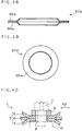
- Fig. 40 is a sectional view of the conventional technique. The conventional technique will be hereinafter explained with reference to both Figs. 2 and 40 .
- An exhaust manifold 2 is attached to a side of the engine 1 in order to discharge a combustion exhaust gas.
- a heat shield 3 is attached to the exhaust manifold 2 so as to cover this exhaust manifold 2.
- the heat shield 3 is mounted in order to control heat and sound, which is generated from the exhaust manifold 2 as a pulsating combustion exhaust gas passes through the inside of the exhaust manifold 2, not to propagate to the periphery of the engine 1. Consequently, as shown in Fig. 40 , the heat shield 3 has a structure in which a damping member 6 having heat insulating properties is nipped by an inner 4 and an outer 5 consisting of a metal plate, respectively. As this damping member 6, an inorganic fibrous material or an inorganic porous material is used.
- FIG. 40 A structure for attaching such a heat shield 3 to the exhaust manifold 2 will be explained as follows with reference to Fig. 40 .
- an insertion hole 8 for inserting a bolt 7 is formed, and a disk-like washer 9 is arranged.
- the bolt 7 is inserted through the washer 9 and the heat shield 3 and screwed to an attachment boss 10 of the exhaust manifold 2. Consequently, the heat shield 3 is attached to the exhaust manifold 2.
- JP-A-10-266850 As an example of the heat shield 3 of the above -mentioned conventional technique, an heat shield disclosed in a published document JP-A-10-266850 is known.
- the heat shield of JP-A-10-266850 is constituted by placing two steel sheets one on top of the other.
- the heat shield with such a structure is heavy, and a momentum of a vibration of the heat shield due to a vibration, which is transmitted from an exhaust manifold via a bolt or the like, increases. Consequently, a problem occurs in that a crack tends to be caused in a portion where the heat shield is attached to the bolt or the like, and durability is deteriorated.
- the conventional technique has problems as described below.
- the heat shield 3 is attached to the exhaust manifold 2 as shown in Fig. 40 , concerning a vibration that is generated from the exhaust manifold 2 and transmitted through the bolt 7, it is difficult to absorb a vibration component in a direction crossing an axis of the bolt 7 indicated by arrow A3 in Fig. 40 . Due to propagation of such a vibration component, the heat shield 3 produces resonance, or metal fatigue is caused around the portion where the bolt 7 of the heat shield 3 is attached. Consequently, problems such as an increase of noise and formation of a crack in the heat shield 3 occur, and a problem arises in a quality of the heat shield 3.
- Fig. 41 is a sectional view showing a vibration damping mount 11 that is used for attaching the heat shield 3 to the exhaust manifold or the like. A structure of the vibration damping mount 11 will be hereinafter explained.
- a collar 12 is mounted in an insertion hole 8 of the heat shield 3.
- the collar 12 includes a cylindrical coupling section 13 and a pair of flange sections 14 and 15 that are formed integrally at both ends of the coupling section 13, respectively, and expand outwardly in a radial direction thereof.
- a distance between the flange sections 14 and 15 is formed larger than a thickness of the heat shield 3.
- Damping sheets 16 and 17, which are made of, for example, a felt-like body consisting of stainless steel fiber or an expand metal of stainless steel, are inserted between each of the flange sections 14 and 15 and the heat shield 3.
- the flange sections 14 and 15 of the collar 12 nip and hold the pair of damping sheets 16 and 17 that nip the heat shield 3.
- the bolt 7 is inserted through the collar 12 and screwed into an attachment boss of exhaust manifold 2. Consequently, the heat shield 3 is attached to the exhaust manifold 2 via the vibration damping mount 11.
- a vibration damping mount disclosed in, for example, a published document JP -A-2002-235800 is known.
- Fig. 42 is a sectional view of a vibration damping mount 11b that is disclosed JP-A-2002-235800 .
- the vibration damping mount 11b of the conventional technique will be hereinafter explained with reference to Fig. 42 .
- Components in Fig. 42 corresponding to the components, which have already been explained, will be denoted by the identical reference numerals and signs and will not be explained anew.
- the vibration damping mount 11b includes: a substantially annular damping member 18 formed of stainless steel or the like that is provided externally surrounding the bolt 7; and a grommet 20 formed of aluminum alloy and having substantially an S shaped section that serves as a coupling component.
- the grommet 20 has an insertion hole 19 through which the bolt 7, which is screwed into the attachment boss 10 or the like of the exhaust manifold 2, is inserted.
- the grommet 20 includes: a first retaining section 20a having a shape with an inner peripheral edge of a circular metal plate folded back to an outer peripheral portion in order to retain the heat shield 3; a second retaining section 20b having a shape with an outer peripheral edge of the circular metal plate folded back to an inner peripheral portion in order to retain the damping member 18; and a coupl ing section 20c that is formed bending over the first retaining section 20a and the second retaining section 20b and couples the heat shield 3 and the damping member 18 via the first retaining section 20a and the second retaining section 20b.
- the collar 12 formed of a galvanized steel plate is provided between an inner periphery of the damping member 18 and the bolt 7. Gaps are provided in an axial direction and a radial direction of the bolt 7 between the collar 12 and the damping member 18.
- a vibration which is generated from the exhaust manifold 2 and travels through the bolt 7, is transmitted to the heat shield 3 via the damping member 18 and the grommet 20. This vibration is attenuated by actions of the damping member 18 and the grommet 20.
- the present invention has been devised in order to solve the problems inherent in the heat shield and the vibration damping mount of the conventional techniques. It is an object of the present invention to provide a vibration damping mount with which the breakage due to wearing and the occurrence of electrolysis are prevented and the vibration damping action is improved remarkably and to provide a metal heat shield with which the sound insulation performance is improved remarkably.
- a vibration from the one object member is transmitted through the screw member, the collar member, the damping member, and the coupling member.
- the second retaining section, the coupling section, and the first retaining section of the coupling member are provided in this order from the side of the one member that is a vibration source.
- the first retaining section is located on the opposite side of the one object member with respect to the damping member.
- the film containing at least a metal or a metal compound having an ionization tendency closer to that of aluminum than that of iron is formed on the surface of the damping member formed of an iron alloy that includes the coupling section, which is coupled to the other object member, and the vibration section, which is an area separated from the other object member and the screw member and is allowed to be bent and displaced. Therefore, actions and effects same as those described above can be realized.
- the first direction of the plural corrugate shapes formed on the metal heat shield is set in the direction crossing the major ridge equivalent portion.
- the corrugate shapes realize a function of a rib with respect to a vibration around the ridge equivalent portion.
- the metal heat shield when the metal heat shield is mounted against a vibration source, the metal heat shield is also vibrated by transmission of a vibration from the vibration source.
- the metal heat shield is vibrated by this vibration, it is known that portions of the metal heat shield on both sides of the major ridge equivalent portion tend to vibrate to flop around the portion.
- vibration of the metal heat shield can be controlled by the rib action. Therefore, occurrence of a crack in the metal heat shield can be prevented, and a quality of the metal heat shield can be improved remarkably.
- the flange section is formed at least in a part of the outer peripheral portion of the metal heat shield having a three-dimensional shape.
- this flange section realizes a function of a rib with respect to vibration at the time of vibration of the metal heat shield. Consequently, a vibration characteristic of the metal heat shield is also improved.
- the corrugate shapes of the crush object portion including the flange section of the metal heat shield are crushed to be formed in a substantially tabular shape.
- a first direction, in which corrugate shape s formed on a metal heat shield extend, is set in a direction crossing a major ridge equivalent portion of the metal heat shield.
- the corrugate shapes realize a function of a rib with respect to a vibration around the ridge equivalent portion. According to this rib action, a vibration of the metal heat shield can be controlled, occurrence of a crack in the metal heat shield can be prevented, and a quality of the metal heat shield can be improved remarkably.
- Figs. 1 to 9 show a first embodiment of the present invention.
- Fig. 1 is a sectional view schematically showing a state in which a vibration damping mount 21 of this embodiment is used.
- Fig. 2 is a front view of an engine 1 showing a structure forming a basis of the present invention.
- Fig. 3 is a sectional view of the engine 1 viewed from a section line X3-X3 in Fig. 2 .
- Fig. 4 is an enlarged front view of a metal exhaust manifold heat shield (hereinafter referred to as heat shield) 1 of an embodiment of the present invention.
- Fig. 5 is a sectional view of the heat shield viewed from a section line X5-X5 in Fig. 4 .
- Fig. 1 is a sectional view schematically showing a state in which a vibration damping mount 21 of this embodiment is used.
- Fig. 2 is a front view of an engine 1 showing a structure forming a basis of the present invention.
- Fig. 3 is a sectional view of the engine 1 viewed
- FIG. 6 is a sectional view of the heat shield viewed from a section line X6-X6 in Fig. 4 .
- Fig. 7 is a sectional view of the heat shield viewed from a section line X7-X7 in Fig. 4 .
- Fig. 8 is a simplified sectional view of the engine 1 viewed from a section line X8-X8 in Fig. 2 .
- Fig. 9 is a view illustrating characteristics of this embodiment.
- a heat shield 3 which is an embodiment of the metal exhaust manifold heat shield of the present invention, is attached to an exhaust manifold 2 mounted on the engine 1.
- plural object members include the engine 1, the exhaust manifold 2, and the heat shield 3.
- the exhaust manifold 2 constitutes one object member
- the heat shield 3 constitutes the other object member
- the bolt 7 constitutes a screw member.
- the heat shield 3 has a structure in which a damping member 6 having heat insulating properties is nipped between an inner 4 and an outer 5 consisting of a metal plate, respectively.
- the heat shield 3 in this embodiment will be hereinafter explained.
- the heat shield 3 of this embodiment is constituted by stacking a pair of metal plates (e.g., NIMBUS manufactured by T&N) 4 and 5 consisting of an aluminum alloy having a specific gravity of about 2.7 and a heat resistant vibration damping member (hereinafter referred to as damping member) 6, which is nipped by the metal plates 4 and 5, consisting of inorganic fiber or the like, and is formed in a three-dimensional shape along an external shape of the exhaust manifold 2.
- the heat shield 3 includes a sidewall T1 and a top T2 that couples an entire periphery of an end of this sidewall T1.
- the sidewall T1 and the top T2 continue at an obtuse angle ⁇ .
- the metal plates 4 and 5 are explained as including an aluminum foil or an aluminum alloy foil or a thin plate consisting of aluminum or an alloy of aluminum.
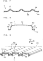
- the metal plates 4 and 5 used in the heat shield 3 of this embodiment have a shape in which corrugate shapes 59 having alternately repeated elevated portions 57 and valley portions 58 extend in a first direction A1, and other corrugated shapes continue in a second direction A2 that is a direction crossing the first direction A1, preferably a direction perpendicular to the first direction A1.
- first rising portions 60 and second rising portions 61 rise from the valley portions 58 and are arranged alternately in a longitudinal direction thereof.
- flat portions 62 and recessed portions 63 are arranged alternately.
- the first rising portions 60 include a pair of sidewalls 64 and 65, which rise in a substantially trapezoid shape from the valley portions 58, and relatively flat tops 68, which are formed by coupling tips of the sidewalls 64 and 65 each other.
- the first rising portions 60 are bent inward such that tips of the first rising portions 60 are wider than base ends thereof.
- the second rising portions 61 are formed by crushing the first rising portions 60 in substantially a width direction by a predetermined degree.
- the second rising portions 61 includes a pair of sidewalls 69 and 70, which rise from the flat portions 62, and recessed portions 73, which couple tips of the sidewalls 69 and 70 each other and are recessed to a lower side in Fig. 6 .
- Such second rising portions 61 and recessed portions 63 are formed so as to continue in a disconnected manner, respectively, in the second direction A2 that is a direction substantially perpendicular to the first direction A1 in which the plural corrugate shapes 59 extend.
- projected portions of the elevated portions 57 of the metal plate 5 are fit into inwardly bent inner peripheral portions of the elevated portions 57 of the metal plate 4.
- the sidewalls 69 and 70 are also wider in tips than in the base ends thereof and formed in an inwardly bent shape.
- projected portions of the second rising portions 61 of the metal plate 5 are fit into inwardly bent inner peripheral portions of the second rising portions 61 of the metal plate 4. Consequently, the metal plates 4 and 5 can be fixed to each other firmly without using any specific hold-down or fastener.
- the metal plates 4 and 5 are fixed each other in the same manner even in the case in which the damping member 6 consisting of inorganic fiber or the like is interposed between them. This is because the mutual coupling of the metal plates 4 and 5 depends upon a mechanical engagement relation thereof.
- the heat shield 3 is formed by stamping the metal plates 4 and 5, which have such a shape and nip the damping member 6, in a three-dimensional shape along an external shape of the exhaust manifold 2.
- a flange 78 with the corrugate shapes crushed by stamping is formed in an outer peripheral portion of the sidewall T1 of the heat shield 3 formed in the three dimensional shape. As shown in Fig. 8 , this flange 78 is folded back to an inside of the heat shield 3, whereby a folded-back portion 79 is formed.
- this folded-back portion 79 prevents an assembly worker, who works holding the heat shield 3, or a worker or a general user, who is likely to hold the heat shield 3 in the case of maintenance of a vehicle after manufacturing, from hurting fingers in a process of mounting the heat shield 3 on the exhaust manifold 2 of the vehicle engine 2 in a manufacturing process of the vehicle.
- crush object portions for which folding-down, drilling, or inscription is required to be preformed in the metal plates 4 and 5 having corrugate shapes, such as the flange 78, portions to be drilled, and portions to be inscribed of the heat shield 3 are formed in a substantially tabular shape with the corrugate shapes in the crush object portions crushed by stamping.
- the corrugate shapes of the crush object portions including the flange 78 is formed in a substantially tabular shape, in the case in which bending, drilling, inscription, or the like of the outer peripheral portion of the heat shield 3 is performed, the object portions of such working can be treated in the same manner as the tabular metal plate.
- the heat shield 3 of this embodiment is formed in a three-dimensional shape along a three-dimensional external shape of the exhaust manifold 2.
- one or more ridge equivalent portions 80 which are bent portions of the metal plates 4 and 5, are formed in the heat shield 3.
- stamping to a three-dimensional shape is applied to the metal plates 4 and 5 such that the first direction A1, which is the longitudinal direction of the corrugate shapes 59, is a direction crossing the major ridge equivalent portion 80 of these plural ridge equivalent portions 80.
- the major ridge equivalent portion 80 is a portion where bent portions having a relatively large curvature, which characterizes an overall shape of the heat shield 3, continue.
- the major ridge equivalent portion 80 indicates a bent portion extending over a relatively long dimension, which substantially determines an external shape of the heat shield 3, of bent portions of various sizes formed on the heat shield 3.
- the heat shield 3 When the heat shield 3 is mounted on the exhaust manifold 2, the heat shield 3 is also vibrated by transmission of a vibration from the exhaust manifold 2. When the heat shield 3 is vibrated by this vibration, it is assumed that portions of the heat shield 3 on both sides of the major ridge equivalent portion 80 are vibrated largely like wings of a butterfly around the major ridge equivalent portion 80. When such a vibration occurs, metal fatigue is caused in portions near the ridge equivalent portions 80 of the heat shield 3 due to repeated bending, and a crack easily occurs in the portions.
- the first direction A1 of the plural corrugate shapes 59 formed on the heat shield 3 is set in a direction crossing the major ridge equivalent portion 80, preferably a direction perpendicular to the major ridge equivalent portion 80.
- the corrugate shape 59 realizes a function of a rib with respect to a vibration around the ridge equivalent portion 80. Consequently, a vibration of the heat shield 3 can be controlled, occurrence of a crack in the heat shield 3 can be prevented, and a quality of the heat shield 3 can be improved remarkably.
- the second rising portio ns 61 shown in Figs. 4 to 6 which extend in a disconnected manner in the second direction A2 and continue in the first direction A1, also realize a function of a rib and control the vibration.
- the vibration damping mount 21 which is used in this embodiment, will be hereinafter explained with reference to Fig. 1 .
- the vibration damping mount 21 of this embodiment includes: a substantially annular damping member 40, which is provided externally surrounding the bolt 7, constituted by a tabular material such as an expand metal of stainless steel, and has a zinc film formed on a surface thereof by, for example, Dacrotized (trademark) treatment; and a grommet 41 that is a coupling member formed of an aluminum alloy and has substantially an S shaped section.
- the grommet 41 has an insertion hole 42 through which the bolt 7, which is screwed into the boss for bolt 10 of the exhaust manifold 2, is inserted.
- the grommet 41 includes: a first retaining section 43 having a shape with an inner peripheral edge of a circular metal plate folded back to an outer peripheral portion in order to retain the heat shield 3; a second retaining section 44 having a shape with an outer peripheral edge of the circular metal plate folded back to an inner peripheral portion in order to retain the damping member 40; and a coupling section 45 that is formed bending over the first retaining section 43 and the second retaining section 44 and elastically couples the heat shield 3 and the damping member 40 via the first retaining section 43 and the second retaining section 44 so as to be displaced freely in an axial direction and a radial direction of the bolt 7.
- the coupling section 45 is a portion extending from a bent portion of the first retaining section 43 to a bent portion of the second retaining section 44.
- the second retaining section 44, the coupling section 45, and the first retaining section 43 are provided in this order from the exhaust manifold 2 side.
- a collar member 22 formed of a galvanized steel plate is provided between an inner periphery of the damping member 40 and the bolt 7.
- the collar member 22 includes a cylinder section 27 and flange sections 28 and 31 that are formed integrally at both ends in an axial direction of the cylinder section 27, respectively.
- the collar member 22 and the damping member 40 are formed and arranged such that gaps 37 in an axial direction and a radial direction of the bolt 7 are formed between the collar member 22 and the damping member 40.
- vibration damping mount 21 a vibration, which is generated from the exhaust manifold 2 and travels through the bolt 7, is transmitted to the heat shield 3 via the collar member 22, the damping member 40, and the grommet 41.
- the gaps 37 in the axial direction and the radial direction of the bolt 7 are formed between the collar member 22 and the damping member 40.
- the vibration transmitted from the bolt 7 to the collar member 22 is significantly controlled by the gaps 37 in a degree of transmission to the collar member 22. Consequently, a buffer action of the vibration damping mount 21 with respect to a vibration is improved remarkably, and a vibration control function of the heat shield 3 can be improved remarkably.
- the damping member 40 can perform a bending motion in the axial direction of the bolt 7 easily because it is constituted by a tabular material such as an expand metal. Therefore, the vibration transmitted to the damping member 40 from the collar member 22 is converted into the bending motion of the damping member 40 and absorbed.
- the buffer action of the vibration damping mount 21 is also improved, and the damping function of the heat shield 3 is also improved.
- the second retaining section 44, the coupling section 45, and the first retaining section 43 of the grommet 41 are provided in this order from the exhaust manifold 2 side.
- the first retaining section 43 is located on the opposite side of the exhaust manifold 2 with respect to the damping member 40.
- a zinc film having an ionization tendency closer to that of aluminum than that of iron is formed on the surface of the damping member 40.
- the collar member 22 is formed of a galvanized steel plate, and the grommet 41 is formed of an aluminum alloy. Therefore, in this embodiment, an action of reducing a difference of the ionization tendency between the damping member 40 and the grommet 41 is realized. Consequently, occurrence of electrolysis in the grommet 41 and the damping member 40 is controlled. In this regard, a quality of the vibration damping mount 21 is also improved remarkably.
- the first retaining section 43 of the grommet 41 may be fixed in abutment with the inner peripheral end of the heat shield 3 rather than being folded back as described above.
- this embodiment can realize actions and effects same as those in the above-mentioned embodiment.
- Fig. 10 is a sectional view schematically showing a vibration damping mount 21a according to a second embodiment which is not an embodiment of the present invention but an example useful for its understanding .
- Fig. 11 is a sectional view showing a principle of this embodiment.
- Fig. 12 is an enlarged sectional view showing the principle of this embodiment.
- Fig. 13 is a graph showing an effect of this embodiment.
- the vibration damping mount 21a according to the second embodiment will be explained with reference to Figs. 10 to 13 .
- the vibration damping mount 21a includes: a collar member 22; spring washers 23 and 24, which are damping members with thickness t1, mounted on the collar member 22; and circular grommets 25 and 26 mounted on outer peripheral edges of the spring washers 23 and 24, respectively.
- the collar member 22 includes: a collar piece 29 that includes a cylinder section 27 and a flange section 28 integrally formed at one end in an axial direction of the cylinder section 27; and a collar piece 32 that includes a cylinder section 30 having a diameter larger than the cylinder section 27 and a flange section 31 integrally formed at one end in an axial direction of the cylinder section 30.
- the flanges 28 and 31 are constituted to be apart from each other by a distance L1 shown in Fig. 10 in a state in which the cylinder section 27 is pressed and fixed in the cylinder section 30. Plate thicknesses of collar pieces 29 and 32, and the he like are selected such that the distance L1 satisfies the following condition.
- the gap 37 has a length L2, which is calculated as follows, in the axial direction of the bolt 7.
- L 2 L 1 ⁇ 2 xt 1
- the collar member 22 having the flange sections 28 and 31 and the cylinder section 33 is constituted by combining the collar pieces 29 and 32 as described above.
- the spring washers 23 and 24 are formed of any one of plate-like materials such as a metal plate, a punching metal, an expand metal, and a wire gauze. As an example, this embodiment will be explained assuming that the spring washers 23 and 24 are formed of an expand metal.
- the spring washers 23 and 24 are formed in substantially a circular shape. As shown in Fig. 12 , an insertion hole 34 having an inner diameter L5, which is larger than an outer diameter L3 of the cylinder section 33 of the collar member 22 and smaller than an outer diameter L4 of the flange sections 28 and 31, is formed in the spring washers 23 and 24.
- the collar member 22 is divided into two as shown in Fig. 10 , and after mounting the spring washers 23 and 24 on, for example, the collar piece 29, the collar piece 32 is pressed into the collar piece 29. In this way, the spring washers 23 and 24 are mounted on the collar member 22. Consequently, the gap 37 has a length (L5-L3) in the radial direction of the bolt 7.
- grommets 25 and 26 are mounted on outer peripheries of the spring washers 23 and 24.
- the grommets 25 and 26 are formed by folding back an outer periphery of a circular metal plate consisting of, for example, a stainless steel plate or an aluminum alloy to the inside. Therefore, the grommets 25 and 26 are formed so as to wrap the outer peripheries of the spring washers 23 and 24.
- the spring washers 23 and 24 are formed of an expand metal, and sharp cut ends project on the outer periphery in a state in which the spring washers 23 and 24 remain cut.
- the heat shield 3 is nipped and retained between the spring washers 23 and 24 mounted with such grommets 25 and 26.
- the bolt 7 is inserted through the inside of the cylinder section 33 of the collar member 22 to be screwed into the attachment boss 10 or the like of the exhaust manifold 2. In this way, the heat shield 3 is attached to the exhaust manifold 2.
- a vibration which is generated from the exhaust manifold 2 and travels through the bolt 7, is transmitted to the spring washers 23 and 24 via the collar member 22.
- the gap 37 is provided between the pair of flange sections 28 and 31 of the collar member 22 and the spring washers 23 and 24. Consequently, the collar member 22 and the spri ng washers 23 and 24 are allowed to be relatively displaced in a direction parallel to and a direction crossing the axial direction of the bolt 7. Therefore, the vibration from the bolt 7 is absorbed by the relative displacement of the collar member 22 an d the spring washers 23 and 24, whereby the transmission of the vibration to the spring washers 23 and 24 can be controlled.
- the vibration from the spring washers 23 and 24 is transmitted to the heat shield 3.
- the spring washers 23 and 24 are formed in a plate shape, the spring washers 23 and 24 bend in the axial direction of the bolt 7. Consequently, the transmission of the vibration from the spring washers 23 and 24 to the heat shield 3 is controlled.
- a horizontal axis shows a frequency
- a vertical axis shows an acceleration of a vibration.
- a curve g1 indicates a result of measuring a vibration of only the collar member 22
- a curve g2 indicates a result of measuring a vibration transmitted to the heat shield 3 of the vibration damping mount 11 having the structure shown in Fig. 29
- a curve g3 indicates a result of measuring a vibration of a trial product without the gap 37 between the collar member 22 and the spring washers 23 and 24
- a curve g4 indicates a result of measuring a vibration in this embodiment.
- a damping characteristic in all frequency bands of vibrations generated from the engine 1 and the exhaust manifold 2 is improved in the case in which the spring washers 23 and 24 constituted by, for example, an expand metal of this embodiment are used compared the case in which the felt-like damping sheet shown in Fig. 29 is used.
- the damping characteristic is improved in the example of the structure provided with the gap 37. Above all, the damping characteristic in a relatively low frequency band is improved.
- the exhaust manifold 2 also serves as a heat source for causing a combustion exhaust gas from the engine 1 to flow.
- heat from the exhaust manifold 2, which is transmitted through the bolt 7, is transmitted to the spring washers 23 and 24 via the collar member 22, thermal conduction is blocked efficiently by the gap 37 between the pair of flange sections 28 and 31 of the collar member 22 and the spring washers 23 and 24. Consequently, transmission of the heat from the exhaust manifold 2 to the heat shield 3 is also controlled efficiently.
- Fig. 14 is a sectional view of a vibration damping mount 21b of a third embodiment which is not an embodiment of the present invention but an example useful for its understanding .
- Fig. 15 is a sectional view of a comparative example of this embodiment.
- Fig. 16 is a sectional view showing characteristics of the vibration damping mount 21b.
- Fig. 17 is a plan view of spring washers 23 and 24 of the vibration damping mount 21b.
- Fig. 18 is a perspective view of the spring washers 23 and 24.
- Fig. 19 is a perspective view of a comparative example for the vibration damping mount 21b.
- Fig. 20 is a sectional view of the comparative example.
- Fig. 21 is a sectional view showing an operational example of the vibration damping mount 21b.
- Fig. 22 is a sectional view showing another operational example of the vibration damping mount 21b.
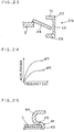
- Fig. 23 is a sectional view showing yet another operational example of the vibration damping mount 21b.
- the vibration damping mount 21b of this embodiment will be hereinafter explained with reference to Figs. 14 to 24 .
- This embodiment is similar to the second embodiment. Components corresponding to those in the second embodiment are denoted by the identical reference numerals and signs. In addition, in Figs. 15 to 23 , only one spring washer 24 and one grommet 26 are shown for simplification of the explanation. This embodiment is characterized in that, in the vibration damping mount 21a of the second embodiment, the grommets 25 and 26 are not used, and the outer peripheries of the spring washers 23 and 24 are formed as free ends that vibrate freely.
- a length c in a radial direction of a part contributing to the bending displacement of the spring washers 23 and 24 is calculated as follows with respect to a projection length a, by which inward ends in the radial direction of the grommets 25 and 26 proje ct from inward ends in the radial direction of the heat shield 3, and a distance b from the outer peripheries of the flange sections 28 and 31 to the inward ends in the radial direction of the heat shield 3.
- c b ⁇ a
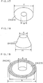
- the spring washers 23 and 24 are generally plate-like members consisting of, for example, an expand metal, and as shown in Figs. 17 and 18 , the following relation is established among an inner diameter e and an outer diameter f of the spring washers 23 and 24 in a natural state and an inner diameter e and an outer diameter fl of the spring washers 23 and 24 in a bent state.
- f 1 ⁇ f On the other hand, as shown in Figs.
- the outer diameters h and h1 are substantially equal.
- the spring washers 23 and 24 used in the vibration damping mount 21b of this embodiment are bent and displaced freely in an axial direction of the collar member 22, and a degree of bending of the spring washers 23 and 24 is increased remarkably.
- a horizontal axis shows a frequency
- a vertical axis shows an acceleration of a vibration.
- a curve g5 indicates a result of measuring a vibration of the vibration damping mount 21a of the second embodiment having the grommets 25 and 26 mounted on the spring washers 23 and 24, and a curve g6 indicates a result of measuring a vibration in this embodiment.
- the vibration damping mount 21a of the second embodiment attains remarkable actions and effects compared with the conventional technique as described above, the vibration damping mount 21b of this embodiment attains a damping characteristic more remarkable than that in the second embodiment.
- the transmission of a vibration from the exhaust man ifold 2 to the heat shield 3 is controlled efficiently.
- a situation in which the heat shield 3 is resonated by the transmitted vibration or metal fatigue occurs near the attachment portion of the bolt 7 to the heat shield 3 can be prevented, a situation of an increase in noise, occurrence of a crack in the heat shield 3, and the like can be eliminated, and a quality of the heat shield 3 can be improved remarkably.
- the spring washers 23 and 24 formed in a plate shape since the spring washers 23 and 24 formed in a plate shape are used, the spring washers 23 and 24 deform at the time when a vibration is transmitted. The vibration is absorbed by this deformation. Therefore, compared with the case in which the spring washers 23 and 24 consist of a felt-like material made of inorganic fiber or the like, a situation in which a damping member deteriorates due to secular changes and self weights thereof, compression and restoration characteristics fall, and a vibration control action falls can be prevented. In addition, in the case of the felt-like material, a problem is assumed in that the fiber decomposes and flies as time elapses. However, in this embodiment, such a situation is also prevented.
- Fig. 26 is a sectional view of a vibration damping mount 21c of a fourth embodiment which is not an embodiment of the present invention but an example useful for its understanding . This embodiment will be hereinafter explained with reference to Fig. 26 .
- This embodiment is similar to the above-mentioned embodiments. Components corresponding to those in the above-mentioned embodiments are denoted by the identical reference numerals and signs.
- This embodiment is characterized in that at least one of the spring washers 23 and 24 used in the above-mentioned embodiments is used, and at least one of the spring washers 23 and 24 to be used is fixed to the heat shield 3 with spot welding or an arbitrary fixing technique. In the following explanation, as an example, a case of using only the spring washer 24 is assumed.
- an attachment structure for attaching the heat shield 3 to the exhaust manifold 2 a structure described below is used.
- the heat shield 3 an insertion hole 8 with a diameter j for inserting the bolt 7 is provided, the spring washer 24 is arranged so as to cover the insertion hole 8, and the spring washer 24 is fixed to the heat shield 3 in a coupling portion 46 around the insertion hole 8 by a technique such as spot welding or a rivet.
- the bolt 7 is inserted through the insertion hole 34 formed in this spring washer 24 and screwed into an attachment boss 49 or the like of the exhaust manifold 2 to attach the heat shield 3 to the exhaust manifold 2.
- the free vibration portion 48 is an area where free vibration occurs due to bending displacement between a fixed portion 47, which is fixed between the attachment boss 49 with the diameter m of the exhaust manifold 2 and the bolt 7 with the diameter k of the spring washer 24, and the coupling portion 46.
- the damping member 40 may be formed of a damping alloy body including at least Al with a content of 6 to 10 weight % and the balance Fe or formed of an alloy material including this damping alloy body.
- a damping alloy body for example, an Fe-Al damping alloy manufactured by Kabushiki Kaisha Urban Materials can be used.
- the damping alloy has an Al content of 6 to 10 weight % and, other than Al, includes Fe and inevitable impurities (Si of 0.1 weight % or less; Mn of 0.1 weight % or less; C, N, S and O of 0.1 weight % or less in total).
- Si of 0.1 weight % or less
- Mn of 0.1 weight % or less
- C, N, S and O of 0.1 weight % or less in total.
- an average particle diameter of a crystal of the damping alloy body is in a range of 300 to 700 ⁇ m.
- a thickness of this damping alloy body is, for example, about 0.1 to 1.0 mm.
- a vibration damping mechanism therefor is according to magnetic/mechanical history loss following irreversible movement of a magnetic wall.
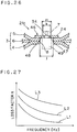
- the inventor measured a damping coefficient, which indicates a damping capacity of vibration, for a steel plate, the damping alloy body, and a normal sandwich type damping steel plate, respectively. Results of the measurement are indicated by lines L1, L2 and L3 in Fig. 27 . In this way, the inventor confirmed that a damping characteristic was improved remarkably in the damping alloy body compared with the normal metal plate.
- a vibration damping mount 21d according to a fifth embodiment which is not an embodiment of the present invention but an example useful for its understanding will be hereinafter explained.
- Fig. 28 is a sectional view of the vibration damping mount 21d of this embodiment.
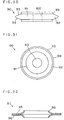
- Fig. 29 is a plan view of the vibration damping mount 21d in Fig. 28 .
- Fig. 30 is a front view of a spacer 90 used in this embodiment.
- Fig. 31 is a plan view of the spacer 90.
- Fig. 32 is a sectional view of a nip member 97 used in this embodiment.
- Fig. 33 is a plan view of the nip member 97.
- This embodiment is similar to the above-mentioned embodiments. Components corresponding to those in the above-mentioned embodiments are denoted by the identical reference numerals and signs.
- the vibration damping mount 21d of this embodiment has an insertion hole 100, through which the bolt 7 is inserted, and includes the spacer 90 formed of, for example, a metal material having a relatively low friction coefficient and a high hardness.
- the spacer 90 includes a substantially cylindrical base section 91, in which the insertion hole 100 is formed, and a sliding section 92, which integrally continues outwardly in a radial direction of the base section 91 and has a pair of sliding surfaces 93 and 94, a distance between which in an axial direction decreases toward a further outside in the radial direction.
- the sliding surfaces 93 and 94 have a shape of a side of a truncated cone and are constituted as relatively flat taper surfaces in the radial direction.
- a stepped portion 99 elevated in the axial direction of the bolt 7 is formed near a boundary of the sliding section 92 and the base section 91.
- the substantially annular nip member 97 which is constituted by a tabular metal material having a spring property such as an expand metal of stainless steel and has a zinc film formed on a surface thereof by, for example, Dacrotized (trademark) treatment, is arranged in the outside in the radial direction of the spacer 90.
- the nip member 97 includes a pair of nip pieces 95 and 96 that are arranged increasingly spaced apart from each other in the axial direction from an outside in the radial direction toward an inside in the radial direction.
- the nip pieces 95 and 96 are constituted so as to elastically nip the sliding section 92 of the spacer 90 from sides opposed to each other in the axial direction on the inside in the radial direction.
- an elevated portion 98 which is engageable with a stepped portion 99 at the time of displacement to the inside in the radial direction of the nip member 97, is formed with an interval L10 in the radial direction from the stepped portion 99 of the spacer 90, respectively.
- the spacer 90 and the nip member 97 have such a structure, whereby mutual displacement at least in the radial direction is allowed.
- a grommet 41 which is a coupling member formed of, for example, an aluminum alloy and having substantially an S shaped section, is provided.
- the grommet 41 has an insertion hole 42 through which the bolt 7 to be screwed into the boss for bolt 10 of the exhaust manifold 2 is inserted.
- grommet 41 includes: a first retaining section 43 having a shape with an inner peripheral edge of a circular metal plate folded back to an outer peripheral portion in order to retain the heat shield 3; a second retaining section 44 having a shape with an outer peripheral edge of the circular metal plate folded back to an inner peripheral portion in order to retain the nip member 97; and a coupling section 45 that is formed bending over the first retaining section 43 and the second retaining section 44.
- the coupling section 45 is a portion extending form a bent portion of the first retaining section 43 to a bent portion of the second retaining section 44.
- the second retaining section 44, the coupling section 45, and the first retaining section 43 are provided in this order from the exhaust manifold 2 side.
- a through -hole is formed in a portion of the heat shield 3 where the vibration damping mount 21d is mounted. A part around this through -hole is the above-mentioned substantially planar crush object portion where a crush portion 3a is formed in advance. Therefore, the first retaining section 43 of the grommet 41 retains this crush portion 3a.
- vibration damping mount 21d a vibration, which is generated from the exhaust manifold 2 and travels through the bolt 7, is transmitted to the heat shield 3 via the spacer 90, the nip member 97, and the grommet 41.
- the sliding section 92 on the outside in the radial direction of the spacer 90 is elastically nipped by the pair of nip pieces 95 and 96 of the nip member 97.
- the spacer 90 and the nip member 97 are allowed to be displaced from each other in the radial direction as described above. Therefore, when the spacer 90 vibrates in the radial direction, the nip member 97 and the spacer 90 are displaced from each other in the radial direction while the pair of nip pieces 95 and 96 slide each other along the sliding section 92 of the spacer 90. Consequently, the vibration in the radial direction of the spacer 90 is absorbed by the mutual displacement in the radial direction of the spacer 90 and the nip member 97.
- the nip member 97 is constituted by the pair of nip pieces 95 and 96 having a spring property. Moreover, the pair of nip pieces 95 and 96 elastically nip the sliding section 92 of the spacer 90 and are not fixed to the sliding section 92. Therefore, the spacer 90 can be vibrated and displaced in the axial direction while sliding with respect to the nip member 97 by a vibration in the axial direction of the spacer 90. Moreover, since the spacer 90 is formed of a metal material having a spring property, the nip member 97 is bent and vibrated in the axial direction by the vibration in the axial direction of the spacer 90.
- the second retaining section 44, the coupling section 45, and the first retaining section 43 of the grommet 41 are provided in this order from the exhaust manifold 2 side.
- the first retaining section 43 is located on the opposite side of the exhaust manifold 2 with respect to the nip member 97.
- a zinc film hav ing an ionization tendency closer to that of aluminum than that of iron is formed on the surface of the nip member 97. Therefore, even in the case in which the nip member 97 is formed of a stainless steel plate and the grommet 41 is formed of an aluminum alloy as described above, an action of reducing a difference of the ionization tendency between the nip member 97 and the grommet 41 is realized. Consequently, occurrence of electrolysis in the grommet 41 and the nip member 97 is controlled. In this regard, a quality of the vibration damping mount 21d is also improved remarkably.
- the stepped portion 99 is formed in the spacer 90, and the elevated portion 98 is formed in the pair of nip pieces 95 and 96, respectively. Therefore, in the case in which displacement in the radial direction of the spacer 90 and the nip member 97 increases, the stepped portion 99 of the spacer 90 and the elevated portion 98 of the nip member 97 come into abutment and engage with each other to prevent excessive mutual displacement of the spacer 90 and the nip member 97. Consequently, occurrence of deficiency such as severe collision of the spacer 90 and the nip member 97 resulting in breakage of both of them can be prevented.
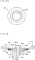
- FIG. 34 is a sectional view of the vibration damping mount 21e of this embodiment.
- Fig. 35 is a plan view of the vibration damping mount 21e in Fig. 34 .
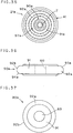
- Fig. 36 is a sectional view of a spacer 90a used in this embodiment.
- Fig. 37 is a plan view of the spacer 90a.
- Fig. 38 is a sectional view of a nip member 97a used in this embodiment.
- Fig. 39 is a plan view of the nip member 97a.
- This embodiment is similar to the fifth embodiment. Components corresponding to those in the fifth embodiment are denoted by the identical reference numerals and signs.
- a characteristic structure of this embodiment is that the spacer 90a and the nip member 97a of shapes and structures explained below are used instead of the spacer 90 and the nip member 97 used in the fifth embodiment.
- the spacer 90a of this embodiment includes a substantially cylindrical base section 91a, in which the insertion hole 100 is formed, and a sliding section 92a, which integrally continues outwardly in a radial direction of the base section 91a and has a sliding surface 92b forming an arc surface with a sectional shape projected toward an outside in a radial direction. More specifically, as shown in Fig. 36 , as a shape of an outer peripheral surface, the sliding surface 92b includes arc surfaces 93a and 94a having a 1/4 arc surface, respectively.
- the substantially annular nip member 97a which is constituted by a tabular metal material having a spring property such as an expand metal of stainless steel and has a zinc film formed on a surface thereof by, for example, Dacrotized (trademark) treatment, is arranged in the outside in the radial direction of the spacer 90a.
- the nip member 97a includes a pair of nip pieces 95a and 96a that are arranged increasingly spaced apart from each other in the axial direction from an outside in the radial direction toward an inside in the radial direction.
- the nip pieces 95a and 96a are constituted so as to elastically nip the sliding section 92a of the spacer 90s from sides opposed to each other in the axial direction on the inside in the radial direction.
- a specific elevated shape such as the elevated portion 98 of the nip member 97 in the fifth embodiment is not formed.
- the vibration damping mount 21e of this embodiment can realize actions and effects equivalent to those in the above-mentioned embodiments and can also realize spec ific actions and effects described below peculiar to this embodiment.
- the sliding surface 92b of the spacer 90a is formed as an arc surface projected outwardly in the radial direction. Therefore, when the spacer 90a and the nip member 97a are displaced from each other while sliding, the pair of nip pieces 95a and 96a of the nip member 97a are displaced smoothly along the sliding surface 92b forming the arc surface.
- the pair of nip pieces 95a and 96a are displaced smoothly along the sliding surface 92b forming the arc surface.
- the spacer 90a and the nip member 92a are displaced from each other in the radial direction.
- the nip member 92a can be displaced easily in the axial direction as well around the part near the contact position of the spacer 90a and the nip member 92a.
- the nip member 92a is displaced in the radial direction with respect to the spacer 90a and absorbs a radial direction component of a vibration from the spacer 90a.
- the nip member 92a is easily displaced in the axial direction with respect to the spacer 90a and absorbs an axial direction component of the vibration from the spacer 90a. Consequently, the vibration damping mount 21e can control the vibration from the spacer 90a remarkably.
- the vibration damping mount of the present invention can be applied to applications in a wide range of technical fields other than the engine for automobiles explained in the section of the embodiments of the present invention.
- the corrugate shapes realize a function of a rib with respect to a vibration around the ridge equivalent portion. According to this rib action, the vibration of the metal heat shield can be controlled, occurrence of a crack in the metal heat shield can be prevented, and a quality of the metal heat shield can be improved remarkably. Consequently, the present invention can be applied widely to many kinds of heat shields that are required to block heat, vibration, and noise, and also required to be light.
Landscapes
- Engineering & Computer Science (AREA)
- General Engineering & Computer Science (AREA)
- Mechanical Engineering (AREA)
- Chemical & Material Sciences (AREA)
- Combustion & Propulsion (AREA)
- Physics & Mathematics (AREA)
- Acoustics & Sound (AREA)
- Aviation & Aerospace Engineering (AREA)
- Vibration Prevention Devices (AREA)
- Exhaust Silencers (AREA)
- Bolts, Nuts, And Washers (AREA)
Description
- The present invention relates to a vibration damping mount that is used for mounting, for example, a heat shield or a housing on a member generating a vibration or heat, and relates to a metal heat shield that can be attached to, for example, an exhaust manifold of an internal combustion engine using such a vibration damping mount.
- A heat shield, which is an example of such a metal exhaust manifold heat shield or housing, is used i n an automobile. Such a heat shield, for example, a part near an exhaust manifold mounted on an engine of an automobile so as to control heat and sound from the exhaust manifold not to propagate to the periphery of the engine. Such a heat shield is attached to the exhaust manifold by a screw member such as a bolt.
-
Fig. 2 is a front view of anengine 1 of a vehicle such as an automobile showing a basic structure of this conventional technique.Fig. 40 is a sectional view of the conventional technique. The conventional technique will be hereinafter explained with reference to bothFigs. 2 and40 . Anexhaust manifold 2 is attached to a side of theengine 1 in order to discharge a combustion exhaust gas. Aheat shield 3 is attached to theexhaust manifold 2 so as to cover thisexhaust manifold 2. - The
heat shield 3 is mounted in order to control heat and sound, which is generated from theexhaust manifold 2 as a pulsating combustion exhaust gas passes through the inside of theexhaust manifold 2, not to propagate to the periphery of theengine 1. Consequently, as shown inFig. 40 , theheat shield 3 has a structure in which a dampingmember 6 having heat insulating properties is nipped by an inner 4 and an outer 5 consisting of a metal plate, respectively. As this dampingmember 6, an inorganic fibrous material or an inorganic porous material is used. - A structure for attaching such a
heat shield 3 to theexhaust manifold 2 will be explained as follows with reference toFig. 40 . In theheat shield 3, aninsertion hole 8 for inserting abolt 7 is formed, and a disk-like washer 9 is arranged. Thebolt 7 is inserted through thewasher 9 and theheat shield 3 and screwed to anattachment boss 10 of theexhaust manifold 2. Consequently, theheat shield 3 is attached to theexhaust manifold 2. - As an example of the
heat shield 3 of the above -mentioned conventional technique, an heat shield disclosed in a published documentJP-A-10-266850 JP-A-10-266850 - The heat shield with such a structure is heavy, and a momentum of a vibration of the heat shield due to a vibration, which is transmitted from an exhaust manifold via a bolt or the like, increases. Consequently, a problem occurs in that a crack tends to be caused in a portion where the heat shield is attached to the bolt or the like, and durability is deteriorated.
- In addition, in the case in which it is attempted to improve a sound insulation performance in such an heat shield, it is possible that a plate thickness is increased to control a degree of transmission of noise in the heat shield. However, in this case, a weight increases as described above. Therefore, there is a problem in that it is difficult to improve the sound insulation performance with such a conventional technique.
- Further, the conventional technique has problems as described below. In the case in which the
heat shield 3 is attached to theexhaust manifold 2 as shown inFig. 40 , concerning a vibration that is generated from theexhaust manifold 2 and transmitted through thebolt 7, it is difficult to absorb a vibration component in a direction crossing an axis of thebolt 7 indicated by arrow A3 inFig. 40 . Due to propagation of such a vibration component, theheat shield 3 produces resonance, or metal fatigue is caused around the portion where thebolt 7 of theheat shield 3 is attached. Consequently, problems such as an increase of noise and formation of a crack in theheat shield 3 occur, and a problem arises in a quality of theheat shield 3. - Moreover, concerning heat generated from the
exhaust manifold 2, other than radiant heat from theexhaust manifold 2 to theheat shield 3, heat is transmitted to theheat shield 3 via thebolt 7. - In the
heat shield 3 shown inFig. 40 , since thebolt 7 is in direct contact with thewasher 9, and thewasher 9 is in direct contact with theheat shield 3, the heat from theexhaust manifold 2 is easily transmitted to theheat shield 3. Consequently, temperature of theheat shield 3 rises, and the radiant heat increases to easily damage, for example, auxiliary devices, ducts, and harnesses around theengine 1 in a hood due to heat. Therefore, a problem arises in a quality as a heat shield. - As one of techniques for solving such problems, a technique shown in
Fig. 41 is possible.Fig. 41 is a sectional view showing avibration damping mount 11 that is used for attaching theheat shield 3 to the exhaust manifold or the like. A structure of thevibration damping mount 11 will be hereinafter explained. - A
collar 12 is mounted in aninsertion hole 8 of theheat shield 3. Thecollar 12 includes acylindrical coupling section 13 and a pair offlange sections coupling section 13, respectively, and expand outwardly in a radial direction thereof. A distance between theflange sections heat shield 3. Dampingsheets flange sections heat shield 3. - In other words, the
flange sections collar 12 nip and hold the pair of dampingsheets heat shield 3. Thebolt 7 is inserted through thecollar 12 and screwed into an attachment boss ofexhaust manifold 2. Consequently, theheat shield 3 is attached to theexhaust manifold 2 via thevibration damping mount 11. - In this technique, a vibration, which has traveled from the
bolt 7 to thecollar 12, is transmitted to the dampingsheets bolt 7 of the dampingsheets bolt 7 to theheat shield 3 is controlled. - On the other hand, in such a technique shown in
Fig. 41 , the dampingsheets sheets sheets Fig. 41 has a problem in that a quality with respect to a vibration damping action is low. - Moreover, as a yet another conventional technique for solving these problems, a vibration damping mount disclosed in, for example, a published document
JP -A-2002-235800 Fig. 42 is a sectional view of avibration damping mount 11b that is disclosedJP-A-2002-235800 vibration damping mount 11b of the conventional technique will be hereinafter explained with reference toFig. 42 . Components inFig. 42 corresponding to the components, which have already been explained, will be denoted by the identical reference numerals and signs and will not be explained anew. - The
vibration damping mount 11b includes: a substantially annular dampingmember 18 formed of stainless steel or the like that is provided externally surrounding thebolt 7; and agrommet 20 formed of aluminum alloy and having substantially an S shaped section that serves as a coupling component. Thegrommet 20 has aninsertion hole 19 through which thebolt 7, which is screwed into theattachment boss 10 or the like of theexhaust manifold 2, is inserted. - The
grommet 20 includes: afirst retaining section 20a having a shape with an inner peripheral edge of a circular metal plate folded back to an outer peripheral portion in order to retain theheat shield 3; asecond retaining section 20b having a shape with an outer peripheral edge of the circular metal plate folded back to an inner peripheral portion in order to retain the dampingmember 18; and acoupl ing section 20c that is formed bending over thefirst retaining section 20a and thesecond retaining section 20b and couples theheat shield 3 and the dampingmember 18 via thefirst retaining section 20a and thesecond retaining section 20b. In addition, thecollar 12 formed of a galvanized steel plate is provided between an inner periphery of the dampingmember 18 and thebolt 7. Gaps are provided in an axial direction and a radial direction of thebolt 7 between thecollar 12 and the dampingmember 18. - In the
vibration damping mount 11b having such a structure, a vibration, which is generated from theexhaust manifold 2 and travels through thebolt 7, is transmitted to theheat shield 3 via the dampingmember 18 and thegrommet 20. This vibration is attenuated by actions of the dampingmember 18 and thegrommet 20. - However, such conventional techniques have problems to be explained below. It is known that the
attachment boss 10, to which thebolt 7 is attached, is often formed in a size overlapping thegrommet 20 as indicated by an alternate long and two short dash lines inFig. 42 . In such a case, since thegrommet 20 and theattachment boss 10 are in contact with each other, noise due to this contact increases. In addition, it is assumed that contact portions of thegrommet 20 and theattachment boss 10 wear with time due to this contact to result in breakage. Consequently, a problem arises in a quality of thevibration damping mount 11b. - In addition, on the basis of a difference of the materials of the
collar 12, thedamping member 18, and thegrommet 20, a electrical current due to a difference of ionization tendencies of aluminum and stainless steel is generated between aluminum on a surface of thegrommet 20 and stainless steel of thedamping member 18, and electrolysis may occur in thegrommet 20 and thedamping member 18. Consequently, it is likely that thegrommet 20 and the dampingmember 18 are broken. As a result, again, a problem arises in the quality of thevibration damping mount 11b. - The present invention has been devised in order to solve the problems inherent in the heat shield and the vibration damping mount of the conventional techniques. It is an object of the present invention to provide a vibration damping mount with which the breakage due to wearing and the occurrence of electrolysis are prevented and the vibration damping action is improved remarkably and to provide a metal heat shield with which the sound insulation performance is improved remarkably.
- The present invention is defined in
Claim 1. Further advantageous features are set out in the dependent claims. - According to an aspect of the present invention, a vibration from the one object member is transmitted through the screw member, the collar member, the damping member, and the coupling member. In addition, the second retaining section, the coupling section, and the first retaining section of the coupling member are provided in this order from the side of the one member that is a vibration source. In other words, the first retaining section is located on the opposite side of the one object member with respect to the damping member.
- Therefore, even in the case in which an attachment portion of the one object member with respect to the screw material has a size in a radial direction overlapping the coupling member, a situation in which the attachment portion of the one object member comes into contact with the coupling member or the other object member retained by this coupling member is prevented. Consequently, an increase in noise due to the contact is controlled.
- In addition, in the case in which contact of the attachment portion and the coupling member or the other object member is assumed, it is assumed that a contact portion of the coupling member with the attachment portion wears due to this contact to result in breakage. Occurrence of such breakage is prevented in this aspect of the present invention. Consequently, a quality of the vibration damping mount is improved remarkably.
- According to yet another aspect of the present invention, the film containing at least a metal or a metal compound having an ionization tendency closer to that of aluminum than that of iron is formed on the surface of the damping member formed of an iron alloy that includes the coupling section, which is coupled to the other object member, and the vibration section, which is an area separated from the other object member and the screw member and is allowed to be bent and displaced. Therefore, actions and effects same as those described above can be realized.
- According to yet another aspect of the present invention, the first direction of the plural corrugate shapes formed on the metal heat shield is set in the direction crossing the major ridge equivalent portion. Thus, the corrugate shapes realize a function of a rib with respect to a vibration around the ridge equivalent portion.
- On the other hand, when the metal heat shield is mounted against a vibration source, the metal heat shield is also vibrated by transmission of a vibration from the vibration source. When the metal heat shield is vibrated by this vibration, it is known that portions of the metal heat shield on both sides of the major ridge equivalent portion tend to vibrate to flop around the portion.
- In this aspect of the present invention, vibration of the metal heat shield can be controlled by the rib action. Therefore, occurrence of a crack in the metal heat shield can be prevented, and a quality of the metal heat shield can be improved remarkably.
- In addition, in this aspect of the present invention, the flange section is formed at least in a part of the outer peripheral portion of the metal heat shield having a three-dimensional shape. Thus, this flange section realizes a function of a rib with respect to vibration at the time of vibration of the metal heat shield. Consequently, a vibration characteristic of the metal heat shield is also improved.
- Further, in this aspect of the present invention, the corrugate shapes of the crush object portion including the flange section of the metal heat shield are crushed to be formed in a substantially tabular shape. Thus, in the case in which bending work, drilling work, or inscription work for the outer peripheral portion of the metal heat shield is performed, an object portion of the work can be treated in the same manner as a tabular metal plate. Therefore, workability in manufacturing the metal heat shield having such a structure is improved.
- In the accompanying drawings:
-
Fig. 1 is a sectional view of avibration damping mount 21 according to a first embodiment of the present invention; -
Fig. 2 is a front view of anengine 1 showing a structure forming a basis of the present invention; -
Fig. 3 is a sectional view of theengine 1 viewed from a section line X3-X3 inFig. 2 ; -
Fig. 4 is an enlarged front view of aheat shield 1; -
Fig. 5 is a sectional view of theheat shield 1 viewed from a section line X5-X5 inFig. 4 ; -
Fig. 6 is a sectional view of theheat shield 1 viewed from a section line X6-X6 inFig. 4 ; -
Fig. 7 is a sectional view of theheat shield 1 viewed from a section line X7-X7 inFig. 4 ; -
Fig. 8 is a simplified sectional view of theengine 1 viewed from a section line X8-X8 inFig. 2 ; -
Fig. 9 is a view illustrating characteristics of this embodiment; -
Fig. 10 is a sectional view schematically showing avibration damping mount 21a according to a second embodiment which is not an embodiment of the present invention but an example useful for its understanding; -
Fig. 11 is a sectional view showing a principle of this embodiment; -
Fig. 12 is an enlarged sectional view showing the principle of this embodiment; -
Fig. 13 is a graph showing an effect of this embodiment; -
Fig. 14 is a sectional view of avibration damping mount 21b according to a third embodiment which is not an embodiment of the present invention but an example useful for its understanding; -
Fig. 15 is a sectional view of a comparative example of this embodiment; -
Fig. 16 is a sectional view showing characteristics of thevibration damping mount 21b; -
Fig. 17 is a plan view ofspring washers vibration damping mount 21b; -
Fig. 18 is a perspective view of thespring washers -
Fig. 19 is a perspective view of a comparative example with respect to thevibration damping mount 21b; -
Fig. 20 is a sectional view of the comparative example; -
Fig. 21 is a sectional view showing an operational example of thevibration damping mount 21b; -
Fig. 22 is a sectional view showing another operational example of thevibration damping mount 21b; -
Fig. 23 is a sectional view showing yet another operational example of thevibration damping mount 21b; -
Fig. 24 is a graph illustrating an action of this embodiment; -
Fig. 25 is a sectional view showing a modification of the first embodiment; -
Fig. 26 is a sectional view of avibration damping mount 21c according to a fourth embodiment which is not an embodiment of the present invention but an example useful for its understanding; -
Fig. 27 is a graph illustrating an action of this embodiment; -
Fig. 28 is a sectional view of avibration damping mount 21d according to this embodiment; -
Fig. 29 is a plan view of thevibration damping mount 21d; -
Fig. 30 is a front view of aspacer 90 that is used in this embodiment; -
Fig. 31 is a plan view of thespacer 90; -
Fig. 32 is a sectional view of anip member 97 that is used in this embodiment; -
Fig. 33 is a plan view of thenip member 97; -
Fig. 34 is a sectional view of avibration damping mount 21e of this embodiment; -
Fig. 35 is a plan view of thevibration damping mount 21e; -
Fig. 36 is a sectional view of aspacer 90a that is used in this embodiment; -
Fig. 37 is a plan view of thespacer 90a; -
Fig. 38 is a sectional view of anip member 97a that is used in this embodiment; -
Fig. 39 is a plan view of thenip member 97a; -
Fig. 40 is a sectional view of a conventional technique; -
Fig. 41 is a sectional view showing avibration damping mount 11; and -
Fig. 42 is a sectional view showing avibration damping mount 11b. - Even in the case in which an attachment portion of one object member with respect to a screw material has a size in a radial direction overlapping a coupling member, a situation in which the attachment portion of the one object member comes into contact with the coupling member or the other object member retained by this coupling member is prevented. Consequently, an increase in noise due to the mutual contact is controlled.
- In addition, a first direction, in which corrugate shape s formed on a metal heat shield extend, is set in a direction crossing a major ridge equivalent portion of the metal heat shield. Thus, the corrugate shapes realize a function of a rib with respect to a vibration around the ridge equivalent portion. According to this rib action, a vibration of the metal heat shield can be controlled, occurrence of a crack in the metal heat shield can be prevented, and a quality of the metal heat shield can be improved remarkably.
- Embodiments of the present invention and examples useful for its understanding will be hereinafter explained.
-
Figs. 1 to 9 show a first embodiment of the present invention. -
Fig. 1 is a sectional view schematically showing a state in which avibration damping mount 21 of this embodiment is used.Fig. 2 is a front view of anengine 1 showing a structure forming a basis of the present invention.Fig. 3 is a sectional view of theengine 1 viewed from a section line X3-X3 inFig. 2 .Fig. 4 is an enlarged front view of a metal exhaust manifold heat shield (hereinafter referred to as heat shield) 1 of an embodiment of the present invention.Fig. 5 is a sectional view of the heat shield viewed from a section line X5-X5 inFig. 4 .Fig. 6 is a sectional view of the heat shield viewed from a section line X6-X6 inFig. 4 .Fig. 7 is a sectional view of the heat shield viewed from a section line X7-X7 inFig. 4 .Fig. 8 is a simplified sectional view of theengine 1 viewed from a section line X8-X8 inFig. 2 .Fig. 9 is a view illustrating characteristics of this embodiment. - This embodiment will be hereinafter explained with reference to
Figs. 1 to 9 . Note that, sinceFig. 2 has been referred to and explained in the section of the conventional technique, a repeated explanation will be omitted. WhenFig. 2 is referred to, the above-described reference numerals and signs will be applied. In addition, inFig. 2 , aheat shield 3, which is an embodiment of the metal exhaust manifold heat shield of the present invention, is attached to anexhaust manifold 2 mounted on theengine 1. - In this case, plural object members include the
engine 1, theexhaust manifold 2, and theheat shield 3. In the case of this embodiment, theexhaust manifold 2 constitutes one object member, theheat shield 3 constitutes the other object member, and thebolt 7 constitutes a screw member. In this embodiment, as shown inFig. 3 , theheat shield 3 has a structure in which a dampingmember 6 having heat insulating properties is nipped between an inner 4 and an outer 5 consisting of a metal plate, respectively. - The
heat shield 3 in this embodiment will be hereinafter explained. As shown inFig. 3 , theheat shield 3 of this embodiment is constituted by stacking a pair of metal plates (e.g., NIMBUS manufactured by T&N) 4 and 5 consisting of an aluminum alloy having a specific gravity of about 2.7 and a heat resistant vibration damping member (hereinafter referred to as damping member) 6, which is nipped by themetal plates exhaust manifold 2. As shown inFig. 8 , theheat shield 3 includes a sidewall T1 and a top T2 that couples an entire periphery of an end of this sidewall T1. The sidewall T1 and the top T2 continue at an obtuse angle θ. In this embodiment, themetal plates - As shown in
Figs. 4 to 7 , themetal plates heat shield 3 of this embodiment have a shape in which corrugate shapes 59 having alternately repeatedelevated portions 57 andvalley portions 58 extend in a first direction A1, and other corrugated shapes continue in a second direction A2 that is a direction crossing the first direction A1, preferably a direction perpendicular to the first direction A1. As shown inFigs. 4 to 7 , in theelevated portions 57, first risingportions 60 and second risingportions 61 rise from thevalley portions 58 and are arranged alternately in a longitudinal direction thereof. In addition, as shown inFigs. 4 to 6 , in thevalley portions 58,flat portions 62 and recessedportions 63 are arranged alternately. - As shown in
Fig. 5 , the first risingportions 60 include a pair ofsidewalls 64 and 65, which rise in a substantially trapezoid shape from thevalley portions 58, and relatively flat tops 68, which are formed by coupling tips of thesidewalls 64 and 65 each other. The first risingportions 60 are bent inward such that tips of the first risingportions 60 are wider than base ends thereof. - On the other hand, as shown in
Fig. 6 , the second risingportions 61 are formed by crushing the first risingportions 60 in substantially a width direction by a predetermined degree. The second risingportions 61 includes a pair ofsidewalls flat portions 62, and recessedportions 73, which couple tips of thesidewalls Fig. 6 . Such second risingportions 61 and recessedportions 63 are formed so as to continue in a disconnected manner, respectively, in the second direction A2 that is a direction substantially perpendicular to the first direction A1 in which the plural corrugate shapes 59 extend. - Therefore, as shown in
Figs. 5 and 6 , projected portions of theelevated portions 57 of themetal plate 5 are fit into inwardly bent inner peripheral portions of theelevated portions 57 of themetal plate 4. In addition, in the second risingportions 61, thesidewalls portions 61, projected portions of the second risingportions 61 of themetal plate 5 are fit into inwardly bent inner peripheral portions of the second risingportions 61 of themetal plate 4. Consequently, themetal plates metal plates member 6 consisting of inorganic fiber or the like is interposed between them. This is because the mutual coupling of themetal plates - The
heat shield 3 is formed by stamping themetal plates member 6, in a three-dimensional shape along an external shape of theexhaust manifold 2. - A
flange 78 with the corrugate shapes crushed by stamping is formed in an outer peripheral portion of the sidewall T1 of theheat shield 3 formed in the three dimensional shape. As shown inFig. 8 , thisflange 78 is folded back to an inside of theheat shield 3, whereby a folded-back portion 79 is formed. - In the case in which this folded-
back portion 79 is not formed, the outer peripheral portion of theheat shield 3 is in a state in which sharp cut ends of the blankedmetal plates back portion 79 prevents an assembly worker, who works holding theheat shield 3, or a worker or a general user, who is likely to hold theheat shield 3 in the case of maintenance of a vehicle after manufacturing, from hurting fingers in a process of mounting theheat shield 3 on theexhaust manifold 2 of thevehicle engine 2 in a manufacturing process of the vehicle. - In addition, in this embodiment, crush object portions, for which folding-down, drilling, or inscription is required to be preformed in the
metal plates flange 78, portions to be drilled, and portions to be inscribed of theheat shield 3 are formed in a substantially tabular shape with the corrugate shapes in the crush object portions crushed by stamping. - Therefore, since the corrugate shapes of the crush object portions including the
flange 78 is formed in a substantially tabular shape, in the case in which bending, drilling, inscription, or the like of the outer peripheral portion of theheat shield 3 is performed, the object portions of such working can be treated in the same manner as the tabular metal plate. - In other words, when the working is performed, assuming a state in which the corrugate shapes remain, for example, in the case in which the folding-back work is performed by stamping, a situation in which the corrugate shapes under the folding-back work are crushed by the stamping is naturally anticipated. Thus, it is required to design a stamping die on the assumption that the corrugate shapes are crushed, and a large amount of labor and man-hours are required in the folding-back work.
- On the other hand, in this embodiment, since the crush object portions can be treated in the same manner as the tabular metal plate, workability in manufacturing the
heat shield 3 is improved remarkably. - Other characteristics of the
heat shield 3 of this embodiment will be hereinafter explained with reference toFigs. 2 and8 . As described above, theheat shield 3 of this embodiment is formed in a three-dimensional shape along a three-dimensional external shape of theexhaust manifold 2. Thus, as shown inFigs. 2 and8 , one or more ridgeequivalent portions 80, which are bent portions of themetal plates heat shield 3. In this embodiment, stamping to a three-dimensional shape is applied to themetal plates equivalent portion 80 of these plural ridgeequivalent portions 80. - Here, the major ridge
equivalent portion 80 is a portion where bent portions having a relatively large curvature, which characterizes an overall shape of theheat shield 3, continue. In other words, the major ridgeequivalent portion 80 indic ates a bent portion extending over a relatively long dimension, which substantially determines an external shape of theheat shield 3, of bent portions of various sizes formed on theheat shield 3. - When the
heat shield 3 is mounted on theexhaust manifold 2, theheat shield 3 is also vibrated by transmission of a vibration from theexhaust manifold 2. When theheat shield 3 is vibrated by this vibration, it is assumed that portions of theheat shield 3 on both sides of the major ridgeequivalent portion 80 are vibrated largely like wings of a butterfly around the major ridgeequivalent portion 80. When such a vibration occurs, metal fatigue is caused in portions near the ridgeequivalent portions 80 of theheat shield 3 due to repeated bending, and a crack easily occurs in the portions. - On the other hand, in this embodiment, the first direction A1 of the plural corrugate shapes 59 formed on the
heat shield 3 is set in a direction crossing the major ridgeequivalent portion 80, preferably a direction perpendicular to the major ridgeequivalent portion 80. Thus, thecorrugate shape 59 realizes a function of a rib with respect to a vibration around the ridgeequivalent portion 80. Consequently, a vibration of theheat shield 3 can be controlled, occurrence of a crack in theheat shield 3 can be prevented, and a quality of theheat shield 3 can be improved remarkably. - In addition, with respect to a vibration that occurs in a direction in which the ridge
equivalent portions 80 extend, the second rising portio ns 61 shown inFigs. 4 to 6 , which extend in a disconnected manner in the second direction A2 and continue in the first direction A1, also realize a function of a rib and control the vibration. - The
vibration damping mount 21, which is used in this embodiment, will be hereinafter explained with reference toFig. 1 . Thevibration damping mount 21 of this embodiment includes: a substantially annular dampingmember 40, which is provided externally surrounding thebolt 7, constituted by a tabular material such as an expand metal of stainless steel, and has a zinc film formed on a surface thereof by, for example, Dacrotized (trademark) treatment; and agrommet 41 that is a coupling member formed of an aluminum alloy and has substantially an S shaped section. Thegrommet 41 has aninsertion hole 42 through which thebolt 7, which is screwed into the boss forbolt 10 of theexhaust manifold 2, is inserted. - In addition, the
grommet 41 includes: afirst retaining section 43 having a shape with an inner peripheral edge of a circular metal plate folded back to an outer peripheral portion in order to retain theheat shield 3; asecond retaining section 44 having a shape with an outer peripheral edge of the circular metal plate folded back to an inner peripheral portion in order to retain the dampingmember 40; and acoupling section 45 that is formed bending over thefirst retaining section 43 and thesecond retaining section 44 and elastically couples theheat shield 3 and the dampingmember 40 via thefirst retaining section 43 and thesecond retaining section 44 so as to be displaced freely in an axial direction and a radial direction of thebolt 7. - In this embodiment, the
coupling section 45 is a portion extending from a bent portion of thefirst retaining section 43 to a bent portion of thesecond retaining section 44. Thesecond retaining section 44, thecoupling section 45, and thefirst retaining section 43 are provided in this order from theexhaust manifold 2 side. - In addition, a
collar member 22 formed of a galvanized steel plate is provided between an inner periphery of the dampingmember 40 and thebolt 7. Thecollar member 22 includes acylinder section 27 andflange sections cylinder section 27, respectively. Thecollar member 22 and the dampingmember 40 are formed and arranged such thatgaps 37 in an axial direction and a radial direction of thebolt 7 are formed between thecollar member 22 and the dampingmember 40. - Actions and effects of the
vibration damping mount 21 will be hereinafter explained. In thevibration damping mount 21, a vibration, which is generated from theexhaust manifold 2 and travels through thebolt 7, is transmitted to theheat shield 3 via thecollar member 22, the dampingmember 40, and thegrommet 41. In this case, thegaps 37 in the axial direction and the radial direction of thebolt 7 are formed between thecollar member 22 and the dampingmember 40. - Therefore, the vibration transmitted from the
bolt 7 to thecollar member 22 is significantly controlled by thegaps 37 in a degree of transmission to thecollar member 22. Consequently, a buffer action of thevibration damping mount 21 with respect to a vibration is improved remarkably, and a vibration control function of theheat shield 3 can be improved remarkably. - In addition, the damping
member 40 can perform a bending motion in the axial direction of thebolt 7 easily because it is constituted by a tabular material such as an expand metal. Therefore, the vibration transmitted to the dampingmember 40 from thecollar member 22 is converted into the bending motion of the dampingmember 40 and absorbed. In this regard, the buffer action of thevibration damping mount 21 is also improved, and the damping function of theheat shield 3 is also improved. - Further, in this embodiment, the
second retaining section 44, thecoupling section 45, and thefirst retaining section 43 of thegrommet 41 are provided in this order from theexhaust manifold 2 side. In other words, thefirst retaining section 43 is located on the opposite side of theexhaust manifold 2 with respect to the dampingmember 40. - Therefore, even in the case in which the
attachment boss 10 of theexhaust manifold 2 has a size in a radial direction overlapping thecollar member 22, a situation in which theattachment boss 10 comes into contact with thegrommet 41 or theheat shield 3 retained by thegrommet 41 is prevented. Consequently, an increase in noise due to the contact is controlled. - In addition, in the case in which contact of the
attachment boss 10 and thegrommet 41 or theheat shield 3 is assumed, it is assumed that a contact portion of thegrommet 41 with theattachment boss 10 wears due to this contact to result in breakage. In this embodiment, occurrence of such breakage is prevented. Consequently, a quality of thevibration damping mount 21 is improved remarkably. - Further, according to this embodiment, a zinc film having an ionization tendency closer to that of aluminum than that of iron is formed on the surface of the damping
member 40. Thecollar member 22 is formed of a galvanized steel plate, and thegrommet 41 is formed of an aluminum alloy. Therefore, in this embodiment, an action of reducing a difference of the ionization tendency between the dampingmember 40 and thegrommet 41 is realized. Consequently, occurrence of electrolysis in thegrommet 41 and the dampingmember 40 is controlled. In this regard, a quality of thevibration damping mount 21 is also improved remarkably. - As a modification of this embodiment, as shown in
Fig. 25 , thefirst retaining section 43 of thegrommet 41 may be fixed in abutment with the inner peripheral end of theheat shield 3 rather than being folded back as described above. In such a modification, it is evident that actions and effects same as those in the above-mentioned embodiment are realized. Therefore, this embodiment can realize actions and effects same as those in the above-mentioned embodiment. -
Fig. 10 is a sectional view schematically showing avibration damping mount 21a according to a second embodiment which is not an embodiment of the present invention but an example useful for its understanding.Fig. 11 is a sectional view showing a principle of this embodiment.Fig. 12 is an enlarged sectional view showing the principle of this embodiment.Fig. 13 is a graph showing an effect of this embodiment. - The
vibration damping mount 21a according to the second embodiment will be explained with reference toFigs. 10 to 13 . - This embodiment is similar to the above-mentioned embodiment. Components corresponding to those in the above-mentioned embodiment are denoted by the identical reference numerals and signs. In this embodiment, when the
heat shield 3 is attached to theexhaust manifold 2, thevibration damping mount 21a shown inFig. 10 is used. Thevibration damping mount 21a includes: acollar member 22;spring washers collar member 22; andcircular grommets spring washers - The
collar member 22 includes: acollar piece 29 that includes acylinder section 27 and aflange section 28 integrally formed at one end in an axial direction of thecylinder section 27; and acollar piece 32 that includes acylinder section 30 having a diameter larger than thecylinder section 27 and aflange section 31 integrally formed at one end in an axial direction of thecylinder section 30. Theflanges Fig. 10 in a state in which thecylinder section 27 is pressed and fixed in thecylinder section 30. Plate thicknesses ofcollar pieces 
spring washers collar member 22, as shown inFig. 12 , agap 37 is formed between theflange sections spring washers gap 37 has a length L2, which is calculated as follows, in the axial direction of thebolt 7.
collar member 22 having theflange sections cylinder section 33 is constituted by combining thecollar pieces - The spring washers 23 and 24 are formed of any one of plate-like materials such as a metal plate, a punching metal, an expand metal, and a wire gauze. As an example, this embodiment will be explained assuming that the
spring washers Fig. 12 , aninsertion hole 34 having an inner diameter L5, which is larger than an outer diameter L3 of thecylinder section 33 of thecollar member 22 and smaller than an outer diameter L4 of theflange sections spring washers 
such spring washers collar member 22, thecollar member 22 is divided into two as shown inFig. 10 , and after mounting thespring washers collar piece 29, thecollar piece 32 is pressed into thecollar piece 29. In this way, thespring washers collar member 22. Consequently, thegap 37 has a length (L5-L3) in the radial direction of thebolt 7. - As shown in
Fig. 10 ,grommets spring washers grommets grommets spring washers - In the case of this embodiment, the
spring washers spring washers grommets spring washers washers spring washers - As shown in
Fig. 10 , theheat shield 3 is nipped and retained between thespring washers such grommets heat shield 3, which is mounted with thevibration damping mount 21a, to theexhaust manifold 2, thebolt 7 is inserted through the inside of thecylinder section 33 of thecollar member 22 to be screwed into theattachment boss 10 or the like of theexhaust manifold 2. In this way, theheat shield 3 is attached to theexhaust manifold 2. - Actions of the
vibration damping mount 21a of this embodiment will be hereinafter explained. According to thevibration damping mount 21a of this embodiment, a vibration, which is generated from theexhaust manifold 2 and travels through thebolt 7, is transmitted to thespring washers collar member 22. In this case, thegap 37 is provided between the pair offlange sections collar member 22 and thespring washers collar member 22 and the spri ng washers 23 and 24 are allowed to be relatively displaced in a direction parallel to and a direction crossing the axial direction of thebolt 7. Therefore, the vibration from thebolt 7 is absorbed by the relative displacement of thecollar member 22 an d thespring washers spring washers - In addition, the vibration from the
spring washers heat shield 3. In this case, since thespring washers spring washers bolt 7. Consequently, the transmission of the vibration from thespring washers heat shield 3 is controlled. - The inventor performed an experiment concerning such an action and obtained measurement results shown in a graph in
Fig. 13 . InFig. 13 , a horizontal axis shows a frequency, and a vertical axis shows an acceleration of a vibration. A curve g1 indicates a result of measuring a vibration of only thecollar member 22, a curve g2 indicates a result of measuring a vibration transmitted to theheat shield 3 of thevibration damping mount 11 having the structure shown inFig. 29 , a curve g3 indicates a result of measuring a vibration of a trial product without thegap 37 between thecollar member 22 and thespring washers - As it is seen from these measurement results, a damping characteristic in all frequency bands of vibrations generated from the
engine 1 and theexhaust manifold 2 is improved in the case in which thespring washers Fig. 29 is used. In particular, as in this embodiment, the damping characteristic is improved in the example of the structure provided with thegap 37. Above all, the damping characteristic in a relatively low frequency band is improved. - In addition, the
exhaust manifold 2 also serves as a heat source for causing a combustion exhaust gas from theengine 1 to flow. In such a case, when heat from theexhaust manifold 2, which is transmitted through thebolt 7, is transmitted to thespring washers collar member 22, thermal conduction is blocked efficiently by thegap 37 between the pair offlange sections collar member 22 and thespring washers exhaust manifold 2 to theheat shield 3 is also controlled efficiently. - As a result, in this embodiment, transmission of a vibration from the
exhaust manifold 2, which is a vibration source, to theheat shield 3 is controlled efficiently. Thus, a situation in which theheat shield 3 is resonated by the transmitted vibration or metal fatigue occurs near the attachment portion of theheat shield 3 to thebolt 7 can be prevented, a situation of an increase in noise, occurrence of a crack in theheat shield 3, and the like can be eliminated, and a quality of theheat shield 3 can be improved remarkably. In addition, since the transmission of heat from theexhaust manifold 2 can be controlled efficiently, the quality can also be improved in this regard. -
Fig. 14 is a sectional view of avibration damping mount 21b of a third embodiment which is not an embodiment of the present invention but an example useful for its understanding.Fig. 15 is a sectional view of a comparative example of this embodiment.Fig. 16 is a sectional view showing characteristics of thevibration damping mount 21b.Fig. 17 is a plan view ofspring washers vibration damping mount 21b.Fig. 18 is a perspective view of thespring washers Fig. 19 is a perspective view of a comparative example for thevibration damping mount 21b.Fig. 20 is a sectional view of the comparative example.Fig. 21 is a sectional view showing an operational example of thevibration damping mount 21b.Fig. 22 is a sectional view showing another operational example of thevibration damping mount 21b.Fig. 23 is a sectional view showing yet another operational example of thevibration damping mount 21b.Fig. 24 is a graph illustrating an action of this embodiment. - The
vibration damping mount 21b of this embodiment will be hereinafter explained with reference toFigs. 14 to 24 . - This embodiment is similar to the second embodiment. Components corresponding to those in the second embodiment are denoted by the identical reference numerals and signs. In addition, in
Figs. 15 to 23 , only onespring washer 24 and onegrommet 26 are shown for simplification of the explanation. This embodiment is characterized in that, in thevibration damping mount 21a of the second embodiment, thegrommets spring washers - As a comparative example of this embodiment, the
vibration damping mount 21a of the second embodiment is cited with reference toFig. 15 . As shown inFig. 15 , a length c in a radial direction of a part contributing to the bending displacement of thespring washers grommets heat shield 3, and a distance b from the outer peripheries of theflange sections heat shield 3.
- On the other hand, in the
vibration damping mount 21b of this embodiment, as shown inFig. 16 , since the outer peripheries of thespring washers grommets spring washers 

spring washers vibration damping mount 21b of this embodiment are used, a length in the radial direction of thebolt 7, in which thespring washers - In this embodiment, the
spring washers Figs. 17 and 18 , the following relation is established among an inner diameter e and an outer diameter f of thespring washers spring washers 
Figs. 19 and20 , concerning the inner diameter e and the outer diameter f of thespring washers grommets spring washers grommets - This is because the outer peripheries of the
spring washers grommets grommets - Therefore, as shown in
Figs. 21 to 23 , thespring washers vibration damping mount 21b of this embodiment are bent and displaced freely in an axial direction of thecollar member 22, and a degree of bending of thespring washers - Therefore, a vibration, which is generated from the
exhaust manifold 2 and travels through thebolt 7, is transmitted to thespring washers collar member 22. In this case, in this embodiment, since the degree of bending of thespring washers spring washers heat shield 3 can be controlled. - The inventor performed an experiment concerning such an action and obtained measurement results shown in a graph in
Fig. 24 . InFig. 24 , a horizontal axis shows a frequency, and a vertical axis shows an acceleration of a vibration. A curve g5 indicates a result of measuring a vibration of thevibration damping mount 21a of the second embodiment having thegrommets spring washers - As it is seen from these measurement results, although the
vibration damping mount 21a of the second embodiment attains remarkable actions and effects compared with the conventional technique as described above, thevibration damping mount 21b of this embodiment attains a damping characteristic more remarkable than that in the second embodiment. - In other words, in the
vibration damping mount 21b, the transmission of a vibration from theexhaust man ifold 2 to theheat shield 3 is controlled efficiently. Thus, a situation in which theheat shield 3 is resonated by the transmitted vibration or metal fatigue occurs near the attachment portion of thebolt 7 to theheat shield 3 can be prevented, a situation of an increase in noise, occurrence of a crack in theheat shield 3, and the like can be eliminated, and a quality of theheat shield 3 can be improved remarkably. - In addition, in this embodiment, since the
spring washers spring washers spring washers - Consequently, since the transmission of a vibration from the
exhaust manifold 2 to theheat shield 3 is controlled efficiently, actions and effects same as those described above are attained. -
Fig. 26 is a sectional view of avibration damping mount 21c of a fourth embodiment which is not an embodiment of the present invention but an example useful for its understanding. This embodiment will be hereinafter explained with reference toFig. 26 . - This embodiment is similar to the above-mentioned embodiments. Components corresponding to those in the above-mentioned embodiments are denoted by the identical reference numerals and signs. This embodiment is characterized in that at least one of the
spring washers spring washers heat shield 3 with spot welding or an arbitrary fixing technique. In the following explanation, as an example, a case of using only thespring washer 24 is assumed. - In this embodiment, as an attachment structure for attaching the
heat shield 3 to theexhaust manifold 2, a structure described below is used. In theheat shield 3, aninsertion hole 8 with a diameter j for inserting thebolt 7 is provided, thespring washer 24 is arranged so as to cover theinsertion hole 8, and thespring washer 24 is fixed to theheat shield 3 in acoupling portion 46 around theinsertion hole 8 by a technique such as spot welding or a rivet. Thebolt 7 is inserted through theinsertion hole 34 formed in thisspring washer 24 and screwed into an attachment boss 49 or the like of theexhaust manifold 2 to attach theheat shield 3 to theexhaust manifold 2. - In this case, appropriate dimensions are selected for the diameter j of the
insertion hole 8 of theheat shield 3, a diameter k of thebolt 7, and a diameter m of the attachment boss 49 such that a distance in a radial direction of afree vibration portion 48 is a distance of a degree allowing free vibration due to a spring property of thespring washer 24 to sufficiently contribute to the damping action as described above. Here, thefree vibration portion 48 is an area where free vibration occurs due to bending displacement between a fixed portion 47, which is fixed between the attachment boss 49 with the diameter m of theexhaust manifold 2 and thebolt 7 with the diameter k of thespring washer 24, and thecoupling portion 46. - In the
vibration damping mount 21c of such a structure, since the buffer action according to the deformation of thespring washer 24 is also realized, actions and effects same as those explained in the above-mentioned embodiments are realized. - In addition, in any one of the
vibration damping mounts member 40 may be formed of a damping alloy body including at least Al with a content of 6 to 10 weight % and the balance Fe or formed of an alloy material including this damping alloy body. - As such a damping alloy body, for example, an Fe-Al damping alloy manufactured by Kabushiki Kaisha Urban Materials can be used. The damping alloy has an Al content of 6 to 10 weight % and, other than Al, includes Fe and inevitable impurities (Si of 0.1 weight % or less; Mn of 0.1 weight % or less; C, N, S and O of 0.1 weight % or less in total). In addition, it is essential that an average particle diameter of a crystal of the damping alloy body is in a range of 300 to 700 µm. A thickness of this damping alloy body is, for example, about 0.1 to 1.0 mm.
- Since such a damping alloy body is a ferromagnetic material, a vibration damping mechanism therefor is according to magnetic/mechanical history loss following irreversible movement of a magnetic wall.
- As a typical comparative example, the inventor measured a damping coefficient, which indicates a damping capacity of vibration, for a steel plate, the damping alloy body, and a normal sandwich type damping steel plate, respectively. Results of the measurement are indicated by lines L1, L2 and L3 in
Fig. 27 . In this way, the inventor confirmed that a damping characteristic was improved remarkably in the damping alloy body compared with the normal metal plate. - A
vibration damping mount 21d according to a fifth embodiment which is not an embodiment of the present invention but an example useful for its understanding will be hereinafter explained. -
Fig. 28 is a sectional view of thevibration damping mount 21d of this embodiment.Fig. 29 is a plan view of thevibration damping mount 21d inFig. 28 .Fig. 30 is a front view of aspacer 90 used in this embodiment.Fig. 31 is a plan view of thespacer 90.Fig. 32 is a sectional view of anip member 97 used in this embodiment.Fig. 33 is a plan view of thenip member 97. This embodiment is similar to the above-mentioned embodiments. Components corresponding to those in the above-mentioned embodiments are denoted by the identical reference numerals and signs. - The
vibration damping mount 21d of this embodiment has aninsertion hole 100, through which thebolt 7 is inserted, and includes thespacer 90 formed of, for example, a metal material having a relatively low friction coefficient and a high hardness. Thespacer 90 includes a substantiallycylindrical base section 91, in which theinsertion hole 100 is formed, and a slidingsection 92, which integrally continues outwardly in a radial direction of thebase section 91 and has a pair of slidingsurfaces - The sliding surfaces 93 and 94 have a shape of a side of a truncated cone and are constituted as relatively flat taper surfaces in the radial direction. In the
spacer 90, a steppedportion 99 elevated in the axial direction of thebolt 7 is formed near a boundary of the slidingsection 92 and thebase section 91. - The substantially annular nip
member 97, which is constituted by a tabular metal material having a spring property such as an expand metal of stainless steel and has a zinc film formed on a surface thereof by, for example, Dacrotized (trademark) treatment, is arranged in the outside in the radial direction of thespacer 90. Thenip member 97 includes a pair of nippieces pieces section 92 of thespacer 90 from sides opposed to each other in the axial direction on the inside in the radial direction. - In addition, in parts near inside ends in the radial direction of the nip
pieces elevated portion 98, which is engageable with a steppedportion 99 at the time of displacement to the inside in the radial direction of thenip member 97, is formed with an interval L10 in the radial direction from the steppedportion 99 of thespacer 90, respectively. Thespacer 90 and thenip member 97 have such a structure, whereby mutual displacement at least in the radial direction is allowed. - In the outside in the radial direction of the
nip member 97, agrommet 41, which is a coupling member formed of, for example, an aluminum alloy and having substantially an S shaped section, is provided. Thegrommet 41 has aninsertion hole 42 through which thebolt 7 to be screwed into the boss forbolt 10 of theexhaust manifold 2 is inserted. - In addition,
grommet 41 includes: afirst retaining section 43 having a shape with an inner peripheral edge of a circular metal plate folded back to an outer peripheral portion in order to retain theheat shield 3; asecond retaining section 44 having a shape with an outer peripheral edge of the circular metal plate folded back to an inner peripheral portion in order to retain thenip member 97; and acoupling section 45 that is formed bending over thefirst retaining section 43 and thesecond retaining section 44. - In this embodiment, the
coupling section 45 is a portion extending form a bent portion of thefirst retaining section 43 to a bent portion of thesecond retaining section 44. Thesecond retaining section 44, thecoupling section 45, and thefirst retaining section 43 are provided in this order from theexhaust manifold 2 side. In addition, a through -hole is formed in a portion of theheat shield 3 where thevibration damping mount 21d is mounted. A part around this through -hole is the above-mentioned substantially planar crush object portion where acrush portion 3a is formed in advance. Therefore, thefirst retaining section 43 of thegrommet 41 retains thiscrush portion 3a. - Actions and effects of the
vibration damping mount 21d will be hereinafter explained. In thevibration damping mount 21d, a vibration, which is generated from theexhaust manifold 2 and travels through thebolt 7, is transmitted to theheat shield 3 via thespacer 90, thenip member 97, and thegrommet 41. - In this case, in this embodiment, the sliding
section 92 on the outside in the radial direction of thespacer 90 is elastically nipped by the pair of nippieces nip member 97. Thespacer 90 and thenip member 97 are allowed to be displaced from each other in the radial direction as described above. Therefore, when thespacer 90 vibrates in the radial direction, thenip member 97 and thespacer 90 are displaced from each other in the radial direction while the pair of nippieces section 92 of thespacer 90. Consequently, the vibration in the radial direction of thespacer 90 is absorbed by the mutual displacement in the radial direction of thespacer 90 and thenip member 97. - In addition, the
nip member 97 is constituted by the pair of nippieces pieces section 92 of thespacer 90 and are not fixed to the slidingsection 92. Therefore, thespacer 90 can be vibrated and displaced in the axial direction while sliding with respect to the nipmember 97 by a vibration in the axial direction of thespacer 90. Moreover, since thespacer 90 is formed of a metal material having a spring property, thenip member 97 is bent and vibrated in the axial direction by the vibration in the axial direction of thespacer 90. - Consequently, the vibration in the axial direction of the
spacer 90 is absorbed by the mutual displacement of thespacer 90 and thenip member 97 involving mutual sliding and the displacement of thenip member 97 itself. A degree of transmission of the vibration of thebolt 7 to theheat shield 3 can be controlled remarkably. - In addition, in this embodiment, the
second retaining section 44, thecoupling section 45, and thefirst retaining section 43 of thegrommet 41 are provided in this order from theexhaust manifold 2 side. In other words, thefirst retaining section 43 is located on the opposite side of theexhaust manifold 2 with respect to the nipmember 97. - Therefore, even in the case in which the
attachment boss 10 of theexhaust manifold 2 has a size in a radial direction overlapping thegrommet 41, a situation in which theattachment boss 10 comes into contact with thegrommet 41 or theheat shield 3 retained by thegrommet 41 is prevented. Consequently , an increase in noise due to the contact is controlled. - In addition, in the case in which contact of the
attachment boss 10 and thegrommet 41 or theheat shield 3 is assumed, it is assumed that a contact portion of thegrommet 41 with theattachment boss 10 wears due to this contact to result in breakage. In this embodiment, occurrence of such breakage is prevented. Consequently, a quality of thevibration damping mount 21d is improved remarkably. - Further, according to this embodiment, a zinc film hav ing an ionization tendency closer to that of aluminum than that of iron is formed on the surface of the
nip member 97. Therefore, even in the case in which thenip member 97 is formed of a stainless steel plate and thegrommet 41 is formed of an aluminum alloy as described above, an action of reducing a difference of the ionization tendency between thenip member 97 and thegrommet 41 is realized. Consequently, occurrence of electrolysis in thegrommet 41 and thenip member 97 is controlled. In this regard, a quality of thevibration damping mount 21d is also improved remarkably. - Moreover, in this embodiment, the stepped
portion 99 is formed in thespacer 90, and theelevated portion 98 is formed in the pair of nippieces spacer 90 and thenip member 97 increases, the steppedportion 99 of thespacer 90 and theelevated portion 98 of thenip member 97 come into abutment and engage with each other to prevent excessive mutual displacement of thespacer 90 and thenip member 97. Consequently, occurrence of deficiency such as severe collision of thespacer 90 and thenip member 97 resulting in breakage of both of them can be prevented. - A
vibration damping mount 21e according to a sixth embodiment will be hereinafter explained.Fig. 34 is a sectional view of thevibration damping mount 21e of this embodiment.Fig. 35 is a plan view of thevibration damping mount 21e inFig. 34 .Fig. 36 is a sectional view of aspacer 90a used in this embodiment.Fig. 37 is a plan view of thespacer 90a.Fig. 38 is a sectional view of anip member 97a used in this embodiment.Fig. 39 is a plan view of thenip member 97a. This embodiment is similar to the fifth embodiment. Components corresponding to those in the fifth embodiment are denoted by the identical reference numerals and signs. - A characteristic structure of this embodiment is that the
spacer 90a and thenip member 97a of shapes and structures explained below are used instead of thespacer 90 and thenip member 97 used in the fifth embodiment. - The
spacer 90a of this embodiment includes a substantiallycylindrical base section 91a, in which theinsertion hole 100 is formed, and a slidingsection 92a, which integrally continues outwardly in a radial direction of thebase section 91a and has a slidingsurface 92b forming an arc surface with a sectional shape projected toward an outside in a radial direction. More specifically, as shown inFig. 36 , as a shape of an outer peripheral surface, the slidingsurface 92b includes arc surfaces 93a and 94a having a 1/4 arc surface, respectively. - The substantially annular nip
member 97a, which is constituted by a tabular metal material having a spring property such as an expand metal of stainless steel and has a zinc film formed on a surface thereof by, for example, Dacrotized (trademark) treatment, is arranged in the outside in the radial direction of thespacer 90a. Thenip member 97a includes a pair of nippieces pieces section 92a of the spacer 90s from sides opposed to each other in the axial direction on the inside in the radial direction. - In addition, in parts near inside ends in the radial direction of the
nip pieces elevated portion 98 of thenip member 97 in the fifth embodiment is not formed. - The
vibration damping mount 21e of this embodiment can realize actions and effects equivalent to those in the above-mentioned embodiments and can also realize spec ific actions and effects described below peculiar to this embodiment. - In the
vibration damping mount 21e of this embodiment, the slidingsurface 92b of thespacer 90a is formed as an arc surface projected outwardly in the radial direction. Therefore, when thespacer 90a and thenip member 97a are displaced from each other while sliding, the pair of nippieces nip member 97a are displaced smoothly along the slidingsurface 92b forming the arc surface. - Consequently, even in the case in which displacement in the radial direction of the
spacer 90a and thenip member 92a is large, a situation in which thespacer 90a and thenip member 92a collide against each other is prevented, and occurrence of deficiency such as breakage of both thespacer 90a and thenip member 92a can be prevented. - In addition, the pair of nip
pieces surface 92b forming the arc surface. Thus, thespacer 90a and thenip member 92a are displaced from each other in the radial direction. Moreover, thenip member 92a can be displaced easily in the axial direction as well around the part near the contact position of thespacer 90a and thenip member 92a. - Therefore, the
nip member 92a is displaced in the radial direction with respect to thespacer 90a and absorbs a radial direction component of a vibration from thespacer 90a. In addition, thenip member 92a is easily displaced in the axial direction with respect to thespacer 90a and absorbs an axial direction component of the vibration from thespacer 90a. Consequently, thevibration damping mount 21e can control the vibration from thespacer 90a remarkably. - The present invention is not limited to the above-mentioned embodiment and its modifications but includes various modifications as long as the modifications do not depart from the scope of the claims.
- Even in the case in which an attachment portion of one object member to a screw member has a size in a radial direction overlapping a coupling member, a situation in which the attachment portion of the one object member comes into contact with the coupling member or the other object member retained by the coupling member is prevented. Consequently, an increase in noise, which is assumed in the case in which this contact occurs, is controlled. The vibration damping mount of the present invention can be applied to applications in a wide range of technical fields other than the engine for automobiles explained in the section of the embodiments of the present invention.
- In addition, since a first direction, in which corrugate shapes formed on a metal heat shield extend, is set in a direction crossing a major ridge equivalent portion of the metal heat shield, the corrugate shapes realize a function of a rib with respect to a vibration around the ridge equivalent portion. According to this rib action, the vibration of the metal heat shield can be controlled, occurrence of a crack in the metal heat shield can be prevented, and a quality of the metal heat shield can be improved remarkably. Consequently, the present invention can be applied widely to many kinds of heat shields that are required to block heat, vibration, and noise, and also required to be light.
Claims (5)
- A combination of a vibration damping mount, first and second object members and a screw member such as a bolt, wherein the vibration damping mount is arranged between the first and second object members, which are coupled to each other using the screw member (7), and is adapted to damp transmission of a vibration from the first object member (1), which becomes a vibration source, to the second object member (3), comprising:a substantially annular and tabular damping member (40) that has an insertion hole, through which the screw member to be attached to the first object member is inserted, is provided externally surrounding the screw member, and is capable of performing a bending motion in a thickness direction thereof;a coupling member (41) that has an insertion hole through which the screw member to be attached to the first object member is inserted, and includes a first retaining section (43) for retaining the second object member on an outer side in the radial direction, a second retaining section (44) for retaining the damping member on an inner side in the radial direction, and a coupling section (45) for coupling the first retaining section and the second retaining section, the second retaining section, the coupling section, and the first retaining section being provided in this order from the first object member side such that the second object member retained by the first retaining section and the first object member are located opposite to each other with respect to the damping member retained by the second retaining section; anda collar member (22) that is arranged between the screw member and the damping member and includes a pair of flange sections (28, 31), which nip the damping member from both sides in an axial direction with gaps (37) formed on both the sides, and a coupling section, which couples the pair of flange sections to each other and has a gap (37) in a radial direction between the coupling section and the damping member.
- The combination according to claim 1,
wherein at least one of the coupling member (41) and the collar member (22) is formed of an aluminum alloy, the damping member is formed of an iron alloy, a film is formed on a surface of the damping member, and the film contains at least a metal or a metal compound having an ionization tendency closer to that of aluminum than that of iron. - The combination according to claim 2,
wherein the metal or the metal compound is zinc or a zinc compound. - The combination according to claim 1,
wherein the damping member includes a damping alloy body containing at least Al with a content of 6 to 10 weight % and the balance Fe. - The combination according to any one of claims 1 to 4, wherein the first object member is a metal heat shield (1) that includes one or more aluminum alloy plates (4, 5), on which corrugate shapes (59) extending in directions crossing each other are formed, and forms a three-dimensional shape,
wherein a flange section (78) is provided at least in one part of an outer peripheral part of the three-dimensional shape, and the corrugate shapes in a crush object portion including the flange section are crushed to be formed in a substantially tabular shape,
one of the directions crossing each other is set in a direction crossing a main ridge equivalent portion constituting the three-dimensional shape, and
wherein the second object member is an internal combustion engine and/or an exhaust path (2) on which the metal heat shield is mounted via the vibration damping mount (21).
Applications Claiming Priority (2)
| Application Number | Priority Date | Filing Date | Title |
|---|---|---|---|
| JP2003431359A JP4472325B2 (en) | 2003-12-25 | 2003-12-25 | Shock absorber |
| JP2003431359 | 2003-12-25 |
Publications (3)
| Publication Number | Publication Date |
|---|---|
| EP1548246A2 EP1548246A2 (en) | 2005-06-29 |
| EP1548246A3 EP1548246A3 (en) | 2006-03-22 |
| EP1548246B1 true EP1548246B1 (en) | 2018-03-14 |
Family
ID=34545048
Family Applications (1)
| Application Number | Title | Priority Date | Filing Date |
|---|---|---|---|
| EP04020805.0A Expired - Lifetime EP1548246B1 (en) | 2003-12-25 | 2004-09-01 | Vibration damping mount |
Country Status (5)
| Country | Link |
|---|---|
| US (3) | US7284748B2 (en) |
| EP (1) | EP1548246B1 (en) |
| JP (1) | JP4472325B2 (en) |
| KR (1) | KR100955757B1 (en) |
| CN (3) | CN101307811A (en) |
Cited By (2)
| Publication number | Priority date | Publication date | Assignee | Title |
|---|---|---|---|---|
| DE102018126782A1 (en) | 2018-10-26 | 2020-04-30 | Elringklinger Ag | Decoupling device for vibration / sound decoupling attachment of a flat component to a vibrating component |
| DE102019105237A1 (en) * | 2019-03-01 | 2020-09-03 | Elringklinger Ag | Decoupling element for reducing structure-borne noise, especially for use in a heat shielding system |
Families Citing this family (64)
| Publication number | Priority date | Publication date | Assignee | Title |
|---|---|---|---|---|
| JP3940053B2 (en) * | 2002-09-30 | 2007-07-04 | 本田技研工業株式会社 | Heat shield device for exhaust system of internal combustion engine |
| JP4398222B2 (en) * | 2003-10-29 | 2010-01-13 | ニチアス株式会社 | Anti-vibration heat shield |
| JP4472325B2 (en) * | 2003-12-25 | 2010-06-02 | 三和パッキング工業株式会社 | Shock absorber |
| JP2006070705A (en) * | 2004-08-31 | 2006-03-16 | Honda Motor Co Ltd | Exhaust device for vehicle engine |
| KR100974495B1 (en) | 2004-12-07 | 2010-08-10 | 현대자동차주식회사 | Combination structure of the engine cover |
| DE102005006320A1 (en) * | 2005-02-11 | 2006-08-24 | Elringklinger Ag | Shielding part, in particular heat shield |
| DE102006003229A1 (en) * | 2006-01-24 | 2007-08-02 | Federal-Mogul Sealing Systems Gmbh | Heat shield, for exhaust gas manifold, for example, consists of several elements which at least partially overlap one another, wherein in overlapping region the elements are fixed at least in places but can move relative to one another |
| US20070284413A1 (en) * | 2006-06-13 | 2007-12-13 | Franklin Michael J | Heat shield assembly |
| DE102007009996B4 (en) * | 2007-03-01 | 2014-03-27 | Minebea Co., Ltd. | electric motor |
| EP1985439A1 (en) * | 2007-04-24 | 2008-10-29 | Reinz-Dichtungs-Gmbh | Heat shield |
| US8117835B2 (en) * | 2007-04-26 | 2012-02-21 | Nippon Gasket Co., Ltd. | Gasket |
| JP4941126B2 (en) * | 2007-06-27 | 2012-05-30 | 国産部品工業株式会社 | Sound insulation cover |
| JP2009041603A (en) * | 2007-08-07 | 2009-02-26 | Sanden Corp | Power transmission device |
| JP4601707B2 (en) * | 2008-04-21 | 2010-12-22 | 三和パッキング工業株式会社 | Material for processing and molded member using the same |
| KR100999631B1 (en) | 2008-08-07 | 2010-12-08 | 기아자동차주식회사 | Exhaust Manifold Heat Transfer Prevention System |
| US8122866B2 (en) * | 2008-10-29 | 2012-02-28 | GM Global Technology Operations LLC | Acoustic bumpers with engine front cover hidden mounting |
| DE202010013507U1 (en) | 2009-09-23 | 2011-02-10 | Reinz-Dichtungs-Gmbh | heat shield |
| US8622376B2 (en) * | 2010-01-19 | 2014-01-07 | Normand R. Lavigne | Vibration isolator |
| CN101761601B (en) * | 2010-01-27 | 2011-11-16 | 中国人民解放军国防科学技术大学 | Cross double-S-shaped guide type buffer device of fully compliant mechanism |
| CN102192010B (en) * | 2010-03-03 | 2013-06-19 | 株式会社神户制钢所 | Sound shielding structure and sound shielding cover |
| JP4901992B1 (en) * | 2010-12-22 | 2012-03-21 | 三和パッキング工業株式会社 | Shock absorber and metal cover |
| JP5511720B2 (en) * | 2011-03-22 | 2014-06-04 | 株式会社クボタ | engine |
| DE102012009295A1 (en) | 2011-05-12 | 2013-01-03 | W.E.T. Automotive Systems Ag | Heating device for seat of vehicle e.g. motor car, has electric conductors connected with electrical function layer that is provided with bus bars which are extended around through-holes for surrounding through-holes |
| US9133869B2 (en) | 2011-08-01 | 2015-09-15 | Elringklinger Ag | Shielding device with a shielding element and at least one temperature and oscillation-decoupled fastening device |
| DE102011082132A1 (en) * | 2011-09-05 | 2013-03-07 | Federal-Mogul Sealing Systems Gmbh | Wärmeabschirmkörper with temperature-resistant attachment points and method for its preparation |
| JP5661581B2 (en) * | 2011-09-07 | 2015-01-28 | 株式会社神戸製鋼所 | Sound insulation cover |
| US9422854B2 (en) | 2011-12-06 | 2016-08-23 | Toyota Jidosha Kabushiki Kaisha | Exhaust gas evacuation system structure for internal combustion engine |
| JP5792674B2 (en) * | 2012-04-24 | 2015-10-14 | 株式会社神戸製鋼所 | Sound insulation cover mounting structure |
| KR101428267B1 (en) * | 2012-12-11 | 2014-08-07 | 현대자동차주식회사 | Apparatus for holding heat protector with preventing from vibration |
| JP5773975B2 (en) * | 2012-12-26 | 2015-09-02 | 本田技研工業株式会社 | Exhaust pipe cover structure for saddle-ride type vehicles |
| DE102013204732A1 (en) * | 2013-03-18 | 2014-09-18 | Eberspächer Exhaust Technology GmbH & Co. KG | insulation |
| JP5885258B2 (en) * | 2013-05-21 | 2016-03-15 | トヨタ自動車株式会社 | Fastening structure of heat insulator |
| JP5922620B2 (en) * | 2013-06-20 | 2016-05-24 | 株式会社ユタカ技研 | Anti-vibration mounting structure for heat shield cover to exhaust system parts |
| DE202013006767U1 (en) * | 2013-07-26 | 2014-07-28 | Reinz-Dichtungs-Gmbh | heat shield |
| DE202014003108U1 (en) * | 2014-04-11 | 2015-04-15 | Reinz-Dichtungs-Gmbh | heat shield |
| KR101579895B1 (en) * | 2014-07-15 | 2015-12-23 | 주식회사 선일다이파스 | Panel fastening device |
| US9617903B2 (en) * | 2014-07-24 | 2017-04-11 | Elringklinger Ag | Mechanical joint insert |
| JP6370723B2 (en) | 2015-01-30 | 2018-08-08 | ニチアス株式会社 | Connector and shield |
| US9964175B2 (en) * | 2015-04-24 | 2018-05-08 | Federal-Mogul Llc | Heat and vibration mounting isolator for a heat shield, heat shield assembly and method of construction thereof |
| WO2017061588A1 (en) * | 2015-10-09 | 2017-04-13 | ニチアス株式会社 | Coupling |
| DE102016106150A1 (en) * | 2016-04-05 | 2017-10-05 | Elringklinger Ag | Fastening device for a shielding part, in particular for a heat shield and shielding part comprising at least one fastening device |
| DE102016106151A1 (en) | 2016-04-05 | 2017-10-05 | Elringklinger Ag | Fastening device for a shielding part for vibration-decoupling fastening of the shielding part to a fastening partner part and shielding part comprising fastening device |
| DE102016106153A1 (en) | 2016-04-05 | 2017-10-05 | Elringklinger Ag | Shielding part, in particular heat shield, with a fastening device for fastening the shielding part to a fastening partner part |
| DE102016106152A1 (en) * | 2016-04-05 | 2017-10-05 | Elringklinger Ag | Fastening device for a decoupling device on a shielding part, decoupling device comprising the fastening device and shielding part comprising the decoupling device |
| US11118616B2 (en) | 2016-05-19 | 2021-09-14 | Christopher Prevost | Vibration isolator for turnlock fasteners |
| US10527084B2 (en) | 2016-05-19 | 2020-01-07 | Christopher Prevost | Elastomeric collar for fasteners |
| DE202016102795U1 (en) * | 2016-05-25 | 2017-08-28 | Reinz-Dichtungs-Gmbh | shielding |
| CN106081168B (en) * | 2016-05-26 | 2018-06-01 | 北京控制工程研究所 | A kind of control-moment gyro rotor-support-foundation system absorbing damping unit |
| JP6339145B2 (en) * | 2016-09-28 | 2018-06-06 | 本田技研工業株式会社 | Active vibration isolator |
| JP6798945B2 (en) * | 2017-07-18 | 2020-12-09 | トヨタ自動車株式会社 | Protective structure for in-vehicle high-voltage components |
| US10330163B2 (en) * | 2017-10-16 | 2019-06-25 | Goodrich Corporation | Shield attachment method and device |
| DE102017126241A1 (en) * | 2017-11-09 | 2019-05-09 | Man Truck & Bus Ag | Heat shield mounting |
| DE102018213483A1 (en) * | 2018-08-10 | 2020-02-13 | Icotek Project Gmbh & Co. Kg | grommet |
| JP6998915B2 (en) * | 2019-05-09 | 2022-01-18 | 矢崎総業株式会社 | Grommets and wire harnesses |
| US11231081B2 (en) * | 2019-10-09 | 2022-01-25 | Goodrich Corporation | Heat shield grommet |
| US11626716B2 (en) * | 2019-12-20 | 2023-04-11 | Raymond & Lae Engineering, Inc. | Floor grommet |
| KR102179977B1 (en) * | 2020-02-06 | 2020-11-17 | 주식회사 한텍테크놀로지 | Exhaust manifold heat dissipation cover coupling device for thermal stress and vibration deflection |
| JP7077347B2 (en) * | 2020-02-17 | 2022-05-30 | 矢崎総業株式会社 | Grommets and wire harnesses |
| EP4110502B1 (en) * | 2020-02-28 | 2024-09-11 | Andritz Inc. | An engagement assembly for engaging a filter plate of a rotary drum filter, a filter deck assembly and a rotary drum filter |
| DE102020204526A1 (en) * | 2020-04-08 | 2021-10-14 | Icotek Project Gmbh & Co. Kg | Device for the implementation and strain relief of strands |
| EP4155571B1 (en) * | 2021-09-24 | 2024-08-14 | Goodrich Corporation | Heat shield panel attachment bracket |
| JP7403514B2 (en) * | 2021-10-04 | 2023-12-22 | ダイハツ工業株式会社 | car engine cover |
| US12320465B2 (en) * | 2022-06-08 | 2025-06-03 | GM Global Technology Operations LLC | System including a thermo-structural spacer for air inlet and compressor interface |
| CN115928513B (en) * | 2023-01-18 | 2025-11-04 | 上海材料研究所有限公司 | A vibration reduction and noise reduction device for rail transit based on damping alloy |
Family Cites Families (22)
| Publication number | Priority date | Publication date | Assignee | Title |
|---|---|---|---|---|
| US2502322A (en) * | 1945-12-22 | 1950-03-28 | Gen Tire & Rubber Co | Shock absorbing device |
| US3037734A (en) * | 1960-11-16 | 1962-06-05 | United Carr Fastener Corp | Shock mount |
| US3467350A (en) | 1967-05-09 | 1969-09-16 | Ntt Enterprises Inc | Vibration damping mount |
| US3770231A (en) | 1972-06-02 | 1973-11-06 | Caterpillar Tractor Co | Engine mount with thrust limiting and damping means |
| US4079926A (en) * | 1976-01-05 | 1978-03-21 | Brunswick Corporation | Energy absorbing support |
| DE2736188C3 (en) | 1977-08-11 | 1981-05-14 | Audi Nsu Auto Union Ag, 7107 Neckarsulm | Rubber mount with hydraulic damping |
| US4957279A (en) * | 1989-07-18 | 1990-09-18 | Lord Corporation | Fluidless multi-directional motion-damping mount |
| FR2651847B1 (en) * | 1989-09-13 | 1994-05-20 | Hutchinson | ELASTIC SUPPORT, PARTICULARLY FOR A VEHICLE ENGINE. |
| DE4110250C2 (en) | 1991-03-28 | 1994-11-03 | Spectrospin Ag | Anti-vibration bracket |
| US5352342A (en) * | 1993-03-19 | 1994-10-04 | William J. Riffe | Method and apparatus for preventing corrosion of metal structures |
| GB2316028B (en) * | 1996-08-10 | 1999-04-07 | T & N Technology Ltd | Heat shield panel |
| JP3449161B2 (en) | 1997-03-27 | 2003-09-22 | トヨタ自動車株式会社 | Exhaust manifold insulator |
| US5939212A (en) * | 1997-06-09 | 1999-08-17 | Atd Corporation | Flexible corrugated multilayer metal foil shields and method of making |
| US6177157B1 (en) * | 1998-10-30 | 2001-01-23 | Donald Cota | Thermal shield |
| DE19925492A1 (en) * | 1999-06-04 | 2000-12-07 | Vaw Ver Aluminium Werke Ag | Heat shielding sheet comprises two microstructured metal sheets joined at discrete points along their surface |
| US6318734B1 (en) * | 1999-12-21 | 2001-11-20 | Dana Corporation | Gasket with integral support |
| US7653377B1 (en) * | 2000-07-07 | 2010-01-26 | Bellsouth Intellectual Property Corporation | Pre-paid wireless interactive voice response system with variable announcements |
| JP2002113525A (en) | 2000-10-04 | 2002-04-16 | Sanwa Packing Kogyo Co Ltd | Metal cover, its manufacturing method and press die used therefor |
| JP2002235800A (en) * | 2001-02-13 | 2002-08-23 | Sanwa Packing Kogyo Co Ltd | Shock absorber |
| JP4089264B2 (en) | 2002-04-03 | 2008-05-28 | 三和パッキング工業株式会社 | Gas insulator integrated heat insulator |
| JP4398222B2 (en) * | 2003-10-29 | 2010-01-13 | ニチアス株式会社 | Anti-vibration heat shield |
| JP4472325B2 (en) * | 2003-12-25 | 2010-06-02 | 三和パッキング工業株式会社 | Shock absorber |
-
2003
- 2003-12-25 JP JP2003431359A patent/JP4472325B2/en not_active Expired - Lifetime
-
2004
- 2004-09-01 EP EP04020805.0A patent/EP1548246B1/en not_active Expired - Lifetime
- 2004-09-01 US US10/931,752 patent/US7284748B2/en not_active Expired - Fee Related
- 2004-09-15 KR KR1020040073655A patent/KR100955757B1/en not_active Expired - Lifetime
- 2004-09-16 CN CNA2008100959056A patent/CN101307811A/en active Pending
- 2004-09-16 CN CNB2004100797458A patent/CN100447383C/en not_active Expired - Fee Related
- 2004-09-16 CN CN2008100959060A patent/CN101307709B/en not_active Ceased
-
2007
- 2007-07-03 US US11/824,981 patent/US20070252315A1/en not_active Abandoned
- 2007-07-03 US US11/825,067 patent/US20070252316A1/en not_active Abandoned
Non-Patent Citations (1)
| Title |
|---|
| None * |
Cited By (4)
| Publication number | Priority date | Publication date | Assignee | Title |
|---|---|---|---|---|
| DE102018126782A1 (en) | 2018-10-26 | 2020-04-30 | Elringklinger Ag | Decoupling device for vibration / sound decoupling attachment of a flat component to a vibrating component |
| DE102019105237A1 (en) * | 2019-03-01 | 2020-09-03 | Elringklinger Ag | Decoupling element for reducing structure-borne noise, especially for use in a heat shielding system |
| WO2020178017A1 (en) | 2019-03-01 | 2020-09-10 | Elringklinger Ag | Decoupling element for reducing structure-borne noise, particularly for use in a heat shield system |
| US12416326B2 (en) | 2019-03-01 | 2025-09-16 | Elringklinger Ag | Decoupling element for reducing structure-borne noise, particularly for use in a heat shield system |
Also Published As
| Publication number | Publication date |
|---|---|
| US20050140075A1 (en) | 2005-06-30 |
| CN100447383C (en) | 2008-12-31 |
| US7284748B2 (en) | 2007-10-23 |
| US20070252316A1 (en) | 2007-11-01 |
| KR100955757B1 (en) | 2010-04-30 |
| EP1548246A3 (en) | 2006-03-22 |
| JP4472325B2 (en) | 2010-06-02 |
| CN101307811A (en) | 2008-11-19 |
| CN101307709B (en) | 2010-08-04 |
| CN1637242A (en) | 2005-07-13 |
| US20070252315A1 (en) | 2007-11-01 |
| JP2005188400A (en) | 2005-07-14 |
| EP1548246A2 (en) | 2005-06-29 |
| CN101307709A (en) | 2008-11-19 |
| KR20050065273A (en) | 2005-06-29 |
Similar Documents
| Publication | Publication Date | Title |
|---|---|---|
| US7284748B2 (en) | Vibration damping mount and metal heat shield | |
| JP4446686B2 (en) | Shock absorber and metal cover | |
| KR101356007B1 (en) | Buffer Apparatus AND Metal Cover | |
| KR101404684B1 (en) | Shock absorber and metal cover | |
| EP2017443A1 (en) | Exhaust pipe support | |
| KR102435143B1 (en) | shock absorber and metal cover | |
| WO2012050204A1 (en) | Clamp | |
| JP4762778B2 (en) | Metal laminated cover | |
| JP2010025348A (en) | Joining member | |
| JP2002235800A (en) | Shock absorber | |
| JP6395501B2 (en) | Insulator | |
| JP2010014278A (en) | Shock absorber and metal cover | |
| EP0888952A1 (en) | Impact energy absorber | |
| US20060197340A1 (en) | Flexible joint for exhaust pipe | |
| JP2001347323A (en) | Metal cover, its manufacturing method and press die used therefor | |
| JP2010014278A5 (en) | ||
| JP2750457B2 (en) | Metal bellows tube | |
| JP5145199B2 (en) | Cover for exhaust parts | |
| JP2007262927A (en) | Damping cover device | |
| JP4719103B2 (en) | Protector and protective structure of fuel tube by protector | |
| US4183992A (en) | Vibration-absorbing heat-insulating plate | |
| JP2002274119A (en) | Axle housing | |
| JP6513388B2 (en) | Vibration control device | |
| JP2006152739A (en) | Seismic isolation damper | |
| JP2012057549A (en) | Exhaust pipe support tool and exhaust pipe support structure |
Legal Events
| Date | Code | Title | Description |
|---|---|---|---|
| PUAI | Public reference made under article 153(3) epc to a published international application that has entered the european phase |
Free format text: ORIGINAL CODE: 0009012 |
|
| AK | Designated contracting states |
Kind code of ref document: A2 Designated state(s): AT BE BG CH CY CZ DE DK EE ES FI FR GB GR HU IE IT LI LU MC NL PL PT RO SE SI SK TR |
|
| AX | Request for extension of the european patent |
Extension state: AL HR LT LV MK |
|
| PUAL | Search report despatched |
Free format text: ORIGINAL CODE: 0009013 |
|
| AK | Designated contracting states |
Kind code of ref document: A3 Designated state(s): AT BE BG CH CY CZ DE DK EE ES FI FR GB GR HU IE IT LI LU MC NL PL PT RO SE SI SK TR |
|
| AX | Request for extension of the european patent |
Extension state: AL HR LT LV MK |
|
| 17P | Request for examination filed |
Effective date: 20060921 |
|
| AKX | Designation fees paid |
Designated state(s): DE FR GB |
|
| 17Q | First examination report despatched |
Effective date: 20091209 |
|
| STAA | Information on the status of an ep patent application or granted ep patent |
Free format text: STATUS: EXAMINATION IS IN PROGRESS |
|
| REG | Reference to a national code |
Ref country code: DE Ref legal event code: R079 Ref document number: 602004052460 Country of ref document: DE Free format text: PREVIOUS MAIN CLASS: F01N0007140000 Ipc: F16F0015060000 |
|
| RIC1 | Information provided on ipc code assigned before grant |
Ipc: F16F 15/06 20060101AFI20170830BHEP |
|
| GRAP | Despatch of communication of intention to grant a patent |
Free format text: ORIGINAL CODE: EPIDOSNIGR1 |
|
| STAA | Information on the status of an ep patent application or granted ep patent |
Free format text: STATUS: GRANT OF PATENT IS INTENDED |
|
| INTG | Intention to grant announced |
Effective date: 20171019 |
|
| GRAS | Grant fee paid |
Free format text: ORIGINAL CODE: EPIDOSNIGR3 |
|
| GRAA | (expected) grant |
Free format text: ORIGINAL CODE: 0009210 |
|
| STAA | Information on the status of an ep patent application or granted ep patent |
Free format text: STATUS: THE PATENT HAS BEEN GRANTED |
|
| AK | Designated contracting states |
Kind code of ref document: B1 Designated state(s): DE FR GB |
|
| REG | Reference to a national code |
Ref country code: GB Ref legal event code: FG4D |
|
| REG | Reference to a national code |
Ref country code: DE Ref legal event code: R096 Ref document number: 602004052460 Country of ref document: DE |
|
| REG | Reference to a national code |
Ref country code: DE Ref legal event code: R097 Ref document number: 602004052460 Country of ref document: DE |
|
| PLBE | No opposition filed within time limit |
Free format text: ORIGINAL CODE: 0009261 |
|
| STAA | Information on the status of an ep patent application or granted ep patent |
Free format text: STATUS: NO OPPOSITION FILED WITHIN TIME LIMIT |
|
| 26N | No opposition filed |
Effective date: 20181217 |
|
| REG | Reference to a national code |
Ref country code: DE Ref legal event code: R119 Ref document number: 602004052460 Country of ref document: DE |
|
| GBPC | Gb: european patent ceased through non-payment of renewal fee |
Effective date: 20180901 |
|
| PG25 | Lapsed in a contracting state [announced via postgrant information from national office to epo] |
Ref country code: DE Free format text: LAPSE BECAUSE OF NON-PAYMENT OF DUE FEES Effective date: 20190402 |
|
| PG25 | Lapsed in a contracting state [announced via postgrant information from national office to epo] |
Ref country code: FR Free format text: LAPSE BECAUSE OF NON-PAYMENT OF DUE FEES Effective date: 20180930 |
|
| PG25 | Lapsed in a contracting state [announced via postgrant information from national office to epo] |
Ref country code: GB Free format text: LAPSE BECAUSE OF NON-PAYMENT OF DUE FEES Effective date: 20180901 |