EP1547980A1 - Thermally tempered glass, and method and apparatus for manufactuing the glass - Google Patents
Thermally tempered glass, and method and apparatus for manufactuing the glass Download PDFInfo
- Publication number
- EP1547980A1 EP1547980A1 EP03797543A EP03797543A EP1547980A1 EP 1547980 A1 EP1547980 A1 EP 1547980A1 EP 03797543 A EP03797543 A EP 03797543A EP 03797543 A EP03797543 A EP 03797543A EP 1547980 A1 EP1547980 A1 EP 1547980A1
- Authority
- EP
- European Patent Office
- Prior art keywords
- glass
- quenching
- nozzle
- curved
- tempered glass
- Prior art date
- Legal status (The legal status is an assumption and is not a legal conclusion. Google has not performed a legal analysis and makes no representation as to the accuracy of the status listed.)
- Withdrawn
Links
- 239000005341 toughened glass Substances 0.000 title claims abstract description 111
- 239000011521 glass Substances 0.000 title claims abstract description 87
- 238000000034 method Methods 0.000 title claims abstract description 36
- 238000010791 quenching Methods 0.000 claims abstract description 119
- 230000000171 quenching effect Effects 0.000 claims abstract description 109
- 230000004907 flux Effects 0.000 claims abstract description 13
- 238000005496 tempering Methods 0.000 description 25
- 238000012546 transfer Methods 0.000 description 24
- 238000004519 manufacturing process Methods 0.000 description 21
- 239000012634 fragment Substances 0.000 description 14
- 230000000052 comparative effect Effects 0.000 description 6
- 238000005259 measurement Methods 0.000 description 6
- 238000009826 distribution Methods 0.000 description 4
- 239000010410 layer Substances 0.000 description 4
- 238000012360 testing method Methods 0.000 description 4
- 238000003426 chemical strengthening reaction Methods 0.000 description 3
- 238000010438 heat treatment Methods 0.000 description 3
- 239000005345 chemically strengthened glass Substances 0.000 description 2
- 238000013467 fragmentation Methods 0.000 description 2
- 238000006062 fragmentation reaction Methods 0.000 description 2
- 230000003287 optical effect Effects 0.000 description 2
- 239000002344 surface layer Substances 0.000 description 2
- 230000002411 adverse Effects 0.000 description 1
- 238000007796 conventional method Methods 0.000 description 1
- 238000002425 crystallisation Methods 0.000 description 1
- 230000008025 crystallization Effects 0.000 description 1
- 230000007547 defect Effects 0.000 description 1
- 230000000694 effects Effects 0.000 description 1
- 239000005357 flat glass Substances 0.000 description 1
- 239000000446 fuel Substances 0.000 description 1
- 238000007429 general method Methods 0.000 description 1
- 238000005210 holographic interferometry Methods 0.000 description 1
- 238000005342 ion exchange Methods 0.000 description 1
- 230000035939 shock Effects 0.000 description 1
- 238000004904 shortening Methods 0.000 description 1
- 238000005728 strengthening Methods 0.000 description 1
- 238000011144 upstream manufacturing Methods 0.000 description 1
- 238000012800 visualization Methods 0.000 description 1
Images




Classifications
-
- C—CHEMISTRY; METALLURGY
- C03—GLASS; MINERAL OR SLAG WOOL
- C03B—MANUFACTURE, SHAPING, OR SUPPLEMENTARY PROCESSES
- C03B27/00—Tempering or quenching glass products
- C03B27/04—Tempering or quenching glass products using gas
- C03B27/0404—Nozzles, blow heads, blowing units or their arrangements, specially adapted for flat or bent glass sheets
-
- C—CHEMISTRY; METALLURGY
- C03—GLASS; MINERAL OR SLAG WOOL
- C03B—MANUFACTURE, SHAPING, OR SUPPLEMENTARY PROCESSES
- C03B27/00—Tempering or quenching glass products
- C03B27/04—Tempering or quenching glass products using gas
- C03B27/0413—Stresses, e.g. patterns, values or formulae for flat or bent glass sheets
-
- C—CHEMISTRY; METALLURGY
- C03—GLASS; MINERAL OR SLAG WOOL
- C03B—MANUFACTURE, SHAPING, OR SUPPLEMENTARY PROCESSES
- C03B27/00—Tempering or quenching glass products
- C03B27/04—Tempering or quenching glass products using gas
- C03B27/044—Tempering or quenching glass products using gas for flat or bent glass sheets being in a horizontal position
- C03B27/0442—Tempering or quenching glass products using gas for flat or bent glass sheets being in a horizontal position for bent glass sheets
- C03B27/0445—Tempering or quenching glass products using gas for flat or bent glass sheets being in a horizontal position for bent glass sheets the quench unit being adapted to the bend of the sheet
-
- Y—GENERAL TAGGING OF NEW TECHNOLOGICAL DEVELOPMENTS; GENERAL TAGGING OF CROSS-SECTIONAL TECHNOLOGIES SPANNING OVER SEVERAL SECTIONS OF THE IPC; TECHNICAL SUBJECTS COVERED BY FORMER USPC CROSS-REFERENCE ART COLLECTIONS [XRACs] AND DIGESTS
- Y10—TECHNICAL SUBJECTS COVERED BY FORMER USPC
- Y10T—TECHNICAL SUBJECTS COVERED BY FORMER US CLASSIFICATION
- Y10T428/00—Stock material or miscellaneous articles
- Y10T428/31—Surface property or characteristic of web, sheet or block
- Y10T428/315—Surface modified glass [e.g., tempered, strengthened, etc.]
Definitions
- the present invention relates to so-called thermally tempered glasses produced by air-quench method, particularly thermally-tempered curved glasses of thicknesses of 2.5mm or less, their production process and their production apparatus.
- Chemical strengthening method is a method in which the glass surface is provided with a compressive stress by using ion exchange, crystallization, the difference in thermal expansion coefficient, etc., and tempered glasses by that method are called chemically strengthened glasses.
- Chemical strengthening method is suitable for strengthening thin plates having plate thicknesses of 3mm or less, particularly 2mm or less. Since the thickness of the compressive stress layer of chemically strengthened glasses is very thin, a problem of scratch strength tends to occur. Therefore, there is a defect that the location for its use is limited.
- thermally tempered glasses In contrast with this, as tempered glasses by physical tempering method are also called thermally tempered glasses, they are produced by quenching a glass heated near to the softening point, from its surface. In the case of thermally tempered glass, it has a compressive stress layer that is about 1/6 of the plate thickness and therefore has an advantage that a problem of scratch strength does not tend to occur.
- thermally tempered glasses there are many uses of so-called air-quench tempering method using the air as a quenching medium from the reasons in terms of the production cost and safety, and thermally tempered glasses produced are also called air-quench tempered glasses.
- Thermally tempered glass is produced by using the temperature difference and the viscous flow within the glass after heating in a furnace. Therefore, in case that a thermally tempered glass is increased in the degree of tempering, it is known that the following two methods are mainly used. One is to increase as high as possible the glass temperature at the time of the quenching starts. Another is to have a greater temperature difference between the surface layer and the inner layer upon quenching.
- Biot's number is a dimensionless number represented by ((heat transfer coefficient)x(plate thickness)/(heat conductivity)). It is possible to increase the glass tempering degree by making this Biot's number greater. That is, it is possible to increase the glass tempering degree by having a greater heat transfer coefficient, a greater plate thickness and a less heat conductivity.
- h heat transfer coefficient
- ⁇ heat conductivity of the air
- ⁇ coefficient of kinematic viscosity of the air
- Re Reynolds number
- r n the distance between nozzles
- d the nozzle diameter at the nozzle exit
- Vn flow rate at the nozzle exit
- Vg flow rate on the glass surface
- Z the distance between the nozzle and the glass.
- the trend of resource saving and energy saving in tempered glass has another large trend of tempered glass shape complication.
- tempered glass shape complication
- This movement progresses in many fields, not only in automobile, but also in electric train, airplanes, etc.
- To satisfy a more streamlined shape there is a demand of making the tempered glass shape more complex.
- it is not easy to satisfy this demand In particular, in a greatly curved glass, it is very difficult to obtain a predetermined degree of tempering at around its curved portions. Furthermore, as mentioned above, it is a very difficult technique to satisfy this, since there is also a demand for thinner plate tempered glasses.
- proposals such as adjusting the glass temperature in the direction along the plate width by an exhaust air used in quenching (e.g., see Japanese Patent Laid-open Publication 2001-48561), being characterized in the use of a tapered nozzle (e.g., see Japanese Patent Examined Publication 6-76223), being equipped with first group nozzles jetting a blower air and second group nozzles jetting a compressed air (e.g., Japanese Patent Laid-open Publication 2001-26434), making a device to conform to a curved plate glass, of which shape changes (e.g., see Japanese Patent Laid-open Publication 7-29164), and limiting the width of a band-like region, the maximum principal stress difference, the average surface compressive stress, etc. (e.g., see Japanese Patent Laid-open Publication 11-199257).
- the present applicant has shown a thermal tempering method by a shock tube like use (e.g., see Japanese Patent Laid-
- thermally tempered glasses of thicknesses of 2.5mm or less particularly thin-plate tempered glasses of thicknesses of 2.3mm or less
- thermally tempered glasses are established by conventional methods of increasing glass temperature upon tempering and/or methods of obtaining large heat transfer coefficients. Therefore, we are in a condition that desired thermally tempered glasses cannot be obtained.
- thermally tempered glasses in the form of curved thin plate this trend is outstanding.
- a method for increasing heat transfer coefficient it is effective to shorten the distance between the glass and the nozzle exit, to increase the impact energy of a quenching medium, etc., as well as to increase the jetting speed from the nozzles (to increase the jetting pressure from the nozzles), to enlarge the nozzle diameter, and to increase the number of nozzles.
- a method of increasing the jetting speed from the nozzles or shortening the distance to the glass causes jetting marks of the nozzles on the glass, resulting in an optical problem.
- the present invention provides a thin-plate tempered glass, its tempering process and tempering apparatus under a new concept. That is, the present invention provides, in case that a thermally tempered glass is produced by allowing an impact jet flow from a quenching nozzle to blow against the glass, a process for producing a curved, thermally tempered glass, in which a quenching is conducted by simultaneously using at least two types of quenching nozzles having different exit diameters of the quenching nozzles.
- the present invention provides a curved, thermally tempered glass produced by the above process.
- the present invention provides a production process of the above thermally tempered glass.
- the present inventors found that the conventional heat transfer concept must partially be modified and developed a new production process of tempered glasses based on this modified concept, as a result of a detailed examination on the flow of the air jetted from the nozzles used in producing tempered glasses. That is, we have found that the relationship between the jet flow from the quenching nozzles and the heat transfer coefficient is not so simple as discussed conventionally, but is a complicated phenomenon that is influenced by the nozzle exit diameter and shape, the impact jet flow pressure, the distance between the nozzle exit and glass, etc. With this, it was made possible by means meeting this phenomenon to produce curved, thin-plate tempered glasses of a thickness of 2.5mm or less that had been considered to be difficult. In particular, it is effective for curved, thin-plate tempered glasses of a thickness of 2.3mm or less, of which production has been extremely difficult so far.
- the reference numerals and reference signs 1, 2, 3, 4, L and d respectively represent a quenching nozzle, a quenching nozzle, a blast head, a quenching nozzle, length of a nozzle, and inner diameter of a nozzle.
- the present invention is a process for producing a curved, thermally tempered glass, in which a quenching is conducted by simultaneously using at least two types of quenching nozzles having different exit diameters of the quenching nozzles, in case that thermally tempered glasses are produced by allowing the impact jet flow from the quenching nozzles to blow against glass. It is not possible to obtain superior tempered glasses by only changing the nozzle length relative to curved glasses and by using nozzles of only one exit diameter type as conducted hitherto.
- the exit diameter d of quenching nozzle is from ⁇ 1mm to ⁇ 8mm, that the distance Z between quenching nozzles and glass is from 1mm to 80mm, and that the pressure P of a chamber communicating with the quenching nozzle is from 0.1MPa to 0.8MPa.
- the exit diameter d of quenching nozzle refers to the diameter at the exit of the nozzle.
- the exit diameter d of the quenching nozzle is less than ⁇ 1mm, it is necessary to provide many nozzles for maintaining its quenching capability. Therefore, its management becomes difficult.
- the exit diameter d of the quenching nozzle exceeds ⁇ 8mm, the quenching capability tends to lower, and it becomes difficult to conduct a uniform quenching. More preferably, it is from ⁇ 2mm to ⁇ 6mm.
- the distance Z between the quenching nozzles and the glass is from 1mm to 80mm. If the distance Z between the quenching nozzles and the glass is less than 1mm, marks of the impact jet flow ejected from the nozzle remain. On the other hand, if it exceeds 80mm, it is not possible to obtain a tempered glass of a thin plate thickness. More preferably, it is from 3mm to 50mm.
- the distance Z between the glass quenching nozzles and the glass refers to the distance between the nozzle exit and the glass plate.
- the quenching nozzles are connected with a chamber generally called a blast head. Upstream of the chamber, a compressor or high-pressure blower is provided. It is preferable that the pressure P of the chamber connected to the quenching nozzles is from 0.1MPa to 0.8MPa. If the pressure P of the chamber connected to the quenching nozzles is lower than 0.1MPa, it is difficult to obtain a thermally tempered glass of a thickness of 2.5mm or less. On the other hand, it is difficult to obtain a pressure exceeding 0.8Pa by a normal apparatus, resulting in a large cost increase. Preferably it is from 0.2MPa to 0.75MPa.
- the heat flux difference within the glass surface is 150kW/m 2 by properly changing the distance Z between nozzle and glass, the pressure P of the chamber communicating with the quenching nozzles, and the diameter d of the quenching nozzle. If it exceeds 150kW/m 2 , the resulting thermally tempered glass becomes low in uniformity. With this, there may occur problems at a breaking test, for example, the maximum value of breaking at a breaking start point is over, and in contrast the minimum value tends to become too small at another breaking start point. Furthermore, there may occur dangerous sharp pieces called splines.
- the distance Z between quenching nozzle and glass, the pressure P of impact jet flow, and the quenching nozzle diameter d such that the difference of the surface compressive stress values of a thermally tempered glass is 20MPa or less. If the difference of the surface compressive stress values of a thermally tempered glass exceeds 20MPa, the resulting thermally tempered glass becomes low in uniformity. It is often to adjust heat flux upon quenching to 150kW/m 2 or less under a normal production condition in order to adjust the difference of the surface compressive stress values of a thermally tempered glass to 20MPa or less. However, in case that the glass temperature upon quenching start is low, it is preferable to provide a difference smaller than the above-mentioned value.
- thermoly tempered glass is 2.5mm or less that has been extremely difficult hitherto. Furthermore, it is possible to produce a curved, thermally tempered glass of 2.3mm or less.
- the difference between the surface compressive stress values within the glass surface is 20MPa or less. If it is less than this value, it is uniform as a thermally tempered glass, and it does not become a serious problem against various loads.
- quenching nozzles of which exit diameter d is from ⁇ 1mm to ⁇ 8mm, are simultaneously provided, that there is provided a system controlled in a manner that the pressure P of the chamber communicating with the quenching nozzles is from 0.1MPa to 0.8MPa, and that there is provided a production apparatus of curved, thermally tempered glasses using quenching nozzles that is capable of adjusting the distance Z between quenching nozzle and glass to 1mm to 80mm.
- the present apparatus it is decided by overall judging the pressure P of the impact jet flow from the quenching nozzles, the distance Z between quenching nozzle and glass, and the exit diameter d of at least two types of quenching nozzles that is from ⁇ 1mm to ⁇ 8mm.
- quenching nozzles of different exit diameters at a curved-region forming portion and a flat region-forming portion such that the difference between the surface compressive stress values within the glass surface becomes 20MPa or less.
- the curved region-forming portion it is difficult to put compressive stress. Therefore, it is necessary to make heat flux greater than that of the flat region portion.
- thermally tempered glasses in which at least two types of quenching nozzles of different exit diameters are arranged, is preferable.
- the thinner the glass plate is more difficult to uniform quenching. Therefore, a production apparatus of thermally tempered glasses, in which at least two types of quenching nozzles can be combined even in the flat region portion, is preferable.
- quenching nozzles having exit diameters that are different by 10% at the minimum in opening area.
- its upper limit is 500% in opening area.
- quenching nozzles that are different by 20% to 300% in opening area. It becomes important to appropriately arrange nozzles of a large heat transfer coefficient and nozzles of a heat transfer coefficient smaller than that by suitably selecting the nozzle inner diameter, the nozzle length, the distance between nozzle and the impact surface of the glass plate surface, and the pressure of the impact jet flow.
- nozzles of a large heat transfer coefficient are used at a place that requires a large quenching capacity, for example, a sharply curved place.
- the impact jet flow is underexpansion jet flow. To be underexpansion jet flow is important to increase heat transfer coefficient.
- the quenching nozzles In arranging the quenching nozzles, it is also necessary to consider the temperature distribution within the glass surface besides the degree of curvature. This is because it is always true to have uneven temperature of the glass surface even if the heating is conducted under similar conditions. In general, it is possible to obtain uniform thermally tempered glasses with a greater number of types of the quenching nozzles. However, the nozzle arrangement and the quenching condition are limited contrary. It is thus necessary to overall consider not only the shape and plate thickness of the target thermally tempered glass, but also the facility specification, quenching condition, etc.
- the quenching nozzle preferably has a general thin shape, for example, it may be a nozzle, of which inner diameter changes, as Laval nozzle. However, in case that its inner diameter changes greatly, it results in a condition similar to that wherein a large diameter nozzle is used. Thus, it is not efficient in view of the airflow after quenching.
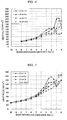
- Fig. 6 shows heat flux measurement results from the quenching nozzles under a condition that the nozzle diameter is ⁇ 8 and the chamber pressure is 0.65MPa.
- Fig. 7 shows heat flux measurement results from the quenching nozzles under a condition that the nozzle diameter is ⁇ 4 and the chamber pressure is 0.3MPa.
- Fig. 8 shows an example of heat flux measurement results from the quenching nozzles under a condition that the nozzle diameter is ⁇ 1 and the chamber pressure is 0.65MPa.
- the vertical axis refers to heat flux
- the horizontal axis refers to dimensionless distance obtained by dividing the distance between glass and nozzle by the exit diameter d of quenching nozzle.
- heat flux value changes complicatedly by various conditions.
- Heat transfer coefficient and impact pressure change by the difference of distance between the nozzle exit emitted the air and the impact surface of the glass surface, and the phenomena of both are completely different by the pressure in the chamber. That is, in the case of underexpansion jet flow, even if the distance to the impact surface is shortened, heat transfer coefficient does not necessarily improve. In some cases, it improves by the enlargement. Even if the pressure in the chamber is increased, an adverse effect may be caused depending on the distance to the impact surface of the glass.
- the difference of the surface compressive stresses in a thermally-tempered glass surface is 20MPa or less. If the difference of the surface compressive stresses in a thermally-tempered glass surface exceeds 20MPa, the variation of fragment density in the tempered glass becomes greater, and there occur many cases in which the specifications of tempered glasses are not satisfied. Preferably, it is 15MPa or less. Since the nozzle length also has an influence less than the above-mentioned factors, it is preferably in a range of 50-250mm.
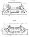
- a thermally tempered glass was produced by using a nozzle 1 group of a shape shown in Figs. 2A and 2B having an inner diameter d of 3mm and a length L of 100mm for a relatively flat region forming portion and by using a nozzle 2 group of a shape shown in Figs. 2A and 2B having an inner diameter d of 4mm and a length L of 100-130mm for a curved region forming portion (curved surface radius: ⁇ 500mm).
- Each nozzle communicates with a high-pressure air supply apparatus through a blast head 3. The distance between glass and nozzle upon this was based on about 30mm, and the chamber pressure was adjusted to 0.4MPa.
- the fragment density (the number/25 cm 2 ) at the relatively flat region forming portion was about 100, and that even at the curved region forming portion was about 60.
- This result meets the specification as a tempered glass.
- the surface compressive stress of this tempered glass was measured, it was 90MPa at a place where the maximum value was obtained and 80MPa even at a place where the minimum value was obtained. The difference was 10MPa.
- a curved 2.3mm thick glass having dimensions of 490x820 (mm).
- a thermally tempered glass was produced by using a nozzle group having an inner diameter of 3mm and a length of 100mm for a relatively flat region forming portion and by using a nozzle group having an inner diameter of 4mm and a length of 150-200mm for a curved region forming portion (curved surface radius: ⁇ 250mm).
- the distance between glass and nozzle upon this was based on about 25mm, and the chamber pressure was adjusted to 0.5MPa.
- the fragment density (the number/25 cm 2 ) at the relatively flat region forming portion was about 350, and that even at the curved region forming portion was about 250.
- This result meets the specification as a tempered glass.
- the surface compressive stress of this tempered glass was measured, it was 135MPa at a place where the maximum value was obtained and 120MPa even at a place where the minimum value was obtained. The difference was 15MPa.
- a thermally tempered glass was produced by using a nozzle group having an inner diameter of 2.5mm and a length of 100mm for a relatively flat region forming portion, by using a nozzle group having an inner diameter 3mm and a length of 150-200mm for a curved region forming portion A (curved surface radius: ⁇ 500mm), and by using a nozzle group having an inner diameter of 4mm and a length of 150-200mm for a curved region forming portion B (curved surface radius: ⁇ 250mm).
- the distance between glass and nozzle upon this was based on about 25mm, and the chamber pressure was adjusted to 0.55MPa.
- the fragment density (the number/25 cm 2 ) at the relatively flat region forming portion was about 150, and that even at the curved region forming portion was about 80.
- This result meets the specification as a tempered glass.
- the surface compressive stress of this tempered glass was measured, it was 100MPa at a place where the maximum value was obtained and 90MPa even at a place where the minimum value was obtained. The difference was 10MPa.
- a thermally tempered glass was produced by using a nozzle group having exit diameters of 3mm and 5mm for a relatively flat region forming portion, by using a nozzle group having exit diameters of 2.5mm and 4mm for a curved region forming portion A (curved surface radius: ⁇ 500mm), and by using a nozzle group having exit diameters of 2mm, 3mm and 4mm for a curved region forming portion B (curved surface radius: ⁇ 250mm).
- the pressure of impact jet flow upon this was 0.4MPa at the relatively flat region forming portion, 0.5MPa at the curved region forming portion A, and 0.65MPa at the curved region forming portion B.
- the distance Z between glass and nozzle was based on 20mm in the case of the nozzle (exit diameter: 3mm) and 25mm in the case of the nozzle (exit diameter: 5mm) of the flat region forming portion, on 16mm in the case of the nozzle (exit diameter: 2.5mm) and 18mm in the case of the nozzle (exit diameter: 4mm) of the curved region forming portion A, and on 16mm in the case of the nozzle (exit diameter: 2mm), 20mm in the case of the nozzle (exit diameter: 3mm) and 24mm in the case of the nozzle (exit diameter: 4mm) of the curved region forming portion B.
- the fragment density (the number/25 cm 2 ) was about 160 at the relatively flat region forming portion and about 100 even at the curved region forming portion.
- This result meets the specification as a tempered glass.
- the surface compressive stress of this tempered glass was measured, it was 100MPa at a place where the maximum value was obtained and 90MPa even at a place where the minimum value was obtained. The difference was 10MPa.
- a thermally tempered glass was produced by uniformly arranging a nozzle 1 group (inner diameter d: 3mm; length L: 100mm) having a shape shown in Figs. 2A and 2B.
- nozzles 4 having bent ends were used for the curvature-forming portion.
- Each nozzle communicates with a high-pressure air supply apparatus through a blast head 3. The distance between glass and nozzle was based on 30mm, and the chamber pressure was adjusted to 0.4MPa.
- the fragment density (the number/25 cm 2 ) at the relatively flat region forming portion was about 100, and that at the curved region forming portion was 45. Therefore, the specification as a thermally tempered glass could not be satisfied.
- the surface compressive stress of this tempered glass was measured, it was 90MPa at a place where the maximum value was obtained and 65MPa even at a place where the minimum value was obtained. The difference was 25MPa.
- the fragment density (the number/25 cm 2 ) at the relatively flat region forming portion was about 330, and that at the curved region forming portion was about 80.
- a breaking starting point was set at a center portion, a spline having a length of 80mm occurred near to the curvature forming portion. Therefore, it was necessary to consider that the specification as a thermally tempered glass was not satisfied.
- the surface compressive stress of this tempered glass was measured, it was 135MPa at a place where the maximum value was obtained and 110MPa even at a place where the minimum value was obtained. The difference was 25MPa.
- a curved 2.3mm thick glass having a curved region forming portion A (curved surface radius: ⁇ 500mm) and a curved region forming portion B (curved surface radius: ⁇ 250mm) having dimensions of 540x1150 (mm).
- a tempered glass was produced by using only a nozzle group (inner diameter: 2.5mm; length: 100mm). The distance between glass and nozzle upon this was based on 25mm, and the chamber pressure was adjusted to 0.55MPa.
- a 1.8mm thick glass having dimensions of 540x1150 (mm) was prepared.
- a surface stress meter made by Toshiba Glass Co. was used.
- the quenching starting temperature in the production of a thermally tempered glass was set to 680°C.
Landscapes
- Chemical & Material Sciences (AREA)
- Physics & Mathematics (AREA)
- Thermal Sciences (AREA)
- Engineering & Computer Science (AREA)
- Materials Engineering (AREA)
- Organic Chemistry (AREA)
- Mathematical Physics (AREA)
- Re-Forming, After-Treatment, Cutting And Transporting Of Glass Products (AREA)
Abstract
The invention relates, in case that a thermally tempered glass is
produced by allowing an impact jet flow from quenching nozzles to blow
against the glass, to a process for producing a curved shape, thermally
tempered glass, characterized in that a quenching is conducted by
simultaneously using at least two types of quenching nozzles having different
exit diameters of the quenching nozzles. Furthermore, the invention relates
to a curved, thermally tempered glass produced by this process and to an
apparatus for producing the thermally tempered glass. In the invention, it is
preferable that a exit diameter d is from 1mm to 8mm, a distance Z between
the nozzle and the glass is 1 to 80mm, a chamber pressure P is in a range of 0.1
to 0.8MPa, and a heat flux difference is 150kW/m2 or less. Furthermore, in
the thermally tempered glass, it is preferable that a difference of surface
compressive stress values within a glass surface is 20MPa or less.
Description
The present invention relates to so-called thermally tempered glasses
produced by air-quench method, particularly thermally-tempered curved
glasses of thicknesses of 2.5mm or less, their production process and their
production apparatus.
From the viewpoint of resource saving and energy saving, there is a
progress to make thermally tempered glasses have thinner thicknesses and
greater degrees of tempering. As means for this, chemical strengthening
method and physical tempering method are mainly used. Chemical
strengthening method is a method in which the glass surface is provided with a
compressive stress by using ion exchange, crystallization, the difference in
thermal expansion coefficient, etc., and tempered glasses by that method are
called chemically strengthened glasses. Chemical strengthening method is
suitable for strengthening thin plates having plate thicknesses of 3mm or less,
particularly 2mm or less. Since the thickness of the compressive stress layer
of chemically strengthened glasses is very thin, a problem of scratch strength
tends to occur. Therefore, there is a defect that the location for its use is
limited.
In contrast with this, as tempered glasses by physical tempering
method are also called thermally tempered glasses, they are produced by
quenching a glass heated near to the softening point, from its surface. In the
case of thermally tempered glass, it has a compressive stress layer that is
about 1/6 of the plate thickness and therefore has an advantage that a problem
of scratch strength does not tend to occur. As production process of thermally
tempered glasses, there are many uses of so-called air-quench tempering
method using the air as a quenching medium from the reasons in terms of the
production cost and safety, and thermally tempered glasses produced are also
called air-quench tempered glasses.
Thermally tempered glass is produced by using the temperature
difference and the viscous flow within the glass after heating in a furnace.
Therefore, in case that a thermally tempered glass is increased in the degree of
tempering, it is known that the following two methods are mainly used. One
is to increase as high as possible the glass temperature at the time of the
quenching starts. Another is to have a greater temperature difference
between the surface layer and the inner layer upon quenching.
By having a higher glass temperature at the start of the quenching, it
is possible to increase the degree of tempering and to produce tempered glasses
of thin plates. Furthermore, it is possible to have less glass failure during the
production. However, when the glass temperature is too high, the glass
deforms, and there occurs a critical problem in which a predetermined shape
cannot be obtained. Therefore, in the case of increasing the degree of
tempering of tempered glasses, only a method for making the glass
temperature higher has a limitation.
On the other hand, with respect to having a greater glass inside
temperature difference between the surface layer and the inner layer upon
quenching, it can be explained by the concept of making Biot's number greater.
Biot's number is a dimensionless number represented by ((heat transfer
coefficient)x(plate thickness)/(heat conductivity)). It is possible to increase
the glass tempering degree by making this Biot's number greater. That is, it
is possible to increase the glass tempering degree by having a greater heat
transfer coefficient, a greater plate thickness and a less heat conductivity.
However, in the case of having a less plate thickness of a tempered glass, that
is, in the case of producing a thin plate tempered glass, since heat conductivity
of glass is constant in general, it is necessary to make heat transfer coefficient
greater in order to make the numerator of Biot's number greater. Therefore,
in the case of producing a thin glass plate, a method of making heat transfer
coefficient greater is a main countermeasure.
In quenching using nozzle, relationships are experimentally found
between heat transfer coefficient and its quenching condition (for example, see
R.Gardon and J.Cobonpue, Heat Transfer between a Flat Plate and Jets of Air
Impinging on It, Int. Develop Heat Transfer, ASME (1962), pp454-460), such
as:
(h·rn )/λ=0.286Re0.625
Re=(Vg·rn )/ν
Vg=6.63Vn ·d/Z.
Where, h is heat transfer coefficient, λ is heat conductivity of the air, ν is
coefficient of kinematic viscosity of the air, Re is Reynolds number, rn is the
distance between nozzles, d is the nozzle diameter at the nozzle exit, Vn is flow
rate at the nozzle exit, Vg is flow rate on the glass surface, and Z is the
distance between the nozzle and the glass. The above-mentioned numerical
values exist in case that Z/d is greater than 8. However, as shown from the
forms of the above formulas, as a general method for having a greater
heat-transfer coefficient, it is effective to make the distance between the glass
and the nozzle exit shorter, to achieve the energy increase upon impingement
of the quenching air, etc., as well as to have a greater jet rate from the nozzle
(to have a greater jet pressure from the nozzle), to have a greater nozzle
diameter, and to increase the number of nozzles.
The trend of resource saving and energy saving in tempered glass has
another large trend of tempered glass shape complication. For example, as
the trend of having a more streamlined automobile shape progresses in order
to lower the automobile fuel consumption, and there is a demand for tempered
glasses to fit to such shapes. This movement progresses in many fields, not
only in automobile, but also in electric train, airplanes, etc. To satisfy a more
streamlined shape, there is a demand of making the tempered glass shape
more complex. We are in a condition that this demand must also be satisfied.
However, it is not easy to satisfy this demand. In particular, in a greatly
curved glass, it is very difficult to obtain a predetermined degree of tempering
at around its curved portions. Furthermore, as mentioned above, it is a very
difficult technique to satisfy this, since there is also a demand for thinner plate
tempered glasses.
In view of prior art, there are disclosed proposals, such as adjusting the
glass temperature in the direction along the plate width by an exhaust air used
in quenching (e.g., see Japanese Patent Laid-open Publication 2001-48561),
being characterized in the use of a tapered nozzle (e.g., see Japanese Patent
Examined Publication 6-76223), being equipped with first group nozzles jetting
a blower air and second group nozzles jetting a compressed air (e.g., Japanese
Patent Laid-open Publication 2001-26434), making a device to conform to a
curved plate glass, of which shape changes (e.g., see Japanese Patent
Laid-open Publication 7-29164), and limiting the width of a band-like region,
the maximum principal stress difference, the average surface compressive
stress, etc. (e.g., see Japanese Patent Laid-open Publication 11-199257).
Furthermore, the present applicant has shown a thermal tempering method by
a shock tube like use (e.g., see Japanese Patent Laid-open Publication
62-158128).
In the case of producing thermally tempered glasses of thicknesses of
2.5mm or less, particularly thin-plate tempered glasses of thicknesses of
2.3mm or less, it is difficult to say that production processes of thermally
tempered glasses are established by conventional methods of increasing glass
temperature upon tempering and/or methods of obtaining large heat transfer
coefficients. Therefore, we are in a condition that desired thermally tempered
glasses cannot be obtained. In particular, in the case of thermally tempered
glasses in the form of curved thin plate, this trend is outstanding.
That is, as a method for increasing heat transfer coefficient, it is
effective to shorten the distance between the glass and the nozzle exit, to
increase the impact energy of a quenching medium, etc., as well as to increase
the jetting speed from the nozzles (to increase the jetting pressure from the
nozzles), to enlarge the nozzle diameter, and to increase the number of nozzles.
However, a method of increasing the jetting speed from the nozzles or
shortening the distance to the glass causes jetting marks of the nozzles on the
glass, resulting in an optical problem. By a method of enlarging the nozzle
diameter or increasing the number of the nozzles, it is not possible to well
manage the airflow after its impingement against glass, since the
cross-sectional area occupied by the nozzles increases. As a result, it is not
possible to obtain a large heat transfer coefficient. Furthermore, it is not
practical to use a quenching medium other than the air in view of the
production cost. It is also limited to increase the glass temperature at the
start of the quenching.
It is not possible to retain a sufficient glass temperature by a method
disclosed in Japanese Patent Laid-open Publication 2001-48561.
Furthermore, it is not possible to obtain a large heat transfer coefficient even
by methods disclosed in Japanese Patent Examined Publication 6-76223 and
Japanese Patent Laid-open Publication 2001-26434. It is not possible to
obtain the above-mentioned thin-plate tempered glass even by the method
disclosed in Japanese Patent Laid-open Publication 7-29164, and in some cases
the degree of tempering even lowers. Furthermore, it is substantially
impossible to apply the method disclosed in Japanese Patent Laid-open
Publication 11-199257 to curved tempered glasses.
In view of the above-mentioned problems, the present invention
provides a thin-plate tempered glass, its tempering process and tempering
apparatus under a new concept. That is, the present invention provides, in
case that a thermally tempered glass is produced by allowing an impact jet
flow from a quenching nozzle to blow against the glass, a process for producing
a curved, thermally tempered glass, in which a quenching is conducted by
simultaneously using at least two types of quenching nozzles having different
exit diameters of the quenching nozzles.
Furthermore, the present invention provides a curved, thermally
tempered glass produced by the above process.
Still furthermore, the present invention provides a production process
of the above thermally tempered glass.
The present inventors found that the conventional heat transfer
concept must partially be modified and developed a new production process of
tempered glasses based on this modified concept, as a result of a detailed
examination on the flow of the air jetted from the nozzles used in producing
tempered glasses. That is, we have found that the relationship between the
jet flow from the quenching nozzles and the heat transfer coefficient is not so
simple as discussed conventionally, but is a complicated phenomenon that is
influenced by the nozzle exit diameter and shape, the impact jet flow pressure,
the distance between the nozzle exit and glass, etc. With this, it was made
possible by means meeting this phenomenon to produce curved, thin-plate
tempered glasses of a thickness of 2.5mm or less that had been considered to be
difficult. In particular, it is effective for curved, thin-plate tempered glasses of
a thickness of 2.3mm or less, of which production has been extremely difficult
so far.
It was made possible by the present invention to stably produce
thin-plate tempered glasses of thicknesses of 2.5mm or less that had been
difficult, particularly curved tempered glasses of 2.3mm or less.
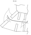
In Fig. 1 to Fig. 8, the reference numerals and reference signs 1, 2, 3, 4,
L and d respectively represent a quenching nozzle, a quenching nozzle, a blast
head, a quenching nozzle, length of a nozzle, and inner diameter of a nozzle.
As shown in Fig. 1, when a high-pressure air is allowed to flow through
an elongated thin nozzle, an underexpansion jet flow occurs under some
conditions. With this, the impact pressure changes and heat transfer
coefficient changes depending on the difference of the distance between the
nozzles and the impact surface of the glass plate surface.
The present invention is a process for producing a curved, thermally
tempered glass, in which a quenching is conducted by simultaneously using at
least two types of quenching nozzles having different exit diameters of the
quenching nozzles, in case that thermally tempered glasses are produced by
allowing the impact jet flow from the quenching nozzles to blow against glass.
It is not possible to obtain superior tempered glasses by only changing the
nozzle length relative to curved glasses and by using nozzles of only one exit
diameter type as conducted hitherto.
Furthermore, it is preferable that the exit diameter d of quenching
nozzle is from 1mm to 8mm, that the distance Z between quenching nozzles
and glass is from 1mm to 80mm, and that the pressure P of a chamber
communicating with the quenching nozzle is from 0.1MPa to 0.8MPa. Herein,
the exit diameter d of quenching nozzle refers to the diameter at the exit of the
nozzle.
If the exit diameter d of the quenching nozzle is less than 1mm, it is
necessary to provide many nozzles for maintaining its quenching capability.
Therefore, its management becomes difficult. On the other hand, the exit
diameter d of the quenching nozzle exceeds 8mm, the quenching capability
tends to lower, and it becomes difficult to conduct a uniform quenching. More
preferably, it is from 2mm to 6mm.
It is preferable that the distance Z between the quenching nozzles and
the glass is from 1mm to 80mm. If the distance Z between the quenching
nozzles and the glass is less than 1mm, marks of the impact jet flow ejected
from the nozzle remain. On the other hand, if it exceeds 80mm, it is not
possible to obtain a tempered glass of a thin plate thickness. More preferably,
it is from 3mm to 50mm. The distance Z between the glass quenching nozzles
and the glass refers to the distance between the nozzle exit and the glass plate.
The quenching nozzles are connected with a chamber generally called a
blast head. Upstream of the chamber, a compressor or high-pressure blower
is provided. It is preferable that the pressure P of the chamber connected to
the quenching nozzles is from 0.1MPa to 0.8MPa. If the pressure P of the
chamber connected to the quenching nozzles is lower than 0.1MPa, it is
difficult to obtain a thermally tempered glass of a thickness of 2.5mm or less.
On the other hand, it is difficult to obtain a pressure exceeding 0.8Pa by a
normal apparatus, resulting in a large cost increase. Preferably it is from
0.2MPa to 0.75MPa.
It is preferable to adjust the heat flux difference within the glass
surface to 150kW/m2 by properly changing the distance Z between nozzle and
glass, the pressure P of the chamber communicating with the quenching
nozzles, and the diameter d of the quenching nozzle. If it exceeds 150kW/m2,
the resulting thermally tempered glass becomes low in uniformity. With this,
there may occur problems at a breaking test, for example, the maximum value
of breaking at a breaking start point is over, and in contrast the minimum
value tends to become too small at another breaking start point. Furthermore,
there may occur dangerous sharp pieces called splines.
It is preferable to set the distance Z between quenching nozzle and
glass, the pressure P of impact jet flow, and the quenching nozzle diameter d
such that the difference of the surface compressive stress values of a thermally
tempered glass is 20MPa or less. If the difference of the surface compressive
stress values of a thermally tempered glass exceeds 20MPa, the resulting
thermally tempered glass becomes low in uniformity. It is often to adjust heat
flux upon quenching to 150kW/m2 or less under a normal production condition
in order to adjust the difference of the surface compressive stress values of a
thermally tempered glass to 20MPa or less. However, in case that the glass
temperature upon quenching start is low, it is preferable to provide a difference
smaller than the above-mentioned value.
Furthermore, it is a curved, thermally tempered glass produced by
either of the above-mentioned processes. This thermally tempered glass is
2.5mm or less that has been extremely difficult hitherto. Furthermore, it is
possible to produce a curved, thermally tempered glass of 2.3mm or less.
It is preferable that the difference between the surface compressive
stress values within the glass surface is 20MPa or less. If it is less than this
value, it is uniform as a thermally tempered glass, and it does not become a
serious problem against various loads.
Still furthermore, it is preferable that at least two types of quenching
nozzles, of which exit diameter d is from 1mm to 8mm, are simultaneously
provided, that there is provided a system controlled in a manner that the
pressure P of the chamber communicating with the quenching nozzles is from
0.1MPa to 0.8MPa, and that there is provided a production apparatus of
curved, thermally tempered glasses using quenching nozzles that is capable of
adjusting the distance Z between quenching nozzle and glass to 1mm to 80mm.
According to the present apparatus, it is decided by overall judging the
pressure P of the impact jet flow from the quenching nozzles, the distance Z
between quenching nozzle and glass, and the exit diameter d of at least two
types of quenching nozzles that is from 1mm to 8mm.
Furthermore, it is preferable to arrange quenching nozzles of different
exit diameters at a curved-region forming portion and a flat region-forming
portion such that the difference between the surface compressive stress values
within the glass surface becomes 20MPa or less. In many cases in the curved
region-forming portion, it is difficult to put compressive stress. Therefore, it
is necessary to make heat flux greater than that of the flat region portion.
With this, to be a production apparatus of thermally tempered glasses, in
which quenching nozzles of different exit diameters can be arranged, is
preferable.
Furthermore, to be a production apparatus of thermally tempered
glasses, in which at least two types of quenching nozzles of different exit
diameters are arranged, is preferable. The thinner the glass plate is more
difficult to uniform quenching. Therefore, a production apparatus of
thermally tempered glasses, in which at least two types of quenching nozzles
can be combined even in the flat region portion, is preferable.
Furthermore, when described in detail, it is necessary to provide two
types of quenching nozzles having exit diameters that are different by 10% at
the minimum in opening area. On the other hand, its upper limit is 500% in
opening area. Desirably, it is preferable to use quenching nozzles that are
different by 20% to 300% in opening area. It becomes important to
appropriately arrange nozzles of a large heat transfer coefficient and nozzles of
a heat transfer coefficient smaller than that by suitably selecting the nozzle
inner diameter, the nozzle length, the distance between nozzle and the impact
surface of the glass plate surface, and the pressure of the impact jet flow. In
general, nozzles of a large heat transfer coefficient are used at a place that
requires a large quenching capacity, for example, a sharply curved place. It is
preferable that the impact jet flow is underexpansion jet flow. To be
underexpansion jet flow is important to increase heat transfer coefficient.
In arranging the quenching nozzles, it is also necessary to consider the
temperature distribution within the glass surface besides the degree of
curvature. This is because it is always true to have uneven temperature of
the glass surface even if the heating is conducted under similar conditions. In
general, it is possible to obtain uniform thermally tempered glasses with a
greater number of types of the quenching nozzles. However, the nozzle
arrangement and the quenching condition are limited contrary. It is thus
necessary to overall consider not only the shape and plate thickness of the
target thermally tempered glass, but also the facility specification, quenching
condition, etc.
Although the quenching nozzle preferably has a general thin shape, for
example, it may be a nozzle, of which inner diameter changes, as Laval nozzle.
However, in case that its inner diameter changes greatly, it results in a
condition similar to that wherein a large diameter nozzle is used. Thus, it is
not efficient in view of the airflow after quenching.
Fig. 6 shows heat flux measurement results from the quenching nozzles
under a condition that the nozzle diameter is 8 and the chamber pressure is
0.65MPa. Fig. 7 shows heat flux measurement results from the quenching
nozzles under a condition that the nozzle diameter is 4 and the chamber
pressure is 0.3MPa. Fig. 8 shows an example of heat flux measurement
results from the quenching nozzles under a condition that the nozzle diameter
is 1 and the chamber pressure is 0.65MPa. In either of them, the vertical
axis refers to heat flux, and the horizontal axis refers to dimensionless distance
obtained by dividing the distance between glass and nozzle by the exit
diameter d of quenching nozzle.
In such manner, the heat flux value changes complicatedly by various
conditions. Heat transfer coefficient and impact pressure change by the
difference of distance between the nozzle exit emitted the air and the impact
surface of the glass surface, and the phenomena of both are completely
different by the pressure in the chamber. That is, in the case of
underexpansion jet flow, even if the distance to the impact surface is shortened,
heat transfer coefficient does not necessarily improve. In some cases, it
improves by the enlargement. Even if the pressure in the chamber is
increased, an adverse effect may be caused depending on the distance to the
impact surface of the glass.
As a method for determining the degree of tempering of thermally
tempered glasses, there is widely proposed a method of which estimation is
conducted from breaking test (JIS R3205) and surface compressive stress (JIS
R3222). In breaking test, the number of breakings in a 5cm square is
expressed as the fragment density. In case that a fragment is in a 5cm square,
it is counted as 1. In case that it is on the side, 0.5 is taken. The greater the
fragment density, the greater the degree of tempering. In the case of a normal
thermally-tempered glass, the fragment density is required to be from 40 to
400. If it exceeds 400, although it is placed outside of the category of general
thermally-tempered glasses, it may be used as a super-tempered glass in some
cases. Although the value of the surface compressive stress of tempered glass
is not limited, a tempered glass with a higher degree of tempering generally
has a greater value of the surface compressive stress.
It is necessary that the difference of the surface compressive stresses in
a thermally-tempered glass surface is 20MPa or less. If the difference of the
surface compressive stresses in a thermally-tempered glass surface exceeds
20MPa, the variation of fragment density in the tempered glass becomes
greater, and there occur many cases in which the specifications of tempered
glasses are not satisfied. Preferably, it is 15MPa or less. Since the nozzle
length also has an influence less than the above-mentioned factors, it is
preferably in a range of 50-250mm.
In the following, the present invention is explained in detail by
examples, but the present invention is not limited to these examples.
There was prepared a curved 2.3mm thick glass having dimensions of
490x820 (mm). As shown in Figs. 3A and 3B, a thermally tempered glass was
produced by using a nozzle 1 group of a shape shown in Figs. 2A and 2B having
an inner diameter d of 3mm and a length L of 100mm for a relatively flat
region forming portion and by using a nozzle 2 group of a shape shown in Figs.
2A and 2B having an inner diameter d of 4mm and a length L of 100-130mm
for a curved region forming portion (curved surface radius: ~500mm). Each
nozzle communicates with a high-pressure air supply apparatus through a
blast head 3. The distance between glass and nozzle upon this was based on
about 30mm, and the chamber pressure was adjusted to 0.4MPa.
As a result of an air-quench tempering treatment under this quenching
condition, the fragment density (the number/25 cm2) at the relatively flat
region forming portion was about 100, and that even at the curved region
forming portion was about 60. This result meets the specification as a
tempered glass. When the surface compressive stress of this tempered glass
was measured, it was 90MPa at a place where the maximum value was
obtained and 80MPa even at a place where the minimum value was obtained.
The difference was 10MPa.
There was prepared a curved 2.3mm thick glass having dimensions of
490x820 (mm). A thermally tempered glass was produced by using a nozzle
group having an inner diameter of 3mm and a length of 100mm for a relatively
flat region forming portion and by using a nozzle group having an inner
diameter of 4mm and a length of 150-200mm for a curved region forming
portion (curved surface radius: ~250mm). The distance between glass and
nozzle upon this was based on about 25mm, and the chamber pressure was
adjusted to 0.5MPa.
As a result of an air-quench tempering treatment under this quenching
condition, the fragment density (the number/25 cm2) at the relatively flat
region forming portion was about 350, and that even at the curved region
forming portion was about 250. This result meets the specification as a
tempered glass. When the surface compressive stress of this tempered glass
was measured, it was 135MPa at a place where the maximum value was
obtained and 120MPa even at a place where the minimum value was obtained.
The difference was 15MPa.
There was prepared a curved 2.3mm thick glass having dimensions of
540x1150 (mm). A thermally tempered glass was produced by using a nozzle
group having an inner diameter of 2.5mm and a length of 100mm for a
relatively flat region forming portion, by using a nozzle group having an inner
diameter 3mm and a length of 150-200mm for a curved region forming portion
A (curved surface radius: ~500mm), and by using a nozzle group having an
inner diameter of 4mm and a length of 150-200mm for a curved region forming
portion B (curved surface radius: ~250mm). The distance between glass and
nozzle upon this was based on about 25mm, and the chamber pressure was
adjusted to 0.55MPa.
As a result of an air-quench tempering treatment under this quenching
condition, the fragment density (the number/25 cm2) at the relatively flat
region forming portion was about 150, and that even at the curved region
forming portion was about 80. This result meets the specification as a
tempered glass. When the surface compressive stress of this tempered glass
was measured, it was 100MPa at a place where the maximum value was
obtained and 90MPa even at a place where the minimum value was obtained.
The difference was 10MPa.
In order to thermally temper a curved 1.8mm thick glass having
dimensions of 540x1150 (mm), as shown in Figs. 4A and 4B, there was used a
quenching apparatus having different nozzle exit diameters and different
nozzle lengths. A thermally tempered glass was produced by using a nozzle
group having exit diameters of 3mm and 5mm for a relatively flat region
forming portion, by using a nozzle group having exit diameters of 2.5mm and
4mm for a curved region forming portion A (curved surface radius: ~500mm),
and by using a nozzle group having exit diameters of 2mm, 3mm and 4mm for
a curved region forming portion B (curved surface radius: ~250mm). The
pressure of impact jet flow upon this was 0.4MPa at the relatively flat region
forming portion, 0.5MPa at the curved region forming portion A, and 0.65MPa
at the curved region forming portion B. The distance Z between glass and
nozzle was based on 20mm in the case of the nozzle (exit diameter: 3mm) and
25mm in the case of the nozzle (exit diameter: 5mm) of the flat region forming
portion, on 16mm in the case of the nozzle (exit diameter: 2.5mm) and 18mm in
the case of the nozzle (exit diameter: 4mm) of the curved region forming
portion A, and on 16mm in the case of the nozzle (exit diameter: 2mm), 20mm
in the case of the nozzle (exit diameter: 3mm) and 24mm in the case of the
nozzle (exit diameter: 4mm) of the curved region forming portion B.
As a result of an air-quench tempering treatment of the
above-mentioned quenching apparatus under a heating condition where the
furnace temperature was 680°C and the furnace time was 180 seconds, the
fragment density (the number/25 cm2) was about 160 at the relatively flat
region forming portion and about 100 even at the curved region forming
portion. This result meets the specification as a tempered glass. When the
surface compressive stress of this tempered glass was measured, it was
100MPa at a place where the maximum value was obtained and 90MPa even
at a place where the minimum value was obtained. The difference was
10MPa.
There was prepared a curved 2.3mm thick glass (curved surface radius:
~500mm) having dimensions of 490x820 (mm). As shown in Figs. 5A and 5B,
a thermally tempered glass was produced by uniformly arranging a nozzle 1
group (inner diameter d: 3mm; length L: 100mm) having a shape shown in Figs.
2A and 2B. Upon this, nozzles 4 having bent ends were used for the
curvature-forming portion. Each nozzle communicates with a high-pressure
air supply apparatus through a blast head 3. The distance between glass and
nozzle was based on 30mm, and the chamber pressure was adjusted to 0.4MPa.
In case that an air-quench tempering treatment was conducted on the
2.3mm thick glass under this quenching condition, the fragment density (the
number/25 cm2) at the relatively flat region forming portion was about 100,
and that at the curved region forming portion was 45. Therefore, the
specification as a thermally tempered glass could not be satisfied. When the
surface compressive stress of this tempered glass was measured, it was 90MPa
at a place where the maximum value was obtained and 65MPa even at a place
where the minimum value was obtained. The difference was 25MPa.
There was prepared a curved 2.3mm thick glass (curved surface radius:
~250mm) having dimensions of 490x820 (mm). A thermally tempered glass
was produced by using only a nozzle group (inner diameter: 3mm; length:
100mm). The distance between glass and nozzle upon this was based on
25mm, and the chamber pressure was adjusted to 0.5MPa.
As a result of an air-quench tempering treatment under this quenching
condition, the fragment density (the number/25 cm2) at the relatively flat
region forming portion was about 330, and that at the curved region forming
portion was about 80. However, when a breaking starting point was set at a
center portion, a spline having a length of 80mm occurred near to the
curvature forming portion. Therefore, it was necessary to consider that the
specification as a thermally tempered glass was not satisfied. When the
surface compressive stress of this tempered glass was measured, it was
135MPa at a place where the maximum value was obtained and 110MPa even
at a place where the minimum value was obtained. The difference was
25MPa.
There was prepared a curved 2.3mm thick glass (having a curved
region forming portion A (curved surface radius: ~500mm) and a curved region
forming portion B (curved surface radius: ~250mm)) having dimensions of
540x1150 (mm). A tempered glass was produced by using only a nozzle group
(inner diameter: 2.5mm; length: 100mm). The distance between glass and
nozzle upon this was based on 25mm, and the chamber pressure was adjusted
to 0.55MPa.
As a result of an air-quench tempering treatment under this quenching
condition, only 40 was obtained at the curved region forming portion.
Therefore, the production was conducted by raising the chamber pressure to
0.65MPa.
As a result of this, a fragment density of about 60 was obtained even at
the curved region forming portion. However, dimples remained on the glass
as a result of raising the pressure. Thus, the specification as a tempered glass
in terms of optical characteristics was not satisfied. When the surface
compressive stress of this tempered glass was measured, it was 110MPa at a
place where the maximum value was obtained and 80MPa even at a place
where the minimum value was obtained. The difference was 30MPa.
A 1.8mm thick glass having dimensions of 540x1150 (mm) was
prepared. The production of a thermally tempered glass, similar to that of
Example 4, was tried under a condition that all of the quenching nozzles were
adjusted to have an exit diameter of 3mm, a distance between nozzle and glass
of 40mm, and an impact jet flow pressure of 0.4MPa.
However, even if the breaking test was conducted, a fragmentation
phenomenon was not shown, as in a non-tempered glass. Therefore, the
impact jet flow pressure was raised to 0.6MPa, and the distance between
nozzle and glass was shortened to 20mm. As a result of this, a fragmentation
phenomenon was shown at the flat region. However, a coarse breaking
portion (fragment density: 12) occurred at the curved region forming portion B.
Furthermore, as the entirety was reviewed, the fragment density varied
greatly from ten-odd to 80.
Regarding the surface compressive stress of glass, a surface stress
meter made by Toshiba Glass Co. was used. The quenching starting
temperature in the production of a thermally tempered glass was set to 680°C.
As shown by the above results, a high value in jet pressure from nozzle
and a short distance between nozzle and glass do not necessarily raise heat
transfer coefficient, and it was extremely difficult to produce curved thin-plate
tempered glasses with high quality. However, the production of curved,
thin-plate tempered glasses was made possible under the condition of the
present invention, and the production yield also became stable. The fact that
the jet flow itself was an underexpansion jet flow in the examples was
confirmed by visualization using a double exposure holographic interferometry.
Claims (9)
- In case that a thermally tempered glass is produced by allowing an impact jet flow from quenching nozzles to blow against the glass, a process for producing a curved, thermally tempered glass, characterized in that a quenching is conducted by simultaneously using at least two types of quenching nozzles having different exit diameters of the quenching nozzles.
- A process for producing a curved, thermally tempered glass according to claim 1, characterized in that an exit diameter d of the quenching nozzle is from 1mm to 8mm, that a distance Z between the quenching nozzle and the glass is from 1mm to 80mm, and that a pressure P of a chamber communicating with the quenching nozzle is from 0.1 to 0.8MPa.
- A process for producing a curved, thermally tempered glass according to claim 1 or claim 2, characterized in that a heat flux difference within a glass surface is adjusted to 150kW/m2 or less by properly changing a distance Z between the nozzle and the glass, a pressure P of a chamber, and a diameter d of the quenching nozzle.
- A process for producing a curved, thermally tempered glass according to any one of claims 1 to 3, characterized in that a distance Z between the quenching nozzle and the glass, a pressure P of a chamber, and a diameter d of the quenching nozzle are set, thereby adjusting a difference of surface compressive stress values of the thermally tempered glass to 20MPa or less.
- A curved, thermally tempered glass characterized in that it has been produced by any one process of claims 1 to 4.
- A curved, thermally tempered glass according to claim 5, characterized in that a difference of surface compressive stress values within a glass surface
- An apparatus for producing a curved, thermally tempered glass according to claim 5 or claim 6, characterized in that it is simultaneously provided with at least two kinds of quenching nozzles having an exit diameter D of 1mm to 8mm, that it has a system controlled to make a chamber pressure P have a value of 0.1MPa to 0.8MPa, and that it uses a quenching nozzle capable of adjusting a distance Z between the quenching nozzle and the glass to a range of 1-80mm.
- An apparatus for producing a curved, thermally tempered glass according to claim 7, characterized in that quenching nozzles having different exit diameters are arranged at a curved region forming portion and a flat region forming portion, thereby adjusting a difference of surface compressive stress values within a glass surface to 20MPa or less.
- An apparatus for producing a curved, thermally tempered glass according to claim 7, characterized in that at least two kinds of quenching nozzles of different exit diameters are arranged, thereby adjusting a difference of surface compressive stress values within a glass surface to 20MPa or less.
Applications Claiming Priority (5)
| Application Number | Priority Date | Filing Date | Title |
|---|---|---|---|
| JP2002258355 | 2002-09-04 | ||
| JP2002258355 | 2002-09-04 | ||
| JP2003301229 | 2003-08-26 | ||
| JP2003301229A JP4397196B2 (en) | 2002-09-04 | 2003-08-26 | Thermally tempered glass and manufacturing method and apparatus thereof |
| PCT/JP2003/011241 WO2004026777A1 (en) | 2002-09-04 | 2003-09-03 | Thermally tempered glass, and method and apparatus for manufactuing the glass |
Publications (1)
| Publication Number | Publication Date |
|---|---|
| EP1547980A1 true EP1547980A1 (en) | 2005-06-29 |
Family
ID=32032852
Family Applications (1)
| Application Number | Title | Priority Date | Filing Date |
|---|---|---|---|
| EP03797543A Withdrawn EP1547980A1 (en) | 2002-09-04 | 2003-09-03 | Thermally tempered glass, and method and apparatus for manufactuing the glass |
Country Status (4)
| Country | Link |
|---|---|
| US (1) | US20060121281A1 (en) |
| EP (1) | EP1547980A1 (en) |
| JP (1) | JP4397196B2 (en) |
| WO (1) | WO2004026777A1 (en) |
Cited By (4)
| Publication number | Priority date | Publication date | Assignee | Title |
|---|---|---|---|---|
| EP2853517A1 (en) * | 2013-09-25 | 2015-04-01 | Glaston Finland Oy | Method and apparatus for tempering glass sheets |
| CN106316085A (en) * | 2015-07-01 | 2017-01-11 | 旭硝子株式会社 | Tempered glass sheet |
| WO2017020041A1 (en) * | 2015-07-30 | 2017-02-02 | Corning Incorporated | Thermally strengthened glass and related systems and methods |
| WO2017184414A1 (en) * | 2016-04-18 | 2017-10-26 | Corning Incorporated | Method of thermally tempering glass laminates using selective microwave heating and active cooling |
Families Citing this family (18)
| Publication number | Priority date | Publication date | Assignee | Title |
|---|---|---|---|---|
| US8234883B2 (en) * | 2005-11-29 | 2012-08-07 | Ppg Industries Ohio, Inc. | Apparatus and method for tempering glass sheets |
| US20090173106A1 (en) * | 2008-01-04 | 2009-07-09 | Boisselle Robert J | Glass tempering method and apparatus |
| CN101367619B (en) * | 2008-09-12 | 2011-10-05 | 江苏秀强玻璃工艺股份有限公司 | Manufacturing method of colorful crystal glass |
| CN102459105B (en) * | 2009-06-15 | 2015-02-04 | 皮尔金顿集团有限公司 | Improved glass tempering method and apparatus |
| JP2012000592A (en) * | 2010-06-18 | 2012-01-05 | Kobe Steel Ltd | Gas atomizer of high-temperature molten metal |
| US11097974B2 (en) | 2014-07-31 | 2021-08-24 | Corning Incorporated | Thermally strengthened consumer electronic glass and related systems and methods |
| US10611664B2 (en) | 2014-07-31 | 2020-04-07 | Corning Incorporated | Thermally strengthened architectural glass and related systems and methods |
| CA2956929A1 (en) | 2014-07-31 | 2016-02-04 | Corning Incorporated | Thermally tempered glass and methods and apparatuses for thermal tempering of glass |
| JP6112089B2 (en) * | 2014-09-17 | 2017-04-12 | カシオ計算機株式会社 | Heating apparatus, heating method, and three-dimensional formation system |
| US12338159B2 (en) | 2015-07-30 | 2025-06-24 | Corning Incorporated | Thermally strengthened consumer electronic glass and related systems and methods |
| JP6749997B2 (en) * | 2015-07-30 | 2020-09-02 | コーニング インコーポレイテッド | Thermally tempered consumer electronics glass and related systems and methods |
| KR102492060B1 (en) | 2016-01-12 | 2023-01-26 | 코닝 인코포레이티드 | Thin thermally and chemically strengthened glass-based articles |
| US11795102B2 (en) | 2016-01-26 | 2023-10-24 | Corning Incorporated | Non-contact coated glass and related coating system and method |
| WO2019040818A2 (en) | 2017-08-24 | 2019-02-28 | Corning Incorporated | Glasses with improved tempering capabilities |
| TWI785156B (en) | 2017-11-30 | 2022-12-01 | 美商康寧公司 | Non-iox glasses with high coefficient of thermal expansion and preferential fracture behavior for thermal tempering |
| DE102018123284A1 (en) * | 2018-09-21 | 2020-03-26 | sedak GmbH & Co. KG | Device for tempering glass panes |
| CN113727954A (en) | 2019-04-23 | 2021-11-30 | 康宁股份有限公司 | Glass laminates having defined stress profiles and methods of making same |
| US11697617B2 (en) | 2019-08-06 | 2023-07-11 | Corning Incorporated | Glass laminate with buried stress spikes to arrest cracks and methods of making the same |
Family Cites Families (8)
| Publication number | Priority date | Publication date | Assignee | Title |
|---|---|---|---|---|
| IE35468B1 (en) * | 1970-07-29 | 1976-02-18 | Triplex Safety Glass Co | Improvements in or relating to toughened glass sheets |
| JPS5888132A (en) * | 1981-11-18 | 1983-05-26 | Nippon Sheet Glass Co Ltd | Method and apparatus for manufacture of tempered glass |
| JPH0653592B2 (en) * | 1985-02-21 | 1994-07-20 | 旭硝子株式会社 | Manufacturing method of tempered glass |
| JPS62158128A (en) * | 1985-12-27 | 1987-07-14 | Central Glass Co Ltd | Method for toughening thin glass pane |
| JPH0613224Y2 (en) * | 1989-01-31 | 1994-04-06 | 日本板硝子株式会社 | Flat glass press mold |
| JPH0624995B2 (en) * | 1990-03-19 | 1994-04-06 | セントラル硝子株式会社 | Tempered glass manufacturing method |
| FI945082A0 (en) * | 1994-10-28 | 1994-10-28 | Risto Nikander | Foerfarande och anordning Foer justering av glashaerdningshuvudet |
| JP2001026434A (en) * | 1999-07-13 | 2001-01-30 | Nippon Sheet Glass Co Ltd | Device for rapidly cooling glass |
-
2003
- 2003-08-26 JP JP2003301229A patent/JP4397196B2/en not_active Expired - Fee Related
- 2003-09-03 US US10/526,550 patent/US20060121281A1/en not_active Abandoned
- 2003-09-03 EP EP03797543A patent/EP1547980A1/en not_active Withdrawn
- 2003-09-03 WO PCT/JP2003/011241 patent/WO2004026777A1/en not_active Ceased
Non-Patent Citations (1)
| Title |
|---|
| See references of WO2004026777A1 * |
Cited By (6)
| Publication number | Priority date | Publication date | Assignee | Title |
|---|---|---|---|---|
| EP2853517A1 (en) * | 2013-09-25 | 2015-04-01 | Glaston Finland Oy | Method and apparatus for tempering glass sheets |
| CN106316085A (en) * | 2015-07-01 | 2017-01-11 | 旭硝子株式会社 | Tempered glass sheet |
| CN106316085B (en) * | 2015-07-01 | 2020-12-25 | Agc株式会社 | Tempered glass plate |
| WO2017020041A1 (en) * | 2015-07-30 | 2017-02-02 | Corning Incorporated | Thermally strengthened glass and related systems and methods |
| WO2017184414A1 (en) * | 2016-04-18 | 2017-10-26 | Corning Incorporated | Method of thermally tempering glass laminates using selective microwave heating and active cooling |
| CN109071298A (en) * | 2016-04-18 | 2018-12-21 | 康宁股份有限公司 | The method that hot tempering is carried out to glass laminate using selective microwave heating and active cooling |
Also Published As
| Publication number | Publication date |
|---|---|
| US20060121281A1 (en) | 2006-06-08 |
| JP4397196B2 (en) | 2010-01-13 |
| WO2004026777A1 (en) | 2004-04-01 |
| JP2004115358A (en) | 2004-04-15 |
Similar Documents
| Publication | Publication Date | Title |
|---|---|---|
| EP1547980A1 (en) | Thermally tempered glass, and method and apparatus for manufactuing the glass | |
| US6881485B2 (en) | Tempered glass sheet and method therefor | |
| US4128690A (en) | Toughened glass sheets | |
| US4578102A (en) | Quenching or tempering by means of a two-phase jet | |
| JPS60145921A (en) | Glass enhancement and device therefor | |
| US8074473B2 (en) | Method for quenching formed glass sheets | |
| EP0781730A2 (en) | Toughened glass sheet | |
| EP1359230A1 (en) | Production method for steel plate and equipment therefor | |
| JPS5888132A (en) | Method and apparatus for manufacture of tempered glass | |
| EP2979769B1 (en) | Thick steel plate manufacturing method and manufacturing device | |
| CN119824198A (en) | Cooling device and cooling method for thick steel plate, and manufacturing equipment and manufacturing method for thick steel plate | |
| JP4266249B2 (en) | Tempered glass manufacturing equipment | |
| GB2232978A (en) | Method of tempering glass sheet by quenching | |
| KR102631495B1 (en) | Secondary cooling method of continuous casting cast steel | |
| EP4151326A1 (en) | Method for predicting temperature deviation in thick steel plate, method for controlling temperature deviation in thick steel plate, method for generating temperature deviation prediction model for thick steel plate, method for producing thick steel plate, and equipment for producing thick steel plate | |
| CN1075985A (en) | Method and device for heat treatment of rails | |
| CN101970364B (en) | Device and method for fluid removal after laser scoring | |
| CN107557550B (en) | A kind of preparation method of variable-strength high-strength steel auto parts | |
| JP2021193063A (en) | Method for tempering glass sheet and device for the same | |
| EP1167553A1 (en) | Rolls for disposing at entry side or exit side of quenching zone of continuous annealing furnace and quenching zone unit using rolls | |
| JPH11199257A (en) | Tempered glass plate, cooling method and cooling device for glass plate | |
| JPH0429615B2 (en) | ||
| CN108315532A (en) | Steel pipe water fog cooling means | |
| CN114075642A (en) | Water-cooled wall induction fusion welding following type surface strengthening method | |
| US5112377A (en) | Method of toughening glass sheet by quenching |
Legal Events
| Date | Code | Title | Description |
|---|---|---|---|
| PUAI | Public reference made under article 153(3) epc to a published international application that has entered the european phase |
Free format text: ORIGINAL CODE: 0009012 |
|
| 17P | Request for examination filed |
Effective date: 20050331 |
|
| AK | Designated contracting states |
Kind code of ref document: A1 Designated state(s): AT BE BG CH CY CZ DE DK EE ES FI FR GB GR HU IE IT LI LU MC NL PT RO SE SI SK TR |
|
| RBV | Designated contracting states (corrected) |
Designated state(s): DE FR GB |
|
| STAA | Information on the status of an ep patent application or granted ep patent |
Free format text: STATUS: THE APPLICATION HAS BEEN WITHDRAWN |
|
| 18W | Application withdrawn |
Effective date: 20110224 |