EP1547904A1 - Rack and pinion steering apparatus and method of manufacturing rack shaft - Google Patents
Rack and pinion steering apparatus and method of manufacturing rack shaft Download PDFInfo
- Publication number
- EP1547904A1 EP1547904A1 EP04106096A EP04106096A EP1547904A1 EP 1547904 A1 EP1547904 A1 EP 1547904A1 EP 04106096 A EP04106096 A EP 04106096A EP 04106096 A EP04106096 A EP 04106096A EP 1547904 A1 EP1547904 A1 EP 1547904A1
- Authority
- EP
- European Patent Office
- Prior art keywords
- rack
- shaft
- pinion
- rod
- shaped material
- Prior art date
- Legal status (The legal status is an assumption and is not a legal conclusion. Google has not performed a legal analysis and makes no representation as to the accuracy of the status listed.)
- Granted
Links
- 238000004519 manufacturing process Methods 0.000 title claims abstract description 17
- 238000005520 cutting process Methods 0.000 claims abstract description 24
- 238000010791 quenching Methods 0.000 claims abstract description 15
- 230000000171 quenching effect Effects 0.000 claims abstract description 12
- 239000000463 material Substances 0.000 claims description 25
- 229910000831 Steel Inorganic materials 0.000 claims description 11
- 239000010959 steel Substances 0.000 claims description 11
- 238000005496 tempering Methods 0.000 claims description 6
- 229910001149 41xx steel Inorganic materials 0.000 claims description 3
- 229910001567 cementite Inorganic materials 0.000 claims description 3
- KSOKAHYVTMZFBJ-UHFFFAOYSA-N iron;methane Chemical compound C.[Fe].[Fe].[Fe] KSOKAHYVTMZFBJ-UHFFFAOYSA-N 0.000 claims description 3
- 229910000734 martensite Inorganic materials 0.000 claims description 3
- 238000007670 refining Methods 0.000 claims description 3
- 229910000859 α-Fe Inorganic materials 0.000 claims description 3
- 238000010438 heat treatment Methods 0.000 description 5
- 238000000034 method Methods 0.000 description 5
- 230000007547 defect Effects 0.000 description 3
- 239000002184 metal Substances 0.000 description 2
- 230000004323 axial length Effects 0.000 description 1
- 238000007730 finishing process Methods 0.000 description 1
- 230000006698 induction Effects 0.000 description 1
- 238000005498 polishing Methods 0.000 description 1
Images

Classifications
-
- F—MECHANICAL ENGINEERING; LIGHTING; HEATING; WEAPONS; BLASTING
- F16—ENGINEERING ELEMENTS AND UNITS; GENERAL MEASURES FOR PRODUCING AND MAINTAINING EFFECTIVE FUNCTIONING OF MACHINES OR INSTALLATIONS; THERMAL INSULATION IN GENERAL
- F16H—GEARING
- F16H55/00—Elements with teeth or friction surfaces for conveying motion; Worms, pulleys or sheaves for gearing mechanisms
- F16H55/02—Toothed members; Worms
- F16H55/26—Racks
-
- B—PERFORMING OPERATIONS; TRANSPORTING
- B62—LAND VEHICLES FOR TRAVELLING OTHERWISE THAN ON RAILS
- B62D—MOTOR VEHICLES; TRAILERS
- B62D3/00—Steering gears
- B62D3/02—Steering gears mechanical
- B62D3/12—Steering gears mechanical of rack-and-pinion type
-
- B—PERFORMING OPERATIONS; TRANSPORTING
- B21—MECHANICAL METAL-WORKING WITHOUT ESSENTIALLY REMOVING MATERIAL; PUNCHING METAL
- B21K—MAKING FORGED OR PRESSED METAL PRODUCTS, e.g. HORSE-SHOES, RIVETS, BOLTS OR WHEELS
- B21K1/00—Making machine elements
- B21K1/76—Making machine elements elements not mentioned in one of the preceding groups
- B21K1/767—Toothed racks
-
- B—PERFORMING OPERATIONS; TRANSPORTING
- B23—MACHINE TOOLS; METAL-WORKING NOT OTHERWISE PROVIDED FOR
- B23P—METAL-WORKING NOT OTHERWISE PROVIDED FOR; COMBINED OPERATIONS; UNIVERSAL MACHINE TOOLS
- B23P15/00—Making specific metal objects by operations not covered by a single other subclass or a group in this subclass
- B23P15/14—Making specific metal objects by operations not covered by a single other subclass or a group in this subclass gear parts, e.g. gear wheels
-
- B—PERFORMING OPERATIONS; TRANSPORTING
- B62—LAND VEHICLES FOR TRAVELLING OTHERWISE THAN ON RAILS
- B62D—MOTOR VEHICLES; TRAILERS
- B62D3/00—Steering gears
- B62D3/02—Steering gears mechanical
- B62D3/12—Steering gears mechanical of rack-and-pinion type
- B62D3/126—Steering gears mechanical of rack-and-pinion type characterised by the rack
-
- C—CHEMISTRY; METALLURGY
- C21—METALLURGY OF IRON
- C21D—MODIFYING THE PHYSICAL STRUCTURE OF FERROUS METALS; GENERAL DEVICES FOR HEAT TREATMENT OF FERROUS OR NON-FERROUS METALS OR ALLOYS; MAKING METAL MALLEABLE, e.g. BY DECARBURISATION OR TEMPERING
- C21D9/00—Heat treatment, e.g. annealing, hardening, quenching or tempering, adapted for particular articles; Furnaces therefor
- C21D9/18—Heat treatment, e.g. annealing, hardening, quenching or tempering, adapted for particular articles; Furnaces therefor for knives, scythes, scissors, or like hand cutting tools
-
- Y—GENERAL TAGGING OF NEW TECHNOLOGICAL DEVELOPMENTS; GENERAL TAGGING OF CROSS-SECTIONAL TECHNOLOGIES SPANNING OVER SEVERAL SECTIONS OF THE IPC; TECHNICAL SUBJECTS COVERED BY FORMER USPC CROSS-REFERENCE ART COLLECTIONS [XRACs] AND DIGESTS
- Y10—TECHNICAL SUBJECTS COVERED BY FORMER USPC
- Y10T—TECHNICAL SUBJECTS COVERED BY FORMER US CLASSIFICATION
- Y10T29/00—Metal working
- Y10T29/49—Method of mechanical manufacture
- Y10T29/49462—Gear making
- Y10T29/49467—Gear shaping
- Y10T29/49476—Gear tooth cutting
-
- Y—GENERAL TAGGING OF NEW TECHNOLOGICAL DEVELOPMENTS; GENERAL TAGGING OF CROSS-SECTIONAL TECHNOLOGIES SPANNING OVER SEVERAL SECTIONS OF THE IPC; TECHNICAL SUBJECTS COVERED BY FORMER USPC CROSS-REFERENCE ART COLLECTIONS [XRACs] AND DIGESTS
- Y10—TECHNICAL SUBJECTS COVERED BY FORMER USPC
- Y10T—TECHNICAL SUBJECTS COVERED BY FORMER US CLASSIFICATION
- Y10T74/00—Machine element or mechanism
- Y10T74/19—Gearing
- Y10T74/19535—Follow-up mechanism
Definitions
- the present invention relates to a rack and pinion steering apparatus, which is used extensively as a steering apparatus for vehicles, and a method of manufacturing a rack shaft of a rack and pinion steering apparatus.
- a rack and pinion steering apparatus comprises a pinion shaft, which is connected to a steering member such as a steering wheel and is provided with pinion teeth formed on the surface thereof, and a rack shaft, which extends from the right and left sides of a vehicle body and is provided with rack teeth juxtaposed on the outer surface of a middle portion thereof over a proper length.
- the rack and pinion steering apparatus is constructed to transform the rotation of the pinion shaft in accordance with the manipulation of the steering member by the driver into the axial movement of the rack shaft and to activate wheels for steering (right and left front wheels, in general) connected to the right and left ends of the rack shaft via respective steering tie rods.
- the pinion teeth on the pinion shaft and the rack teeth on the rack shaft are generally formed through a cutting process using a metal cutting machine tool such as a gear cutting machine or a broaching machine in order to obtain high mesh accuracy, and the tooth flank often undergoes a heat treatment in order to increase the surface hardness and the durability (see, for example, Japanese Patent Application Laid Open No. H06-264992 and Japanese Patent Application Publication No. H08-25462).
- the rack shaft In manufacturing of the rack shaft of the rack and pinion steering apparatus mentioned above, the rack shaft conventionally undergoes a gear cutting and then a heat treatment such as the induction quenching and tempering for the purpose of surface hardening.
- a heat treatment such as the induction quenching and tempering for the purpose of surface hardening.
- the quenching may cause defects such as a quench crack.
- the present invention has been made with the aim of solving the above problems, and it is an object of the first invention to provide a rack and pinion steering apparatus which does not need quenching of the rack shaft after gear cutting of the rack shaft in manufacturing processes.
- the object of the second invention is to provide a method of manufacturing a rack shaft which does not need quenching after gear cutting.
- a rack and pinion steering apparatus which comprises a pinion shaft and a rack shaft meshing with the pinion shaft, is characterized in that the rack shaft has a uniform hardness.
- a method of manufacturing a rack shaft of a rack and pinion steering apparatus is characterized by comprising steps of: refining an entire rod-shaped material to have hardness necessary for meshing with a pinion shaft; then drawing the rod-shaped material to uniform the outer diameter; forming end portions of the rod-shaped material into a predetermined shape; and then gear-cutting the rod-shaped material to finish the rack shaft.
- a method of manufacturing a rack shaft of a rack and pinion steering apparatus is characterized by comprising steps of: quenching a rod-shaped material formed of CrMo steel to generate a martensitic structure; tempering the rod-shaped material at a temperature of 400 to 650°C to generate a fine mixed structure of cementite and ferrite and to refine the rod-shaped material to have a Brinell hardness of approximately 300 to 360; drawing the rod-shaped material so as to be a round bar having a substantially uniform outer diameter; forming end portions of the rod-shaped material into a predetermined shape; and gear-cutting the rod-shaped material to finish the rack shaft.
- a rack and pinion steering apparatus which does not need quenching of the rack shaft after gear cutting of the rack shaft in manufacturing processes can be realized.
- wear in a boundary portion of the pinion tooth flank to be contacted with the rack teeth for example, can be reduced drastically (the rack tooth flank does not hit the pinion tooth flank and the rack follows the pinion) and the performance of the pinion, which is conventionally unfavorable in strength and durability, can be enhanced.
- the incidence of a crack or a chip in the rack teeth can be reduced drastically.
- a drastic reduction in cost can be realized since processes such as quenching and tempering as well as straightening after gear cutting of the rack shaft can be eliminated.
- the quality of the rack shaft is raised since the rack shaft does not have distortion due to a heat treatment after gear cutting which may cause defects such as a quench crack.
- a rack shaft which does not need quenching after gear cutting can be manufactured.
- wear in a boundary portion of the pinion tooth flank to be contacted with the rack teeth for example, can be reduced drastically (the rack tooth flank does not hit the pinion tooth flank and the rack follows the pinion) and the performance of the pinion, which is conventionally unfavorable in strength and durability, can be enhanced.
- the incidence of a crack or a chip in the rack teeth can be reduced drastically.
- a drastic reduction in cost can be realized since processes such as quenching and tempering as well as straightening after gear cutting of the rack shaft can be eliminated.
- the quality of the rack shaft is raised since the rack shaft does not have distortion due to a heat treatment after gear cutting which may cause defects such as a quench crack.
- FIG. 1 is a schematic view illustrating the structure of an embodiment of a rack and pinion steering apparatus according to the present invention.
- This rack and pinion steering apparatus comprises, a rack shaft 1 supported so as to be freely movable in the axial direction extends from the right and left sides of a vehicle body, which is not illustrated in the figure, within a cylindrical rack housing 10.
- the ends of the rack shaft 1, which project from the both sides of the rack housing 10, are connected to steering knuckle arms 12, 12 of the right and left front wheels 11, 11, which serve as wheels for steering, via respective steering tie rods 13, 13.
- a pinion housing 20 is arranged to extend in the proximity of a side end portion of the rack housing 10 with the axis thereof crossing the rack housing 10, and a pinion shaft 2 is supported in the pinion housing 20 so as to be freely rotatable on the axis thereof.
- a part of the pinion shaft 2 projects upward from the pinion housing 20 in a proper length, and the projecting end is connected to a steering wheel 22, which is a steering member, via a column shaft 21.
- the lower half of the pinion shaft 2, which extends within the pinion housing 20, has a larger diameter over a proper length, and pinion teeth 4 are formed on the outer surface of this portion having a larger diameter.
- rack teeth 3 are formed on the outer surface of a rack shaft 1, which is supported in the rack housing 10, in a proper length including a portion opposing the pinion shaft 2, and a rack tooth 3 meshes with the pinion tooth 4 formed on the surface of the pinion shaft 2.
- the movement of the rack shaft 1 caused in such a manner is transmitted to the right and left steering knuckle arms 12, 12 via the steering tie rods 13, 13 connected to the ends of the rack shaft 1, and a push or pull of the steering knuckle arms 12, 12 causes the right and left front wheels 11, 11 to turn in a direction corresponding to the manipulated direction of the steering wheel 22 by an angle corresponding to the manipulated variable so that the vehicle is steered.
- the rack and pinion steering apparatus illustrated in FIG. 1 is constructed as an electric power steering apparatus comprising a motor 5 for assisting such steering.
- the steering assist motor 5 is mounted on the outer surface in the proximity of the lower end portion of a cylindrical column housing 23 for supporting the column shaft 21, so as to cross the column shaft 21 provided therein at an approximately right angle.
- the rotation of the motor 5 is transmitted to the column shaft 21 via a worm gear reduction unit, which is not illustrated in the figure, constructed within the column housing 23.
- a torque detecting apparatus 24 for detecting a running torque (steering torque) applied to the column shaft 21 is constructed above a mounting portion of the motor 5.
- a steering torque detected by the torque detecting apparatus 24 is used for controlling the drive of the steering assist motor 5.
- the torque detecting apparatus 24 detects a steering torque applied to the column shaft 21 associated with the turn of the steering wheel 22.
- Rotational force of the steering assist motor 5, which is driven in a controlled manner based on the detected torque, is applied to the column shaft 21 and then transmitted from the column shaft 21 to the pinion shaft 2, and axial movement force is applied to the rack shaft 1, so that the movement assists the steering described above.
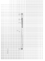
- FIG. 2 is a full view illustrating an example of the rack shaft 1 of a rack and pinion steering apparatus according to the present invention.
- the rack shaft 1 is rod-shaped having a circular cross section and the end portions thereof form connecting portions 25 to be connected with the steering tie rods 13.
- the outer surface in the proximity of a side end portion of the rack shaft 1 is provided with a flat face 26 having a proper width and a proper axial length corresponding to the movement stroke length.
- the rack teeth 3 are formed through a cutting process (gear cutting) of the flat face 26 using a metal cutting machine tool, such as a gear cutting machine or a broaching machine, capable of planing.
- the rack teeth 3 are formed as helical teeth inclined at a predetermined angle with respect to a direction perpendicular to the axial direction of the rack shaft 1.
- the specifications of the rack teeth 3 and the pinion teeth 4 are decided so that the pinion teeth 4 arranged on the circumference of the pinion shaft 2 fixed by a required stroke ratio of the rack shaft 1 are strong enough to withstand the manipulation force of the steering wheel 22 and the rotational force of the motor 5 to be loaded as described above and so that the tooth flank stress is reduced.
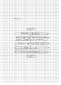
- FIG. 3 is a flow chart showing a method of manufacturing a rack shaft according to the present invention, e.g. a method of manufacturing the rack shaft 1 described above.
- a steel bar material (rod-shaped material) is refined so that the entire steel bar has a hardness high enough to withstand the load, which is necessary for the rack teeth 3 incorporated in the rack and pinion steering apparatus (S2).
- the refining is a process for obtaining characteristics superior in strength and toughness by quenching the steel bar to generate a martensitic structure and then tempering the steel bar at a relatively high temperature (400 to 650°C) to generate a fine mixed structure of cementite and ferrite.
- SCM440 Ceramic steel
- the hardness of the material is approximately HB (Brinell hardness) 300 to 360, for example.
- the steel bar undergoes drawing while passing through a dies having a bore of a predetermined circular form so that the steel bar has a uniform outer diameter of the rack shaft 1 (S4).
- the end portions of the steel bar undergo a process to form the connecting portions 25 (S6).
- the flat face 26 with a proper width is provided on the outer surface in the proximity of a side end portion of the steel bar, the rack teeth 3 are formed through a cutting process (gear cutting) of the flat face 26 using a gear cutting machine, a broaching machine or the like (S8), and then a finishing process such as surface polishing is performed (S10) to complete the rack shaft 1.
- a rack and pinion steering apparatus constructed as an electric power steering apparatus, which comprises a steering assist motor between the steering member and the pinion shaft so as to assist steering associated with the rotation of the pinion shaft by transmitting rotational force of the motor to the pinion shaft, namely, a column assist electric power steering apparatus
- the present invention may be applied to a rack and pinion steering apparatus constructed as an electric power steering apparatus of other types.
- the present invention may also be applied to a rack and pinion steering apparatus constructed as a manual steering apparatus, which steers the vehicle using only a steering torque applied to the steering wheel 22 by the driver, or to a rack and pinion steering apparatus constructed as a hydraulic power steering apparatus, which assists steering by applying to the rack shaft 1 force generated by a hydraulic cylinder provided in the middle of the rack housing 10.
Landscapes
- Engineering & Computer Science (AREA)
- Mechanical Engineering (AREA)
- Chemical & Material Sciences (AREA)
- General Engineering & Computer Science (AREA)
- Combustion & Propulsion (AREA)
- Transportation (AREA)
- Physics & Mathematics (AREA)
- Thermal Sciences (AREA)
- Crystallography & Structural Chemistry (AREA)
- Materials Engineering (AREA)
- Metallurgy (AREA)
- Organic Chemistry (AREA)
- Transmission Devices (AREA)
- Gears, Cams (AREA)
Abstract
Description
- The present invention relates to a rack and pinion steering apparatus, which is used extensively as a steering apparatus for vehicles, and a method of manufacturing a rack shaft of a rack and pinion steering apparatus.
- A rack and pinion steering apparatus comprises a pinion shaft, which is connected to a steering member such as a steering wheel and is provided with pinion teeth formed on the surface thereof, and a rack shaft, which extends from the right and left sides of a vehicle body and is provided with rack teeth juxtaposed on the outer surface of a middle portion thereof over a proper length. The rack and pinion steering apparatus is constructed to transform the rotation of the pinion shaft in accordance with the manipulation of the steering member by the driver into the axial movement of the rack shaft and to activate wheels for steering (right and left front wheels, in general) connected to the right and left ends of the rack shaft via respective steering tie rods.
- In such a rack and pinion steering apparatus, the pinion teeth on the pinion shaft and the rack teeth on the rack shaft are generally formed through a cutting process using a metal cutting machine tool such as a gear cutting machine or a broaching machine in order to obtain high mesh accuracy, and the tooth flank often undergoes a heat treatment in order to increase the surface hardness and the durability (see, for example, Japanese Patent Application Laid Open No. H06-264992 and Japanese Patent Application Publication No. H08-25462).
- In manufacturing of the rack shaft of the rack and pinion steering apparatus mentioned above, the rack shaft conventionally undergoes a gear cutting and then a heat treatment such as the induction quenching and tempering for the purpose of surface hardening. In the heat treatment, there is a problem that a straightening process for eliminating distortion, which may occur at the tooth flank or the shaft portions, becomes a major obstacle to the manufacturing processes. Moreover, there is another problem that the quenching may cause defects such as a quench crack.
- The present invention has been made with the aim of solving the above problems, and it is an object of the first invention to provide a rack and pinion steering apparatus which does not need quenching of the rack shaft after gear cutting of the rack shaft in manufacturing processes. The object of the second invention is to provide a method of manufacturing a rack shaft which does not need quenching after gear cutting.
- A rack and pinion steering apparatus according to the present invention, which comprises a pinion shaft and a rack shaft meshing with the pinion shaft, is characterized in that the rack shaft has a uniform hardness.
- A method of manufacturing a rack shaft of a rack and pinion steering apparatus according to the present invention is characterized by comprising steps of: refining an entire rod-shaped material to have hardness necessary for meshing with a pinion shaft; then drawing the rod-shaped material to uniform the outer diameter; forming end portions of the rod-shaped material into a predetermined shape; and then gear-cutting the rod-shaped material to finish the rack shaft.
- A method of manufacturing a rack shaft of a rack and pinion steering apparatus according to the present invention is characterized by comprising steps of: quenching a rod-shaped material formed of CrMo steel to generate a martensitic structure; tempering the rod-shaped material at a temperature of 400 to 650°C to generate a fine mixed structure of cementite and ferrite and to refine the rod-shaped material to have a Brinell hardness of approximately 300 to 360; drawing the rod-shaped material so as to be a round bar having a substantially uniform outer diameter; forming end portions of the rod-shaped material into a predetermined shape; and gear-cutting the rod-shaped material to finish the rack shaft.
- With the present invention, a rack and pinion steering apparatus which does not need quenching of the rack shaft after gear cutting of the rack shaft in manufacturing processes can be realized. Moreover, wear in a boundary portion of the pinion tooth flank to be contacted with the rack teeth, for example, can be reduced drastically (the rack tooth flank does not hit the pinion tooth flank and the rack follows the pinion) and the performance of the pinion, which is conventionally unfavorable in strength and durability, can be enhanced. Moreover, the incidence of a crack or a chip in the rack teeth can be reduced drastically. Moreover, a drastic reduction in cost can be realized since processes such as quenching and tempering as well as straightening after gear cutting of the rack shaft can be eliminated. Moreover, the quality of the rack shaft is raised since the rack shaft does not have distortion due to a heat treatment after gear cutting which may cause defects such as a quench crack.
- With the method of manufacturing a rack shaft according to the present invention, a rack shaft which does not need quenching after gear cutting can be manufactured. Moreover, wear in a boundary portion of the pinion tooth flank to be contacted with the rack teeth, for example, can be reduced drastically (the rack tooth flank does not hit the pinion tooth flank and the rack follows the pinion) and the performance of the pinion, which is conventionally unfavorable in strength and durability, can be enhanced. Moreover, the incidence of a crack or a chip in the rack teeth can be reduced drastically. Moreover, a drastic reduction in cost can be realized since processes such as quenching and tempering as well as straightening after gear cutting of the rack shaft can be eliminated. Moreover, the quality of the rack shaft is raised since the rack shaft does not have distortion due to a heat treatment after gear cutting which may cause defects such as a quench crack.
- The above and further objects and features of the invention will more fully be apparent from the following detailed description with accompanying drawings.
-
- FIG. 1 is a schematic view illustrating the structure of an embodiment of a rack and pinion steering apparatus according to the present invention;
- FIG. 2 is a full view illustrating an example of a rack shaft of a rack and pinion steering apparatus according to the present invention; and
- FIG. 3 is a flow chart showing a method of manufacturing a rack shaft according to the present invention.
-
- The following description will explain the present invention with reference to the drawings illustrating an embodiment thereof. FIG. 1 is a schematic view illustrating the structure of an embodiment of a rack and pinion steering apparatus according to the present invention. This rack and pinion steering apparatus comprises, a
rack shaft 1 supported so as to be freely movable in the axial direction extends from the right and left sides of a vehicle body, which is not illustrated in the figure, within acylindrical rack housing 10. The ends of therack shaft 1, which project from the both sides of therack housing 10, are connected to steeringknuckle arms front wheels steering tie rods - A
pinion housing 20 is arranged to extend in the proximity of a side end portion of therack housing 10 with the axis thereof crossing therack housing 10, and apinion shaft 2 is supported in thepinion housing 20 so as to be freely rotatable on the axis thereof. A part of thepinion shaft 2 projects upward from thepinion housing 20 in a proper length, and the projecting end is connected to a steering wheel 22, which is a steering member, via acolumn shaft 21. - The lower half of the
pinion shaft 2, which extends within thepinion housing 20, has a larger diameter over a proper length, andpinion teeth 4 are formed on the outer surface of this portion having a larger diameter. Meanwhile,rack teeth 3 are formed on the outer surface of arack shaft 1, which is supported in therack housing 10, in a proper length including a portion opposing thepinion shaft 2, and arack tooth 3 meshes with thepinion tooth 4 formed on the surface of thepinion shaft 2. - With the above structure, when the driver turns the steering wheel 22 to steer the vehicle, the
pinion shaft 2 connected to the steering wheel 22 via thecolumn shaft 21 rotates, and this rotation is transformed into an axial movement of therack shaft 1 at the meshing portion of apinion tooth 4 and arack tooth 3 so that therack shaft 1 moves right or left. - The movement of the
rack shaft 1 caused in such a manner is transmitted to the right and leftsteering knuckle arms steering tie rods rack shaft 1, and a push or pull of thesteering knuckle arms front wheels - It should be noted that the rack and pinion steering apparatus illustrated in FIG. 1 is constructed as an electric power steering apparatus comprising a
motor 5 for assisting such steering. Thesteering assist motor 5 is mounted on the outer surface in the proximity of the lower end portion of acylindrical column housing 23 for supporting thecolumn shaft 21, so as to cross thecolumn shaft 21 provided therein at an approximately right angle. The rotation of themotor 5 is transmitted to thecolumn shaft 21 via a worm gear reduction unit, which is not illustrated in the figure, constructed within thecolumn housing 23. In thecolumn housing 23, atorque detecting apparatus 24 for detecting a running torque (steering torque) applied to thecolumn shaft 21 is constructed above a mounting portion of themotor 5. A steering torque detected by thetorque detecting apparatus 24 is used for controlling the drive of thesteering assist motor 5. - With the above structure, when the driver turns the steering wheel 22, the
torque detecting apparatus 24 detects a steering torque applied to thecolumn shaft 21 associated with the turn of the steering wheel 22. Rotational force of thesteering assist motor 5, which is driven in a controlled manner based on the detected torque, is applied to thecolumn shaft 21 and then transmitted from thecolumn shaft 21 to thepinion shaft 2, and axial movement force is applied to therack shaft 1, so that the movement assists the steering described above. - FIG. 2 is a full view illustrating an example of the
rack shaft 1 of a rack and pinion steering apparatus according to the present invention. Therack shaft 1 is rod-shaped having a circular cross section and the end portions thereofform connecting portions 25 to be connected with thesteering tie rods 13. The outer surface in the proximity of a side end portion of therack shaft 1 is provided with aflat face 26 having a proper width and a proper axial length corresponding to the movement stroke length. Therack teeth 3 are formed through a cutting process (gear cutting) of theflat face 26 using a metal cutting machine tool, such as a gear cutting machine or a broaching machine, capable of planing. Therack teeth 3 are formed as helical teeth inclined at a predetermined angle with respect to a direction perpendicular to the axial direction of therack shaft 1. - The specifications of the
rack teeth 3 and thepinion teeth 4 are decided so that thepinion teeth 4 arranged on the circumference of thepinion shaft 2 fixed by a required stroke ratio of therack shaft 1 are strong enough to withstand the manipulation force of the steering wheel 22 and the rotational force of themotor 5 to be loaded as described above and so that the tooth flank stress is reduced. - FIG. 3 is a flow chart showing a method of manufacturing a rack shaft according to the present invention, e.g. a method of manufacturing the
rack shaft 1 described above. In manufacturing of therack shaft 1, first, a steel bar material (rod-shaped material) is refined so that the entire steel bar has a hardness high enough to withstand the load, which is necessary for therack teeth 3 incorporated in the rack and pinion steering apparatus (S2). The refining is a process for obtaining characteristics superior in strength and toughness by quenching the steel bar to generate a martensitic structure and then tempering the steel bar at a relatively high temperature (400 to 650°C) to generate a fine mixed structure of cementite and ferrite. Used as a material to be refined (material) is SCM440 (CrMo steel), for example. The hardness of the material is approximately HB (Brinell hardness) 300 to 360, for example. - Next, the steel bar undergoes drawing while passing through a dies having a bore of a predetermined circular form so that the steel bar has a uniform outer diameter of the rack shaft 1 (S4). Then, the end portions of the steel bar undergo a process to form the connecting portions 25 (S6). Then, the
flat face 26 with a proper width is provided on the outer surface in the proximity of a side end portion of the steel bar, therack teeth 3 are formed through a cutting process (gear cutting) of theflat face 26 using a gear cutting machine, a broaching machine or the like (S8), and then a finishing process such as surface polishing is performed (S10) to complete therack shaft 1. - It should be noted that, though explained in the above embodiment is a rack and pinion steering apparatus constructed as an electric power steering apparatus, which comprises a steering assist motor between the steering member and the pinion shaft so as to assist steering associated with the rotation of the pinion shaft by transmitting rotational force of the motor to the pinion shaft, namely, a column assist electric power steering apparatus, the present invention may be applied to a rack and pinion steering apparatus constructed as an electric power steering apparatus of other types. Moreover, it is needless to say that the present invention may also be applied to a rack and pinion steering apparatus constructed as a manual steering apparatus, which steers the vehicle using only a steering torque applied to the steering wheel 22 by the driver, or to a rack and pinion steering apparatus constructed as a hydraulic power steering apparatus, which assists steering by applying to the
rack shaft 1 force generated by a hydraulic cylinder provided in the middle of therack housing 10.
Claims (3)
- A rack and pinion steering apparatus comprising:characterized in that the rack shaft (1) has a substantially uniform hardness.a pinion shaft (2); anda rack shaft (1) meshing with the pinion shaft (2),
- A method of manufacturing a rack shaft (1) of a rack and pinion steering apparatus, characterized by comprising steps of:refining an entire rod-shaped material to have hardness necessary for meshing with a pinion shaft (2):drawing the rod-shaped material so as to be a round bar having a substantially uniform outer diameter;forming end portions of the rod-shaped material into a predetermined shape; andgear-cutting the rod-shaped material to finish the rack shaft.
- A method of manufacturing a rack shaft (1) of a rack and pinion steering apparatus, characterized by comprising steps of:quenching a rod-shaped material formed of CrMo steel to generate a martensitic structure;tempering the rod-shaped material at a temperature of 400 to 650°C to generate a fine mixed structure of cementite and ferrite and to refine the rod-shaped material to have a Brinell hardness of approximately 300 to 360;drawing the rod-shaped material so as to be a round bar having a substantially uniform outer diameter;forming end portions of the rod-shaped material into a predetermined shape; andgear-cutting the rod-shaped material to finish the rack shaft (1).
Applications Claiming Priority (2)
| Application Number | Priority Date | Filing Date | Title |
|---|---|---|---|
| JP2003397690A JP2005153791A (en) | 2003-11-27 | 2003-11-27 | Rack and pinion type steering apparatus and method for manufacturing rack rod |
| JP2003397690 | 2003-11-27 |
Publications (2)
| Publication Number | Publication Date |
|---|---|
| EP1547904A1 true EP1547904A1 (en) | 2005-06-29 |
| EP1547904B1 EP1547904B1 (en) | 2008-07-23 |
Family
ID=34544865
Family Applications (1)
| Application Number | Title | Priority Date | Filing Date |
|---|---|---|---|
| EP04106096A Expired - Lifetime EP1547904B1 (en) | 2003-11-27 | 2004-11-25 | Method of manufacturing rack shaft |
Country Status (5)
| Country | Link |
|---|---|
| US (1) | US7631428B2 (en) |
| EP (1) | EP1547904B1 (en) |
| JP (1) | JP2005153791A (en) |
| KR (1) | KR20050051555A (en) |
| DE (1) | DE602004015235D1 (en) |
Cited By (1)
| Publication number | Priority date | Publication date | Assignee | Title |
|---|---|---|---|---|
| CN109128708A (en) * | 2018-09-29 | 2019-01-04 | 徐州徐工履带底盘有限公司 | A kind of thrust wheel wheel shaft processing method |
Families Citing this family (7)
| Publication number | Priority date | Publication date | Assignee | Title |
|---|---|---|---|---|
| KR100718781B1 (en) | 2005-06-15 | 2007-05-16 | 매그나칩 반도체 유한회사 | CMOS Image Sensor with Compact Pixel Layout |
| JP5240058B2 (en) * | 2009-05-13 | 2013-07-17 | 日本精工株式会社 | Manufacturing method of rack and pinion type electric power steering apparatus |
| JP5402843B2 (en) * | 2010-06-16 | 2014-01-29 | 日本精工株式会社 | Rack shaft, manufacturing method thereof, and rack and pinion type steering gear unit |
| JP5843023B2 (en) * | 2013-06-12 | 2016-01-13 | 日本精工株式会社 | Rack and pinion type steering gear unit |
| CN104708290B (en) * | 2015-03-17 | 2017-07-07 | 上海格尔汽车科技发展有限公司 | A kind of processing method of electric steering gear tooth bar |
| KR101676244B1 (en) * | 2015-04-14 | 2016-11-29 | 현대자동차주식회사 | Carbon steel compositions reduced thermal strain for steering rack bar and method for manufacturing the same |
| FR3103721B1 (en) * | 2019-11-28 | 2022-09-09 | Jtekt Europe Sas | Method for manufacturing a rack comprising variable-pitch toothing implementing a roughing step followed by a finishing step |
Citations (6)
| Publication number | Priority date | Publication date | Assignee | Title |
|---|---|---|---|---|
| GB995965A (en) * | 1964-04-21 | 1965-06-23 | Zweirad Union A G | Rack and pinion steering gear |
| US4646554A (en) * | 1982-01-25 | 1987-03-03 | Zahnradfabrik Friedrichshafen Ag. | Process for the manufacture of a rack |
| JPH06264992A (en) * | 1993-03-14 | 1994-09-20 | Yamada Seisakusho Kk | Steering rack shaft |
| EP1215102A2 (en) * | 2000-12-18 | 2002-06-19 | NSK Ltd., | Hollow rack shaft and manufacturing method thereof |
| GB2372952A (en) * | 2001-03-09 | 2002-09-11 | Morphious Ltd | Manufacturing gear racks with helicoidal teeth |
| JP2004237316A (en) * | 2003-02-06 | 2004-08-26 | High Frequency Heattreat Co Ltd | Manufacturing method of hollow steering rack shaft |
Family Cites Families (12)
| Publication number | Priority date | Publication date | Assignee | Title |
|---|---|---|---|---|
| US1998108A (en) * | 1931-02-18 | 1935-04-16 | Borg Warner | Torque transmitting member and method for producing the same |
| FR2187919B1 (en) * | 1972-06-15 | 1974-10-25 | Bonvarite | |
| US4098624A (en) * | 1976-12-28 | 1978-07-04 | Upton Industries, Inc. | Process for increasing the versatility of isothermal transformation |
| JPH0825462B2 (en) | 1989-10-09 | 1996-03-13 | 日産自動車株式会社 | Steering device |
| JPH075970B2 (en) * | 1989-12-18 | 1995-01-25 | 住友金属工業株式会社 | High carbon steel sheet manufacturing method |
| US5069080A (en) * | 1990-03-08 | 1991-12-03 | Simon Joseph A | Elongated, lightweight rack |
| US5473960A (en) * | 1993-03-14 | 1995-12-12 | Kabushiki Kaisha Yamada Seisakusho | Steering rack shaft and method of manufacturing the same |
| DE4331291C1 (en) * | 1993-09-15 | 1994-12-15 | Lemfoerder Metallwaren Ag | Articulated connection for a rack-and-pinion steering system for motor vehicles |
| US6588293B2 (en) * | 2000-04-14 | 2003-07-08 | Nsk Ltd. | Hollow rack shaft |
| BR0003428A (en) * | 2000-07-28 | 2004-06-08 | Dana Ind S A | Spherical joint with pressure equalization system |
| US6508981B1 (en) * | 2001-05-24 | 2003-01-21 | Wescast Industries, Inc. | High temperature oxidation resistant ductile iron |
| JP3994763B2 (en) * | 2002-03-14 | 2007-10-24 | 株式会社ジェイテクト | Torsion bar manufacturing method and torsion bar |
-
2003
- 2003-11-27 JP JP2003397690A patent/JP2005153791A/en active Pending
-
2004
- 2004-11-24 KR KR1020040096779A patent/KR20050051555A/en not_active Withdrawn
- 2004-11-25 EP EP04106096A patent/EP1547904B1/en not_active Expired - Lifetime
- 2004-11-25 DE DE602004015235T patent/DE602004015235D1/en not_active Expired - Lifetime
- 2004-11-29 US US10/999,808 patent/US7631428B2/en active Active
Patent Citations (6)
| Publication number | Priority date | Publication date | Assignee | Title |
|---|---|---|---|---|
| GB995965A (en) * | 1964-04-21 | 1965-06-23 | Zweirad Union A G | Rack and pinion steering gear |
| US4646554A (en) * | 1982-01-25 | 1987-03-03 | Zahnradfabrik Friedrichshafen Ag. | Process for the manufacture of a rack |
| JPH06264992A (en) * | 1993-03-14 | 1994-09-20 | Yamada Seisakusho Kk | Steering rack shaft |
| EP1215102A2 (en) * | 2000-12-18 | 2002-06-19 | NSK Ltd., | Hollow rack shaft and manufacturing method thereof |
| GB2372952A (en) * | 2001-03-09 | 2002-09-11 | Morphious Ltd | Manufacturing gear racks with helicoidal teeth |
| JP2004237316A (en) * | 2003-02-06 | 2004-08-26 | High Frequency Heattreat Co Ltd | Manufacturing method of hollow steering rack shaft |
Non-Patent Citations (2)
| Title |
|---|
| PATENT ABSTRACTS OF JAPAN vol. 018, no. 677 (M - 1727) 20 December 1994 (1994-12-20) * |
| PATENT ABSTRACTS OF JAPAN vol. 2003, no. 12 5 December 2003 (2003-12-05) * |
Cited By (1)
| Publication number | Priority date | Publication date | Assignee | Title |
|---|---|---|---|---|
| CN109128708A (en) * | 2018-09-29 | 2019-01-04 | 徐州徐工履带底盘有限公司 | A kind of thrust wheel wheel shaft processing method |
Also Published As
| Publication number | Publication date |
|---|---|
| JP2005153791A (en) | 2005-06-16 |
| EP1547904B1 (en) | 2008-07-23 |
| DE602004015235D1 (en) | 2008-09-04 |
| KR20050051555A (en) | 2005-06-01 |
| US20050139026A1 (en) | 2005-06-30 |
| US7631428B2 (en) | 2009-12-15 |
Similar Documents
| Publication | Publication Date | Title |
|---|---|---|
| DE102012011509B4 (en) | Method of manufacturing a stepped bar and stepped bar | |
| CN109415083B (en) | Geared rack and method for producing a geared rack for a steering gear of a motor vehicle | |
| CN109415079B (en) | Rack and pinion and method for producing a rack and pinion for steering gears of motor vehicles | |
| EP1547904B1 (en) | Method of manufacturing rack shaft | |
| KR20100077393A (en) | Manufacturing method of the worm-shaft for mdps | |
| US20050172744A1 (en) | Reduction gear and method and apparatus for manufacturing the reduction gear concerned, and electric power steering system with the reduction gear concerned | |
| JP2011148403A (en) | Method for manufacturing rack-and-pinion type steering device | |
| US10926788B2 (en) | Method for producing a toothed rack for a motor vehicle | |
| US11781633B2 (en) | Rack bar and steering apparatus | |
| DE102012008628B4 (en) | Method for manufacturing a threaded drive rod | |
| CN109415082B (en) | Rack and method for producing a rack for a steering device of a motor vehicle | |
| JP2005299854A (en) | Pinion shaft | |
| CN113260552B (en) | Linear drive shaft for electric power steering device, and methods for manufacturing linear drive shaft and electric power steering device | |
| EP1666770A1 (en) | Speed reducer, method and appratus for manufacturing the speed reducer, and electric power steering device with the speed reducer | |
| EP3628567A1 (en) | Steering system | |
| JP5471492B2 (en) | Manufacturing method of rack and pinion type steering device | |
| JP2012110913A (en) | Worm wheel, manufacturing method thereof, and electric power steering device | |
| JP5471493B2 (en) | Manufacturing method of rack and pinion type steering device | |
| KR102940521B1 (en) | Manufacture method of Worm shaft For MDPS | |
| KR20110125339A (en) | Rack bar and steering system with rack bar and method of manufacturing rack bar | |
| JP2014054906A (en) | Rack pinion type steering device | |
| JP2010018067A (en) | Rack and pinion type steering device | |
| JP2010018068A (en) | Rack and pinion type steering device | |
| KR20160134405A (en) | How to avoid using the same tube deformation and strain relief member unit of universal joints for steering systems |
Legal Events
| Date | Code | Title | Description |
|---|---|---|---|
| PUAI | Public reference made under article 153(3) epc to a published international application that has entered the european phase |
Free format text: ORIGINAL CODE: 0009012 |
|
| AK | Designated contracting states |
Kind code of ref document: A1 Designated state(s): AT BE BG CH CY CZ DE DK EE ES FI FR GB GR HU IE IS IT LI LU MC NL PL PT RO SE SI SK TR |
|
| AX | Request for extension of the european patent |
Extension state: AL HR LT LV MK YU |
|
| 17P | Request for examination filed |
Effective date: 20051228 |
|
| AKX | Designation fees paid |
Designated state(s): DE FR GB |
|
| RAP1 | Party data changed (applicant data changed or rights of an application transferred) |
Owner name: JTEKT CORPORATION |
|
| 17Q | First examination report despatched |
Effective date: 20060313 |
|
| 17Q | First examination report despatched |
Effective date: 20060313 |
|
| GRAP | Despatch of communication of intention to grant a patent |
Free format text: ORIGINAL CODE: EPIDOSNIGR1 |
|
| RTI1 | Title (correction) |
Free format text: METHOD OF MANUFACTURING RACK SHAFT |
|
| GRAS | Grant fee paid |
Free format text: ORIGINAL CODE: EPIDOSNIGR3 |
|
| GRAA | (expected) grant |
Free format text: ORIGINAL CODE: 0009210 |
|
| AK | Designated contracting states |
Kind code of ref document: B1 Designated state(s): DE FR GB |
|
| REG | Reference to a national code |
Ref country code: GB Ref legal event code: FG4D |
|
| REF | Corresponds to: |
Ref document number: 602004015235 Country of ref document: DE Date of ref document: 20080904 Kind code of ref document: P |
|
| PLBE | No opposition filed within time limit |
Free format text: ORIGINAL CODE: 0009261 |
|
| STAA | Information on the status of an ep patent application or granted ep patent |
Free format text: STATUS: NO OPPOSITION FILED WITHIN TIME LIMIT |
|
| 26N | No opposition filed |
Effective date: 20090424 |
|
| PGFP | Annual fee paid to national office [announced via postgrant information from national office to epo] |
Ref country code: GB Payment date: 20101124 Year of fee payment: 7 |
|
| GBPC | Gb: european patent ceased through non-payment of renewal fee |
Effective date: 20121125 |
|
| PG25 | Lapsed in a contracting state [announced via postgrant information from national office to epo] |
Ref country code: GB Free format text: LAPSE BECAUSE OF NON-PAYMENT OF DUE FEES Effective date: 20121125 |
|
| REG | Reference to a national code |
Ref country code: FR Ref legal event code: PLFP Year of fee payment: 12 |
|
| REG | Reference to a national code |
Ref country code: FR Ref legal event code: PLFP Year of fee payment: 13 |
|
| REG | Reference to a national code |
Ref country code: FR Ref legal event code: PLFP Year of fee payment: 14 |
|
| REG | Reference to a national code |
Ref country code: FR Ref legal event code: PLFP Year of fee payment: 15 |
|
| PGFP | Annual fee paid to national office [announced via postgrant information from national office to epo] |
Ref country code: FR Payment date: 20221010 Year of fee payment: 19 |
|
| PGFP | Annual fee paid to national office [announced via postgrant information from national office to epo] |
Ref country code: DE Payment date: 20220930 Year of fee payment: 19 |
|
| REG | Reference to a national code |
Ref country code: DE Ref legal event code: R119 Ref document number: 602004015235 Country of ref document: DE |
|
| PG25 | Lapsed in a contracting state [announced via postgrant information from national office to epo] |
Ref country code: DE Free format text: LAPSE BECAUSE OF NON-PAYMENT OF DUE FEES Effective date: 20240601 |
|
| PG25 | Lapsed in a contracting state [announced via postgrant information from national office to epo] |
Ref country code: FR Free format text: LAPSE BECAUSE OF NON-PAYMENT OF DUE FEES Effective date: 20231130 |
|
| PG25 | Lapsed in a contracting state [announced via postgrant information from national office to epo] |
Ref country code: FR Free format text: LAPSE BECAUSE OF NON-PAYMENT OF DUE FEES Effective date: 20231130 Ref country code: DE Free format text: LAPSE BECAUSE OF NON-PAYMENT OF DUE FEES Effective date: 20240601 |