EP1547820A1 - Pneumatic tire - Google Patents
Pneumatic tire Download PDFInfo
- Publication number
- EP1547820A1 EP1547820A1 EP03771428A EP03771428A EP1547820A1 EP 1547820 A1 EP1547820 A1 EP 1547820A1 EP 03771428 A EP03771428 A EP 03771428A EP 03771428 A EP03771428 A EP 03771428A EP 1547820 A1 EP1547820 A1 EP 1547820A1
- Authority
- EP
- European Patent Office
- Prior art keywords
- block
- tire
- circumferential direction
- height
- pneumatic tire
- Prior art date
- Legal status (The legal status is an assumption and is not a legal conclusion. Google has not performed a legal analysis and makes no representation as to the accuracy of the status listed.)
- Granted
Links
Images


Classifications
-
- B—PERFORMING OPERATIONS; TRANSPORTING
- B60—VEHICLES IN GENERAL
- B60C—VEHICLE TYRES; TYRE INFLATION; TYRE CHANGING; CONNECTING VALVES TO INFLATABLE ELASTIC BODIES IN GENERAL; DEVICES OR ARRANGEMENTS RELATED TO TYRES
- B60C11/00—Tyre tread bands; Tread patterns; Anti-skid inserts
- B60C11/03—Tread patterns
- B60C11/13—Tread patterns characterised by the groove cross-section, e.g. for buttressing or preventing stone-trapping
- B60C11/1376—Three dimensional block surfaces departing from the enveloping tread contour
- B60C11/1392—Three dimensional block surfaces departing from the enveloping tread contour with chamfered block edges
-
- B—PERFORMING OPERATIONS; TRANSPORTING
- B60—VEHICLES IN GENERAL
- B60C—VEHICLE TYRES; TYRE INFLATION; TYRE CHANGING; CONNECTING VALVES TO INFLATABLE ELASTIC BODIES IN GENERAL; DEVICES OR ARRANGEMENTS RELATED TO TYRES
- B60C11/00—Tyre tread bands; Tread patterns; Anti-skid inserts
- B60C11/03—Tread patterns
- B60C11/11—Tread patterns in which the raised area of the pattern consists only of isolated elements, e.g. blocks
-
- B—PERFORMING OPERATIONS; TRANSPORTING
- B60—VEHICLES IN GENERAL
- B60C—VEHICLE TYRES; TYRE INFLATION; TYRE CHANGING; CONNECTING VALVES TO INFLATABLE ELASTIC BODIES IN GENERAL; DEVICES OR ARRANGEMENTS RELATED TO TYRES
- B60C11/00—Tyre tread bands; Tread patterns; Anti-skid inserts
- B60C11/03—Tread patterns
- B60C11/13—Tread patterns characterised by the groove cross-section, e.g. for buttressing or preventing stone-trapping
- B60C11/1376—Three dimensional block surfaces departing from the enveloping tread contour
Definitions
- the present invention relates to a pneumatic tire and, more particularly, to a pneumatic tire having a block pattern and being capable of exhibiting an excellent effect of suppressing a heel-and-toe wear.
- an object of the present invention is to provide a pneumatic tire, in which a heel-and-toe wear can be securely suppressed even if the height of each block is high.
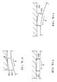
- a sliding direction in the vicinity of a trailing edge with respect to a road surface is a direction opposite to a rotational direction of a tire in the low block.
- the sliding direction in the vicinity of the trailing edge with respect to the road surface is identical to the rotational direction of the tire in a high block. Therefore, it was found that the sliding directions at the trailing edges are different from each other between the low block and the high block.
- a heel-and-toe wear is generated due to the slide in the vicinity of the trailing edge in the direction opposite to the rotational direction of the tire.
- This mechanism of generation of the heel-and-toe wear in the low block 100 has been conventionally known.
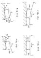
- a high block 200 is largely bent and deformed in a circumferential direction at the time of contacting in comparison with the low block (see Fig. 10A), as shown in Fig. 11A.
- the high block 200 is compressed by a load from above in the vicinity of the central portion within the ground contacting plane, and therefore, the high block 200 is also deformed into a barrel shape as a whole in the same manner as the low block, as shown in Fig. 11B.
- the influence of the bending deformation in the circumferential direction also remains.
- the present inventors have keen examined the shape of the block so as to suppress a local bending deformation in the vicinity of the trailing edge of the block, and thus, have reached the present invention.
- the invention according to claim 1 is a pneumatic tire including a tread provided with a plurality of blocks divided by a plurality of circumferential main grooves extending in a tire circumferential direction and lateral grooves intersecting the circumferential main grooves, the pneumatic tire being characterized in that: a block height of each block is gradually reduced from a central portion of the block in the circumferential direction toward a leading edge and a trailing edge, and at least a profile line of a tread surface has a recess dented inward in a tire radial direction beyond a virtual line connecting a first position, at which the block height begins to be gradually reduced, and a block edge of the block in the tire circumferential direction between the first position and the block edge, as viewed in a cross section perpendicular to a rotational axis of the tire.
- a recess dented inward in a tire radial direction beyond a virtual line connecting a first position, at which the block height begins to be gradually reduced, and a block edge of the block in the tire circumferential direction between the first position and the block edge, is provided. Consequently, first, as the block height is low at the leading edge, and the rubber volume in the vicinity of the leading edge is reduced in comparison with a conventional block of which tread surface is formed by only arcs, which have a center of curvature inside of the tire, the ground contacting timing at the time of contact is delayed. As a result, bending deformation of the entire block is suppressed.
- the bending deformation in the vicinity of the trailing edge can be suppressed by the two effects, which are the bending deformation suppressing effect of the entire block at the time of ground contacting, and the local bending deformation suppressing effect right before leaving, as described above.
- the invention according to claim 2 is a pneumatic tire including a tread provided with a plurality of blocks divided by a plurality of circumferential main grooves extending in a tire circumferential direction and lateral grooves intersecting the circumferential main grooves, the pneumatic tire being characterized in that: a block height of each block is gradually reduced from a central portion of the block in the circumferential direction toward a leading edge and a trailing edge, and at least a profile line of a tread surface includes a first arcuate portion, which is formed at the central portion of the block in the circumferential direction and which has a center of curvature inside of the tire, and second arcuate portions, which are formed at both sides of the first arcuate portion in the tire circumferential direction and which have a center of curvature outside of the tire, as viewed in a cross section perpendicular to a rotational axis of a tire.
- the second arcuate portions which each have the center of curvature outside of the tire, are formed at both sides of the first arcuate portion in the tire circumferential direction at the tread surface of the block. Consequently, first, as the block height is low at the leading edge, and the rubber volume in the vicinity of the leading edge is reduced in comparison with a conventional block of which tread surface is formed by only arcs, which have a center of curvature inside of the tire, the ground contacting timing at the time of contact is delayed. As a result, bending deformation of the entire block is suppressed.
- the bending deformation in the vicinity of the trailing edge can be suppressed by the two effects, which are the bending deformation suppressing effect of the entire block at the time of ground contacting, and the local bending deformation suppressing effect right before leaving, as described above.
- the invention according to claim 3 is a pneumatic tire according to claim 1 or claim 2, characterized in that the following relationship is satisfied: 0.04 ⁇ H/R ⁇ 0.06, wherein H designates a maximum height of the block, and R designates a tire radius measured at the central portion of the tread surface of the block.
- the effect according to the present invention can be sufficiently exhibited by setting the maximum height H of the block to satisfy the relationship 0.04 ⁇ H/R ⁇ 0.06.
- the maximum height H/R of the block is less than 0.04, the effect according to the present invention cannot be sufficiently exhibited since the block is not very high.
- the central portion of the tread surface of the block signifies a point at which is a center in a tire axial direction and a center in the tire circumferential direction of the tread surface of the block.
- the pneumatic tire according to claim 3 is structured as described above, and thus has an excellent effect that the effect according to the present invention can be sufficiently exhibited.
- the invention according to claim 4 is a pneumatic tire according to any one of claims 1 to 3, characterized in that the following relationship is satisfied: 0.02H ⁇ d ⁇ 0.07H, wherein H designates a maximum height of the block; and d is equal to H-he and designates an amount of depth, where he denotes a block height at the leading edge and the trailing edge.
- the pneumatic tire according to claim 4 is structured as described above, and thus has an excellent effect that the heel-and-toe wear suppressing effect according to the present invention can be securely exhibited without any degradation of other performances.
- the invention according to claim 5 is a pneumatic tire according to any one of claims 1 to 4, characterized in that a low region satisfying the relationship of an average block height hL ⁇ he + (H-he) ⁇ 0.2, where H designates a maximum height of the block and he designates a block height at the leading edge and the trailing edge, is formed from the leading edge for a length of at least H/5 toward the central portion of the block in the circumferential direction and from the trailing edge for a length of at least H/5 toward the central portion of the block in the circumferential direction.
- the low region satisfying the average block height hL ⁇ he + (H-he) ⁇ 0.2 is not formed from the leading edge for a length of at least H/5 toward the central portion of the block in the circumferential direction and from the trailing edge for a length of at least H/5 toward the central portion of the block in the circumferential direction, the bending deformation of the block at the time of contact cannot be suppressed, or the local bending deformation in the vicinity of the trailing edge cannot be suppressed.
- the pneumatic tire according to claim 5 is structured as described above, and thus has an excellent effect that the heel-and-toe wear suppressing effect in the high block can be securely exhibited.
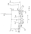
- a pneumatic tire 10 is a tire for a truck and a bus having a tire size of 295/75R22.5.
- a tread 12 thereof there are provided a plurality of rectangular blocks 18 divided by a plurality of circumferential main grooves 14 and a plurality of lateral grooves 16, and form a so-called block pattern.
- the inside structure of the pneumatic tire 10 is the same as the structure of a general radial tire, and therefore, detail description thereof will be omitted.
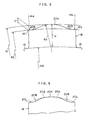
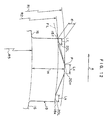
- a new block 18 when viewed in a cross section perpendicular to a tire rotational axis, the block 18 is gradually reduced in height from a central portion of a block in a circumferential direction toward a leading edge 18f and a trailing edge 18k.
- an arrow A indicates a tire rotational direction.
- a portion having a length Lc in the circumferential direction at the central portion of the block in the circumferential direction is a top portion 20H having a predetermined height (i.e., an arc formed by a curvature radius R1 which passes the central portion of the block in the circumferential direction and which has the tire rotational axis as a center of curvature).
- a portion having a length Lf in the circumferential direction from the leading edge 18f toward the central portion of the block in the circumferential direction and a portion having a length Lk in the circumferential direction from the trailing edge 18k toward the central portion of the block in the circumferential direction are bottom portions 20L, each having a certain height, (i.e., an arc having a curvature radius R2 which passes the leading edge 18f and the trailing edge 18k, and which has the tire rotational axis as a center of curvature).
- a maximum height of the block 18 is designated by H, which is measured from a groove bottom line connecting the respective groove bottoms of each lateral grooves 16 in the tire circumferential direction (i.e., an arc depicted by a chain double-dashed line indicating a circular arc having a radius R5 which has the tire rotational axis as a center of curvature).
- the block 18 is a relatively high block, which satisfies the following relationship: 0.04 ⁇ H/R ⁇ 0.06.
- first arcuate portions 20A which have a radius R3 having a center of curvature inside of the tire, are provided at both sides of the top portion 20H.
- second arcuate portions 20B which have a radius R4 having a center of curvature outside of the tire, are provided.
- the top portion 20H, the first arcuate portions 20A, the second arcuate portions 20B and the bottom portions 20L are smoothly connected to one another.
- the present invention is not limited to the above-described structure.
- the top portion 20H may extend relatively long in the tire circumferential direction and the bottom portions 20L, which extend in the tire circumferential direction with a predetermined height, may not be provided.
- the height of the central portion of the block is constant in the embodiment shown in Fig. 3.
- the height may be gradually reduced toward both sides in the circumferential direction as long as the top portion 20H is approximate to the arc having the curvature radius R1.
- one first arcuate portion 20A may be provided at the central portion of the block 18, and two second arcuate portions 20B and two bottom portions 20L may be provided at both sides of the first arcuate portion 20A (i.e., there is no top portion 20H extending in the circumferential direction in a predetermined height).
- the height is constant in the vicinity of both ends of the block in the embodiment shown in Fig. 4, the height may be gradually reduced toward both ends in the circumferential direction as long as the bottom portion 20L is approximate to the arc having the curvature radius R2.
- one first arcuate portion 20A may be provided at the central portion of the block 18, and only two second arcuate portions 20B may be provided at both sides of the first arcuate portion 20A.
- a straight portion may be provided at a portion of the tread surface of the block 18.
- arcuate portions having a plurality of different curvature radii may be provided at a portion of the tread surface of the block 18.
- an amount of depth d satisfies the following relationship: 0.02H ⁇ d ⁇ 0.07H, where d designates the amount of depth obtained by subtracting a block height he at the leading edge 18f and the trailing edge 18k from the maximum height H of the block 18.
- a low region satisfying an average block height hL ⁇ he + (H-he) ⁇ 0.2 is formed from the leading edge 18f for a length of at least H/5 toward the central portion of the block in the circumferential direction and from the trailing edge 18k for a length of at least H/5 toward the central portion of the block in the circumferential direction.
- the length L in the tire circumferential direction is set to 50 mm
- the width W in the tire axial direction is set to 32 mm
- the height H is set to 25 mm
- the amount of depth d is set to 1 mm
- the length Lc of the top portion 20H is set to 10 mm
- the curvature radius R3 of the first arcuate portion 20A is set to 112.6 mm
- the curvature radius R4 of the second arcuate portion 20B is set to 112.6 mm
- the lengths Lk and Lf of the low portions 20L are set to 5 mm.
- the radius of the pneumatic tire 10 of the present embodiment ranges from 490 mm (at a shoulder portion) to 503 mm (at a tire equatorial surface CL).
- the second arcuate portion 20B having the center of curvature outside of the tire is formed at the leading edge 18f side of the first arcuate portion 20A having the curvature center inside of the tire at the tread surface of the block 18. Consequently, the block height is low at the leading edge 18f and a rubber volume in the vicinity of the leading edge 18f is reduced in comparison with the conventional block (as indicated by a chain double-dashed line in Fig. 6), of which the tread surface is formed of only an arc having the center of curvature inside of the tire, so that a ground contacting timing at the time of contact is delayed. As a result, bending deformation of the entire block is suppressed.
- the rubber volume in the vicinity of the trailing edge 18k is reduced in comparison with the conventional block, of which the tread surface is formed of only the arc having the center of curvature inside of the tire. Therefore, bending deformation in a direction opposite to the tire rotational direction, which is generated in the vicinity of the trailing edge 18k right before leaving, can be suppressed.
- the pneumatic tire 10 of the present embodiment can suppress the bending deformation in the vicinity of the trailing edge 18k by two effects, which are the bending deformation suppressing effect of the entire block 18 at the time of contacting the ground and the local bending deformation suppressing effect right before leaving, and therefore, can reduce a slide in the direction opposite to the tire rotational direction in the vicinity of the trailing edge 18k at the time of leaving and suppress a heel-and-toe wear from being generated in the case of the relatively high block 18.
- the maximum height H of the block 18 is less than 20 mm, the effect according to the present invention cannot be sufficiently exhibited.
- the maximum height H of the block 18 exceeds 30 mm, the block 18 will be too high and the bending deformation of the block 18 cannot be sufficiently suppressed.
- the amount of depth d of the block 18 is less than 0.5 mm, a difference in height is too small to achieve the heel-and-toe wear suppressing effect.
- the amount of depth d of the block 18 exceeds 3.0 mm, there may possibly arise a problem that the distribution of a ground contacting pressure becomes non-uniform or that both ends in the circumferential direction of the block 18 may not contact the ground.
- the low region satisfying the average block height hL ⁇ he + (H-he) ⁇ 0.2 is not formed from the leading edge 18f for a length of at least 5 mm toward the central portion of the block in the circumferential direction and is not formed from the trailing edge 18k for a length of at least 5 mm toward the central portion of the block in the circumferential direction, there is a possibility that the bending deformation of the block 18 at the time of contact cannot be suppressed, or the local bending deformation in the vicinity of the trailing edge 18k cannot be suppressed.
- the first arcuate portion 20A and the second arcuate portion 20B which have an relatively great curvature radius, are formed between the top portion 20H and the low portion 20L.
- the respective curvature radii of the first arcuate portion 20A and the second arcuate portion 20B are not limited to those curvature radii in the above-described embodiment, and may be much smaller, or may be 1 mm or less. In some cases, the first arcuate portion 20A and the second arcuate portion 20B may not be provided.
- reference character FL denotes a virtual line (a straight line), which connects a first position P, at which the height of the block begins to be gradually reduced, and the leading edge 18f of the block 18 (i.e., a block edge of the block in the tire circumferential direction).
- the tread surface of the block 18 is dented more than the virtual line FL between the first position P and the leading edge 18f (the opposite side also has the same shape).
- a pneumatic tire of conventional example 1 a pneumatic tire of comparative example 1 and a pneumatic tire of example 1, to which the present invention is applied, were prototyped, and were subjected to an wearing test in an actual vehicle.
- the size of each of the pneumatic tires was 295/75R22.5, and an inner pressure was set to 650 kPa.
- the pneumatic tire of Example 1 was the pneumatic tire in the above-described embodiment.
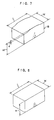
- a block of the pneumatic tire of the conventional example 1 was constantly 50 mm in length L in a circumferential direction, 32 mm in width W in a tire axial direction and 25 mm in height H, as shown in Fig. 8.
- a block of the pneumatic tire of the comparative example 1 was 50 mm in length L in a circumferential direction, 32 mm in width W in a tire axial direction and 25 mm in maximum height H, and a tread surface was formed in an arc having a single curvature radius (R) having a center of curvature inside of the tire (as viewed in a cross section perpendicular to the tire rotational axis).
- An amount of depth d was set to 1 mm.
- each of the tires was mounted to a drive wheel of the actual vehicle of 2D4, and the vehicle was made to travel by 20,000 km. After traveling, a volume of rubber of a shoulder block (i.e., an outermost block in a tire width direction) dissipated due to the heel-and-toe wear was measured.
- a volume of rubber of a shoulder block i.e., an outermost block in a tire width direction
- a pneumatic tire of conventional example 2 and a pneumatic tire of example 2, to which the present invention was applied were prototyped in sizes different from those in Experimental Example 1, respectively, and were subjected to an wearing test in an actual vehicle.
- the size of each of the pneumatic tires was 46/90R57 (a tire radius ranged from 1719 mm (at a shoulder portion) to 1777 mm (at a tire equatorial surface CL)), and an inner pressure was set to 700 kPa.
- a block of the pneumatic tire of the conventional example 2 was constantly 240 mm in length L in the circumferential direction, 200 mm in width W in the tire axial direction and 100 mm in height H.
- a block of the pneumatic tire of example 2 was 240 mm in length L in the circumferential direction, 200 mm in width W in the tire axial direction, 100 mm in height H and 4 mm in amount of depth d, 48 mm in length Lc at the top portion, 540.5 mm in curvature radius R3 of the first arcuate portion, 540.5 mm in curvature radius R4 of the second arcuate portion, and 24 mm in lengths Lk and Lf at the low portion.
- the pneumatic tire according to the present invention can be preferably used in a vehicle such as a truck, and is suitable in the case where the heel-and-toe wear is intended to be suppressed.
Landscapes
- Engineering & Computer Science (AREA)
- Mechanical Engineering (AREA)
- Tires In General (AREA)
Abstract
Description
| Volume index of heel-and-toe step portion | |
| Conventional Example 1 | 100 |
| Comparative Example 1 | 95 |
| Example 1 | 65 |
| Volume index of heel-and-toe step portion | |
| Conventional Example 2 | 100 |
| Example 2 | 60 |
Claims (5)
- A pneumatic tire including a tread provided with a plurality of blocks divided by a plurality of circumferential main grooves extending in a tire circumferential direction and lateral grooves intersecting the circumferential main grooves, the pneumatic tire being characterized in that:a block height of each block is gradually reduced from a central portion of the block in the circumferential direction toward a leading edge and a trailing edge, and at least a profile line of a tread surface has a recess dented inward in a tire radial direction beyond a virtual line connecting a first position, at which the block height begins to be gradually reduced, and a block edge of the block in the tire circumferential direction between the first position and the block edge, as viewed in a cross section perpendicular to a rotational axis of the tire.
- A pneumatic tire including a tread provided with a plurality of blocks divided by a plurality of circumferential main grooves extending in a tire circumferential direction and lateral grooves intersecting the circumferential main grooves, the pneumatic tire being characterized in that:a block height of each block is gradually reduced from a central portion of the block in the circumferential direction toward a leading edge and a trailing edge, and at least a profile line of a tread surface includes a first arcuate portion, which is formed at the central portion of the block in the circumferential direction and which has a center of curvature inside of the tire, and second arcuate portions, which are formed at both sides of the first arcuate portion in the tire circumferential direction and which have a center of curvature outside of the tire, as viewed in a cross section perpendicular to a rotational axis of a tire.
- A pneumatic tire according to claim 1 or claim 2, characterized in that the following relationship is satisfied:
- A pneumatic tire according to any one of claims 1 to 3, characterized in that the following relationship is satisfied:
- A pneumatic tire according to any one of claims 1 to 4, characterized in that a low region satisfying the relationship of an average block height hL ≤ he + (H-he) × 0.2, where H designates a maximum height of the block and he designates a block height at the leading edge and the trailing edge, is formed from the leading edge for a length of at least H/5 toward the central portion of the block in the circumferential direction and from the trailing edge for a length of at least H/5 toward the central portion of the block in the circumferential direction.
Applications Claiming Priority (3)
| Application Number | Priority Date | Filing Date | Title |
|---|---|---|---|
| JP2002221348 | 2002-07-30 | ||
| JP2002221348 | 2002-07-30 | ||
| PCT/JP2003/009675 WO2004011282A1 (en) | 2002-07-30 | 2003-07-30 | Pneumatic tire |
Publications (3)
| Publication Number | Publication Date |
|---|---|
| EP1547820A1 true EP1547820A1 (en) | 2005-06-29 |
| EP1547820A4 EP1547820A4 (en) | 2007-04-25 |
| EP1547820B1 EP1547820B1 (en) | 2009-04-22 |
Family
ID=31184854
Family Applications (1)
| Application Number | Title | Priority Date | Filing Date |
|---|---|---|---|
| EP03771428A Expired - Lifetime EP1547820B1 (en) | 2002-07-30 | 2003-07-30 | Pneumatic tire |
Country Status (7)
| Country | Link |
|---|---|
| US (1) | US20060108039A1 (en) |
| EP (1) | EP1547820B1 (en) |
| JP (1) | JPWO2004011282A1 (en) |
| CN (1) | CN100349758C (en) |
| DE (1) | DE60327332D1 (en) |
| ES (1) | ES2324344T3 (en) |
| WO (1) | WO2004011282A1 (en) |
Cited By (1)
| Publication number | Priority date | Publication date | Assignee | Title |
|---|---|---|---|---|
| WO2018229578A1 (en) * | 2017-06-12 | 2018-12-20 | Pirelli Tyre S.P.A. | Tyre for vehicle wheels |
Families Citing this family (13)
| Publication number | Priority date | Publication date | Assignee | Title |
|---|---|---|---|---|
| CN102666135B (en) * | 2009-11-23 | 2015-12-16 | 米其林集团总公司 | There is the tire of the side groove with the chamfering for improving snowfield performance |
| JP6230968B2 (en) * | 2014-07-22 | 2017-11-15 | 東洋ゴム工業株式会社 | Pneumatic tire |
| JP6302861B2 (en) * | 2015-03-17 | 2018-03-28 | 横浜ゴム株式会社 | Pneumatic tire |
| EP3274190B1 (en) * | 2015-03-23 | 2021-05-05 | Cooper Tire & Rubber Company | Dual dome convex tire tread block or tread rib |
| EP3397512B1 (en) * | 2015-12-29 | 2020-02-05 | Pirelli Tyre S.p.A. | A tyre for vehicle wheels |
| JP6902335B2 (en) * | 2016-06-13 | 2021-07-14 | 株式会社ブリヂストン | tire |
| JP7013252B2 (en) * | 2018-01-17 | 2022-02-15 | Toyo Tire株式会社 | Pneumatic tires |
| JP7013251B2 (en) * | 2018-01-17 | 2022-02-15 | Toyo Tire株式会社 | Pneumatic tires |
| JP7007925B2 (en) * | 2018-01-22 | 2022-01-25 | Toyo Tire株式会社 | Pneumatic tires |
| JP2019131080A (en) * | 2018-01-31 | 2019-08-08 | Toyo Tire株式会社 | Pneumatic tire |
| US20220410636A1 (en) | 2019-11-27 | 2022-12-29 | Compagnie Generale Des Etablissements Michelin | A tread for improving snow performance |
| WO2021106103A1 (en) | 2019-11-27 | 2021-06-03 | Compagnie Generale Des Etablissements Michelin | A tread for improving wintry performance |
| DE102021002779A1 (en) | 2021-05-28 | 2022-12-01 | Mercedes-Benz Group AG | vehicle tires |
Family Cites Families (11)
| Publication number | Priority date | Publication date | Assignee | Title |
|---|---|---|---|---|
| JP2900271B2 (en) * | 1989-12-07 | 1999-06-02 | 横浜ゴム株式会社 | Radial tires for heavy loads |
| US5456301A (en) * | 1991-07-30 | 1995-10-10 | Uniroyal Goodrich Licensing Services, Inc. | Tire tread with improved resistance to chunking |
| JPH06166304A (en) * | 1992-09-22 | 1994-06-14 | Bridgestone Corp | Pneumatic tire |
| JP3533246B2 (en) * | 1993-11-05 | 2004-05-31 | 株式会社ブリヂストン | Pneumatic tire |
| JP3645322B2 (en) * | 1995-08-25 | 2005-05-11 | 株式会社ブリヂストン | Pneumatic tire |
| JPH1148719A (en) * | 1997-08-07 | 1999-02-23 | Bridgestone Corp | Pneumatic tire for heavy load |
| JP3869102B2 (en) * | 1997-12-25 | 2007-01-17 | 株式会社ブリヂストン | Pneumatic tire |
| JP3967820B2 (en) * | 1998-03-18 | 2007-08-29 | 株式会社ブリヂストン | Pneumatic tire |
| DE19937067A1 (en) * | 1999-08-05 | 2001-02-08 | Dunlop Gmbh | Vehicle tires with a tread pattern |
| FR2800326A1 (en) * | 1999-10-29 | 2001-05-04 | Michelin Soc Tech | TREAD SCULPTURE FOR HIGH LOAD CAPACITY VEHICLE TIRES |
| FR2828134A1 (en) * | 2001-08-06 | 2003-02-07 | Michelin Soc Tech | Pneumatic tire tread has blocks formed by lengthwise and transverse grooves and having surfaces of predetermined shape |
-
2003
- 2003-07-30 JP JP2004524312A patent/JPWO2004011282A1/en active Pending
- 2003-07-30 DE DE60327332T patent/DE60327332D1/en not_active Expired - Fee Related
- 2003-07-30 ES ES03771428T patent/ES2324344T3/en not_active Expired - Lifetime
- 2003-07-30 US US10/522,554 patent/US20060108039A1/en not_active Abandoned
- 2003-07-30 EP EP03771428A patent/EP1547820B1/en not_active Expired - Lifetime
- 2003-07-30 WO PCT/JP2003/009675 patent/WO2004011282A1/en not_active Ceased
- 2003-07-30 CN CNB038180529A patent/CN100349758C/en not_active Expired - Fee Related
Cited By (1)
| Publication number | Priority date | Publication date | Assignee | Title |
|---|---|---|---|---|
| WO2018229578A1 (en) * | 2017-06-12 | 2018-12-20 | Pirelli Tyre S.P.A. | Tyre for vehicle wheels |
Also Published As
| Publication number | Publication date |
|---|---|
| EP1547820A4 (en) | 2007-04-25 |
| CN1671565A (en) | 2005-09-21 |
| US20060108039A1 (en) | 2006-05-25 |
| DE60327332D1 (en) | 2009-06-04 |
| CN100349758C (en) | 2007-11-21 |
| JPWO2004011282A1 (en) | 2005-11-24 |
| ES2324344T3 (en) | 2009-08-05 |
| EP1547820B1 (en) | 2009-04-22 |
| WO2004011282A1 (en) | 2004-02-05 |
Similar Documents
| Publication | Publication Date | Title |
|---|---|---|
| EP1547820A1 (en) | Pneumatic tire | |
| JP4777547B2 (en) | Pneumatic tire | |
| JP4539774B2 (en) | Heavy duty pneumatic tire | |
| CN112124008B (en) | pneumatic tire | |
| JP6988349B2 (en) | tire | |
| JPH07304309A (en) | Pneumatic tire | |
| US7234497B2 (en) | Tyre for motorcycle | |
| WO2018190078A1 (en) | Heavy duty pneumatic radial tire | |
| JP4973020B2 (en) | Pneumatic tire | |
| EP3915809B1 (en) | Tire for motorcycle for running on rough terrain | |
| JP5827381B2 (en) | tire | |
| JP2001277816A (en) | Pneumatic tire | |
| CN101242963A (en) | pneumatic tire | |
| JP5597350B2 (en) | tire | |
| EP4151433B1 (en) | Tyre | |
| JP7388904B2 (en) | pneumatic tires | |
| EP3838626B1 (en) | Tire | |
| JP5893345B2 (en) | Pneumatic tire | |
| JP4327553B2 (en) | Pneumatic tire | |
| JP2005067267A (en) | Pneumatic tire having block pattern with designated rotating direction | |
| JP2004359077A (en) | Pneumatic tire | |
| JP5003049B2 (en) | tire | |
| JP3555782B2 (en) | Pneumatic radial tire | |
| JP3234651B2 (en) | Pneumatic tires for passenger cars | |
| JP7499573B2 (en) | Pneumatic tires |
Legal Events
| Date | Code | Title | Description |
|---|---|---|---|
| PUAI | Public reference made under article 153(3) epc to a published international application that has entered the european phase |
Free format text: ORIGINAL CODE: 0009012 |
|
| 17P | Request for examination filed |
Effective date: 20050210 |
|
| AK | Designated contracting states |
Kind code of ref document: A1 Designated state(s): AT BE BG CH CY CZ DE DK EE ES FI FR GB GR HU IE IT LI LU MC NL PT RO SE SI SK TR |
|
| AX | Request for extension of the european patent |
Extension state: AL LT LV MK |
|
| DAX | Request for extension of the european patent (deleted) | ||
| RBV | Designated contracting states (corrected) |
Designated state(s): DE ES FR GB IT |
|
| A4 | Supplementary search report drawn up and despatched |
Effective date: 20070326 |
|
| 17Q | First examination report despatched |
Effective date: 20070709 |
|
| GRAP | Despatch of communication of intention to grant a patent |
Free format text: ORIGINAL CODE: EPIDOSNIGR1 |
|
| GRAP | Despatch of communication of intention to grant a patent |
Free format text: ORIGINAL CODE: EPIDOSNIGR1 |
|
| GRAS | Grant fee paid |
Free format text: ORIGINAL CODE: EPIDOSNIGR3 |
|
| GRAA | (expected) grant |
Free format text: ORIGINAL CODE: 0009210 |
|
| AK | Designated contracting states |
Kind code of ref document: B1 Designated state(s): DE ES FR GB IT |
|
| REG | Reference to a national code |
Ref country code: GB Ref legal event code: FG4D |
|
| REF | Corresponds to: |
Ref document number: 60327332 Country of ref document: DE Date of ref document: 20090604 Kind code of ref document: P |
|
| REG | Reference to a national code |
Ref country code: ES Ref legal event code: FG2A Ref document number: 2324344 Country of ref document: ES Kind code of ref document: T3 |
|
| PGFP | Annual fee paid to national office [announced via postgrant information from national office to epo] |
Ref country code: FR Payment date: 20090710 Year of fee payment: 7 Ref country code: ES Payment date: 20090812 Year of fee payment: 7 |
|
| PGFP | Annual fee paid to national office [announced via postgrant information from national office to epo] |
Ref country code: GB Payment date: 20090729 Year of fee payment: 7 Ref country code: DE Payment date: 20090723 Year of fee payment: 7 |
|
| PLBE | No opposition filed within time limit |
Free format text: ORIGINAL CODE: 0009261 |
|
| STAA | Information on the status of an ep patent application or granted ep patent |
Free format text: STATUS: NO OPPOSITION FILED WITHIN TIME LIMIT |
|
| 26N | No opposition filed |
Effective date: 20100125 |
|
| PGFP | Annual fee paid to national office [announced via postgrant information from national office to epo] |
Ref country code: IT Payment date: 20090716 Year of fee payment: 7 |
|
| GBPC | Gb: european patent ceased through non-payment of renewal fee |
Effective date: 20100730 |
|
| REG | Reference to a national code |
Ref country code: FR Ref legal event code: ST Effective date: 20110331 |
|
| PG25 | Lapsed in a contracting state [announced via postgrant information from national office to epo] |
Ref country code: DE Free format text: LAPSE BECAUSE OF NON-PAYMENT OF DUE FEES Effective date: 20110201 |
|
| REG | Reference to a national code |
Ref country code: DE Ref legal event code: R119 Ref document number: 60327332 Country of ref document: DE Effective date: 20110201 |
|
| PG25 | Lapsed in a contracting state [announced via postgrant information from national office to epo] |
Ref country code: IT Free format text: LAPSE BECAUSE OF NON-PAYMENT OF DUE FEES Effective date: 20100730 Ref country code: FR Free format text: LAPSE BECAUSE OF NON-PAYMENT OF DUE FEES Effective date: 20100802 |
|
| PG25 | Lapsed in a contracting state [announced via postgrant information from national office to epo] |
Ref country code: GB Free format text: LAPSE BECAUSE OF NON-PAYMENT OF DUE FEES Effective date: 20100730 |
|
| REG | Reference to a national code |
Ref country code: ES Ref legal event code: FD2A Effective date: 20110818 |
|
| PG25 | Lapsed in a contracting state [announced via postgrant information from national office to epo] |
Ref country code: ES Free format text: LAPSE BECAUSE OF NON-PAYMENT OF DUE FEES Effective date: 20100731 |