EP1547777A1 - Ink jet head, method of driving the ink jet head, and ink jet recording apparatus - Google Patents
Ink jet head, method of driving the ink jet head, and ink jet recording apparatus Download PDFInfo
- Publication number
- EP1547777A1 EP1547777A1 EP04029556A EP04029556A EP1547777A1 EP 1547777 A1 EP1547777 A1 EP 1547777A1 EP 04029556 A EP04029556 A EP 04029556A EP 04029556 A EP04029556 A EP 04029556A EP 1547777 A1 EP1547777 A1 EP 1547777A1
- Authority
- EP
- European Patent Office
- Prior art keywords
- film
- heat
- ink jet
- heat generating
- jet head
- Prior art date
- Legal status (The legal status is an assumption and is not a legal conclusion. Google has not performed a legal analysis and makes no representation as to the accuracy of the status listed.)
- Granted
Links
- 238000000034 method Methods 0.000 title claims description 25
- 238000009825 accumulation Methods 0.000 claims abstract description 94
- 239000000758 substrate Substances 0.000 claims abstract description 19
- 239000010408 film Substances 0.000 claims description 264
- VYPSYNLAJGMNEJ-UHFFFAOYSA-N Silicium dioxide Chemical group O=[Si]=O VYPSYNLAJGMNEJ-UHFFFAOYSA-N 0.000 claims description 25
- 239000010409 thin film Substances 0.000 claims description 13
- 238000007599 discharging Methods 0.000 claims description 12
- 229910052710 silicon Inorganic materials 0.000 claims description 12
- 239000010703 silicon Substances 0.000 claims description 12
- 239000005380 borophosphosilicate glass Substances 0.000 claims description 4
- 229910004200 TaSiN Inorganic materials 0.000 claims description 3
- 229910052814 silicon oxide Inorganic materials 0.000 claims description 3
- 229910000575 Ir alloy Inorganic materials 0.000 claims description 2
- 229910001260 Pt alloy Inorganic materials 0.000 claims description 2
- 229910004525 TaCr Inorganic materials 0.000 claims description 2
- 229910052804 chromium Inorganic materials 0.000 claims description 2
- 229910052741 iridium Inorganic materials 0.000 claims description 2
- 239000010410 layer Substances 0.000 description 121
- 238000010276 construction Methods 0.000 description 39
- 239000011229 interlayer Substances 0.000 description 28
- 239000000463 material Substances 0.000 description 22
- 238000005530 etching Methods 0.000 description 20
- 230000005540 biological transmission Effects 0.000 description 18
- 230000005587 bubbling Effects 0.000 description 14
- 230000003647 oxidation Effects 0.000 description 12
- 238000007254 oxidation reaction Methods 0.000 description 12
- XUIMIQQOPSSXEZ-UHFFFAOYSA-N Silicon Chemical compound [Si] XUIMIQQOPSSXEZ-UHFFFAOYSA-N 0.000 description 11
- 229910052681 coesite Inorganic materials 0.000 description 11
- 229910052906 cristobalite Inorganic materials 0.000 description 11
- 239000000377 silicon dioxide Substances 0.000 description 11
- 229910052682 stishovite Inorganic materials 0.000 description 11
- 229910052905 tridymite Inorganic materials 0.000 description 11
- 230000000694 effects Effects 0.000 description 9
- 238000009835 boiling Methods 0.000 description 8
- 230000006378 damage Effects 0.000 description 6
- 230000005855 radiation Effects 0.000 description 6
- 238000004088 simulation Methods 0.000 description 6
- 238000001816 cooling Methods 0.000 description 5
- 238000013461 design Methods 0.000 description 5
- 230000006866 deterioration Effects 0.000 description 5
- 238000004519 manufacturing process Methods 0.000 description 5
- 230000009471 action Effects 0.000 description 4
- 230000015572 biosynthetic process Effects 0.000 description 4
- 239000007788 liquid Substances 0.000 description 4
- 239000000126 substance Substances 0.000 description 4
- WGTYBPLFGIVFAS-UHFFFAOYSA-M tetramethylammonium hydroxide Chemical compound [OH-].C[N+](C)(C)C WGTYBPLFGIVFAS-UHFFFAOYSA-M 0.000 description 4
- 229910052782 aluminium Inorganic materials 0.000 description 3
- XAGFODPZIPBFFR-UHFFFAOYSA-N aluminium Chemical compound [Al] XAGFODPZIPBFFR-UHFFFAOYSA-N 0.000 description 3
- 238000006243 chemical reaction Methods 0.000 description 3
- 238000004140 cleaning Methods 0.000 description 3
- 239000000470 constituent Substances 0.000 description 3
- 230000007547 defect Effects 0.000 description 3
- 230000004907 flux Effects 0.000 description 3
- 230000006870 function Effects 0.000 description 3
- 230000020169 heat generation Effects 0.000 description 3
- 238000010438 heat treatment Methods 0.000 description 3
- 238000009413 insulation Methods 0.000 description 3
- 239000000203 mixture Substances 0.000 description 3
- 229910021420 polycrystalline silicon Inorganic materials 0.000 description 3
- 230000009467 reduction Effects 0.000 description 3
- 229910052715 tantalum Inorganic materials 0.000 description 3
- 238000004364 calculation method Methods 0.000 description 2
- 238000005229 chemical vapour deposition Methods 0.000 description 2
- 239000013078 crystal Substances 0.000 description 2
- 238000010586 diagram Methods 0.000 description 2
- 229910021421 monocrystalline silicon Inorganic materials 0.000 description 2
- 230000008569 process Effects 0.000 description 2
- 238000011084 recovery Methods 0.000 description 2
- 239000002356 single layer Substances 0.000 description 2
- GUVRBAGPIYLISA-UHFFFAOYSA-N tantalum atom Chemical compound [Ta] GUVRBAGPIYLISA-UHFFFAOYSA-N 0.000 description 2
- 238000012360 testing method Methods 0.000 description 2
- 229910016570 AlCu Inorganic materials 0.000 description 1
- 230000005856 abnormality Effects 0.000 description 1
- 238000004458 analytical method Methods 0.000 description 1
- 239000000919 ceramic Substances 0.000 description 1
- 239000003086 colorant Substances 0.000 description 1
- 238000004891 communication Methods 0.000 description 1
- 230000010485 coping Effects 0.000 description 1
- 230000008034 disappearance Effects 0.000 description 1
- 238000002845 discoloration Methods 0.000 description 1
- 238000011156 evaluation Methods 0.000 description 1
- 238000004299 exfoliation Methods 0.000 description 1
- 239000004744 fabric Substances 0.000 description 1
- 239000000835 fiber Substances 0.000 description 1
- 239000011521 glass Substances 0.000 description 1
- 230000010354 integration Effects 0.000 description 1
- 238000010884 ion-beam technique Methods 0.000 description 1
- 230000007774 longterm Effects 0.000 description 1
- 238000005259 measurement Methods 0.000 description 1
- 230000015654 memory Effects 0.000 description 1
- 229910052751 metal Inorganic materials 0.000 description 1
- 239000002184 metal Substances 0.000 description 1
- 150000002739 metals Chemical class 0.000 description 1
- 230000002093 peripheral effect Effects 0.000 description 1
- 238000005268 plasma chemical vapour deposition Methods 0.000 description 1
- 239000004033 plastic Substances 0.000 description 1
- 229920003023 plastic Polymers 0.000 description 1
- 238000003825 pressing Methods 0.000 description 1
- 230000002265 prevention Effects 0.000 description 1
- 238000007639 printing Methods 0.000 description 1
- 238000012545 processing Methods 0.000 description 1
- 238000001454 recorded image Methods 0.000 description 1
- 230000004044 response Effects 0.000 description 1
- 239000000523 sample Substances 0.000 description 1
- 230000035939 shock Effects 0.000 description 1
- 238000004904 shortening Methods 0.000 description 1
- 238000000638 solvent extraction Methods 0.000 description 1
- 238000006467 substitution reaction Methods 0.000 description 1
- 230000001629 suppression Effects 0.000 description 1
- 239000002023 wood Substances 0.000 description 1
Images





Classifications
-
- B—PERFORMING OPERATIONS; TRANSPORTING
- B41—PRINTING; LINING MACHINES; TYPEWRITERS; STAMPS
- B41J—TYPEWRITERS; SELECTIVE PRINTING MECHANISMS, i.e. MECHANISMS PRINTING OTHERWISE THAN FROM A FORME; CORRECTION OF TYPOGRAPHICAL ERRORS
- B41J2/00—Typewriters or selective printing mechanisms characterised by the printing or marking process for which they are designed
- B41J2/005—Typewriters or selective printing mechanisms characterised by the printing or marking process for which they are designed characterised by bringing liquid or particles selectively into contact with a printing material
- B41J2/01—Ink jet
- B41J2/015—Ink jet characterised by the jet generation process
- B41J2/04—Ink jet characterised by the jet generation process generating single droplets or particles on demand
- B41J2/045—Ink jet characterised by the jet generation process generating single droplets or particles on demand by pressure, e.g. electromechanical transducers
- B41J2/05—Ink jet characterised by the jet generation process generating single droplets or particles on demand by pressure, e.g. electromechanical transducers produced by the application of heat
-
- B—PERFORMING OPERATIONS; TRANSPORTING
- B41—PRINTING; LINING MACHINES; TYPEWRITERS; STAMPS
- B41J—TYPEWRITERS; SELECTIVE PRINTING MECHANISMS, i.e. MECHANISMS PRINTING OTHERWISE THAN FROM A FORME; CORRECTION OF TYPOGRAPHICAL ERRORS
- B41J2/00—Typewriters or selective printing mechanisms characterised by the printing or marking process for which they are designed
- B41J2/005—Typewriters or selective printing mechanisms characterised by the printing or marking process for which they are designed characterised by bringing liquid or particles selectively into contact with a printing material
- B41J2/01—Ink jet
- B41J2/135—Nozzles
- B41J2/14—Structure thereof only for on-demand ink jet heads
- B41J2/14016—Structure of bubble jet print heads
- B41J2/14088—Structure of heating means
- B41J2/14112—Resistive element
- B41J2/14129—Layer structure
-
- B—PERFORMING OPERATIONS; TRANSPORTING
- B41—PRINTING; LINING MACHINES; TYPEWRITERS; STAMPS
- B41J—TYPEWRITERS; SELECTIVE PRINTING MECHANISMS, i.e. MECHANISMS PRINTING OTHERWISE THAN FROM A FORME; CORRECTION OF TYPOGRAPHICAL ERRORS
- B41J2/00—Typewriters or selective printing mechanisms characterised by the printing or marking process for which they are designed
- B41J2/005—Typewriters or selective printing mechanisms characterised by the printing or marking process for which they are designed characterised by bringing liquid or particles selectively into contact with a printing material
- B41J2/01—Ink jet
- B41J2/135—Nozzles
- B41J2/14—Structure thereof only for on-demand ink jet heads
- B41J2002/14387—Front shooter
-
- B—PERFORMING OPERATIONS; TRANSPORTING
- B41—PRINTING; LINING MACHINES; TYPEWRITERS; STAMPS
- B41J—TYPEWRITERS; SELECTIVE PRINTING MECHANISMS, i.e. MECHANISMS PRINTING OTHERWISE THAN FROM A FORME; CORRECTION OF TYPOGRAPHICAL ERRORS
- B41J2/00—Typewriters or selective printing mechanisms characterised by the printing or marking process for which they are designed
- B41J2/005—Typewriters or selective printing mechanisms characterised by the printing or marking process for which they are designed characterised by bringing liquid or particles selectively into contact with a printing material
- B41J2/01—Ink jet
- B41J2/135—Nozzles
- B41J2/14—Structure thereof only for on-demand ink jet heads
- B41J2002/14403—Structure thereof only for on-demand ink jet heads including a filter
-
- B—PERFORMING OPERATIONS; TRANSPORTING
- B41—PRINTING; LINING MACHINES; TYPEWRITERS; STAMPS
- B41J—TYPEWRITERS; SELECTIVE PRINTING MECHANISMS, i.e. MECHANISMS PRINTING OTHERWISE THAN FROM A FORME; CORRECTION OF TYPOGRAPHICAL ERRORS
- B41J2202/00—Embodiments of or processes related to ink-jet or thermal heads
- B41J2202/01—Embodiments of or processes related to ink-jet heads
- B41J2202/22—Manufacturing print heads
Definitions
- This invention relates to a method of driving an ink jet head for discharging ink in accordance with an ink jet process and effecting recording on a recording medium, an ink jet head and an ink jet recording apparatus, and particularly to what utilizes heat energy to discharge ink.
- Recording in the present invention means not only imparting images having meanings such as characters and figures, but also imparting images having no meaning such as patterns.
- the ink jet recording apparatus uses an ink jet head having a discharge port, discharges ink (recording liquid) droplets from the discharge port and makes them adhere to a recording medium to thereby effect recording.
- the ink jet head and the recording medium are in noncontact with each other and therefore, very stable recorded images or the like can be obtained.
- an ink jet head utilizing heat energy to discharge ink has the advantages that a number of discharge ports can be arranged highly densely and therefore recording of high resolution can be effected, and that it is easy to make the head compact.
- a plurality of heat generating resistance members are arranged in the form of a row on a base member of silicon or the like to thereby achieve high density, and a construction having a common heat accumulation layer and electrical insulating film to the plurality of heat generating resistance members is popular (Japanese Patent Application Laid-open No. 2001-171127 and-Japanese Patent Application Laid-open No. 2002-011886).
- Fig. 14 of the accompanying drawings shows a typical cross-sectional view of the conventional ink jet head utilizing heat energy in the portion of a heat generating resistance member thereof.
- the ink jet head 100 has a base member 120 formed with a heat generating resistance member (heater) 123, and a nozzle material 110 joined onto the base member 120.
- the base member 120 has, on the surface of a substrate 121 formed of silicon, a heat accumulation layer 122 constituted by a plurality of layers such as thermally oxidated film, a heat generating resistance member 123 partly formed on the heat accumulation layer 122; electrode wires 124, 125 for supplying electric power to the heat generating resistance member 123, electrical insulating film 126 formed so as to cover the heat generating resistance member 123 and the heat accumulation layer 122, and anti-cavitation film 127 consisting of Ta and formed on the electrical insulating film 126.
- the electrical insulating film 126 and the anti-cavitation film 127 together constitute protection film 128.
- the nozzle material 110 is joined to the base 120 to thereby form a liquid path having an ink chamber 112 above the heat generating resistance member 123. Also, the nozzle material 110 has a discharge port 122 formed at a location opposed to the heat generating resistance member 123.
- the ink chamber 112 is filled with ink and in this state, a voltage is applied to the heat generating resistance member 123 through the electrode wires 124 and 125, whereby the heat generating resistance member 123 generates heat.
- the heat generation of the heat generating resistance member 123 the ink in the ink chamber 112 is suddenly heated and film-boils. Thereby, a bubble is produced in the ink, and by pressure based on the growth of the bubble, the ink is discharged from the discharge port 121.
- Fig. 15 of the accompanying drawings describe the principle of heat transmission by the heat generation of the heat generating resistance member 123.
- the heat generating resistance member 123 is electrically energized, whereby a quantity of heat Q is applied.
- the quantity of heat Q is diffused to above and below the heat generating resistance member 123 and becomes Q1 and Q2.
- the quantity of heat Q1 diffused to above is transmitted to the ink 130 on the protection film 128. Thereby, a bubble 131 is produced in the ink 130, and discharge is effected as described above.
- the present invention has as its object to provide a base member for ink jet head having a heat accumulation layer, a heat generating member generating heat energy used to discharge ink, and protection film for protecting the heat generating member successively formed on a substrate, characterized in that the heat resistance value of a portion of the heat accumulation layer which underlies the heat generating member is two times or greater and less than five times as great as the heat resistance value of a portion of the protection film which overlies the heat generating member, to thereby effectively prevent the deterioration of the protection film without reducing heat transmission efficiency to the ink and realize the longer life of the heat generating resistance member, and improve a radiation characteristic and realize driving at a higher frequency.
- protection film is formed as film relatively low in heat conductivity and having a small thickness so that heat may be uniformly transmitted to ink.
- the protection film serves also as insulation with the ink.
- the thickness of a layer under the heat generating resistance member is determined by a manufacturing method, the durability of the heat generating resistance member, etc. Also, from the viewpoint of the heightening of a recording speed, a contrivance for shortening the driving electrical energization time (pulse width) of the heat generating resistance member has been made. For example, if the driving frequency is 30 kHz and the driving is 16-division driving, the heat generating resistance member must be driven for about 2 ⁇ s or less. Taking a margin in driving into account, still a shorter pulse is preferable.
- the driving electrical energization time is shortened and a heat flux is increased, whereby stabler bubbling is obtained, and stable bubbling is most effective in a discharging method of communicating a bubble with the atmosphere, and in an ink jet head for high-quality recording, it is a requisite factor that the driving electrical energization time is about 0.5-1.2 ⁇ s. Further, a driving pulse is divided into a plurality of pulses, i.e., double pass or triple pass, whereby discharge efficiency can be further improved.
- the heightening of the recording speed has been advanced and along therewith, the ink jet head (heat generating resistance member) has come to be driven at a higher frequency.
- the bubbling of the ink is repeated and a base member accumulates heat therein.
- a phenomenon called re-boiling occurs and a discharging characteristic is remarkably reduced, and mechanical destruction by cavitation during debubbling is expedited, and this has been the cause of a remarkable reduction in the durability of the heat generating resistance member.
- the high-quality recording by a recording apparatus has been advanced and the size of a discharged droplet has become smaller day by day and at present, it is an infinitesimal size of several pl. Therefore, as compared with the prior art, it is necessary to increase a discharge amount relative to the supplied energy, i.e., discharge efficiency by several times to about ten times, and this has been a difficult problem.
- the heat generating member or the heat generating resistance member refers to not a whole layer formed on a heat accumulation layer, but a portion thereof which is a portion of an area for causing heat generated by electrical energization to act on the ink, that is, a portion which, in the absence of the protection film, directly contacts with the ink and heats the ink.
- the epitome of the present invention will first be described.
- the gist of the present invention resides in making the film constructions on and under a heat generating resistance member into constructions having proper heat resistance.
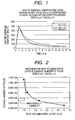
- the inventors have calculated, by the use of three-dimensional heat conduction simulation, a variation with the lapse of time in the surface temperature of the heat generating resistance member from the point of time of driving pulse application when the heat generating resistance member has been driven with a driving pulse width of 0.8 ⁇ s, with respect to a case where the heat accumulation layer is SiO 2 film having a film thickness of 2.5 ⁇ m, and a case where the heat accumulation layer is SiO 2 film having a film thickness of 1.5 ⁇ m, under a condition that the protection film is SiN film (insulating film) having a film thickness of 0.3 ⁇ m and Ta film (anti-cavitation film) having a film thickness of 0.23 ⁇ m.
- the result of the calculation is shown in Fig. 1.
- the maximum peak temperatures are of the order of 500°C in both, namely, substantially the same, but the temperature thereafter lowers more rapidly in the layer having a smaller film thickness. From this result, it is considered that by making the thickness of the heat accumulation layer small, the radiation characteristic can be improved without the heat transmission efficiency to the ink being reduced.
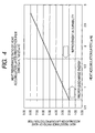
- the protection film is constituted by SiN film (insulating film) having a film thickness of 0.3 ⁇ m and Ta film (anti-cavitation film) having a film thickness of 0.23 ⁇ m, and the thickness of the heat accumulation layer differs have been made on an experimental basis, and the durability thereof, i.e., the driving pulse number until the ink comes to be not normally discharged, has been evaluated.
- Fig. 2 The result of the evaluation is shown in Fig. 2 as the relation between the thickness of the heat accumulation layer and the durable number of pulses. From Fig. 2, it has been newly found that when the film thickness of the heat accumulation layer is 1.7 ⁇ m or less, the durability is greatly improved. That is, the smaller is made the thickness of the heat generation layer, the more is improved the durability.
- Fig. 3 is a graph showing the relation between the thickness of the heat accumulation layer and the ink critical bubbling energy per unit area of the heat generating resistance member which has been obtained by the above-mentioned simulation.
- the ink critical bubbling energy per unit area of the heat generating resistance member becomes the index of the heat transmission efficiency to the ink.
- the ink critical bubbling energy is a critical heat energy value for the surface temperature of the heat generating resistance member to exceed 300°C which is the bubbling temperature of the ink, and the greater is this value, the worse is the heat transmission efficiency.
- the calculation has been carried out with heat energy application time (Pw) which is a driving electrical energization time changed to 0.5 ⁇ s to 3.0 ⁇ s.
- This heat energy application time is a proper time obtained as a condition that from the viewpoint of the recording speed of the ink jet head, it is necessary to drive the head at a high speed and the heat energy application time is not too short from driving pulse accuracy. Also, this time includes the proper condition of a high heat flux for effecting stable discharge in the discharging method of communicating a bubble with the atmosphere, i.e., the aforedescribed driving electrical energization time of 0.5 to 1.2 ⁇ s.
- the thickness of the heat accumulation layer should preferably be 0.7 ⁇ m or greater. Also, a heat accumulation layer thinner than 0.7 ⁇ m is difficult to form stably.
- the heat transmission efficiency becomes worse as the heat energy application time (Pw) becomes longer, and that the longer is Pw, the greater is the influence of the thickness of the heat accumulation layer.
- the thickness of the heat accumulation layer may be 1.0 to 1.7 ⁇ m without the efficiency being reduced, and for Pw of 0.5 to 1.2 ⁇ s which is the proper condition of a high heat flux, the thickness of the heat accumulation layer may be 0.7 to 1.5 ⁇ m without the efficiency being reduced, and these ranges are proper.
- the protection film is constituted by SiN film having a film thickness of 0.3 ⁇ m and Ta film having a film thickness of 0.23 ⁇ m, to make the radiation characteristic good without reducing the efficiency in order to improve durability, 0.7 to 1.7 ⁇ m is most proper as the thickness of a heat accumulation layer formed of SiO 2 , and further, for Pw of 0.5 to 1.2 ⁇ s, 0.7 to 1.5 ⁇ m is proper as the thickness of the heat accumulation layer, and 1.0 ⁇ m or less is more proper.
- the driving electrical energization is not limited to the case of a single pulse, but may be pulse driving divided into a plurality, and in this case, the total electrical energization time of the respective pulses corresponds to Pw.
- the relation shown in Fig. 3 shows that a result coinciding with the simulation has also been obtained in the aforedescribed heads made on an experimental basis.
- the materials and thicknesses of the protection film and the heat accumulation layer have been specifically shown, but the present invention is not restricted thereto.
- the present invention efficiently transmits the applied heat energy to the ink, and properly radiates heat to the heat accumulation layer and therefore, the above-described condition can be substituted for by the heat resistance ratio of the protection film and the heat accumulation layer.
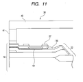
- Fig. 4 is a graph showing the relation between the thickness of the heat accumulation layer and the heat resistance ratio of the heat accumulation layer/the protection film in which the condition of the heat accumulation layer in the aforedescribed condition of the protection film has been substituted for by the heat resistance ratio of the heat accumulation layer and the protection film.
- the heat conductivity of each film at this time has been 1.2 w/m•K (according to the result of the measurement of the articles made on an experimental basis) for thin film SiN, 54 w/m•K for thin film Ta, and 1.38 w/m•K for thin film SiO 2 .
- the heat conductivity of the thin film Ta and the thin film SiO 2 use has been made of a value generally obtained by literature or the like.
- the heat resistance value of the laminated film is a result obtained by adding the heat resistance value of each film to one another.
- the film thickness condition of the heat accumulation layer i.e., 0.7 ⁇ m or greater and 1.7 ⁇ m or less
- the protection film comprising SiN film having a film thickness of 0.3 ⁇ m and Ta film having a film thickness of 0.23 ⁇ m
- the range of two times or greater and less than five times is proper as the ratio of the heat resistance of the heat accumulation layer under the heat generating resistance member to the heat resistance of the protection film on the heat generating resistance member.
- the protection film including the insulating film and the anti-cavitation film is formed on the upper layer of the heat generating resistance member, but inorganic film of SiN or the like used as the insulating film is inferior in ink resistance and mechanical resisting characteristic, and if a defect occurs to the anti-cavitation film, the ink enters therefrom to thereby corrode the heat generating resistance member and bring it to breakage. Accordingly, the life of the anti-cavitation film greatly affects durability. Taking tantalum typical as the anti-cavitation film as an example, it is observed that an oxide (oxidated layer) is formed on the surface of the anti-cavitation film subjected to an endurance test.
- the degree of oxidation can be known by such means as the discoloration of the surface of tantalum, the surface composition analysis by an electron probe micro analyzer (EPMA) or the like, or the observation of the cross-section of the film by a focused ion beam working observation apparatus (FIB).
- the oxidated layer is inferior in chemical and mechanical strength, and is exfoliated by the shock of cavitation.
- the anti-cavitation film has its damage enlarged while the oxidation and exfoliation are repeated and finally, the damage reaches the insulating layer. Also, in such a construction communicating a bubble with the atmosphere so that cavitation may not occur, durability is improved, but finally breakage results.
- the breakage of the heat generating resistance is caused by the oxidation of the anti-cavitation film in both of the mechanical factor and the chemical factor, and it is effective in improving durability to suppress this oxidating action.
- the oxidation of the anti-cavitation film occurs due to the ink being present on the anti-cavitation film under high heat, but the component of the ink is determined from the solvability of the dye and the fixing property to a printing medium and is low in the degree of freedom of selection and therefore, it is realistically effective as a measure for preventing oxidation to lower the surface temperature of the protection film. To lower the surface temperature of the protection film, there are the means of
- the film thicknesses and materials of the protection film and the heat accumulation layer are set so that the heat resistance value of the heat accumulation layer under the heat generating resistance member may be within the range of two times or greater and less than five times as great as the heat resistance value of the protection film on the heat generating resistance member, whereby it becomes possible to effectively prevent the deterioration of the protection film without reducing the heat transmission efficiency to the ink and improve the durability of the heat generating resistance member, and also improve the radiation characteristic, and driving for a very short driving electrical energization time of 0.5 to 2.0 ⁇ s, i.e., at a high frequency becomes possible.
- the cooling of the protection film is quick and therefore the surface temperature of the protection film is lowered during the occurrence of cavitation during the disappearance of the bubble after the discharge of the ink, or when the bubble communicates with the atmosphere, and as compared with the prior art, it also becomes possible to prevent the oxidation of the protection film.
- the cavitation destruction due to the re-boiling of the ink is a phenomenon which occurs in a case where the surface temperature of the protection film is 100°C or higher when the ink contacts with the surface of the protection film.
- attention is paid to the oxidation of the surface of the protection film, and this phenomenon occurs also at 100°C or lower, irrespective of the re-boiling of the ink.
- the center of the heat generating portion has the tendency that the highest reaching temperature becomes high and moreover, the peripheral portion thereof first cools during cooling and therefore, the center tends to be at a high temperature to the last.
- the ink contacts with this portion not only oxidation progresses, but also mechanical destruction due to the temperature difference from the surroundings is also accelerated, and this is not preferable. Therefore, more uniform heating and quick cooling are required.
- an edge shooter type in which the discharge direction is a direction parallel to the heat generating surface), such breakage of the center of the heat generating portion did not occur. This is considered to be because the inflow direction of the ink is parallel to the surface of the heat generating portion and the ink flows in from a side on which the temperature around the heat generating portion is low.
- Fig. 12 is a typical perspective view showing an example of the ink jet recording apparatus of the present invention.
- a lead screw 5004 formed with a spiral groove 5005 is rotatably journalled to a main body frame.
- the lead screw 5004 is rotatively driven through driving force transmitting gears 5009-5011 in operative association with the forward and reverse rotation of a drive motor 5013.
- a guide rail 5003 for slidably guiding a carriage HC is fixed to the main body frame.
- the carriage HC is provided with a pin (not shown) engaged with the spiral groove 5005, and the lead screw 5004 is rotated by the rotation of the drive motor 5013, whereby the carriage HC can be reciprocally moved in the directions of arrows a and b.
- a paper pressing plate 5002 presses a recording medium P against a platen roller 5000 over the direction of movement of the carriage HC.
- An ink jet recording unit IJC is mounted on the carriage HC.
- the ink jet recording unit IJC may take the form of a cartridge in which the above-described ink jet head is made integral with an ink tank IT, or a form in which they are detachably combined with each other as discrete members. Also, this ink jet recording unit IJC is fixedly supported on the carriage HC by positioning means and an electrical contact provided on the carriage HC, and is provided so as to be detachably mountable with respect to the carriage HC.
- Photocouplers 5007 and 5008 together constitute home position detecting means for confirming the presence of the lever 5006 of the carriage HC in this region and effecting the reversal or the like of the direction of rotation of the drive motor 5013.
- a cap member 5022 for capping the front surface (the surface in which the discharge port opens) of the ink jet head is supported by a supporting member 5016, and further is provided with suction means 5015, and effects the suction recovery of the ink jet head through an opening 5023 in the cap.
- a supporting plate 5019 is mounted on a main body supporting plate 5018, and a cleaning blade 5017 slidably supported on this supporting plate 5018 is moved back and forth by driving means, not shown.
- a lever 5021 is for starting the suction recovering operation of the ink jet head, and is moved with the movement of a cam 5020 which abuts against the carriage HC, and the movement thereof is controlled by a driving force from the motor 5013 being transmitted by the gear 5010 or conventional transmitting means such as latch changeover.
- the processes of capping, cleaning and suction recovery are adapted to be carried out at respective corresponding positions by the action of the lead screw 5004 when the carriage HC has been moved to a home position side area, but if design is made such that a desired operation is performed at well-known timing, any of them can be applied to the present example.
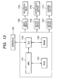
- Fig. 13 shows a block diagram of a control circuit for controlling the operation of the above-described ink jet recording apparatus.
- the control circuit shown in Fig. 13 has an interface 1700 to which a recording signal is inputted from an external device such as a computer, a controlling portion for governing the operation of the ink jet recording apparatus on the basis of the recording signal inputted through the interface 1700, a head driver 1705 for driving a recording head (ink jet head) 1708, a motor driver 1706 for driving a conveyance motor 1709 for conveying the recording medium (rotating the platen roller 5000 shown in Fig. 12), and a motor driver 1707 for driving a carrier motor 1710 (corresponding to the drive motor 5013 of Fig. 12).
- the controlling portion has a gate array (G.A.) 1704 for effecting the control of the supply of recording data to the recording head 1708 in response to the recording signal from the interface 1700, an MPU 1801, a ROM 1702 storing therein a control program the MPU 1701 executes, and DRAM 1703 preserving therein various data such as the aforementioned recording signal and the recording data supplied to the recording head.
- the gate array 1704 also effects the data forwarding control between the MPU 1701 and the DRAM 1703.
- the recording signal When the recording signal is inputted to the interface 1700, the recording signal is converted into recording data for recording between the gate array 1704 and the MPU 1701. Then, the conveyance motor 1709 and the carrier motor 1710 are driven by the respective motor drivers 1706 and 1707 and also, the recording head 1708 is driven in accordance with the recording data sent to the head driver 1705, whereby recording is effected.
- the driving electrical energization time of the aforedescribed heat generating resistance member is also controlled by the MPU 1701.
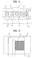
- Fig. 5 is a plan view of the essential portions of construction example 1 of the ink jet head suitably used in the present invention as it is seen from the discharge port side.
- Fig. 6 is a plan view of a base member showing on an enlarged scale one of the heat generating resistance members shown in Fig. 5.
- a nozzle material 10 is shown in a seen-through state so that the internal structure can be seen.
- the ink jet head 1 has the base member 20 formed with a plurality of heat generating resistance members 23, and the nozzle material 10 joined to the base member 20.
- the heat generating resistance members 23 are arranged in a row. In the case of an ink jet head for colors, however, they can also be arranged in a plurality of rows.
- discharge ports 11 are formed at locations opposed to the respective heat generating resistance members 23 with the centers thereof located on the centers of the heat generating resistance members 23.
- the nozzle material 10 is formed with a nozzle wall 13 partitioning adjacent ones of the heat generating resistance members 23, and by the base member 20 and the nozzle material 10 being joined together, a flow path to which the discharge port 11 opens is formed for each heat generating resistance member 23.
- a supply port (not shown) is formed through the base member 20 in order to supply the ink from the outside of this ink jet head 1 onto each heat generating resistance member 23.
- the supply port opens to an ink chamber common to the flow paths.
- a filter 29 which is a pillar-shaped structure is provided between the ink chamber and each flow path in order to block the entry of foreign substances into the ink jet head 1.
- Insulating film (not shown in Fig. 6) and anti-cavitation film 27 are provided so as to commonly cover all the heat generating resistance members 23 are arranged in a row. Further, as shown in Fig. 6, electrode wiring 25 is connected to the heat generating resistance members 23.
- the ink jet head 1 of this example is of the so-called side shooter type in which the heat generating resistance members 23 and the discharge ports 11 are opposed to each other.
- the discharging method of the ink jet head 1 of the side shooter type is roughly classified into a method of communicating a bubble produced by the driving of the heat generating resistance members 23 with the atmosphere, and a method of not communicating the bubble with the atmosphere.
- the present invention is applicable to both of these. In the latter discharging method, the produced bubble disappears without communicating with the atmosphere.
- Fig. 7 is a cross-sectional view of the ink jet head of Fig. 5 taken along the line VII-VII of Fig. 5.
- the ink jet head 1 of the present example will hereinafter be described with respect chiefly to the layer construction of the base member 20 with reference to Fig. 7.
- the base member 20 has a substrate 21 formed of silicon, a heat accumulation layer 22 formed on the surface thereof and serving also as electrical insulating film, a heat generating resistance member 23 partly formed on the heat accumulation layer 22, electrode wires 24, 25 for supplying electric power to the heat generating resistance member 23, insulating film 26 formed so as to cover the heat generating resistance member 23 and the heat accumulation layer 22, and anti-cavitation film 27 formed on a portion of the insulating film 26.
- Protection film is constituted by the insulating film 26 and the anti-cavitation film 27.
- the insulating film 26 is constituted by SiN film having a film thickness of 0.3 ⁇ m
- the anti-cavitation film 27 is constituted by Ta film having a film thickness of 0.23 ⁇ m. Accordingly, the layer thickness a of the protection film is 0.53 ⁇ m.
- the heat accumulation layer 22 is of three-layer structure in which thermally oxidated film 22a, inter-layer film 22b and inter-layer film 22c are laminated in succession from the substrate 21 side.
- the thermally oxidated film 22a is partly formed so as not to exist in an area opposed to the heat generating resistance member 23, and in the present example, it is only two layers, i.e., the inter-layer film 22b and the inter-layer film 22c that substantially functions as the heat accumulation layer 22.
- the thermally oxidated film 22a is constituted by SiO 2 film formed by the thermal oxidating method
- the inter-layer film 22b and the inter-layer film 22c are constituted by SiO 2 formed by the CVD method.
- the film thickness of each of the inter-layer film 22b and the inter-layer film 22c is 0.7 ⁇ m
- the layer thickness b of the heat accumulation layer 22 beneath the heat generating resistance member 23 in the present example is 1.4 ⁇ m.
- the heat generating resistance member 23 in the present example is constituted by TaSiN having a film thickness of 500 ⁇ . Also, the electrode wires 24 and 25 are formed of AlCu.
- the nozzle material 10 is joined onto the base member 20 and forms an ink chamber 12 constituting a portion of the flow path between the heat generating resistance member 23 and the discharge port 11.
- the protection film is constituted by insulating film formed of SiN and having a film thickness of 0.3 ⁇ m, and anti-cavitation film formed of Ta and having a film thickness of 0.23 ⁇ m
- the heat accumulation layer is constituted by SiO 2 film having a film thickness of about 1 ⁇ m and inter-layer film comprising two layers of SiO 2 each having a film thickness of about 1 ⁇ m, and the total thickness thereof is 3 ⁇ m.
- the inter-layer film 22b, 22c serves also as the insulation of other circuit such as the insulation of the electrode wires 24 and 25 and therefore, for the purpose of stable film forming, the thickness of each layer need be 0.7 ⁇ m or greater, and in the present example, each layer is formed with a minimum thickness, but the thickness of the whole of the heat accumulation layer 22 can also be 1.4 to 1.7 ⁇ m.
- the material of the film constituting the heat accumulation layer, the number of layers and structure of the heat accumulation layer 22 are arbitrarily changeable within such a range that the heat resistance value of the heat accumulation layer 22 is two times or greater and less than five times as great as the heat resistance value of the protection film.
- at least one layer of the heat accumulation layer 22 can be SiO x film or boro-phosphosilicate glass (BPSG) film, and as a film forming method therefor, use can be made of any method such as the thermally oxidating method or the CVD method.
- the anti-cavitation film 27 is constituted by a single layer of Ta film, but can also be of laminated structure of a plurality layers of thin film. Thereby, the covering property on a level difference portion produced on heat generating resistance members 23 by the electrode wire 25 can be improved. This also holds true when the insulating film 26 is of laminated structure of a plurality of layers of thin film. Also, the anti-cavitation film 27 can be formed by film of TaCr, Cr, Ir, Pt or Ir alloy, besides Ta. In a case where the anti-cavitation film 27 is of laminated structure of a plurality of layers of film, at least one layer thereof can also be formed of one of these materials.
- the heat generating resistance member 23 is formed of TaSiN having a film thickness of 0.05 ⁇ m, this is not restrictive, but the heat generating resistance member 23 can also be formed of TaN and further, it has been found that if the material forming the heat generating resistance member 23 is a material having such a thickness of 0.01 to 0.1 ⁇ m that the balance of the heat resistance of the protection film and the heat accumulation layer 22 on and under the heat generating resistance member 23 is not broken, there will arise no problem about durability and high frequency driving in which the driving electrical energization time is within a range of 0.5 ⁇ s to 2.0 ⁇ s.
- the plane size of the heat generating resistance member 23 is a square of 26 ⁇ m ⁇ 26 ⁇ m.
- the size of the heat generating resistance member 23 is not restricted thereto, but it has been confirmed that up to at least 16 ⁇ m ⁇ 16 ⁇ m to 39 ⁇ m ⁇ 39 ⁇ m poses no problem.
- the shape of the heat generating resistance member 23 is not restricted to a square, but can be a rectangle.
- the number of heat generating resistance members 23 per discharge port 12 can be plural, and for example, there can be adopted a construction in which two rectangular members of 10 ⁇ m ⁇ 24 ⁇ m are connected in series.
- the heat resistance ratio of the heat accumulation layer 22 to the protection film on and under the heat generating resistance member 23 is made proper and moreover, such high frequency driving that the driving electrical energization time is within the range of 0.5 ⁇ s to 2.0 ⁇ s is effected, whereby irrespective of the discharging method being a method of communicating a bubble produced by the driving of the heat generating resistance member 23 with the atmosphere or a method of not communicating the bubble with the atmosphere, there can be obtained an effect not greatly differing but equally excellent in effectively preventing the deterioration of the protection film without reducing the heat transmission efficiency to the ink, and realizing the longer life of the heat generating resistance member and also, improving the radiation characteristic and realizing the driving at a higher frequency.
- Fig. 8 is a cross-sectional view similar to Fig. 7 but showing construction example 2 of the ink jet head suitably used in the present invention.
- constituents similar to those in Fig. 7 are given the same reference characters as those in Fig. 7.
- the ink jet head of the present example differs from construction example 1 of the ink jet head in that the heat accumulation layer 22 is formed so that of the two layers of inter-layer film 22b and 22c constituting a portion of the heat accumulation layer 22, only the inter-layer film 22b may be partly formed like the thermally oxidated film 22a, and only the other inter-layer film 22c may exist beneath the heat generating resistance member 23. That is, in the present example, it is a single layer of inter-layer film 22c that substantially functions as the heat accumulation layer 22. In the other points, the construction of the present example is the same as that of construction example 1 of the ink jet head.
- the film thickness of the inter-layer film 22c is 0.7 ⁇ m and accordingly, the thickness of the heat accumulation layer 22 beneath the heat generating resistance member 23 also is 0.7 ⁇ m.
- the inter-layer film 22c is formed of SiO 2 as in construction example 1 of the ink jet head, and the protection film on the heat generating resistance member 23, i.e., the insulating film 26 and the anti-cavitation film 27 are also formed of and with materials and film thicknesses similar to those in construction example 1 of the ink jet head and therefore, the heat resistance ratio of the heat accumulation layer 22 to the protection film in the present example is 2.00.
- the heat generating resistance member 23 when as previously described, the heat generating resistance member 23 is driven for a driving electrical energization time within the range of 0.5 ⁇ s to 2.0 ⁇ s, durability can be further improved as compared with construction example 1 of the ink jet head.
- the driving electrical energization time be 0.5 ⁇ s to 1.2 ⁇ s.
- the thickness of the inter-layer film 22c, i.e., the heat accumulation layer 22, can be changed within a range of 0.7 to 1.4 ⁇ m.
- Fig. 9 is a cross-sectional view similar to Fig. 7 but showing construction example 3 of the ink jet head suitably used in the present invention, and in Fig. 9, constituents similar to those in Fig. 7 are given the same reference characters as those in Fig. 7.
- the ink jet head of the present example differs from construction example 1 of the ink jet head in that in the heat accumulation layer 22, the thermally oxidated film 22a is not formed in a region corresponding to the flow path.
- the materials, film thicknesses and other constructions of the anti-cavitation film 27, the insulating film 26 and the inter-layer film 22b, 22c are the same as those in construction example 1 of the ink jet head.
- the thermally oxidated film 22a is difficult to form by a thin pattern, as compared with the inter-layer film 22b, 22c which can be formed by etching and therefore, if the thermally oxidated film 22a is left in the region corresponding to the flow path, the flow path tends to become long.
- the thermally oxidated film 22a is absent in the region corresponding to the flow path and therefore, as compared with construction example 1 of the ink jet head, the flow path can be shortened.
- an ink chamber (not shown) leading to the shortened flow path can be brought close to the heat generating resistance member 23, and the supply of the ink from the ink chamber onto the heat generating resistance member 23 can be effected efficiently.
- the degree of freedom of design such as coping with high frequency driving can be further improved.
- the thermally oxidated film 22a need not always be provided in the present example.
- Fig. 10 is a cross-sectional view similar to Fig. 7 but showing construction example 4 of the ink jet head suitably used in the present invention, and in Fig. 10, constituents similar to those in Fig. 7 are given the same reference characters as those in Fig. 7.
- the ink jet head of the present example also differs in the structure of the heat accumulation layer 22 from the above-described examples, and specifically, in a portion corresponding to the heat generating portion, the inter-layer film 22b adjacent to the thermally oxidated film 22a is removed by etching and also, the thermally oxidated film 22a has its film thickness made small by half-etching.
- the inter-layer film 22c and the left portion of the thermally oxidated film 22a that substantially functions as the heat accumulation layer 22, and the total thickness of the heat accumulation layer 22 can be considered to be the sum of the film thickness of the inter-layer film 22a and the film thickness of the remaining portion of the thermally oxidated film 22a.
- the present example is a construction effective to make the total thickness of the heat accumulation layer 22 while keeping the film thickness of the inter-layer film 22c relatively great.
- By making the inter-layer film 22c thick it is possible to make the thickness of the electrode wire 24 beneath the inter-layer film 22c great, and decrease the wiring resistance of the electrode wire 24.
- a through-hole is formed in the base member 20 formed of silicon from a surface opposite to the surface of the base member 20 to which the nozzle member 10 is joined, and a portion in which this through-hole opens is used as a supply port (see Fig. 5).
- a method by the anisotropic etching of mono-crystalline silicon is excellent in respect of dimensional accuracy.
- an ink chamber of a square cone having (111) surface as a wall surface is obtained by anisotropic etching.
- the (111) surface is inclined by about 54° with respect to the surface of the substrate, and assumes a cross-section indicated by dotted line in Fig. 10.
- a crystal defect or the like may rarely exist in a silicon substrate. If also in the formation of a through-hole by anisotropic etching, a crystal defect or the like exists, etching will preferentially progress only in that portion and dimensional abnormality will occur to a portion of. the ink chamber. In order to solve this problem, it is desirable that as shown in Fig. 10, a sacrifice layer 28 higher in etching speed than mono-crystalline silicon be formed in a region wherein the through-hole of the base member 20 after the inter-layer film 22b has been removed is formed.
- the sacrifice layer 28 is used as an etching stop layer because when unevenness has occurred to the etching time in the manufacturing process, or when the unevenness of the etching speed of a polycrystalline silicon layer has occurred, the through-hole causes unevenness to the design value. As long as the above-mentioned unevenness does not greatly occur, the sacrifice layer may be dispensed with, but the details of the sacrifice layer will be described below.
- the sacrifice layer 28 is removed by the formation of the through-hole.
- Polycrystalline silicon or aluminum is suitable as the sacrifice layer 28. When aluminum is used, the sacrifice layer 28 can be formed simultaneously with the electrode wire 24 and therefore, there is no increase in the number of steps due to the sacrifice layer 28 being formed, and this is also advantageous in suppressing the rise of the manufacturing cost.
- etching time is set a little long with the unevenness of the thickness of the silicon substrate taken into account, the through-hole tends to become larger than the design value by overetching.
- silicon oxide works as an etching stop layer because it is insoluble in etching liquid (e.g. TMAH: tetramethyl ammonium hydroxide), and as indicated by dot-and-dash line in Fig.
- the enlargement of the through-hole is limited to a position contacting with the end of the thermally oxidated film 22a. Even in the case of the same film constituting the heat accumulation layer 22, such BPSG film as is used in the inter-layer film 22b, 22c or film by plasma CVD is not fine and is dissolved in the etching liquid and therefore, is not suitable as the etching stop layer.
- the thermally oxidated film 22a can be utilized as the etching stop layer when the through-hole is formed by anisotropic etching and therefore, if the thermally oxidated film 22a is formed so as to surround the area in which the through-hole is formed, the sacrifice layer 28 need not always be provided.
- the heat resistance below the heat generating resistance member 23 can be within a predetermined range relative to the heat resistance above the heat generating resistance member 23, and the respective film thicknesses may be determined by other requirements.
- the film thicknesses had better be great, but to secure conduction between the layers by a contact hole, it is better to make the film thickness of the inter-layer film to thereby prevent the opening in the level difference portion of the upper layer electrode.
- the present invention is not restricted thereto, but can also be applied to an ink jet head 30 of a so-called edge shooter type as shown in Fig. 11.
- the ink jet head 30 of the edge shooter type like the ink jet head of the side shooter type, has a base member 50 and a nozzle material 40 joined thereto, but the structure of the nozzle material 40 differs from that of the ink jet head of the side shooter type. Specifically, a discharge port 41 is formed not at a location opposed to a heat generating resistance member 53, but on the end surface of the nozzle material 40, and the ink is discharged in a direction substantially parallel to the upper surface of the base member 50.
- the heat resistance of the heat accumulation layer below the heat generating resistance member is set to a range of two times or greater and less than five times as great as the heat resistance of the protection film above the heat generating resistance member, the occurrence of "scorching" by the heat on the heat generating resistance member can be suppressed without the heat transmission efficiency to the ink being reduced and also, the deterioration of the protection film can be prevented to thereby realize the longer life of the heat generating resistance member. Also, the radiation characteristic can be improved by the prevention of re-boiling and heat accumulation, and driving at a higher frequency can be realized.
- the durability being improved, it is unnecessary to increase the number of the heat generating resistance members or arrange the heat generating resistance members indiscriminately at high density even if the size of the ink droplet discharged is made small, and this leads to a general reduction in cost, including the simplification of the manufacturing process of the ink jet head and the driving circuit, etc. of the ink jet head. Also, there is the effect that even if there is a constant tolerance in the thickness of the heat accumulation layer, the heat transmission efficiency to the ink is not reduced and therefore, the manufacturing tolerance margin of the ink jet head is increased and also, the yield is improved and the degree of freedom of design is also improved.
Landscapes
- Particle Formation And Scattering Control In Inkjet Printers (AREA)
Abstract
Description
Claims (19)
- A base member for an ink jet head in which a heat accumulation layer, a heat generating member generating heat energy used to discharge ink, and protection film for protecting said heat generating member are formed in succession on a substrate, wherein the heat resistance value of a portion of said heat accumulation layer which is under said heat generating member is two times or greater and less than five times as great as the heat resistance value of a portion of said protection film which is on said heat generating member.
- A base member for an ink jet head according to Claim 1, wherein said heat accumulation layer comprises a plurality of layers of thin film.
- A base member for an ink jet head according to Claim 2, wherein at least one layer of the thin film forming said heat accumulation layer is SiOx film or BPSG film.
- A base member for an ink jet head according to any one of Claims 1 to 3, wherein said protection film comprises a plurality of layers of thin film.
- A base member for an ink jet head according to any one of Claims 1 to 4, wherein said protection film includes SiN film.
- A base member for an ink jet head according to any one of Claims 1 to 4, wherein said protection film includes Ta film.
- A base member for an ink jet head according to any one of Claims 1 to 4, wherein said protection film includes film formed of TaCr, Cr, Ir, Pt or Ir alloy.
- A base member for an ink jet head according to Claim 1, wherein said protection film has laminated structure including at least SiN film having a film thickness of 0.3 µm, and Ta film having a film thickness of 0.23 µm, and said heat accumulation layer has a total thickness of 0.7 µm or greater and 1.7 µm or less and includes at least one layer of Si oxide film.
- A base member for an ink jet head according to Claim 8, wherein said heat generating member is formed of TaSiN or TaN and has a thickness of 0.01 µm or greater and 0.1 µm or less.
- An ink jet head having a base member in which a heat accumulation layer, a heat generating member generating heat energy used to discharge ink, and a protection film for protecting said heat generating member are formed in succession on a substrate, and having a discharge port for discharging the ink therethrough provided correspondingly to said heat generating member, wherein the heat resistance value of a portion of said heat accumulation layer which is under said heat generating member is two times or greater and less than five times as great as the heat resistance value of a portion of said protection film which is on said heat generating member.
- An ink jet head according to Claim 10, wherein said heat accumulation layer is a plurality of layers of thin film.
- An ink jet head according to Claim 11, wherein said heat accumulation layer does not include thermally oxidated film in a region corresponding to a flow path communicating with said discharge port.
- An ink jet head according to Claim 11, wherein said substrate is formed of silicon, and thermally oxidated film is provided around a through-hole formed in said base member for supplying the ink onto said heat generating member.
- An ink jet head according to Claim 10, wherein said protection film has laminated structure including at least SiN film having a film thickness of 0.3 µm, and Ta film having a film thickness of 0.23 µm, and said heat accumulation layer has a total thickness of 0.7 µm or greater and 1.7 µm or less, and includes at least one layer of Si oxide film.
- A driving method for an ink jet head for driving, by the use of an ink jet head having a base member in which a heat accumulation layer, a heat generating member generating heat energy used to discharge ink, and a protection film for protecting said heat generating member are formed in succession on a substrate, and having a discharge port for discharging the ink therethrough provided correspondingly to said heat generating member, wherein the heat resistance value of a portion of said heat accumulation layer which is under said heat generating member is two times or greater and less than five times as great as the heat resistance value of a portion of said protection film which is on said heat generating member, said heat generating member for a driving electrical energization time of 5 µs or greater and 2.0 µs or less to thereby discharge the ink from said discharge port.
- A driving method according to Claim 15, wherein said driving electrical energization time is 0.5 µs or greater and 1.2 µs or less.
- A driving method according to Claim 15 or 16, wherein the driving of said heat generating member for discharging the ink is the driving by the application of a plurality of pulses, and said driving electrical energization time is the total electrical energization time of said plurality of pulses.
- A driving method according to Claim 16, wherein by the use of the ink jet head wherein said protection film has laminated structure including at least SiN film having a film thickness of 0.3 µm, and Ta film having a film thickness of 0.23 µm, and said heat accumulation layer has a total thickness of 0.7 µm or greater and 1.7 µm or less and includes at least one layer of Si oxide film, said heat generating member is driven for a driving electrical energization time of 0.5 - 2.0 µs to thereby discharge the ink from said discharge port.
- An ink jet recording apparatus provided with:an ink jet head having a base member in which a heat accumulation layer, a heat generating member generating heat energy used to discharge ink, and protection film for protecting said heat generating member are formed in succession on a substrate, and having a discharge port for discharging the ink therethrough provided correspondingly to said heat generating member, wherein the heat resistance value of a portion of said heat accumulation layer which is under said heat generating member is two times or greater and less than five times as great as the heat resistance value of a portion of said protection film which is on said heat generating member; anddriving means for driving said heat generating member for a driving electrical energization time of 0.5 µs or greater and 2.0 µs or less.
Applications Claiming Priority (2)
| Application Number | Priority Date | Filing Date | Title |
|---|---|---|---|
| JP2003434520 | 2003-12-26 | ||
| JP2003434520 | 2003-12-26 |
Publications (2)
| Publication Number | Publication Date |
|---|---|
| EP1547777A1 true EP1547777A1 (en) | 2005-06-29 |
| EP1547777B1 EP1547777B1 (en) | 2011-06-08 |
Family
ID=34545104
Family Applications (1)
| Application Number | Title | Priority Date | Filing Date |
|---|---|---|---|
| EP04029556A Expired - Lifetime EP1547777B1 (en) | 2003-12-26 | 2004-12-14 | Ink jet head, method of driving the ink jet head, and ink jet recording apparatus |
Country Status (5)
| Country | Link |
|---|---|
| US (1) | US7216961B2 (en) |
| EP (1) | EP1547777B1 (en) |
| KR (1) | KR20050067035A (en) |
| CN (1) | CN100346972C (en) |
| TW (1) | TWI250086B (en) |
Families Citing this family (10)
| Publication number | Priority date | Publication date | Assignee | Title |
|---|---|---|---|---|
| JP4724490B2 (en) * | 2005-08-09 | 2011-07-13 | キヤノン株式会社 | Liquid discharge head |
| US7681990B2 (en) * | 2006-03-17 | 2010-03-23 | Canon Kabushiki Kaisha | Liquid jetting apparatus and method for switchably driving heaters |
| TWI332904B (en) | 2007-11-29 | 2010-11-11 | Internat United Technology Company Ltd | Thermal inkjet printhead chip structure and manufacture method thereof |
| US7959262B2 (en) * | 2008-05-26 | 2011-06-14 | Canon Kabushiki Kaisha | Ink jet recording head substrate, and ink jet recording head including the substrate |
| JP6039411B2 (en) | 2012-12-27 | 2016-12-07 | キヤノン株式会社 | Inkjet head substrate, inkjet head, and inkjet head manufacturing method |
| CN105026165B (en) * | 2013-02-27 | 2017-06-09 | 京瓷株式会社 | Thermal head and thermal printer |
| WO2017183389A1 (en) * | 2016-04-18 | 2017-10-26 | コニカミノルタ株式会社 | Inkjet head, head module, and inkjet recording device |
| US10322578B2 (en) | 2017-06-20 | 2019-06-18 | Canon Kabushiki Kaisha | Liquid ejection head and liquid ejection apparatus |
| JP7134752B2 (en) * | 2018-07-06 | 2022-09-12 | キヤノン株式会社 | liquid ejection head |
| JP7654512B2 (en) * | 2021-09-08 | 2025-04-01 | キヤノン株式会社 | LIQUID EJECTION APPARATUS AND CONTROL METHOD |
Citations (8)
| Publication number | Priority date | Publication date | Assignee | Title |
|---|---|---|---|---|
| US5580468A (en) | 1991-07-11 | 1996-12-03 | Canon Kabushiki Kaisha | Method of fabricating head for recording apparatus |
| EP0769379A1 (en) | 1995-10-19 | 1997-04-23 | Lexmark International, Inc. | Thermal ink jet cartridge and thermal semiconductor chip |
| JPH09187936A (en) * | 1996-01-08 | 1997-07-22 | Canon Inc | Inkjet recording head substrate, inkjet recording head, and inkjet recording apparatus |
| JP2001171127A (en) * | 1999-10-05 | 2001-06-26 | Canon Inc | Substrate for inkjet recording head, inkjet recording head, inkjet recording unit, and inkjet recording apparatus |
| JP2002011886A (en) * | 2000-06-30 | 2002-01-15 | Canon Inc | Substrate for inkjet recording head, inkjet recording head, and method for producing substrate for head |
| US20020024561A1 (en) | 2000-08-04 | 2002-02-28 | Hideyuki Sugioka | Ink jet recording head and ink jet recording apparatus |
| US20030137562A1 (en) | 1996-02-07 | 2003-07-24 | Kawamura Naoto A. | Fully integrated thermal inkjet printhead having etched back PSG layer |
| US20030222938A1 (en) | 2002-05-31 | 2003-12-04 | Anderson Frank Edward | Heater configuration for tri-color heater chip |
Family Cites Families (5)
| Publication number | Priority date | Publication date | Assignee | Title |
|---|---|---|---|---|
| CA1127227A (en) * | 1977-10-03 | 1982-07-06 | Ichiro Endo | Liquid jet recording process and apparatus therefor |
| JPH0624855B2 (en) * | 1983-04-20 | 1994-04-06 | キヤノン株式会社 | Liquid jet recording head |
| DE69402901T2 (en) | 1993-02-26 | 1997-11-20 | Canon Kk | Inkjet printhead, inkjet head cartridge and printing device |
| US6435660B1 (en) | 1999-10-05 | 2002-08-20 | Canon Kabushiki Kaisha | Ink jet recording head substrate, ink jet recording head, ink jet recording unit, and ink jet recording apparatus |
| JP4532705B2 (en) | 2000-09-06 | 2010-08-25 | キヤノン株式会社 | Inkjet recording head |
-
2004
- 2004-12-14 EP EP04029556A patent/EP1547777B1/en not_active Expired - Lifetime
- 2004-12-16 TW TW093139200A patent/TWI250086B/en not_active IP Right Cessation
- 2004-12-16 US US11/012,186 patent/US7216961B2/en not_active Expired - Fee Related
- 2004-12-24 KR KR1020040111600A patent/KR20050067035A/en not_active Ceased
- 2004-12-24 CN CNB200410011487XA patent/CN100346972C/en not_active Expired - Fee Related
Patent Citations (8)
| Publication number | Priority date | Publication date | Assignee | Title |
|---|---|---|---|---|
| US5580468A (en) | 1991-07-11 | 1996-12-03 | Canon Kabushiki Kaisha | Method of fabricating head for recording apparatus |
| EP0769379A1 (en) | 1995-10-19 | 1997-04-23 | Lexmark International, Inc. | Thermal ink jet cartridge and thermal semiconductor chip |
| JPH09187936A (en) * | 1996-01-08 | 1997-07-22 | Canon Inc | Inkjet recording head substrate, inkjet recording head, and inkjet recording apparatus |
| US20030137562A1 (en) | 1996-02-07 | 2003-07-24 | Kawamura Naoto A. | Fully integrated thermal inkjet printhead having etched back PSG layer |
| JP2001171127A (en) * | 1999-10-05 | 2001-06-26 | Canon Inc | Substrate for inkjet recording head, inkjet recording head, inkjet recording unit, and inkjet recording apparatus |
| JP2002011886A (en) * | 2000-06-30 | 2002-01-15 | Canon Inc | Substrate for inkjet recording head, inkjet recording head, and method for producing substrate for head |
| US20020024561A1 (en) | 2000-08-04 | 2002-02-28 | Hideyuki Sugioka | Ink jet recording head and ink jet recording apparatus |
| US20030222938A1 (en) | 2002-05-31 | 2003-12-04 | Anderson Frank Edward | Heater configuration for tri-color heater chip |
Non-Patent Citations (3)
| Title |
|---|
| PATENT ABSTRACTS OF JAPAN vol. 1997, no. 11 28 November 1997 (1997-11-28) * |
| PATENT ABSTRACTS OF JAPAN vol. 2000, no. 23 10 February 2001 (2001-02-10) * |
| PATENT ABSTRACTS OF JAPAN vol. 2002, no. 05 3 May 2002 (2002-05-03) * |
Also Published As
| Publication number | Publication date |
|---|---|
| TWI250086B (en) | 2006-03-01 |
| EP1547777B1 (en) | 2011-06-08 |
| US20050140732A1 (en) | 2005-06-30 |
| CN100346972C (en) | 2007-11-07 |
| TW200526416A (en) | 2005-08-16 |
| US7216961B2 (en) | 2007-05-15 |
| KR20050067035A (en) | 2005-06-30 |
| CN1636734A (en) | 2005-07-13 |
Similar Documents
| Publication | Publication Date | Title |
|---|---|---|
| US8491087B2 (en) | Circuit board for ink jet head, ink jet head having the same, method for cleaning the head and ink jet printing apparatus using the head | |
| US8191988B2 (en) | Liquid ejection head, liquid-ejection head substrate, liquid ejecting apparatus including liquid ejection head, and method of cleaning liquid ejection head | |
| KR100229123B1 (en) | An ink jet head substrate, an ink jet head, an ink jet apparatus, and a method for manufacturing an ink jet recording head | |
| US7980656B2 (en) | Liquid ejection head | |
| JP3576888B2 (en) | Substrate for inkjet head, inkjet head, and inkjet apparatus | |
| KR0156612B1 (en) | Substrate for ink jet head, ink jet head, ink jet pen, and ink jet apparatus | |
| US7216961B2 (en) | Ink jet head having heat accumulation layer and protection film method of driving thereof and ink jet recording apparatus provided therewith | |
| US6435660B1 (en) | Ink jet recording head substrate, ink jet recording head, ink jet recording unit, and ink jet recording apparatus | |
| US6454379B1 (en) | Liquid discharge head and liquid discharge apparatus that uses the liquid discharge head, and discharge volume correction method for the liquid discharge head | |
| JP6230290B2 (en) | Liquid discharge head substrate, liquid discharge head, and method for manufacturing liquid discharge head substrate | |
| JP3618965B2 (en) | Substrate for liquid jet recording head, method for manufacturing the same, and liquid jet recording apparatus | |
| US7172268B2 (en) | Ink jet head, method for driving the same, and ink jet recording apparatus | |
| JP3155423B2 (en) | Heating resistor, base for liquid ejection head including the heating resistor, liquid ejection head including the base, and liquid ejection apparatus including the liquid ejection head | |
| JP2000280477A (en) | Ink jet recording head, head cartridge on which the ink jet recording head is mounted, and recording apparatus | |
| JP3554148B2 (en) | Substrate for inkjet recording head, inkjet recording head, and inkjet recording apparatus | |
| JP2005205891A (en) | Substrate for inkjet head, inkjet head, driving method of inkjet head, and inkjet recording apparatus | |
| JP2005205892A (en) | Substrate for inkjet head, inkjet head, driving method of inkjet head, and inkjet recording apparatus | |
| JP2004216889A (en) | Heating resistor thin film, substrate for inkjet head using the same, inkjet head and inkjet device | |
| JPH09201965A (en) | Heating resistor, ink jet recording head substrate, ink jet recording head, and ink jet recording apparatus | |
| JP2828525B2 (en) | Method for manufacturing liquid jet recording head, liquid jet recording head manufactured by the method, and liquid jet recording apparatus equipped with the liquid jet recording head | |
| JPH0531903A (en) | Ink jet head substrate, ink jet head using the same, and ink jet apparatus equipped with the ink jet head | |
| JP5590906B2 (en) | Manufacturing method of substrate for liquid discharge head | |
| JPH11334077A (en) | Substrate for inkjet head, inkjet head, inkjet device, and method of manufacturing substrate for inkjet head | |
| JPH11198376A (en) | Substrate for inkjet recording head, method of manufacturing the same, and inkjet recording apparatus using the same | |
| JP2004209751A (en) | Heating resistor thin film, ink jet head and ink jet device using the same, and methods of manufacturing these |
Legal Events
| Date | Code | Title | Description |
|---|---|---|---|
| PUAI | Public reference made under article 153(3) epc to a published international application that has entered the european phase |
Free format text: ORIGINAL CODE: 0009012 |
|
| AK | Designated contracting states |
Kind code of ref document: A1 Designated state(s): AT BE BG CH CY CZ DE DK EE ES FI FR GB GR HU IE IS IT LI LT LU MC NL PL PT RO SE SI SK TR |
|
| AX | Request for extension of the european patent |
Extension state: AL BA HR LV MK YU |
|
| 17P | Request for examination filed |
Effective date: 20051229 |
|
| AKX | Designation fees paid |
Designated state(s): DE FR GB IT |
|
| 17Q | First examination report despatched |
Effective date: 20071102 |
|
| GRAP | Despatch of communication of intention to grant a patent |
Free format text: ORIGINAL CODE: EPIDOSNIGR1 |
|
| GRAS | Grant fee paid |
Free format text: ORIGINAL CODE: EPIDOSNIGR3 |
|
| GRAA | (expected) grant |
Free format text: ORIGINAL CODE: 0009210 |
|
| AK | Designated contracting states |
Kind code of ref document: B1 Designated state(s): DE FR GB IT |
|
| REG | Reference to a national code |
Ref country code: GB Ref legal event code: FG4D |
|
| REG | Reference to a national code |
Ref country code: DE Ref legal event code: R096 Ref document number: 602004032951 Country of ref document: DE Effective date: 20110721 |
|
| PLBE | No opposition filed within time limit |
Free format text: ORIGINAL CODE: 0009261 |
|
| STAA | Information on the status of an ep patent application or granted ep patent |
Free format text: STATUS: NO OPPOSITION FILED WITHIN TIME LIMIT |
|
| 26N | No opposition filed |
Effective date: 20120309 |
|
| PG25 | Lapsed in a contracting state [announced via postgrant information from national office to epo] |
Ref country code: IT Free format text: LAPSE BECAUSE OF FAILURE TO SUBMIT A TRANSLATION OF THE DESCRIPTION OR TO PAY THE FEE WITHIN THE PRESCRIBED TIME-LIMIT Effective date: 20110608 |
|
| REG | Reference to a national code |
Ref country code: DE Ref legal event code: R097 Ref document number: 602004032951 Country of ref document: DE Effective date: 20120309 |
|
| REG | Reference to a national code |
Ref country code: FR Ref legal event code: ST Effective date: 20120831 |
|
| PG25 | Lapsed in a contracting state [announced via postgrant information from national office to epo] |
Ref country code: FR Free format text: LAPSE BECAUSE OF NON-PAYMENT OF DUE FEES Effective date: 20120102 |
|
| PGFP | Annual fee paid to national office [announced via postgrant information from national office to epo] |
Ref country code: GB Payment date: 20171228 Year of fee payment: 14 |
|
| PGFP | Annual fee paid to national office [announced via postgrant information from national office to epo] |
Ref country code: DE Payment date: 20180228 Year of fee payment: 14 |
|
| REG | Reference to a national code |
Ref country code: DE Ref legal event code: R119 Ref document number: 602004032951 Country of ref document: DE |
|
| GBPC | Gb: european patent ceased through non-payment of renewal fee |
Effective date: 20181214 |
|
| PG25 | Lapsed in a contracting state [announced via postgrant information from national office to epo] |
Ref country code: DE Free format text: LAPSE BECAUSE OF NON-PAYMENT OF DUE FEES Effective date: 20190702 |
|
| PG25 | Lapsed in a contracting state [announced via postgrant information from national office to epo] |
Ref country code: GB Free format text: LAPSE BECAUSE OF NON-PAYMENT OF DUE FEES Effective date: 20181214 |