EP1547730B1 - Storage rack - Google Patents
Storage rack Download PDFInfo
- Publication number
- EP1547730B1 EP1547730B1 EP03029819A EP03029819A EP1547730B1 EP 1547730 B1 EP1547730 B1 EP 1547730B1 EP 03029819 A EP03029819 A EP 03029819A EP 03029819 A EP03029819 A EP 03029819A EP 1547730 B1 EP1547730 B1 EP 1547730B1
- Authority
- EP
- European Patent Office
- Prior art keywords
- trays
- flat accessories
- storage rack
- boxes
- flat
- Prior art date
- Legal status (The legal status is an assumption and is not a legal conclusion. Google has not performed a legal analysis and makes no representation as to the accuracy of the status listed.)
- Expired - Lifetime
Links
- 229920003023 plastic Polymers 0.000 claims abstract description 6
- 239000004033 plastic Substances 0.000 claims abstract description 6
- 230000037431 insertion Effects 0.000 claims 2
- 238000003780 insertion Methods 0.000 claims 2
- 230000002093 peripheral effect Effects 0.000 claims 1
- 230000001419 dependent effect Effects 0.000 description 1
Images


Classifications
-
- B—PERFORMING OPERATIONS; TRANSPORTING
- B25—HAND TOOLS; PORTABLE POWER-DRIVEN TOOLS; MANIPULATORS
- B25H—WORKSHOP EQUIPMENT, e.g. FOR MARKING-OUT WORK; STORAGE MEANS FOR WORKSHOPS
- B25H3/00—Storage means or arrangements for workshops facilitating access to, or handling of, work tools or instruments
- B25H3/02—Boxes
- B25H3/021—Boxes comprising a number of connected storage elements
- B25H3/023—Boxes comprising a number of connected storage elements movable relative to one another for access to their interiors
- B25H3/025—Boxes comprising a number of connected storage elements movable relative to one another for access to their interiors by rotation about a common axis
Definitions
- the present invention relates to storage racks according to the preamble of claims 1 and 5;
- Various storage boxes are known for keeping accessories and small items. These storage boxes commonly comprise a box body defining a plurality of compartments for keeping different accessories, and a cover hinged to the box body. Several storage boxes may be joined, forming a storage rack.
- a loose-leaf type storage rack which comprises a pivot shaft, a plurality of trays, and a plurality of flat accessories boxes mounted in the trays.
- the trays each have a plurality of knuckles respectively pivotally coupled to the pivot shaft such that the trays are arranged in a stack and can be turned about the pivot shaft together or respectively relative to one another.
- Positioning structure (not shown) is provided between the pivot shaft and the knuckles such that the trays can be respectively positioned in the desired angular position after having been turned about the pivot shaft.
- a storage rack comprising a pivot shaft 40 , a plurality of trays 10;20;30 , and a plurality of flat accessories boxes 12;22;32 mounted in the trays 10;20;30 .
- the trays 10;20;30 each have a plurality of knuckles 11;21;31 respectively pivotally coupled to the pivot shaft 40 such that the trays 10;20;30 are arranged in a stack and can be turned about the pivot shaft 40 together or respectively relative to one another.
- Positioning structure (not shown) is provided between the pivot shaft 40 and the knuckles 11;21;31 such that the trays 10;20;30 can be respectively positioned in the desired angular position after having been turned about the pivot shaft 40 .
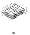
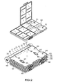
- the flat accessories boxes 12;22;32 have different sizes, i.e., a tray 10;20;30 can carry one big-size flat accessories box 12 (see FIG. 2), two medium-size flat accessories boxes 22 (see FIG. 7), or four small-size flat accessories boxes 32 (see FIG. 8).
- each tray 10;20;30 has at least two locating blocks 50 upwardly disposed at the top and arranged at right angles; each flat accessories box 12;22;32 has a plurality of recessed bottom locating holes 51 corresponding to the locating blocks 50 at the tray 10;20;30 . Because the trays 10;20;30 and the flat accessories boxes 12;22;32 are molded from plastics, the locating blocks 50 are springy, and the recessed bottom locating holes 51 are slightly expansible.
- the respective locating blocks 50 are respectively press-fitted into the respective recessed bottom locating holes 51 , thereby causing the flat accessories boxes 12;22;32 to be respectively firmly secured to the trays 10;20;30 .
- the friction force between the respective flat accessories boxes 12;22;32 and the respective trays 10;20;30 is sufficient to firmly secure the into the respective recessed bottom locating holes 51 , thereby causing the flat accessories boxes 12;22;32 to the trays 10;20;30 , and the flat accessories boxes 12;22;32 do not fall from the trays 10;20;30 when turning the trays 10;20;30 about the pivot shaft 40 .
- each tray 10;20;30 has two oval through holes 13;23;33 symmetrically disposed near two opposite lateral sides.
- the user can insert a finger through the oval through holes 13;23;33 to push the flat accessories boxes 12;22;32 upwardly away from the trays 10;20;30 in direction reversed to the bonding direction between the locating blocks 50 and the recessed bottom locating holes 51 . Therefore, the recessed bottom locating holes 51 can be smoothly disengaged from the locating blocks 50 without damaging the locating blocks 50 .
- the tray 20 carrying two medium-size flat accessories boxes 22 is seen after opening of the tray 10 carrying one big-size flat accessories box 12 from the other trays.
- the medium-size flat accessories boxes 22 are about one half of the size of one big-size flat accessories box 12 .
- Every medium-size flat accessories box 22 has a plurality of bottom locating holes 51 disposed adjacent to three of the four sides thereof and connected to corresponding locating blocks 50 at the tray 20 .
- the tray 30 carrying four small-size flat accessories boxes 32 is seen after opening of the tray 10 carrying one big-size flat accessories box 12 with the tray 20 carrying two medium-size flat accessories boxes 22 .
- the small-size flat accessories boxes 32 are about one half of the size of one medium-size flat accessories box 22 .
- Every small-size flat accessories box 32 has a plurality of recessed bottom locating holes 51 disposed adjacent to two of the four sides thereof and connected to corresponding locating blocks 50 at the tray 30 .
- one medium-size flat accessories box 22 and two small-size flat accessories boxes 32 can be carried in one tray 20 .
- the flat accessories boxes 12;22;32 can detachably and selectively set in the trays 10;20;30 .
- FIGS. 1 ⁇ 9 A prototype of storage rack has been constructed with the features of the annexed drawings of FIGS. 1 ⁇ 9.
- the storage rack functions smoothly to provide all of the features discussed earlier.
Abstract
Description
- The present invention relates to storage racks according to the preamble of
claims 1 and 5; - Such a storage rack is know from
EP 1364753A1 - Various storage boxes are known for keeping accessories and small items. These storage boxes commonly comprise a box body defining a plurality of compartments for keeping different accessories, and a cover hinged to the box body. Several storage boxes may be joined, forming a storage rack.
- There is known a loose-leaf type storage rack, which comprises a pivot shaft, a plurality of trays, and a plurality of flat accessories boxes mounted in the trays. The trays each have a plurality of knuckles respectively pivotally coupled to the pivot shaft such that the trays are arranged in a stack and can be turned about the pivot shaft together or respectively relative to one another. Positioning structure (not shown) is provided between the pivot shaft and the knuckles such that the trays can be respectively positioned in the desired angular position after having been turned about the pivot shaft. This design of loose-leaf type storage rack is functional. However, because the flat accessories boxes are available in only one single size, the user cannot arrange different sizes of flat accessories boxes in the trays to provide different combinations.
- Moreover with this type of storage rack, shown in
EP-A-1364753 , there is little press-fit or other positive engagement between said trays, constituting carrier frames, and said flat accessories boxes, constituting box bodies, which box bodies are thus easily detachable from the carrier frames. - The above-mentioned problem is solved by a storage rack according to Claim 1 and also by a storage rack according to
Claim 5. Further advantages of the invention are disclosed by the dependent Claims 2 to 4 and 6 to 8. -
- FIG. 1 is an elevational view of a storage rack according to the present invention.
- FIG. 2 is an exploded view of the storage rack according to the present invention.
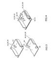
- FIG. 3 is an exploded view in an enlarged scale of a part of the present invention.
- FIG. 4 is an assembly view of FIG. 3.
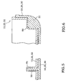
- FIG. 5 is a sectional view taken along line 5-5 of FIG. 4.
- FIG. 6 is a sectional view taken along line 6-6 of FIG. 4.
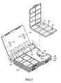
- FIG. 7 is another exploded view of the storage rack according to the present invention.
- FIG. 8 is still another exploded view of the storage rack according to the present invention.
- FIG. 9 is still another exploded view of the storage rack according to the present invention.
- Referring to FIG. 1, a storage rack is shown comprising a
pivot shaft 40, a plurality oftrays 10;20;30, and a plurality offlat accessories boxes 12;22;32 mounted in thetrays 10;20;30. Thetrays 10;20;30 each have a plurality ofknuckles 11;21;31 respectively pivotally coupled to thepivot shaft 40 such that thetrays 10;20;30 are arranged in a stack and can be turned about thepivot shaft 40 together or respectively relative to one another. Positioning structure (not shown) is provided between thepivot shaft 40 and theknuckles 11;21;31 such that thetrays 10;20;30 can be respectively positioned in the desired angular position after having been turned about thepivot shaft 40. Theflat accessories boxes 12;22;32 have different sizes, i.e., atray 10;20;30 can carry one big-size flat accessories box 12 (see FIG. 2), two medium-size flat accessories boxes 22 (see FIG. 7), or four small-size flat accessories boxes 32 (see FIG. 8). - Referring to FGS. 2~6, each
tray 10;20;30 has at least two locatingblocks 50 upwardly disposed at the top and arranged at right angles; eachflat accessories box 12;22;32 has a plurality of recessedbottom locating holes 51 corresponding to the locatingblocks 50 at thetray 10;20;30. Because thetrays 10;20;30 and theflat accessories boxes 12;22;32 are molded from plastics, the locatingblocks 50 are springy, and the recessedbottom locating holes 51 are slightly expansible. When put theflat accessories boxes 12;22;32 in thetrays 10;20;30, the respective locatingblocks 50 are respectively press-fitted into the respective recessedbottom locating holes 51, thereby causing theflat accessories boxes 12;22;32 to be respectively firmly secured to thetrays 10;20;30. The friction force between the respectiveflat accessories boxes 12;22;32 and therespective trays 10;20;30 is sufficient to firmly secure the into the respective recessedbottom locating holes 51, thereby causing theflat accessories boxes 12;22;32 to thetrays 10;20;30, and theflat accessories boxes 12;22;32 do not fall from thetrays 10;20;30 when turning thetrays 10;20;30 about thepivot shaft 40. - Referring to FIGS. 2, 7, and 8, each
tray 10;20;30 has two oval throughholes 13;23;33 symmetrically disposed near two opposite lateral sides. The user can insert a finger through the oval throughholes 13;23;33 to push theflat accessories boxes 12;22;32 upwardly away from thetrays 10;20;30 in direction reversed to the bonding direction between the locatingblocks 50 and the recessed bottom locatingholes 51. Therefore, the recessedbottom locating holes 51 can be smoothly disengaged from the locatingblocks 50 without damaging the locatingblocks 50. - Referring to FIG. 7, the
tray 20 carrying two medium-sizeflat accessories boxes 22 is seen after opening of thetray 10 carrying one big-sizeflat accessories box 12 from the other trays. The medium-sizeflat accessories boxes 22 are about one half of the size of one big-sizeflat accessories box 12. Every medium-sizeflat accessories box 22 has a plurality ofbottom locating holes 51 disposed adjacent to three of the four sides thereof and connected to corresponding locatingblocks 50 at thetray 20. - Referring to FIG. 8, the
tray 30 carrying four small-sizeflat accessories boxes 32 is seen after opening of thetray 10 carrying one big-sizeflat accessories box 12 with thetray 20 carrying two medium-sizeflat accessories boxes 22. The small-sizeflat accessories boxes 32 are about one half of the size of one medium-sizeflat accessories box 22. Every small-sizeflat accessories box 32 has a plurality of recessedbottom locating holes 51 disposed adjacent to two of the four sides thereof and connected to corresponding locatingblocks 50 at thetray 30. - Referring to FIG. 9, one medium-size
flat accessories box 22 and two small-sizeflat accessories boxes 32 can be carried in onetray 20. By means of the recessedbottom locating holes 51 at theflat accessories boxes 12;22; 32 and the locatingblocks 50 at thetrays 10;20;30, theflat accessories boxes 12;22;32 can detachably and selectively set in thetrays 10;20;30. - A prototype of storage rack has been constructed with the features of the annexed drawings of FIGS. 1~9. The storage rack functions smoothly to provide all of the features discussed earlier.
Claims (8)
- A storage rack comprising a pivot shaft (40), a plurality of trays (10; 20; 30) molded from plastics and respectively pivoted to said pivot shaft (40), a plurality of flat accessories boxes (12; 22; 32) molded from plastics and respectively detachably carried in said trays (10; 20; 30); a positioning structure adapted to secure said flat accessories boxes (12; 22; 32) to said trays (10; 20; 30), characterised by said positioning structure comprising a plurality of recessed locating holes (51) disposed at a bottom side of each of said flat accessories boxes (12; 22; 32), and a plurality of locating blocks (50) provided at a top side of each of said trays ( 10; 20; 30) and adapted to engage said recessed locating holes (51), and by said trays (10; 20; 30) each having a plurality of through holes (13; 23; 33) symmetrically disposed near two opposite lateral sides thereof for the insertion of the user's finger to push said flat accessories boxes (12; 22; 32) away from said trays.
- A storage rack as claimed in Claim 1 wherein the number of recessed locating holes (51) at each said flat accessories box (12; 22; 32) is equal to the number of the locating blocks (50) at each said tray (10; 20; 30).
- A storage rack as claimed in Claim 1 or Claim 2, wherein said recessed locating holes (51) are respectively arranged along three of four sides of each said flat accessories box (12; 22; 32) and coupled to corresponding locating blocks (50) at said trays (10; 20; 30).
- A storage rack as claimed in Claim 1 or Claim 2, wherein said recessed locating holes (51) are respectively arranged along two adjacent sides of each said flat accessories box (12; 22; 32) and coupled to corresponding locating blocks (50) at said trays (10;20; 30).
- A storage rack comprising a pivot shaft (40), a plurality of trays (10; 20; 30) molded from plastics and respectively pivoted to said pivot shaft (40), a plurality of flat accessories boxes (12; 22; 32) moulded from plastics and respectively detachably carried in said trays (10; 20; 30); a positioning structure adapted to secure said flat accessories boxes (12; 22; 32) to said trays (10; 20; 30), characterised by said positioning structure comprising a plurality of recessed locating holes(51) formed in a bottom side of each said flat accessories box (12; 22; 32), and a plurality of locating blocks (50) respectively formed integral with said trays (10; 20; 30) along each of four peripheral sides of each tray (10; 20; 30) and adapted to engage said recessed locating holes (51), and by said trays (10; 20; 30) each having a plurality of through holes (13; 23; 33) symmetrically disposed near two opposite lateral sides thereof for the insertion of the user's finger to push said flat accessories boxes (12; 22; 32) away from said trays.
- A storage rack as claimed in Claim 5, wherein the number of the recessed locating holes (51) at each said flat accessories box (12; 22; 32) is equal to the number of the locating blocks (50) at each said tray ( 10; 20; 30).
- A storage rack as claimed in Claim 5 or Claim 6, wherein said recessed locating holes (51) are respectively arranged along three or four sides of each said flat accessories box (12; 22; 32) and coupled to corresponding locating blocks (50) at said trays (10; 20; 30).
- A storage rack as claimed in Claim 5 or Claim 6, wherein recessed locating holes (51) are respectively arranged along two adjacent sides of each said flat accessories box (12; 22; 32) and coupled to corresponding locating blocks (50) at said trays (10; 20; 30).
Priority Applications (4)
| Application Number | Priority Date | Filing Date | Title |
|---|---|---|---|
| ES03029819T ES2294238T3 (en) | 2003-12-23 | 2003-12-23 | STORAGE CASE. |
| EP03029819A EP1547730B1 (en) | 2003-12-23 | 2003-12-23 | Storage rack |
| AT03029819T ATE374672T1 (en) | 2003-12-23 | 2003-12-23 | STORAGE RACK |
| DE60316705T DE60316705T2 (en) | 2003-12-23 | 2003-12-23 | storage rack |
Applications Claiming Priority (1)
| Application Number | Priority Date | Filing Date | Title |
|---|---|---|---|
| EP03029819A EP1547730B1 (en) | 2003-12-23 | 2003-12-23 | Storage rack |
Publications (2)
| Publication Number | Publication Date |
|---|---|
| EP1547730A1 EP1547730A1 (en) | 2005-06-29 |
| EP1547730B1 true EP1547730B1 (en) | 2007-10-03 |
Family
ID=34530732
Family Applications (1)
| Application Number | Title | Priority Date | Filing Date |
|---|---|---|---|
| EP03029819A Expired - Lifetime EP1547730B1 (en) | 2003-12-23 | 2003-12-23 | Storage rack |
Country Status (4)
| Country | Link |
|---|---|
| EP (1) | EP1547730B1 (en) |
| AT (1) | ATE374672T1 (en) |
| DE (1) | DE60316705T2 (en) |
| ES (1) | ES2294238T3 (en) |
Cited By (4)
| Publication number | Priority date | Publication date | Assignee | Title |
|---|---|---|---|---|
| CN101193577B (en) * | 2004-10-26 | 2010-05-12 | 钢厂五金器具有限公司 | Device for storing tool |
| CN101325893B (en) * | 2005-10-26 | 2010-12-08 | 钢铁五金器具有限责任公司 | Equipment with bending handle for storing vertical tool |
| CN107054845A (en) * | 2017-02-27 | 2017-08-18 | 王伟鉴 | A kind of multi-functional storage box of legal documents evidence |
| US11884456B2 (en) | 2020-09-25 | 2024-01-30 | Techtronic Cordless Gp | Tool storage system |
Families Citing this family (2)
| Publication number | Priority date | Publication date | Assignee | Title |
|---|---|---|---|---|
| TWI264353B (en) | 2004-10-26 | 2006-10-21 | Global Ind Holdings Ltd | Tool box which can be independent used or layered combination |
| EP1945067B1 (en) * | 2005-10-26 | 2011-01-26 | Steelworks Hardware, L.L.C. | Upright shaft post capable of accommodating various containers |
Family Cites Families (6)
| Publication number | Priority date | Publication date | Assignee | Title |
|---|---|---|---|---|
| CH662487A5 (en) * | 1983-01-03 | 1987-10-15 | Lanter Design Ag | Suitcase-like container and method for its production |
| US4895256A (en) * | 1988-09-23 | 1990-01-23 | Johnston James E | Air conditioning supply carrier |
| DE9205444U1 (en) * | 1992-04-22 | 1992-06-25 | Chen, Kun-Chen, Da Cha Chen, Taichung, Tw | |
| DE29517259U1 (en) * | 1995-10-31 | 1996-01-04 | Chao Li Smeltion Co | Double tool box |
| US6105767A (en) * | 1997-04-11 | 2000-08-22 | Maxtech, Inc. | Tool case with butterfly door |
| US6648390B1 (en) * | 2002-05-21 | 2003-11-18 | Global Industries Holdings Ltd. | Single-stack tool rack |
-
2003
- 2003-12-23 AT AT03029819T patent/ATE374672T1/en not_active IP Right Cessation
- 2003-12-23 ES ES03029819T patent/ES2294238T3/en not_active Expired - Lifetime
- 2003-12-23 EP EP03029819A patent/EP1547730B1/en not_active Expired - Lifetime
- 2003-12-23 DE DE60316705T patent/DE60316705T2/en not_active Expired - Lifetime
Cited By (4)
| Publication number | Priority date | Publication date | Assignee | Title |
|---|---|---|---|---|
| CN101193577B (en) * | 2004-10-26 | 2010-05-12 | 钢厂五金器具有限公司 | Device for storing tool |
| CN101325893B (en) * | 2005-10-26 | 2010-12-08 | 钢铁五金器具有限责任公司 | Equipment with bending handle for storing vertical tool |
| CN107054845A (en) * | 2017-02-27 | 2017-08-18 | 王伟鉴 | A kind of multi-functional storage box of legal documents evidence |
| US11884456B2 (en) | 2020-09-25 | 2024-01-30 | Techtronic Cordless Gp | Tool storage system |
Also Published As
| Publication number | Publication date |
|---|---|
| DE60316705T2 (en) | 2008-07-17 |
| EP1547730A1 (en) | 2005-06-29 |
| DE60316705D1 (en) | 2007-11-15 |
| ES2294238T3 (en) | 2008-04-01 |
| ATE374672T1 (en) | 2007-10-15 |
Similar Documents
| Publication | Publication Date | Title |
|---|---|---|
| US7357268B2 (en) | Storage rack | |
| USD450240S1 (en) | Nested package | |
| USD512636S1 (en) | Container with lid | |
| US5098235A (en) | Bit storage means for drill press | |
| US5560476A (en) | Name card case | |
| US5887715A (en) | Tool case with snap-in modules | |
| US6062385A (en) | Multifunctional tool box | |
| US5699925A (en) | Interlocking stackable container storage system | |
| USD411445S (en) | Holder for blister packs | |
| USD488718S1 (en) | Tray with cover | |
| USD515313S1 (en) | Stackable front entry storage tote | |
| US20080099485A1 (en) | Sortables storage container | |
| USD493617S1 (en) | Hinged lid container | |
| EP1547730B1 (en) | Storage rack | |
| US6170658B1 (en) | Folding data disc holder | |
| EP1276114A2 (en) | System for storing and transporting discs and accessory materials | |
| CA2451537C (en) | Storage rack | |
| US20040149754A1 (en) | Stackable containers | |
| USD490375S1 (en) | Battery storage case | |
| US20030085141A1 (en) | Compartmentalized tool box | |
| USD499550S1 (en) | Stackable carrying case and storage device | |
| US6083579A (en) | Blow molded article | |
| AU2003101040A4 (en) | Storage rack | |
| US20180319541A1 (en) | Modular Configurable Tool Carrier | |
| USD548967S1 (en) | Computer carrying case assembly |
Legal Events
| Date | Code | Title | Description |
|---|---|---|---|
| PUAI | Public reference made under article 153(3) epc to a published international application that has entered the european phase |
Free format text: ORIGINAL CODE: 0009012 |
|
| AK | Designated contracting states |
Kind code of ref document: A1 Designated state(s): AT BE BG CH CY CZ DE DK EE ES FI FR GB GR HU IE IT LI LU MC NL PT RO SE SI SK TR |
|
| AX | Request for extension of the european patent |
Extension state: AL LT LV MK |
|
| 17P | Request for examination filed |
Effective date: 20051027 |
|
| AKX | Designation fees paid |
Designated state(s): AT BE BG CH CY CZ DE DK EE ES FI FR GB GR HU IE IT LI LU MC NL PT RO SE SI SK TR |
|
| GRAP | Despatch of communication of intention to grant a patent |
Free format text: ORIGINAL CODE: EPIDOSNIGR1 |
|
| GRAS | Grant fee paid |
Free format text: ORIGINAL CODE: EPIDOSNIGR3 |
|
| GRAA | (expected) grant |
Free format text: ORIGINAL CODE: 0009210 |
|
| AK | Designated contracting states |
Kind code of ref document: B1 Designated state(s): AT BE BG CH CY CZ DE DK EE ES FI FR GB GR HU IE IT LI LU MC NL PT RO SE SI SK TR |
|
| REG | Reference to a national code |
Ref country code: GB Ref legal event code: FG4D |
|
| REG | Reference to a national code |
Ref country code: CH Ref legal event code: EP |
|
| REG | Reference to a national code |
Ref country code: IE Ref legal event code: FG4D |
|
| REF | Corresponds to: |
Ref document number: 60316705 Country of ref document: DE Date of ref document: 20071115 Kind code of ref document: P |
|
| REG | Reference to a national code |
Ref country code: ES Ref legal event code: FG2A Ref document number: 2294238 Country of ref document: ES Kind code of ref document: T3 |
|
| REG | Reference to a national code |
Ref country code: CH Ref legal event code: PL |
|
| PG25 | Lapsed in a contracting state [announced via postgrant information from national office to epo] |
Ref country code: CH Free format text: LAPSE BECAUSE OF FAILURE TO SUBMIT A TRANSLATION OF THE DESCRIPTION OR TO PAY THE FEE WITHIN THE PRESCRIBED TIME-LIMIT Effective date: 20071003 Ref country code: LI Free format text: LAPSE BECAUSE OF FAILURE TO SUBMIT A TRANSLATION OF THE DESCRIPTION OR TO PAY THE FEE WITHIN THE PRESCRIBED TIME-LIMIT Effective date: 20071003 Ref country code: SE Free format text: LAPSE BECAUSE OF FAILURE TO SUBMIT A TRANSLATION OF THE DESCRIPTION OR TO PAY THE FEE WITHIN THE PRESCRIBED TIME-LIMIT Effective date: 20080103 |
|
| PG25 | Lapsed in a contracting state [announced via postgrant information from national office to epo] |
Ref country code: PT Free format text: LAPSE BECAUSE OF FAILURE TO SUBMIT A TRANSLATION OF THE DESCRIPTION OR TO PAY THE FEE WITHIN THE PRESCRIBED TIME-LIMIT Effective date: 20080303 Ref country code: BG Free format text: LAPSE BECAUSE OF FAILURE TO SUBMIT A TRANSLATION OF THE DESCRIPTION OR TO PAY THE FEE WITHIN THE PRESCRIBED TIME-LIMIT Effective date: 20080103 |
|
| ET | Fr: translation filed | ||
| PG25 | Lapsed in a contracting state [announced via postgrant information from national office to epo] |
Ref country code: AT Free format text: LAPSE BECAUSE OF FAILURE TO SUBMIT A TRANSLATION OF THE DESCRIPTION OR TO PAY THE FEE WITHIN THE PRESCRIBED TIME-LIMIT Effective date: 20071003 |
|
| PG25 | Lapsed in a contracting state [announced via postgrant information from national office to epo] |
Ref country code: MC Free format text: LAPSE BECAUSE OF NON-PAYMENT OF DUE FEES Effective date: 20071231 Ref country code: CZ Free format text: LAPSE BECAUSE OF FAILURE TO SUBMIT A TRANSLATION OF THE DESCRIPTION OR TO PAY THE FEE WITHIN THE PRESCRIBED TIME-LIMIT Effective date: 20071003 Ref country code: DK Free format text: LAPSE BECAUSE OF FAILURE TO SUBMIT A TRANSLATION OF THE DESCRIPTION OR TO PAY THE FEE WITHIN THE PRESCRIBED TIME-LIMIT Effective date: 20071003 |
|
| PLBE | No opposition filed within time limit |
Free format text: ORIGINAL CODE: 0009261 |
|
| STAA | Information on the status of an ep patent application or granted ep patent |
Free format text: STATUS: NO OPPOSITION FILED WITHIN TIME LIMIT |
|
| PG25 | Lapsed in a contracting state [announced via postgrant information from national office to epo] |
Ref country code: BE Free format text: LAPSE BECAUSE OF FAILURE TO SUBMIT A TRANSLATION OF THE DESCRIPTION OR TO PAY THE FEE WITHIN THE PRESCRIBED TIME-LIMIT Effective date: 20071003 Ref country code: RO Free format text: LAPSE BECAUSE OF FAILURE TO SUBMIT A TRANSLATION OF THE DESCRIPTION OR TO PAY THE FEE WITHIN THE PRESCRIBED TIME-LIMIT Effective date: 20071003 Ref country code: SK Free format text: LAPSE BECAUSE OF FAILURE TO SUBMIT A TRANSLATION OF THE DESCRIPTION OR TO PAY THE FEE WITHIN THE PRESCRIBED TIME-LIMIT Effective date: 20071003 |
|
| 26N | No opposition filed |
Effective date: 20080704 |
|
| PG25 | Lapsed in a contracting state [announced via postgrant information from national office to epo] |
Ref country code: IE Free format text: LAPSE BECAUSE OF NON-PAYMENT OF DUE FEES Effective date: 20071224 |
|
| PG25 | Lapsed in a contracting state [announced via postgrant information from national office to epo] |
Ref country code: EE Free format text: LAPSE BECAUSE OF FAILURE TO SUBMIT A TRANSLATION OF THE DESCRIPTION OR TO PAY THE FEE WITHIN THE PRESCRIBED TIME-LIMIT Effective date: 20071003 Ref country code: GR Free format text: LAPSE BECAUSE OF FAILURE TO SUBMIT A TRANSLATION OF THE DESCRIPTION OR TO PAY THE FEE WITHIN THE PRESCRIBED TIME-LIMIT Effective date: 20080104 |
|
| PG25 | Lapsed in a contracting state [announced via postgrant information from national office to epo] |
Ref country code: FI Free format text: LAPSE BECAUSE OF FAILURE TO SUBMIT A TRANSLATION OF THE DESCRIPTION OR TO PAY THE FEE WITHIN THE PRESCRIBED TIME-LIMIT Effective date: 20071003 |
|
| PG25 | Lapsed in a contracting state [announced via postgrant information from national office to epo] |
Ref country code: SI Free format text: LAPSE BECAUSE OF FAILURE TO SUBMIT A TRANSLATION OF THE DESCRIPTION OR TO PAY THE FEE WITHIN THE PRESCRIBED TIME-LIMIT Effective date: 20071003 |
|
| PG25 | Lapsed in a contracting state [announced via postgrant information from national office to epo] |
Ref country code: CY Free format text: LAPSE BECAUSE OF FAILURE TO SUBMIT A TRANSLATION OF THE DESCRIPTION OR TO PAY THE FEE WITHIN THE PRESCRIBED TIME-LIMIT Effective date: 20071003 |
|
| PG25 | Lapsed in a contracting state [announced via postgrant information from national office to epo] |
Ref country code: LU Free format text: LAPSE BECAUSE OF NON-PAYMENT OF DUE FEES Effective date: 20071223 |
|
| PG25 | Lapsed in a contracting state [announced via postgrant information from national office to epo] |
Ref country code: TR Free format text: LAPSE BECAUSE OF FAILURE TO SUBMIT A TRANSLATION OF THE DESCRIPTION OR TO PAY THE FEE WITHIN THE PRESCRIBED TIME-LIMIT Effective date: 20071003 Ref country code: HU Free format text: LAPSE BECAUSE OF FAILURE TO SUBMIT A TRANSLATION OF THE DESCRIPTION OR TO PAY THE FEE WITHIN THE PRESCRIBED TIME-LIMIT Effective date: 20080404 |
|
| PGFP | Annual fee paid to national office [announced via postgrant information from national office to epo] |
Ref country code: ES Payment date: 20111220 Year of fee payment: 9 Ref country code: NL Payment date: 20111220 Year of fee payment: 9 |
|
| REG | Reference to a national code |
Ref country code: NL Ref legal event code: V1 Effective date: 20130701 |
|
| PG25 | Lapsed in a contracting state [announced via postgrant information from national office to epo] |
Ref country code: NL Free format text: LAPSE BECAUSE OF NON-PAYMENT OF DUE FEES Effective date: 20130701 |
|
| REG | Reference to a national code |
Ref country code: ES Ref legal event code: FD2A Effective date: 20140527 |
|
| PG25 | Lapsed in a contracting state [announced via postgrant information from national office to epo] |
Ref country code: ES Free format text: LAPSE BECAUSE OF NON-PAYMENT OF DUE FEES Effective date: 20121224 |
|
| REG | Reference to a national code |
Ref country code: FR Ref legal event code: PLFP Year of fee payment: 13 |
|
| REG | Reference to a national code |
Ref country code: FR Ref legal event code: PLFP Year of fee payment: 14 |
|
| REG | Reference to a national code |
Ref country code: FR Ref legal event code: PLFP Year of fee payment: 15 |
|
| PGFP | Annual fee paid to national office [announced via postgrant information from national office to epo] |
Ref country code: DE Payment date: 20181114 Year of fee payment: 16 |
|
| PGFP | Annual fee paid to national office [announced via postgrant information from national office to epo] |
Ref country code: IT Payment date: 20181212 Year of fee payment: 16 Ref country code: GB Payment date: 20181129 Year of fee payment: 16 Ref country code: FR Payment date: 20181120 Year of fee payment: 16 |
|
| REG | Reference to a national code |
Ref country code: DE Ref legal event code: R119 Ref document number: 60316705 Country of ref document: DE |
|
| GBPC | Gb: european patent ceased through non-payment of renewal fee |
Effective date: 20191223 |
|
| PG25 | Lapsed in a contracting state [announced via postgrant information from national office to epo] |
Ref country code: IT Free format text: LAPSE BECAUSE OF NON-PAYMENT OF DUE FEES Effective date: 20191223 Ref country code: DE Free format text: LAPSE BECAUSE OF NON-PAYMENT OF DUE FEES Effective date: 20200701 Ref country code: FR Free format text: LAPSE BECAUSE OF NON-PAYMENT OF DUE FEES Effective date: 20191231 Ref country code: GB Free format text: LAPSE BECAUSE OF NON-PAYMENT OF DUE FEES Effective date: 20191223 |