EP1547709A2 - Drill Chuck - Google Patents
Drill Chuck Download PDFInfo
- Publication number
- EP1547709A2 EP1547709A2 EP05001895A EP05001895A EP1547709A2 EP 1547709 A2 EP1547709 A2 EP 1547709A2 EP 05001895 A EP05001895 A EP 05001895A EP 05001895 A EP05001895 A EP 05001895A EP 1547709 A2 EP1547709 A2 EP 1547709A2
- Authority
- EP
- European Patent Office
- Prior art keywords
- locking
- clamping sleeve
- chuck
- ring
- spring
- Prior art date
- Legal status (The legal status is an assumption and is not a legal conclusion. Google has not performed a legal analysis and makes no representation as to the accuracy of the status listed.)
- Withdrawn
Links
- 239000002184 metal Substances 0.000 claims abstract description 6
- 238000005553 drilling Methods 0.000 claims description 10
- 210000002105 tongue Anatomy 0.000 claims description 4
- 230000005540 biological transmission Effects 0.000 claims description 3
- 239000000428 dust Substances 0.000 claims description 3
- 230000002787 reinforcement Effects 0.000 claims description 2
- 230000015572 biosynthetic process Effects 0.000 abstract description 4
- 238000006073 displacement reaction Methods 0.000 abstract description 2
- 230000008901 benefit Effects 0.000 description 8
- 230000004888 barrier function Effects 0.000 description 4
- 230000003014 reinforcing effect Effects 0.000 description 4
- 230000000903 blocking effect Effects 0.000 description 2
- 238000013016 damping Methods 0.000 description 2
- 230000000694 effects Effects 0.000 description 2
- 239000000463 material Substances 0.000 description 2
- 230000009286 beneficial effect Effects 0.000 description 1
- 230000002349 favourable effect Effects 0.000 description 1
- 238000001746 injection moulding Methods 0.000 description 1
- 238000003780 insertion Methods 0.000 description 1
- 230000037431 insertion Effects 0.000 description 1
- 238000003754 machining Methods 0.000 description 1
- 238000004519 manufacturing process Methods 0.000 description 1
Images


Classifications
-
- B—PERFORMING OPERATIONS; TRANSPORTING
- B23—MACHINE TOOLS; METAL-WORKING NOT OTHERWISE PROVIDED FOR
- B23B—TURNING; BORING
- B23B31/00—Chucks; Expansion mandrels; Adaptations thereof for remote control
- B23B31/02—Chucks
- B23B31/10—Chucks characterised by the retaining or gripping devices or their immediate operating means
- B23B31/12—Chucks with simultaneously-acting jaws, whether or not also individually adjustable
- B23B31/1207—Chucks with simultaneously-acting jaws, whether or not also individually adjustable moving obliquely to the axis of the chuck in a plane containing this axis
- B23B31/123—Chucks with simultaneously-acting jaws, whether or not also individually adjustable moving obliquely to the axis of the chuck in a plane containing this axis with locking arrangements
-
- B—PERFORMING OPERATIONS; TRANSPORTING
- B23—MACHINE TOOLS; METAL-WORKING NOT OTHERWISE PROVIDED FOR
- B23B—TURNING; BORING
- B23B31/00—Chucks; Expansion mandrels; Adaptations thereof for remote control
- B23B31/02—Chucks
- B23B31/10—Chucks characterised by the retaining or gripping devices or their immediate operating means
- B23B31/12—Chucks with simultaneously-acting jaws, whether or not also individually adjustable
- B23B31/1207—Chucks with simultaneously-acting jaws, whether or not also individually adjustable moving obliquely to the axis of the chuck in a plane containing this axis
- B23B31/1238—Jaws movement actuated by a nut with conical screw-thread
-
- B—PERFORMING OPERATIONS; TRANSPORTING
- B23—MACHINE TOOLS; METAL-WORKING NOT OTHERWISE PROVIDED FOR
- B23B—TURNING; BORING
- B23B2231/00—Details of chucks, toolholder shanks or tool shanks
- B23B2231/28—Dust covers
-
- B—PERFORMING OPERATIONS; TRANSPORTING
- B23—MACHINE TOOLS; METAL-WORKING NOT OTHERWISE PROVIDED FOR
- B23B—TURNING; BORING
- B23B2231/00—Details of chucks, toolholder shanks or tool shanks
- B23B2231/38—Keyless chucks for hand tools
-
- Y—GENERAL TAGGING OF NEW TECHNOLOGICAL DEVELOPMENTS; GENERAL TAGGING OF CROSS-SECTIONAL TECHNOLOGIES SPANNING OVER SEVERAL SECTIONS OF THE IPC; TECHNICAL SUBJECTS COVERED BY FORMER USPC CROSS-REFERENCE ART COLLECTIONS [XRACs] AND DIGESTS
- Y10—TECHNICAL SUBJECTS COVERED BY FORMER USPC
- Y10S—TECHNICAL SUBJECTS COVERED BY FORMER USPC CROSS-REFERENCE ART COLLECTIONS [XRACs] AND DIGESTS
- Y10S279/00—Chucks or sockets
- Y10S279/902—Keyless type socket
-
- Y—GENERAL TAGGING OF NEW TECHNOLOGICAL DEVELOPMENTS; GENERAL TAGGING OF CROSS-SECTIONAL TECHNOLOGIES SPANNING OVER SEVERAL SECTIONS OF THE IPC; TECHNICAL SUBJECTS COVERED BY FORMER USPC CROSS-REFERENCE ART COLLECTIONS [XRACs] AND DIGESTS
- Y10—TECHNICAL SUBJECTS COVERED BY FORMER USPC
- Y10T—TECHNICAL SUBJECTS COVERED BY FORMER US CLASSIFICATION
- Y10T279/00—Chucks or sockets
- Y10T279/17—Socket type
- Y10T279/17615—Obliquely guided reciprocating jaws
- Y10T279/17623—Threaded sleeve and jaw
- Y10T279/17632—Conical sleeve
-
- Y—GENERAL TAGGING OF NEW TECHNOLOGICAL DEVELOPMENTS; GENERAL TAGGING OF CROSS-SECTIONAL TECHNOLOGIES SPANNING OVER SEVERAL SECTIONS OF THE IPC; TECHNICAL SUBJECTS COVERED BY FORMER USPC CROSS-REFERENCE ART COLLECTIONS [XRACs] AND DIGESTS
- Y10—TECHNICAL SUBJECTS COVERED BY FORMER USPC
- Y10T—TECHNICAL SUBJECTS COVERED BY FORMER US CLASSIFICATION
- Y10T279/00—Chucks or sockets
- Y10T279/32—Means to prevent jaw loosening
Definitions
- the invention relates to a keyless drill chuck with a chuck body connectable to a drill spindle, with a receptacle for the drilling tool between them forming jaws, which are inclined to the chuck axis extending guide receptacles for opening and closing of the chuck rotatable by one on the chuck body and axially immovable guided threaded ring adjustable are, and with one of the adjustment of the jaws through Rotation of the threaded ring serving clamping sleeve.
- Such a chuck is known from EP 0 785 041 A1 known, in which the clamping sleeve in two parts with a outer metal coat and an inner, off Plastic-made coat is formed. It serves the outer jacket to, one against damage insensitive and resistant outer surface be provided so that damage in the drilling or by applying a pair of pliers to rotate the clamping sleeve largely avoided while the inner, out Plastic existing coat is intended for Training a control curve to be formed, the Actuation of a rotation of the threaded ring serves preventing or releasing locking device.
- the Forming the control curve is easy by injection molding possible, made with the complicated designs can be.
- This known chuck avoids the Disadvantage, the control curve from inside out by cutting To produce machining, which only under high Material, cost and time would be possible.
- the invention is based on the object, a chuck of the type mentioned above in such a way that its Assembly is simplified.
- the object underlying the invention is in a Drill chuck of the type mentioned solved by a Embodiment, characterized by a rear the threaded ring, the Futtergroper axially forward supported, the axial securing the clamping sleeve serving Hollow disk.
- This chuck according to the invention has the advantage that the clamping sleeve in a simple manner to the chuck body be plugged and secured by the lens can be, so that the axial securing of the clamping sleeve axially rearward region takes place.
- this type of axial securing of the lens also realize a sprung mounting of the clamping sleeve, the one damping when driving the drill spindle occurring and transmitted to the clamping sleeve Vibrations causes what one feels to be pleasant is when the user to clamp or release the tool Grasp the clamping sleeve by hand and hold it in place.
- the desired spring action can also achieve by radially resilient at the lens Tongues are designed to engage in the on Clamping sleeve formed groove.
- the advantages of the drill chuck according to the invention are evident especially clear when the clamping sleeve a control cam for actuating a rotation of the threaded ring having preventing or releasing locking device.
- the axial securing of the clamping sleeve axially rear on Chuck provides a space for easier and easier more variable arrangement of the locking device whose Functions, especially secure locking not through Vibration is at risk due to the spring action be largely damped.
- control cam through webs is formed, from the radially outer side of the Metal existing clamping sleeve projecting inwards.
- This offers the advantage that not inside the clamping sleeve the structures for the formation of the control curve must be worked out, but that the clamping sleeve can be processed from the outside, these being It is deformed so that on the inside of the Cam forms.
- the webs through the Side walls of at least one in the clamping sleeve embossed bag are formed, since the bag is a in is a stable structure that in the usual Stress when adjusting the clamping sleeve not is deformed.
- Control cam is covered by a cap, wherein Conveniently the cap by an axially on Chuck-supported dust cover is formed.
- an embodiment which is characterized characterized in that one in the circumferential direction two Has locking positions having locking device is provided which is the by a locking cam of a detent spring formed locking member in which in the locking recesses indented locking member in the one detent position and at the disengaged locking member in the other detent position located, and that the cam the two Rest stops includes.
- the locking device serves with open chuck the mutual rotational drive of Secure clamping sleeve and intermediate ring and at Exclude closed chuck that is in Bohr stipulate the clamping sleeve automatically against the Intermediate sleeve adjusted and so the locking device actuated.
- the locking device should also make sure that with threaded chuck the threaded ring is taken by the clamping sleeve during rotation, without that the locking member adjusted in the engaged state becomes.
- both locking members can only perform their function, if these are also in contact with the as a spline realized locking recesses arrive, it is expedient if the locking spring with a the alignment the locking members relative to the locking recess enabling game is arranged in the intermediate ring.
- the locking spring with a the alignment the locking members relative to the locking recess enabling game is arranged in the intermediate ring.
- the two locking members at the ends are arranged, if that in the opening the drill chuck corresponding direction of rotation forward Locking member bent in the direction of locking recesses and the other locking member is looped designed for Action on the front locking member matching flank surface.
- the lens on their plan side reinforcing ribs has, and that the Reinforcement ribs in the middle of the waistband segments are arranged. These reinforcing ribs serve to the spring action more accurate to the desired size to vote, in particular the spring action in the axial To modify direction and radial direction.
- a spring action of the lens can be in Particularly simple way also achieve that the Cover disc in two parts with a chuck body associated ring is formed, the one at the Clamping sleeve anchored circlip supports.
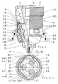
- the chuck shown in the drawing are used for Recording a drill, not shown, and each have a chuck body 1 for connection to one also not shown drilling spindle.
- the chuck body 1 has a threaded receptacle 2 on which connect forward an axial passage 80 can be slid to the strokes of one in the drill spindle guided bat or club directly on the Shank end of the held in a tool holder 4 To transfer drill.
- the chucks have the Drill centering, axially leading and / or chucking Jaws 5, which coaxial in the feed axis 3 Tool holder 4 centric to the chuck axis 3 adjustable are.
- the embodiments show manually tensionable Chuck, in which the jaws 5 in Chuck body 1 out and a jaw toothing. 6 with a tightening thread on a threaded ring 8 in engagement stand.
- the Threaded ring 8 To adjust the jaws 5 is the Threaded ring 8, the axially immovable on the chuck body 1 and rotatably guided and axially rearwardly over a Ball bearing 22, optionally via a pressure ring 21, on Chuck body 1 is supported.
- the a coaxial ring of locking recesses 10 on the Side of the chuck body 1 and on the side of the Threaded rings 8 consists of at least one locking member 12, that under the force of a locking spring in the Barrier recesses 10 engages.
- the locking member 12 can between his to the Barrier recesses 10 in and disengaged states be adjusted, including the locking member 12 by a Control cam 35 on a coaxial, also axially immovable clamping sleeve 9 adjustable and accordingly the clamping sleeve 9 is rotatable relative to the threaded ring 8.
- the control cam 35 is formed by webs 81, of the radially outer side of the existing metal Project the clamping sleeve 9 inwards and through a Bottom plate 82 are connected, in particular by the Side walls of impressed in the clamping sleeve 9 Bags 83 are formed, one in the clamping sleeve. 9 embossed pocket 83 as switching cam 84 for the Locking member 12 acts and thus the circumferential direction the clamping sleeve 9 opposite webs of Bags 83 for actuating the locking device eleventh are provided.
- Lock spring two for simultaneous engagement in the Edge toothing for joint power transmission provided locking members 12 are formed, each of which a pocket 83 is assigned as switching cam 83, wherein the locking spring with a the orientation of Locking members 12 relative to the locking recesses 10th enabling game arranged in an intermediate ring 18 is.
- the two locking members 12 are at the ends of Locking spring arranged, wherein in the opening of the Drill chuck corresponding direction of rotation (arrow 14) in front lying blocking member 12 in the direction of locking recesses 10th is bent and the other locking member 12th looped is designed to act on the front locking member 12 matching flank surface. It is also possible, the two locking members 12th Assign separate locking springs. It is one each own pocket 83 as part of the cam 35 to Adjustment of the locking members 12 provided (Fig. 17, 21:22).
- the rotation of the clamping sleeve 9 relative to the threaded ring. 8 is in both directions of rotation (arrows 14, 15) form-fitting limited to what stops 16 ', 16 "are provided
- Turning the clamping sleeve 9 in the closing of the Drill chuck corresponding direction of rotation (arrow 15) adjusted the locking member 12 from the disengaged State in the engaged state and vice versa, ie by turning the clamping sleeve 9 in the opening of the Drill chuck corresponding direction of rotation (arrow 14) from the engaged state in the disengaged state.
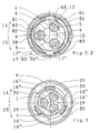
- latching device Between the clamping sleeve 9 and the threaded ring 8 is a provided generally with 17 designated latching device, which has two detent positions in the circumferential direction, wherein in the one detent position the locking member 12 in the on the locking recesses 10 indented state and in the other detent position is in the disengaged state, such as a comparison of the pair of figures 2.1 and 2.2 can be seen.
- the detent positions are due to the intervention of one of the force of a detent spring acted upon locking member 38 " on the side of the threaded ring 8 in accordance with the Clamping sleeve 9 arranged locking receptacles 17 "formed, the Part of the cam 35 and also through in the Clamping sleeve 9 embossed pockets 83 are realized.
- the Locking member 38 " is in particular by a locking cam of Detent spring formed.
- the locking spring and the detent spring are in Figs. 2.1, 2.2, 7, 15 and 16 together of a Spring clip 38 is formed, which is longitudinal in the circumferential direction extends the threaded ring 8 and rotatably with the Threaded ring 8 is connected.
- the spring clip 38 can be provided multiple times (Fig. 17), whereby the Locking device 17 is realized several times. alternative there is also the possibility of one of the locking member 12th with locking spring separate training of Locking device 17, which then also several times and in order to be redundant (FIGS. 18, 20, 22).
- the threaded ring 8 has a guide for the Clamping sleeve 9 forming coaxial intermediate ring 18, the threaded ring parts of the stops 16 ', 16 "for the Clamping sleeve and also the spring clip 38 carries, as well a collar portion 18 'which surrounds the tension thread carrying part of the threaded ring 8 rotatably encloses. It consists of the tensioning thread-bearing part of the Threaded rings 8 divided into two circumferentially, namely initially weakened at each division by a bore and then broken ring halves, which are in an annular groove of the Chuck body 1 against each other and assembled the collar part 18 'held together on the chuck body 1 are.
- the threaded ring 8 also be formed integrally, but in the drawing not shown.
- the threaded ring has 8 or Intermediate ring 18 for radial guidance of the clamping sleeve 9 a circular cylindrical outer surface, which the clamping sleeve 9 with a corresponding circular cylindrical inner surface is present.
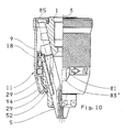
- the in the axial direction undivided trained clamping sleeve 9 axially from the front finished on the chuck body 1 on the chuck body 1 mounted threaded ring 8 are pushed, whereupon the Clamping sleeve 9 in its deferred end position axially is secured.
- the backup of the clamping sleeve 9 against axial displacements occur in the area axially behind the Threaded ring 8 on the chuck body 1 at one with the Chuck body 1 connected lens 85, which also for the radial guidance of the clamping sleeve 9 in the region of her contributes back ring end.
- the Closing disk 85 extending in the circumferential direction, radially resilient tongues 86 formed (Figs.
- FIGS. 9 and 10 for Engaging in a formed on the clamping sleeve 9 groove 87th
- a disc collar 88 integrally formed, the Achieving a radial spring action by collar segments 89th is formed, which is an insertion of the radially allows outer curved ends 90 in the groove 87.
- FIG. 11 shows a between lens 85 and Clamping sleeve 9 formed press fit, to whose Realization of the axially rearward end of the clamping sleeve. 9 is crimped.
- In the lens 85 are still Openings 104 formed adjacent to the Bund segments 89 or the tongues 86 are arranged and the removal of Bohrschmutz serve.
- the End plate further reinforcing ribs 105, the are arranged centrally to the collar segments 89.
- the Fig. 25 and 26 show an embodiment in which the Cover disc (85) in two parts with a Chuck body (1) associated ring is formed, the one on the clamping sleeve (9) anchored retaining ring (106) supported.
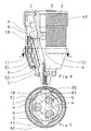
- Axially in front of the clamping sleeve 9 is a free to her rotatable stop ring 50 is provided on the Chuck body 1 axially immovable and rotatably mounted is what the stop ring 50 axially to the rear on a Ring shoulder 51 of the chuck body 1 and axially forward a snap ring 52 is held in an annular groove on Chuck body 1 sits.
- the stop ring 50 protects the Clamping sleeve 9 before, when drilling through a wall to the To hit the wall and thereby be slowed down, what to do could cause the drill chuck to tighten it can only be opened again with difficulty.
- the stop ring 50 also protects the stop ring 50, the clamping sleeve 9 against larger axial load from the front, so that the axial support the clamping sleeve 9 to the rear accordingly low is claimed. Furthermore, the stop ring 50 as Cap 51 or dust cap usable, the Control cam 35 covered.
- the stops 16 ', 16 "for rotation limitation between the Clamping sleeve 9 and the threaded ring 8 are in the Embodiments generally designated 29 Stop pieces and a stop piece 29 receiving Recess 30 is provided, wherein the stop piece 29 at the ends of the rotary path each with one of the Recess 30 in the circumferential direction limiting two End faces 16 ', 16 "comes to the stop Embodiments are each three evenly arranged distributed over the Futtercind Stop pieces 29 and recesses 30 present.
- the stop pieces 29 as wall pieces of Intermediate ring 18 may be formed from the front edge of the intermediate ring 18 axially forward in the on the Wall inside of the clamping sleeve 9 formed Recesses 30 protrude.
- the spring clip 38 forms in the circumferential direction extending spring arm 36, the free end of the arm Has locking member 12. At long stretched Spring arm 36 too soft spring characteristic too avoid is in the chuck of FIG. 14 a through a wave structure 100 formed attenuator 101 realized.
- the spring arm 36 on the control cam 35 in one Distance from the locking member 12, the springs of the Spring arm 35 at the location of the locking member 12 um at least its depth of engagement in the Locking recesses 10 allows, so that when tightening of the lining, the locking member 12 via the wreath of Sperrausappel 10 can slip away.
- On the spring clip 38 are two in the circumferential direction at a mutual distance Provided projections 38 ', 38 ".
- the Locking member 12 disengaged from the locking recesses 10th held; in the locked state it must be on the cam 35th be pressed into the locking recesses 10.
- the locking engagement of the locking member 12 in the Locking recesses 10 are the spring bars 34 of the Spring clip 38 resiliently on the rim of the locking recesses 10 on, so that the spring clip 38 in its position in Intermediate ring 18 automatically adjusted. In this sense also proves to be a spring leg 71, the Spring clip 38 with his the projection 38 "facing away End forms and also under bias the wreath the locking recesses 10 is applied.
- the the chuck body 1 adjacent two spring bars 34 and the spring leg 71st exert a braking effect, by the Bohr concerned occurring vibrations to chuck body 1, Threaded ring 8 or intermediate ring 18 and clamping sleeve 9 be steamed.
- the stops 16 ', 16 ", the locking device 11 and the latching device 17 axially arranged in front of the clamping thread.
- these parts at least some thereof to provide axially behind the clamping thread, wherein
- the body-fixed pressure ring 21 to this offers to be provided with the barrier recesses 10.
- Figs. 1 and 2.1 show the chuck in the unlocked Status.
- the spring arm 36 is adjusted radially outward, so that the locking member 12 outside the Barrier recesses 10 is.
- the in the recess 17 " cross locking projection 38 "secures the intermediate ring 18th and the clamping sleeve 9 against rotation against each other, so that during rotation of the clamping sleeve 9 via the intermediate ring 18th the threaded ring 8 relative to the chuck body 1 freely rotated as long as the drill chuck is open.
- the clamping sleeve 9 held by hand and the Chuck body 1 is rotated by the drill spindle.
- the Clamping sleeve 9 can therefore be moved axially over practically the full length of the chuck to the axial rear Feed end extend while the only one from the outside Make hand accessible feed handle. Only if nevertheless is desired, the chuck body 1, regardless of the To manipulate the drilling spindle, it is recommended that the End plate 85 in the form of a retaining ring 40 for the Form feed body 1, in which case the retaining ring 40th rotatably connected to the chuck body 1 must be connected.
- the clamping sleeve 9 In the manufacture of the clamping sleeve 9 is used to protect whose shape in the hollow clamping sleeve 9 to a plant on Inner circumference of the clamping sleeve 9 coming cylindrical rod introduced and radially from outside to inside the stamp pressed against the clamping sleeve 9, which forms the pocket 83.
- the rod In order to provide as much protection as possible to achieve the original sleeve shape, the rod becomes axial introduced beyond the einzaufrägende bag 83 addition and then only radially until it touches the inner circumference expanded, wherein in the rod recordings are formed, which have the shape of the pockets to be formed 83 and as Die in which the stamp the material of the Forming clamping sleeve 9.
- the rod narrows again and removed from the clamping sleeve 9 become. Since the circumferentially located webs 81 of the Bag 83 can be used for adjustment, it is also possible that the training as in axial Directionally oriented groove 83 'formed pocket 83 of the Stamp is pressed axially against the clamping sleeve 9.
Abstract
Description
Die Erfindung betrifft ein schlüsselloses Bohrfutter mit einem an einer Bohrspindel anschließbaren Futterkörper, mit zwischen sich eine Aufnahme für das Bohrwerkzeug bildenden Spannbacken, die in geneigt zur Futterachse verlaufenden Führungsaufnahmen zum Öffnen und Schließen des Bohrfutters durch einen am Futterkörper drehbar und axial unverschiebbar geführten Gewindering verstellbar sind, und mit einer der Verstellung der Spannbacken durch Verdrehung des Gewinderings dienenden Spannhülse.The invention relates to a keyless drill chuck with a chuck body connectable to a drill spindle, with a receptacle for the drilling tool between them forming jaws, which are inclined to the chuck axis extending guide receptacles for opening and closing of the chuck rotatable by one on the chuck body and axially immovable guided threaded ring adjustable are, and with one of the adjustment of the jaws through Rotation of the threaded ring serving clamping sleeve.
Ein derartiges Bohrfutter ist aus der EP 0 785 041 A1 bekannt, bei dem die Spannhülse zweiteilig mit einem äußeren metallenen Mantel und einem inneren, aus Kunststoff gefertigten Mantel gebildet ist. Dabei dient der äußere Mantel dazu, eine gegen Beschädigungen unempfindliche und widerstandsfähige Außenfläche bereitzustellen, so daß Beschädigungen im Bohrbetrieb oder durch Ansetzen einer Zange zum Drehen der Spannhülse weitgehend vermieden werden, während der innere, aus Kunststoff bestehende Mantel dazu vorgesehen ist, zur Ausbildung einer Steuerkurve geformt zu werden, die der Betätigung einer die Verdrehung des Gewinderinges verhindernden bzw freigebenden Sperreinrichtung dient. Die Formung der Steuerkurve ist im Spritzgußverfahren leicht möglich, mit dem auch komplizierte Gestaltungen gefertigt werden können. Dieses bekannte Bohrfutter vermeidet den Nachteil, die Steuerkurve von innen heraus durch spanende Bearbeitung herstellen zu müssen, was nur unter hohen Material-, Kosten- und Zeitaufwand möglich wäre.Such a chuck is known from EP 0 785 041 A1 known, in which the clamping sleeve in two parts with a outer metal coat and an inner, off Plastic-made coat is formed. It serves the outer jacket to, one against damage insensitive and resistant outer surface be provided so that damage in the drilling or by applying a pair of pliers to rotate the clamping sleeve largely avoided while the inner, out Plastic existing coat is intended for Training a control curve to be formed, the Actuation of a rotation of the threaded ring serves preventing or releasing locking device. The Forming the control curve is easy by injection molding possible, made with the complicated designs can be. This known chuck avoids the Disadvantage, the control curve from inside out by cutting To produce machining, which only under high Material, cost and time would be possible.
Der Erfindung liegt die Aufgabe zugrunde, ein Bohrfutter der eingangs genannten Art so auszubilden, daß dessen Montage vereinfacht ist.The invention is based on the object, a chuck of the type mentioned above in such a way that its Assembly is simplified.
Die der Erfindung zugrunde liegende Aufgabe wird bei einem Bohrfutter der eingangs genannten Art gelöst durch eine Ausführungsform, die gekennzeichnet ist durch eine hinter dem Gewindering angeordnet, am Futterköper axial nach vorn gestützte, der axialen Sicherung der Spannhülse dienenden Hohlscheibe.The object underlying the invention is in a Drill chuck of the type mentioned solved by a Embodiment, characterized by a rear the threaded ring, the Futterköper axially forward supported, the axial securing the clamping sleeve serving Hollow disk.
Dieses erfindungsgemäße Bohrfutter bietet den Vorteil, daß die Spannhülse in einfacher Weise auf den Futterkörper aufgesteckt werden und durch die Abschlußscheibe gesichert werden kann, so daß die axiale Sicherung der Spannhülse an axial rückwärtigen Bereich erfolgt. Zusätzlich läßt sich durch diese Art der axialen Sicherung der Abschlußscheibe auch eine gefederte Lagerung der Spannhülse realisieren, die eine Dämpfung der beim Antreiben der Bohrspindel auftretenden und auf die Spannhülse übertragenen Vibrationen bewirkt, was zum eine als angenehm empfunden wird, wenn der Nutzer zum Spannen bzw Lösen des Werkzeugs die Spannhülse mit der Hand ergreift und festhält. Darüber hinaus treten auch Vorteile im Bohrbetrieb auf, da eine Zentrierung der Spannhülse bewirkt wird. Schließlich ist es auch günstig, daß bei der motorischen Verstellung der Spannbacken in ihre rückwärtige Extremposition einer Klemmung der Spannbacken mit ihren Zahnreihen in dem Gewinde des Gewinderinges entgegengewirkt wird, da der mit der Spannhülse verbundene Gewindering gleichfalls von der Federwirkung profitiert. Für eine möglichst einfache Montage ist es vorteilhaft, wenn die Abschlußscheibe im Bereich des rückwärtigen Ringendes der Spannhülse in eine an der Spannhülse ausgebildeten Nut eingreift.This chuck according to the invention has the advantage that the clamping sleeve in a simple manner to the chuck body be plugged and secured by the lens can be, so that the axial securing of the clamping sleeve axially rearward region takes place. In addition can be by this type of axial securing of the lens also realize a sprung mounting of the clamping sleeve, the one damping when driving the drill spindle occurring and transmitted to the clamping sleeve Vibrations causes what one feels to be pleasant is when the user to clamp or release the tool Grasp the clamping sleeve by hand and hold it in place. About that In addition, there are advantages in drilling operation, as a Centering of the clamping sleeve is effected. Finally is it is also beneficial that in the motor adjustment of Clamping jaws in their rear extreme position of a Clamping the jaws with their rows of teeth in the Thread of the threaded ring is counteracted, since the with the clamping sleeve connected threaded ring also from the Spring effect benefits. For the simplest possible Mounting it is advantageous if the lens in the Area of the rear ring end of the clamping sleeve in a engages on the clamping sleeve formed groove.
Weitere Gestaltungsmöglichkeiten und Vorteile ergeben sich aus den Merkmalen der Unteransprüche.Further design options and advantages arise from the features of the subclaims.
Alternativ läßt sich die gewünschte Federwirkung auch erzielen, indem an der Abschlußscheibe radial federnde Zungen ausgebildet sind zum Eingriff in die an der Spannhülse ausgebildeten Nut.Alternatively, the desired spring action can also achieve by radially resilient at the lens Tongues are designed to engage in the on Clamping sleeve formed groove.
Vorteile für einen störungsfreien Bohrbetrieb und eine lange Lebensdauer des Bohrfutter bieten sich, wenn in der Abschlußscheibe Öffnungen ausgebildet sind. Diese Öffnungen ermöglichen den Austritt von beim Bohrbetrieb auftretenden Bohrstaub, der beim Verbleib im Inneren den Verschleiß erhöhen würde. Advantages for a trouble-free drilling operation and a long life of the chuck are offered when in the End plate openings are formed. These Openings allow the escape of drilling operations occurring Bohrdaub, the remaining in the interior of the Would increase wear.
Die Vorteile des erfindungsgemäßen Bohrfutters zeigen sich besonders deutlich, wenn die Spannhülse eine Steuerkurve zur Betätigung einer die Verdrehung des Gewinderinges verhindernden bzw freigebenden Sperreinrichtung aufweist. Die axiale Sicherung der Spannhülse axial hinten am Bohrfutter schafft einen Freiraum zur einfacheren und variableren Anordnung der Sperreinrichtung, deren Funktionen, insbesondere sichere Verriegelung nicht durch Vibrationen gefährdet ist, die aufgrund der Federwirkung weitgehend gedämpft werden.The advantages of the drill chuck according to the invention are evident especially clear when the clamping sleeve a control cam for actuating a rotation of the threaded ring having preventing or releasing locking device. The axial securing of the clamping sleeve axially rear on Chuck provides a space for easier and easier more variable arrangement of the locking device whose Functions, especially secure locking not through Vibration is at risk due to the spring action be largely damped.
Es ist vorgesehen, daß die Steuerkurve durch Stege gebildet ist, die von der radial äußeren Seite der aus Metall bestehenden Spannhülse nach innen vorstehen. Dies bietet den Vorteil, daß nicht im Inneren der Spannhülse die Strukturen zur Bildung der Steuerkurve herausgearbeitet werden müssen, sondern daß die Spannhülse von der Außenseite aus bearbeitet werden kann, wobei diese dabei so verformt wird, daß sich auf der Innenseite die Steuerkurve ausbildet.It is envisaged that the control cam through webs is formed, from the radially outer side of the Metal existing clamping sleeve projecting inwards. This offers the advantage that not inside the clamping sleeve the structures for the formation of the control curve must be worked out, but that the clamping sleeve can be processed from the outside, these being It is deformed so that on the inside of the Cam forms.
Dabei ist besonders bevorzugt, wenn die Stege durch die Seitenwände mindestens einer in die Spannhülse eingeprägten Tasche gebildet sind, da die Tasche ein in sich stabiles Gebilde darstellt, das bei der üblichen Beanspruchung bei Verstellung der Spannhülse nicht deformiert wird.It is particularly preferred if the webs through the Side walls of at least one in the clamping sleeve embossed bag are formed, since the bag is a in is a stable structure that in the usual Stress when adjusting the clamping sleeve not is deformed.
Günstig ist es weiterhin, wenn die in Umfangsrichtung der Spannhülse einander gegenüberliegenden Stege der Taschen zur Betätigung der Sperreinrichtung vorgesehen sind, da so die zur Verstellung der Spannbacken notwendige Drehbewegung genutzt werden kann, um die Sperreinrichtung zu betätigen. Dabei können über den Umfang der Spannhülse verteilt mehrere Taschen vorgesehen sein, die dann auch dazu genutzt werden können, eine Fingerkuppe in diese einzulegen, um so beim Verdrehen der Spannhülse ein großes Drehmoment erzeugen zu können.It is also favorable if the in the circumferential direction of Clamping sleeve opposite webs of the pockets are provided for actuating the locking device, as so the necessary for adjusting the jaws Rotational motion can be used to lock the device to press. It can over the circumference of the clamping sleeve distributed several pockets may be provided, which then too can be used to put a fingertip in this to insert, so as to turn the clamping sleeve a large To generate torque.
Alternativ besteht auch die Möglichkeit, daß die Steuerkurve durch eine Kappe überdeckt ist, wobei zweckmäßigerweise die Kappe durch eine axial am Futterkörper abgestützte Staubschutzkappe gebildet ist.Alternatively, there is also the possibility that the Control cam is covered by a cap, wherein Conveniently the cap by an axially on Chuck-supported dust cover is formed.
Um ein sicheres Funktionieren der Sperreinrichtung zu gewährleisten, ist weiterhin vorgesehen, daß die Sperreinrichtung aus einem koaxialen Kranz von Sperrausnehmungen und aus mindestens einem Sperrglied besteht, das unter der Kraft einer Sperrfeder durch die Steuerkurve in die Sperrausnehmungen einrückbar ist, wobei das Sperrglied und die Sperrausnehmungen einander in derart geneigten Flankenflächen anliegen, daß diese den Gewindering in der dem Öffnen des Bohrfutters entsprechenden Drehrichtung gegen Verdrehen sperren und beim Verdrehen in der anderen Drehrichtung das Sperrglied gegen die Kraft der Sperrfeder aus den Sperrausnehmungen herausdrücken, und daß durch eine der in die Spannhülse eingeprägten Taschen ein Schaltnocken zur Federspannung gegeben ist. Vorteilhaft ist dabei, wenn der Gewindering drehfest mit einem koaxialen Zwischenring verbunden ist, der die Sperrfeder und das Sperrglied trägt, und wenn der Zwischenring durch Anschläge begrenzt relativ zur Spannhülse verdrehbar ist. To ensure the safe functioning of the locking device continue to be provided for Locking device of a coaxial wreath of Sperrausnehmungen and at least one locking member exists under the force of a locking spring through the Control cam is engageable in the locking recesses, wherein the locking member and the locking recesses each other in abut such inclined flank surfaces that this Threaded ring in the opening of the drill chuck lock the corresponding direction of rotation against rotation and when turning in the other direction of rotation of the locking member against the force of the locking spring from the locking recesses push out, and that through one of the clamping sleeve embossed pockets a switching cam for spring tension given is. It is advantageous if the threaded ring rotatably connected to a coaxial intermediate ring, which carries the locking spring and the locking member, and when the Intermediate ring limited by stops relative to Clamping sleeve is rotatable.
Bevorzugt ist weiterhin eine Ausführungsform, die dadurch gekennzeichnet ist, daß eine in Umfangsrichtung zwei Raststellungen aufweisende Rasteinrichtung vorgesehen ist, wobei sich das durch einen Rastnocken einer Rastfeder gebildete Rastglied bei dem in die Sperrausnehmungen eingerückten Sperrglied in der einen Raststellung und bei dem ausgerückten Sperrglied in der anderen Raststellung befindet, und daß die Steuerkurve die beiden Raststellungen beinhaltet. Die Rasteinrichtung dient dazu, bei offenem Bohrfutter die gegenseitige Drehmitnahme von Spannhülse und Zwischenring zu sichern und bei geschlossenem Bohrfutter auszuschließen, daß sich im Bohrbetrieb die Spannhülse selbsttätig gegenüber der Zwischenhülse verstellt und so die Sperreinrichtung betätigt. Insbesondere soll die Rasteinrichtung auch sicher stellen, daß bei offenem Bohrfutter der Gewindering von der Spannhülse beim Verdrehen mitgenommen wird, ohne daß das Sperrglied in den eingerückten Zustand verstellt wird.Also preferred is an embodiment which is characterized characterized in that one in the circumferential direction two Has locking positions having locking device is provided which is the by a locking cam of a detent spring formed locking member in which in the locking recesses indented locking member in the one detent position and at the disengaged locking member in the other detent position located, and that the cam the two Rest stops includes. The locking device serves with open chuck the mutual rotational drive of Secure clamping sleeve and intermediate ring and at Exclude closed chuck that is in Bohrbetrieb the clamping sleeve automatically against the Intermediate sleeve adjusted and so the locking device actuated. In particular, the locking device should also make sure that with threaded chuck the threaded ring is taken by the clamping sleeve during rotation, without that the locking member adjusted in the engaged state becomes.
Da die aus Metall gefertigte Spannhülse eine gegenüber aus Kunststoff bestehenden Spannhülsen eine größere Masse aufweist und bei modernen Bohrmaschinen als Sicherheitseinrichtung eine Spindelstop-Funktion realisiert ist, wird die Sperreinrichtung stärker belastet. Um deren Funktioniere sicherzustellen, ist vorgesehen, daß an der Sperrfeder zwei zum simultanen Eingriff in die Sperrausnehmungen zur gemeinsamen Kraftübertragung vorgesehenen Sperrglieder ausgebildet sind, denen jeweils eine Tasche als Schaltnocken zugeordnet ist. Since the made of metal clamping sleeve opposite one Plastic existing clamping sleeves a greater mass and in modern drills as Safety device a spindle stop function is realized, the locking device is stronger loaded. To ensure their functioning is provided that on the locking spring two for simultaneous Intervention in the Sperrausnehmungen to the common Power transmission provided locking members formed are each a pocket as a switching cam assigned.
Weil beide Sperrglieder ihre Funktion nur ausüben können, wenn diese auch in Kontakt zu den als Randverzahnung realisierten Sperrausnehmungen gelangen, ist es zweckmäßig, wenn die Sperrfeder mit einem die Ausrichtung der Sperrglieder gegenüber der Sperrausnehmung ermöglichenden Spiel im Zwischenring angeordnet ist. Alternativ besteht naturgemäß die Möglichkeit, die Elastizität der Feder selber auszunutzen, um ein simultanes Anliegen der Sperrglieder an der Randverzahnung zu erreichen.Because both locking members can only perform their function, if these are also in contact with the as a spline realized locking recesses arrive, it is expedient if the locking spring with a the alignment the locking members relative to the locking recess enabling game is arranged in the intermediate ring. Alternatively, of course, there is the possibility that Take advantage of the elasticity of the spring itself to a Simultaneous concern of the locking members on the edge toothing to reach.
Hinsichtlich einer hohen Belastbarkeit der Sperrfeder ist es zweckmäßig, wenn die beiden Sperrglieder an den Enden der Sperrfeder angeordnet sind, wenn das in der dem Öffnen des Bohrfutter entsprechenden Drehrichtung vorn liegende Sperrglied in Richtung Sperrausnehmungen abgekröpft und das andere Sperrglied schleifenförmig gestaltet ist zur Einwirkung auf die zum vorderen Sperrglied übereinstimmende Flankenfläche.With regard to a high load capacity of the locking spring it is expedient if the two locking members at the ends the locking spring are arranged, if that in the opening the drill chuck corresponding direction of rotation forward Locking member bent in the direction of locking recesses and the other locking member is looped designed for Action on the front locking member matching flank surface.
Vorgesehen ist weiterhin, daß die Abschlußscheibe auf ihrer Planseite Verstärkungrippen aufweist, und daß die Verstärkungsrippen mittig innerhalb der Bundsegmente angeordnet sind. Diese Verstärkungsripppen dienen dazu, die Federwirkung genauer auf die gewünschte Größe abzustimmen, insbesondere die Federwirkung in axialer Richtung und radialer Richtung zu modifizieren.It is further provided that the lens on their plan side reinforcing ribs has, and that the Reinforcement ribs in the middle of the waistband segments are arranged. These reinforcing ribs serve to the spring action more accurate to the desired size to vote, in particular the spring action in the axial To modify direction and radial direction.
Eine Federwirkung der Abschlußscheibe läßt sich in besonders einfacher Weise auch dadurch erreichen, daß die Abschlußscheibe zweiteilig mit einem dem Futterkörper zugeordneten Ring gebildet ist, der einen an der Spannhülse verankerten Sicherungsring abstützt. A spring action of the lens can be in Particularly simple way also achieve that the Cover disc in two parts with a chuck body associated ring is formed, the one at the Clamping sleeve anchored circlip supports.
Im folgenden soll die Erfindung an in der Zeichnung dargestellten Ausführungsbeispiele näher erläutert werden; es zeigen:
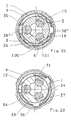
- Fig. 1
- ein Bohrfutter links in einem Axialschnitt, rechts in einer Seitenansicht, jeweils in der Stellung der Spannbacken bei geringstem Spanndurchmesser und im ungesperrten Futterzustand,
- Fig. 2
- den Schnitt II - II aus Fig. 1, und zwar in der Teilfig. 2.1 im ungesperrten, in der Teilfig. 2.2 im gesperrten Futterzustand,
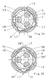
- Fig. 3
- den Schnitt III - III aus Fig. 1,
- Fig. 4
- eine der Fig. 2.1 entsprechende Darstellung einer weiteren Ausführungsform,
- Fig. 5
- eine der Fig. 1 entsprechende Darstellung einer weiteren Ausführungsform,
- Fig. 6
- eine der Fig. 1 entsprechende Darstellung eines Bohrfutters mit einer axial rückwärtig hinter dem Gewindering angeordneten Abschlußscheibe der Spannhülse sowie mit einer Griffhülse,
- Fig. 7
- die Darstellung einer Ausführungsform mit der dem Druckring zugeordneten Sperrverzahnung,
- Fig. 8
- den Schnitt VIII - VIII aus Fig. 1,
- Fig. 9
- eine der Fig. 1 entsprechende Darstellung einer Ausführungsform mit bis zum axial rückwärtigem Ende des Futterkörpers reichender Spannhülse,
- Fig.10
- den Schnitt X - X aus Fig. 9,
- Fig.11
- eine der Fig. 1 entsprechende Darstellung einer Ausführungsform mit der gegenüber der Abschlußscheibe eingebördelter Spannhülse,
- Fig.12
- eine nochmals andere Ausführungsform zur axialen Sicherung der Spannhülse am axial rückwärtige Ende des Futterkörpers,
- Fig.13
- den Schnitt XIII - XVIII aus Fig. 12,
- Fig.14
- eine der Fig. 2.2 entsprechende Darstellung einer Ausführungsform mit einer Sperrfeder erhöhter Dämpfung,
- Fig.15
- eine der Fig. 2.2 entsprechende Darstellung mit
einer
modifizierten Sperrfeder mit 2 Schaltnoppen, - Fig.16
- eine Fig. 14 entsprechende Darstellung einer
Sperrfeder mit 2Rastgliedern und 2 Schaltnoppen, - Fig.17
- eine Fig. 15
entsprechende Darstellung mit 2 Sperrfedern, - Fig.18
- eine Fig. 15 entsprechende Darstellung mit einer das Sperrglied und einer das Rastglied tragenden Feder,
- Fig.19
- eine zu Fig. 18 alternative Ausführungsform,
- Fig.20
- eine zu Fig. 18
alternative Ausführungsform mit 3 Feder, - Fig.21
- eine zu Fig. 20 alternative Ausführungsform,
- Fig.22
- eine zu Fig. 20
alternative Ausführungsform mit 4 Federn, - Fig. 23
- eine der Fig. 1 entsprechende Darstellung mit einer Verstärkungsrippen aufweisenden Abschlußscheibe,
- Fig. 24
- eine Draufsicht auf das Bohrfutter aus Fig. 23.
- Fig. 25
- eine der Fig. 1 entsprechende Darstellung mit einer zweiteiligen Abschlußscheibe, und
- Fig. 26
- eine Draufsicht auf das Bohrfutter aus Fig. 25.
- Fig. 1
- a chuck left in an axial section, right in a side view, in each case in the position of the jaws at the lowest clamping diameter and in the unlocked feed state,
- Fig. 2
- the section II - II of Fig. 1, in the Teilfig. 2.1 in the unlocked, in the Teilfig. 2.2 in the locked feed state,
- Fig. 3
- the section III - III of Fig. 1,
- Fig. 4
- 1 corresponding to FIG. 2.1 representation of another embodiment,
- Fig. 5
- 1 corresponding representation of another embodiment,
- Fig. 6
- 1 corresponding representation of a chuck with an axially rearwardly behind the threaded ring arranged closure disc of the clamping sleeve and with a grip sleeve,
- Fig. 7
- the representation of an embodiment with the pressure ring associated with the locking teeth,
- Fig. 8
- the section VIII - VIII of Fig. 1,
- Fig. 9
- 1 corresponding representation of an embodiment with reaching to the axially rear end of the chuck body clamping sleeve,
- Figure 10
- the section X - X of FIG. 9,
- Figure 11
- 1 corresponding representation of an embodiment with the opposite of the closure plate flared clamping sleeve,
- Figure 12
- Yet another embodiment for axially securing the clamping sleeve at the axially rearward end of the chuck body,
- Figure 13
- the section XIII - XVIII of FIG. 12,
- Figure 14
- a representation corresponding to FIG. 2.2 of an embodiment with a locking spring of increased damping,
- Figure 15
- a representation corresponding to FIG. 2.2 with a modified locking spring with 2 switching nubs,
- Figure 16
- a representation corresponding to FIG. 14 of a locking spring with 2 locking members and 2 switching nubs,
- Figure 17
- a representation corresponding to FIG. 15 with 2 locking springs,
- Figure 18
- a representation corresponding to FIG. 15 with the locking member and a spring bearing the locking member,
- Figure 19
- an alternative embodiment to FIG. 18,
- fig.20
- an alternative to Fig. 18 embodiment with 3 spring,
- Figure 21
- an alternative embodiment to FIG. 20,
- Figure 22
- an alternative to Fig. 20 embodiment with 4 springs,
- Fig. 23
- 1 corresponding representation with a reinforcing ribs having lens,
- Fig. 24
- a top view of the drill chuck of FIG. 23.
- Fig. 25
- a representation corresponding to FIG. 1 with a two-part lens, and
- Fig. 26
- a plan view of the drill chuck of FIG. 25th
Die in der Zeichnung dargestellten Bohrfutter dienen zur
Aufnahme eines nicht dargestellten Bohrers und besitzen je
einen Futterkörper 1 zum Anschluß an eine ebenfalls nicht
dargestellte Bohrspindel. Zum Anschluß der Bohrspindel
weist der Futterkörper 1 eine Gewindeaufnahme 2 auf, an
die sich nach vorn ein axialer Durchgang 80 anschließen
kann, um die Schläge eines in der Bohrspindel verschiebbar
geführten Schlägers oder Döppers unmittelbar auf das
Schaftende des in einer Werkzeugaufnahme 4 gehaltenen
Bohrers übertragen zu können. Die Bohrfutter besitzen den
Bohrer zentrierende, axial führende und/oder einspannende
Spannbacken 5, die in der zur Futterachse 3 koaxialen
Werkzeugaufnahme 4 zentrisch zur Futterachse 3 verstellbar
sind. Die Ausführungsformen zeigen von Hand spannbare
Bohrfutter, bei welchen die Spannbacken 5 im
Futterkörper 1 geführt und über eine Backenverzahnung 6
mit einem Spanngewinde an einem Gewindering 8 in Eingriff
stehen. Zur Verstellung der Spannbacken 5 dient der
Gewindering 8, der am Futterkörper 1 axial unverschiebbar
und drehbar geführt und axial nach hinten über ein
Kugellager 22, gegebenenfalls über einen Druckring 21, am
Futterkörper 1 abgestützt ist.The chuck shown in the drawing are used for
Recording a drill, not shown, and each have
a
Um unerwünschte Verstellungen der Spannbacken 5 zu
verhindern, kann die Drehstellung des Gewinderings 8
fixiert werden. Dazu dient eine allgemein mit 11
bezeichnete und zwischen dem Gewindering 8 und dem
Futterkörper 1 ausgebildete Sperreinrichtung, die aus
einem koaxialen Kranz von Sperrausnehmungen 10 auf der
Seite des Futterkörpers 1 und auf der Seite des
Gewinderings 8 aus mindestens einem Sperrglied 12 besteht,
das unter der Kraft einer Sperrfeder in die
Sperrausnehmungen 10 greift. Dabei liegen das
Sperrglied 12 und die es aufnehmenden Sperrausnehmungen 10
einander in derart geneigten Flankenflächen an, daß diese
den Gewindering 8 in der dem Öffnen des Bohrfutters
entsprechenden Drehrichtung (Pfeil 14) gegen Verdrehen
verriegeln, beim Verdrehen des Gewinderings 8 von Hand mit
einem dazu ausreichend großen Drehmoment in der entgegen
gesetzten, also dem Schließen des Bohrfutters
entsprechenden Drehrichtung (Pfeil 15) das Sperrglied 12
aber gegen die Federkraft aus den Sperrausnehmungen 10
herausdrücken und von Sperrausnehmung 10 zu
Sperrausnehmung 10 entlang dem Umfang des Futterkörpers 1
verrutschen lassen. Unter den im Bohrbetrieb auftretenden
Schwingungsbeanspruchungen des Bohrfutters bleibt das
Bohrfutter aber auch in dieser dem Pfeil 15 entsprechenden
Drehrichtung gesperrt. Die für dieses Sperrverhalten
unterschiedliche Neigung der Flankenflächen wird auf
einfache Weise durch eine sägezahnförmige Gestaltung
erreicht, wobei die steilere Flankenfläche der Zahnbrust
und die flachere Flankenfläche dem Zahnrücken entspricht.To unwanted adjustments of the
Das Sperrglied 12 kann zwischen seinen an den
Sperrausnehmungen 10 ein- und ausgerückten Zuständen
verstellt werden, wozu das Sperrglied 12 durch eine
Steuerkurve 35 an einer koaxialen, ebenfalls axial
unverschiebbaren Spannhülse 9 verstellbar und entsprechend
die Spannhülse 9 relativ zum Gewindering 8 verdrehbar ist.
Die Steuerkurve 35 ist durch Stege 81 gebildet, die von
der radial äußeren Seite der aus Metall bestehenden
Spannhülse 9 nach innen vorstehen und durch eine
Bodenplatte 82 verbunden sind, die insbesondere durch die
Seitenwände von in die Spannhülse 9 eingeprägten
Taschen 83 gebildet sind, wobei eine in die Spannhülse 9
eingeprägte Tasche 83 als Schaltnocken 84 für das
Sperrglied 12 fungiert und damit die in Umfangsrichtung
der Spannhülse 9 einander gegenüberliegenden Stege der
Taschen 83 zur Betätigung der Sperreinrichtung 11
vorgesehen sind.The locking
Bei der Ausführungsform gemäß der Fig. 4 sind an der
Sperrfeder zwei zum simultanen Eingriff in die
Randverzahnung zur gemeinsamen Kraftübertragung
vorgesehene Sperrglieder 12 ausgebildet, denen jeweils
eine Tasche 83 als Schaltnocken 83 zugeordnet ist, wobei
die Sperrfeder mit einem die Ausrichtung der
Sperrglieder 12 gegenüber den Sperrausnehmungen 10
ermöglichenden Spiel in einem Zwischenring 18 angeordnet
ist. Die beiden Sperrglieder 12 sind an den Enden der
Sperrfeder angeordnet, wobei das in der dem Öffnen des
Bohrfutter entsprechenden Drehrichtung (Pfeil 14) vorn
liegende Sperrglied 12 in Richtung Sperrausnehmungen 10
abgekröpft ist und das andere Sperrglied 12
schleifenförmig gestaltet ist zur Einwirkung auf die zum
vorderen Sperrglied 12 übereinstimmende Flankenfläche. Es
ist gleichfalls möglich, die beiden Sperrglieder 12
separaten Sperrfedern zuzuordnen. Es ist jeweils eine
eigene Tasche 83 als Teil der Steuerkurve 35 zur
Verstellung der Sperrglieder 12 vorgesehen (Fig. 17,
21,22).In the embodiment according to FIG
Lock spring two for simultaneous engagement in the
Edge toothing for joint power transmission
provided locking
Die Verdrehung der Spannhülse 9 relativ zum Gewindering 8
ist in beiden Drehrichtungen (Pfeile 14, 15) formschlüssig
begrenzt, wozu Anschläge 16', 16" vorgesehen sind. Durch
Verdrehen der Spannhülse 9 in der dem Schließen des
Bohrfutters entsprechenden Drehrichtung (Pfeil 15)
verstellt sich das Sperrglied 12 aus dem ausgerückten
Zustand in den eingerückten Zustand und umgekehrt, also
durch Verdrehen der Spannhülse 9 in der dem Öffnen des
Bohrfutters entsprechenden Drehrichtung (Pfeil 14) aus dem
eingerückten Zustand in den ausgerückten Zustand.The rotation of the clamping
Zwischen der Spannhülse 9 und dem Gewindering 8 ist eine
allgemein mit 17 bezeichnete Rasteinrichtung vorgesehen,
die in Umfangsrichtung zwei Raststellungen aufweist, wobei
sich in der einen Raststellung das Sperrglied 12 in dem an
den Sperrausnehmungen 10 eingerückten Zustand und in der
anderen Raststellung im ausgerückten Zustand befindet, wie
ein Vergleich des Figurenpaares 2.1 und 2.2 erkennen läßt.
Dabei sind die Raststellungen durch den Eingriff eines von
der Kraft einer Rastfeder beaufschlagten Rastgliedes 38"
auf der Seite des Gewinderings 8 in entsprechend an der
Spannhülse 9 angeordnete Rastaufnahmen 17" gebildet, die
Teil der Steuerkurve 35 und gleichfalls durch in die
Spannhülse 9 eingeprägte Taschen 83 verwirklicht sind. Das
Rastglied 38" ist insbesondere durch einen Rastnocken der
Rastfeder gebildet. Die Sperrfeder und die Rastfeder sind
in den Fig. 2.1, 2.2, 7, 15 und 16 gemeinsam von einem
Federbügel 38 gebildet, der sich in Umfangsrichtung längs
des Gewinderings 8 erstreckt und drehfest mit dem
Gewindering 8 verbunden ist. Der Federbügel 38 kann
mehrfach vorgesehen sein (Fig. 17), wodurch auch die
Rasteinrichtung 17 mehrfach realisiert ist. Alternativ
besteht auch die Möglichkeit einer von dem Sperrglied 12
mit Sperrfeder getrennten Ausbildung der
Rasteinrichtung 17, die dann gleichfalls mehrfach und
damit redundant vorhanden sein kann (Fig. 18, 20, 22).Between the clamping
Der Gewindering 8 besitzt den eine Führung für die
Spannhülse 9 bildenden koaxialen Zwischenring 18, der die
gewinderingseitigen Teile der Anschläge 16', 16" für die
Spannhülse und außerdem den Federbügel 38 trägt, sowie
einen Kragenteil 18' umfaßt, der den das Spanngewinde
tragenden Teil des Gewinderings 8 drehfest umschließt.
Dabei besteht der das Spanngewinde tragende Teil des
Gewinderings 8 aus zwei umfangsmäßig geteilten, nämlich
zunächst an jeder Teilung durch eine Bohrung geschwächten
und dann gebrochenen Ringhälften, die in einer Ringnut des
Futterkörpers 1 gegeneinander zusammengesetzt und durch
den Kragenteil 18' am Futterkörper 1 zusammengehalten
sind. Selbstverständlich kann aber der Gewindering 8 auch
einstückig ausgebildet sein, was jedoch in der Zeichnung
nicht weiter dargestellt ist. The threaded
In allen Fällen besitzt der Gewindering 8 bzw.
Zwischenring 18 zur radialen Führung der Spannhülse 9 eine
kreiszylindrische Außenfläche, der die Spannhülse 9 mit
einer entsprechend kreiszylindrischen Innenfläche anliegt.In all cases, the threaded ring has 8 or
In den Ausführungsbeispielen wird die in axialer Richtung
ungeteilt ausgebildete Spannhülse 9 axial von vorn her
über den Futterkörper 1 auf den am Futterkörper 1 fertig
montierten Gewindering 8 aufgeschoben werden, worauf die
Spannhülse 9 in ihrer aufgeschobenen Endlage axial
gesichert wird. Die Sicherung der Spannhülse 9 gegen
axiale Verschiebungen erfolgt im Bereich axial hinter dem
Gewindering 8 am Futterkörper 1 an einer mit dem
Futterkörper 1 verbundenen Abschlußscheibe 85, die auch
zur radialen Führung der Spannhülse 9 im Bereich ihres
rückwärtigen Ringendes beiträgt. Im einzelnen sind an der
Abschlußscheibe 85 sich in Umfangsrichtung erstreckende,
radial federnde Zungen 86 ausgebildet (Fig. 1 und 8) zum
Eingriff in eine an der Spannhülse 9 ausgebildeten Nut 87.
Bei der Ausführungsform nach Fig. 9 und 10 ist an der
Abschlußscheibe 85 ein Scheibenbund 88 angeformt, der zum
Erzielen einer radialen Federwirkung durch Bundsegmente 89
gebildet ist, die ein Einführen von deren radial nach
außen gekrümmten Enden 90 in die Nut 87 ermöglicht. Fig.
11 zeigt einen zwischen Abschlußscheibe 85 und
Spannhülse 9 ausgebildeten Preßsitz, zu dessen
Realisierung das axial rückwärtige Ende der Spannhülse 9
eingebördelt ist. In der Abschlußscheibe 85 sind weiterhin
Öffnungen 104 ausgebildet, die benachbart zu den
Bundsegmenten 89 oder den Zungen 86 angeordnet sind und
der Abfuhr von Bohrschmutz dienen. In dem
Ausführungsbeispiel nach den Fig. 23 und 24 weist die
Abschlußscheibe weiterhin Verstärkungsrippen 105 auf, die
mittig zu den Bundsegmenten 89 angeordnet sind. Die Fig.
25 und 26 zeigen eine Ausführungsform, bei der die
Abschlußscheibe (85) zweiteilig mit einem dem
Futterkörper (1) zugeordneten Ring gebildet ist, der einen
an der Spannhülse (9) verankerten Sicherungsring (106)
abstützt.In the embodiments, the in the axial direction
undivided trained clamping
Axial vor der Spannhülse 9 ist ein ihr gegenüber frei
verdrehbarer Anschlagring 50 vorgesehen, der am
Futterkörper 1 axial unverschiebbar und drehbar gelagert
ist, wozu der Anschlagring 50 axial nach hinten an einer
Ringschulter 51 des Futterkörpers 1 und axial nach vorn an
einem Sprengring 52 gehalten ist, der in einer Ringnut am
Futterkörper 1 sitzt. Der Anschlagring 50 schützt die
Spannhülse 9 davor, beim Durchbohren einer Wand an die
Wand anzustoßen und dadurch gebremst zu werden, was dazu
führen könnte, daß das Bohrfutter sich so festzieht, daß
es nur noch mit Mühe wieder geöffnet werden kann. Auch
schützt der Anschlagring 50 die Spannhülse 9 gegen größere
axiale Belastung von vorn, so daß die axiale Abstützung
der Spannhülse 9 nach hinten entsprechend gering
beansprucht wird. Weiterhin ist der Anschlagring 50 als
Kappe 51 bzw Staubschutzkappe nutzbar, die die
Steuerkurve 35 überdeckt.Axially in front of the clamping
Für die Anschläge 16', 16" zur Drehbegrenzung zwischen der
Spannhülse 9 und dem Gewindering 8 sind in den
Ausführungsbeispielen allgemein mit 29 bezeichnete
Anschlagstücke und eine das Anschlagstück 29 aufnehmende
Aussparung 30 vorgesehen, wobei das Anschlagstück 29 an
den Enden des Drehwegs jeweils mit einer der die
Aussparung 30 in Umfangsrichtung begrenzenden beiden
Stirnflächen 16', 16" zum Anschlag kommt. In den
Ausführungsbeispielen sind jeweils drei solche gleichmäßig
über den Futterumfang verteilt angeordnete
Anschlagstücke 29 bzw. Aussparungen 30 vorhanden. Im
einzelnen können die Anschlagstücke 29 als Wandstücke des
Zwischenrings 18 ausgebildet sein, die vom vorderen Rand
des Zwischenrings 18 axial nach vorn in die auf der
Wandinnenseite der Spannhülse 9 ausgebildeten
Aussparungen 30 vorstehen.For the
Der Federbügel 38 bildet einen sich in Umfangsrichtung
erstreckenden Federarm 36, der am freien Armende das
Sperrglied 12 aufweist. Um bei lang ausgedehntem
Federarm 36 eine zu weiche Federcharakteristik zu
vermeiden, ist bei dem Bohrfutter gemäß Fig. 14 ein durch
eine Wellenstruktur 100 gebildetes Dämpfungsglied 101
realisiert. Im eingerückten Zustand des Sperrglieds 12
liegt der Federarm 36 an der Steuerkurve 35 in einem
Abstand vom Sperrglied 12 an, der das Durchfedern des
Federarms 35 an der Stelle des Sperrglieds 12 um
mindestens dessen Eingriffstiefe in die
Sperrausnehmungen 10 ermöglicht, so daß beim Festziehen
des Futters das Sperrglied 12 über den Kranz der
Sperrausnehmungen 10 hinwegrutschen kann. Am Federbügel 38
sind zwei in Umfangsrichtung in gegenseitigem Abstand
befindliche Vorsprünge 38', 38" vorgesehen. Von diesen
bildet der sperrgliedseitige Vorsprung 38' die Anlage des
Federarms 36 an der Steuerkurve 35, der andere
Vorsprung 38" das Rastglied 38" bzw den Rastnocken 38" der
Rasteinrichtung 17. Die Vorsprünge 38', 38" sind jeweils
in Form von Auswölbungen an den Federbügel 38 angebogen. The
Durch die Vorspannung des Federbügels 38 wird das
Sperrglied 12 außer Eingriff an den Sperrausnehmungen 10
gehalten; im Sperrzustand muß es über die Steuerkurve 35
in die Sperrausnehmungen 10 hineingedrückt werden.
Jedenfalls beim Sperreingriff des Sperrglieds 12 in die
Sperrausnehmungen 10 liegen die Federstege 34 des
Federbügels 38 federnd am Kranz der Sperrausnehmungen 10
an, so daß sich der Federbügel 38 in seiner Lage im
Zwischenring 18 selbsttätig justiert. In diesem Sinne
günstig erweist sich auch ein Federschenkel 71, den der
Federbügel 38 mit seinem dem Vorsprung 38" abgewandten
Ende bildet und der ebenfalls unter Vorspannung dem Kranz
der Sperrausnehmungen 10 anliegt. Die dem Futterkörper 1
anliegenden beiden Federstege 34 und der Federschenkel 71
üben im übrigen eine Bremswirkung aus, durch die beim
Bohrbetrieb auftretende Vibrationen an Futterkörper 1,
Gewindering 8 bzw. Zwischenring 18 und Spannhülse 9
gedämpft werden.By the bias of the
In den Ausführungsbeispielen sind die Anschläge 16', 16",
die Sperreinrichtung 11 und die Rasteinrichtung 17 axial
vor dem Spanngewinde angeordnet. Selbstverständlich liegt
es im Rahmen der Erfindung, diese Teile, zumindest einige
davon, axial hinter dem Spanngewinde vorzusehen, wobei
sich insbesondere der körperfeste Druckring 21 dazu
anbietet, mit den Sperrausnehmungen 10 versehen zu werden.In the embodiments, the
Im folgenden wird die Funktionsweise des erfindungsgemäßen Bohrfutters anhand des Ausführungsbeispiels nach den Fig. 1 bis 3 kurz erläutert: In the following the operation of the invention Drill chucks based on the embodiment of FIGS. 1 to 3 briefly explained:
Die Fig. 1 und 2.1 zeigen das Bohrfutter im ungesperrten
Zustand. Der Federarm 36 ist radial nach außen verstellt,
so daß das Sperrglied 12 außerhalb der
Sperrausnehmungen 10 steht. Der in die Rastausnehmung 17"
greifende Rastvorsprung 38" sichert den Zwischenring 18
und die Spannhülse 9 gegen Verdrehungen gegeneinander, so
daß beim Drehen der Spannhülse 9 über den Zwischenring 18
der Gewindering 8 relativ zum Futterkörper 1 frei verdreht
werden kann, solange das Bohrfutter offen ist. Befindet
sich in der Werkzeugaufnahme 4 des Bohrfutters ein
Bohrerschaft und wird die Spannhülse 9 in Richtung des
Pfeils 15, also im Sinne eines Schließens des Futters
verdreht, erfolgt zunächst eine Mitnahme des
Gewinderings 8 in der schon beschriebenen Weise, bis die
Spannbacken 5 am Werkzeugschaft zur Anlage kommen. Eine
weitere Mitnahme des Gewinderings 8 durch die Spannhülse 9
ist dann nicht mehr möglich, so daß sich die Spannhülse 9
unter Überwindung der Rasteinrichtung 17 in die in Fig.
2.2 gezeigte Stellung gegenüber dem Zwischenring 18
verstellt. In dieser Stellung drückt die Spannhülse 9 über
die Steuerkurve 35 den Federarm 36 radial nach innen und
damit das Sperrglied 12 in den eingerückten Zustand an den
Sperrausnehmungen 10. Damit ist der Gewindering 8
gegenüber dem Futterkörper 1 gegen ein Verdrehen in
Richtung des Pfeils 14 und damit gegen ein unerwünschtes
Öffnen des Bohrfutters gesichert. Jedoch kann das
Bohrfutter weiter und fester gespannt, nämlich die
Spannhülse 9 relativ zum Futterkörper 1 in Richtung des
Pfeiles 15 verdreht werden, wobei nun die Spannhülse 9
über die Anschläge 16" den Zwischenring 18 und damit den
Gewindering 8 in Richtung des Pfeiles 15 festzieht. Zum
Lösen und Öffnen des gespannten Futters (Fig. 2.2) wird
zunächst die Spannhülse 9 in Richtung des Pfeiles 14
verdreht, wobei zunächst wieder die Rasteinrichtung 17
verstellt wird und sich die Anschlagstücke 29 in den
Aussparungen 30 wieder verstellen und gleichzeitig die
Steuerkurve 35 den Federarm 36 freigibt, so daß sich der
Federarm 36 aufgrund seiner Vorspannung radial nach außen
verstellen kann, bis das Sperrglied 12 aus den
Sperrausnehmungen 10 ausgetreten ist. Beim weiteren Drehen
der Spannhülse 9 wird über die Anschläge 16' der
Gewindering 18 mitgenommen, wodurch das Bohrfutter gelöst
und geöffnet wird. Im Ergebnis ist zur Handhabung des
erfindungsgemäßen Bohrfutters nur die drehende Betätigung
der Spannhülse 9 gegenüber dem Futterkörper 1
erforderlich, was nur eine Hand erfordert, wenn der
Futterkörper 1 über die Bohrspindel gehalten oder
umgekehrt die Spannhülse 9 von Hand festgehalten und der
Futterkörper 1 durch die Bohrspindel gedreht wird. Die
Spannhülse 9 kann sich daher axial über praktisch die
ganze Länge des Bohrfutters bis zum axial hinteren
Futterende erstrecken und dabei die einzige von außen der
Hand zugängliche Futterhandhabe bilden. Nur wenn dennoch
gewünscht wird, den Futterkörper 1 auch unabhängig von der
Bohrspindel manipulieren zu können, empfiehlt es sich, die
Abschlußscheibe 85 in Form eines Halterings 40 für den
Futterkörper 1 auszubilden, wobei dann der Haltering 40
drehfest mit dem Futterkörper 1 verbunden sein muß.Figs. 1 and 2.1 show the chuck in the unlocked
Status. The
Um in einfacher und kostengünstiger Weise die zur
Verstellung des Sperrgliedes 12 notwendige Steuerkurve 35
in der Spannhülse 9 ausbilden zu können, wird diese durch
mindestens einen radial von außen gegen die Spannhülse 9
gepreßten Stempel gefertigt, wobei sich mindestens eine
Tasche 17 ausbildet, die vier Stege 81 aufweist, die von
der radial äußeren Seite der Spannhülse 9 nach innen
vorstehen und durch eine Bodenplatte 82 verbunden sind.In a simple and cost effective way to the
Adjustment of the locking
Bei der Fertigung der Spannhülse 9 wird zum Schutz von
deren Form in die hohle Spannhülse 9 ein zur Anlage am
Innenumfang der Spannhülse 9 kommender zylindrischer Stab
eingeführt und radial von außen nach innen der Stempel
gegen die Spannhülse 9 gepreßt, der die Tasche 83 formt.
Um dabei einen möglichst weitgehenden Schutz der
ursprünglichen Hülseform zu erzielen, wird der Stab axial
bis über die einzuprägende Tasche 83 hinaus eingeführt und
dann erst radial bis zur Anlage an den Innenumfang
aufgeweitet, wobei in dem Stab Aufnahmen ausgebildet sind,
die die Form der zu formenden Taschen 83 aufweisen und als
Matrize wirken, in die der Stempel das Material der
Spannhülse 9 einformt. Nach Ausbildung der Taschen 83 kann
der Stab wieder verengt und aus der Spannhülse 9 entfernt
werden. Da die in Umfangsrichtung liegenden Stege 81 der
Tasche 83 zur Verstellung genutzt werden, ist es
gleichfalls möglich, daß zur Ausbildung der als in axialer
Richtung orientierten Nut 83' ausgebildeten Tasche 83 der
Stempel axial gegen die Spannhülse 9 gepreßt wird.In the manufacture of the clamping
Claims (15)
Priority Applications (1)
| Application Number | Priority Date | Filing Date | Title |
|---|---|---|---|
| EP05001895A EP1547709A3 (en) | 2000-07-03 | 2001-03-26 | Drill Chuck |
Applications Claiming Priority (4)
| Application Number | Priority Date | Filing Date | Title |
|---|---|---|---|
| EP00113184 | 2000-07-03 | ||
| EP20000113184 EP1170078B1 (en) | 2000-07-03 | 2000-07-03 | Drilling chuck with a locknut having a steering-curve |
| EP01107531A EP1170079B2 (en) | 2000-07-03 | 2001-03-26 | Drill chuck |
| EP05001895A EP1547709A3 (en) | 2000-07-03 | 2001-03-26 | Drill Chuck |
Related Parent Applications (2)
| Application Number | Title | Priority Date | Filing Date |
|---|---|---|---|
| EP01107531A Division EP1170079B2 (en) | 2000-07-03 | 2001-03-26 | Drill chuck |
| EP01107531.4 Division | 2001-03-26 |
Publications (2)
| Publication Number | Publication Date |
|---|---|
| EP1547709A2 true EP1547709A2 (en) | 2005-06-29 |
| EP1547709A3 EP1547709A3 (en) | 2005-08-31 |
Family
ID=26071064
Family Applications (2)
| Application Number | Title | Priority Date | Filing Date |
|---|---|---|---|
| EP05001895A Withdrawn EP1547709A3 (en) | 2000-07-03 | 2001-03-26 | Drill Chuck |
| EP01107531A Expired - Lifetime EP1170079B2 (en) | 2000-07-03 | 2001-03-26 | Drill chuck |
Family Applications After (1)
| Application Number | Title | Priority Date | Filing Date |
|---|---|---|---|
| EP01107531A Expired - Lifetime EP1170079B2 (en) | 2000-07-03 | 2001-03-26 | Drill chuck |
Country Status (5)
| Country | Link |
|---|---|
| US (1) | US6581942B2 (en) |
| EP (2) | EP1547709A3 (en) |
| JP (1) | JP4828729B2 (en) |
| CN (1) | CN1227089C (en) |
| TW (1) | TW592852B (en) |
Families Citing this family (45)
| Publication number | Priority date | Publication date | Assignee | Title |
|---|---|---|---|---|
| CN1217762C (en) * | 2001-06-10 | 2005-09-07 | 山东威达机械股份有限公司 | Self-locking clamping chuck of drill bit |
| US6959931B2 (en) * | 2001-08-30 | 2005-11-01 | Yukiwa Seiko Inc. | Keyless chuck and associated method |
| US6824141B1 (en) * | 2001-08-30 | 2004-11-30 | Yukiwa Seiko Kabushiki Kaisha | Chuck device |
| US6860488B2 (en) * | 2001-10-10 | 2005-03-01 | Rohm Gmbh | Drill chuck with front-end shield |
| JP4015857B2 (en) * | 2002-01-18 | 2007-11-28 | ユキワ精工株式会社 | Chuck device |
| JP4053301B2 (en) * | 2002-01-31 | 2008-02-27 | ユキワ精工株式会社 | Chuck device |
| DE10226429A1 (en) * | 2002-06-13 | 2003-12-24 | Roehm Gmbh | chuck |
| DE10237750A1 (en) * | 2002-08-17 | 2004-02-26 | Röhm Gmbh | Chucks, in particular for hammer drill, comprising threaded ring provided with groove for press fitting of sleeve |
| FR2847180B1 (en) * | 2002-11-18 | 2005-02-11 | Amyot Ets Sa | TOOL HOLDER MECHANISM WITH LATCHING SYSTEM |
| CN2582790Y (en) * | 2002-11-25 | 2003-10-29 | 山东威达机械股份有限公司 | Self-locking drill chuck |
| JP4294945B2 (en) * | 2002-12-06 | 2009-07-15 | ユキワ精工株式会社 | Chuck device |
| CN2602857Y (en) | 2003-03-25 | 2004-02-11 | 山东威达机械股份有限公司 | Self-locking type drill chuck |
| US20060261563A1 (en) * | 2003-03-25 | 2006-11-23 | Guimo Yang | Self-locking drill chuck |
| US7451990B2 (en) | 2004-04-29 | 2008-11-18 | Jacobs Chuck Manufacturing Company | Chuck with torque indicator |
| CN2715890Y (en) * | 2004-08-03 | 2005-08-10 | 山东威达机械股份有限公司 | Self-locking drill chuck with noise |
| DE102004044824A1 (en) * | 2004-09-16 | 2006-03-23 | Röhm Gmbh | chuck |
| US20070063455A1 (en) * | 2004-09-17 | 2007-03-22 | Zhang Qiang J | Fastener with nutating gear reduction |
| US7331584B2 (en) * | 2004-09-17 | 2008-02-19 | Black & Decker Inc. | Chuck with nutating gear reduction |
| WO2006099820A1 (en) * | 2005-03-19 | 2006-09-28 | Röhm Gmbh | Drill chuck |
| CN2787343Y (en) * | 2005-05-13 | 2006-06-14 | 浙江三鸥机械股份有限公司 | Self-locking hand-operated drill chuck |
| US7708288B2 (en) | 2005-05-18 | 2010-05-04 | Jacobs Chuck Manufacturing Company | Locking chuck |
| US7472913B2 (en) | 2005-06-09 | 2009-01-06 | Jacobs Chuck Manufacturing Company | Drill chuck |
| US7837200B2 (en) | 2005-07-01 | 2010-11-23 | Jacobs Chuck Manufacturing Company | Chuck |
| US7527273B2 (en) * | 2005-09-02 | 2009-05-05 | Jacobs Chuck Manufacturing Company | Locking chuck |
| CN2832373Y (en) * | 2005-09-09 | 2006-11-01 | 浙江三鸥机械股份有限公司 | Locking drill chuck |
| CN100578036C (en) * | 2005-09-28 | 2010-01-06 | 山东威达机械股份有限公司 | One-way clutch and clamping structure of handle tool therewith |
| CN2832376Y (en) * | 2005-09-30 | 2006-11-01 | 浙江三鸥机械股份有限公司 | Self-locking hand-screwed drill chuck |
| US7637510B2 (en) * | 2005-10-12 | 2009-12-29 | Shandong Weida Machinery Company Limited | Chuck with gripping mechanism stop |
| DE102005058657A1 (en) * | 2005-12-07 | 2007-06-14 | Röhm Gmbh | chuck |
| FR2897789B1 (en) | 2006-02-27 | 2008-05-09 | Amyot Sa Sa Ets | TOOL HOLDER CHUCK FOR THE EQUIPMENT OF A ROTATING MACHINE WITH RADIAL LOCKING AND AXIAL SEQUENCE MECHANISMS |
| DE502006004094D1 (en) * | 2006-12-23 | 2009-08-06 | Roehm Gmbh | CHUCK |
| CN201012399Y (en) * | 2007-04-10 | 2008-01-30 | 浙江三鸥机械股份有限公司 | Novel self-locking type clamping head of closefisted drill |
| US8061718B2 (en) * | 2007-07-27 | 2011-11-22 | Robert Bosch Gmbh | Toolless bitholder for spiral saws |
| DE102010001013B4 (en) * | 2009-01-19 | 2022-07-07 | Shandong Weida Machinery Co. Ltd. | Power-increasing self-locking drill chuck and its self-locking device |
| US8777232B2 (en) | 2009-07-29 | 2014-07-15 | Jacobs Chuck Manufacturing Company | Self-tightening chuck with a radial lock |
| US9283625B2 (en) | 2011-04-05 | 2016-03-15 | Milwaukee Electric Tool Corporation | Auto sizing chuck |
| RU2588954C1 (en) * | 2012-07-17 | 2016-07-10 | Вэйхай Дауанг Хардвэа Продактс Лимитед | New-type chuck |
| DE102012110809A1 (en) * | 2012-11-12 | 2014-05-15 | Röhm Gmbh | chuck |
| DE202013101255U1 (en) * | 2013-03-25 | 2013-04-10 | Röhm Gmbh | chuck |
| DE102015102241A1 (en) * | 2015-02-17 | 2016-08-18 | Röhm Gmbh | chuck |
| US10213897B2 (en) * | 2016-04-01 | 2019-02-26 | Robert Bosch Tool Corporation | Clamping apparatus with control mechanism for spring-actuated lever |
| JP6787571B2 (en) * | 2016-12-06 | 2020-11-18 | ユキワ精工株式会社 | Chuck device |
| USD878887S1 (en) | 2018-03-09 | 2020-03-24 | Milwaukee Electric Tool Corporation | Rotary power tool chuck |
| USD983635S1 (en) * | 2020-06-03 | 2023-04-18 | Techtronic Cordless Gp | Rotary power tool chuck |
| CN111843642B (en) * | 2020-07-16 | 2022-09-13 | 天辰兰德(山东)科技服务有限公司 | Rolling pin equipment of polishing |
Citations (7)
| Publication number | Priority date | Publication date | Assignee | Title |
|---|---|---|---|---|
| GB1584327A (en) * | 1977-07-29 | 1981-02-11 | Bosch Gmbh Robert | Drill chuck |
| US4660841A (en) * | 1985-01-14 | 1987-04-28 | Chouinard Michael J | Hand tightenable device for holding a cutting implement |
| EP0590754A1 (en) * | 1992-09-28 | 1994-04-06 | Pi-Chu Lin | Chuck assembly for a drilling apparatus |
| EP0710519A2 (en) * | 1994-10-31 | 1996-05-08 | Günter Horst Röhm | Drill chuck |
| EP0785041A1 (en) * | 1996-01-17 | 1997-07-23 | Röhm GmbH | Drill chuck |
| US5692759A (en) * | 1994-04-12 | 1997-12-02 | Synergy Medical Products, Inc. | Keyless chuck operation device |
| US5984320A (en) * | 1996-01-22 | 1999-11-16 | Nakamura; Daijiro | Tool chuck |
Family Cites Families (13)
| Publication number | Priority date | Publication date | Assignee | Title |
|---|---|---|---|---|
| JPH047843Y2 (en) † | 1987-11-09 | 1992-02-28 | ||
| JPH04226819A (en) * | 1990-07-21 | 1992-08-17 | Guenter H Roehm | Drill chuck |
| DE4023303C1 (en) † | 1990-07-21 | 1991-09-26 | Guenter Horst 7927 Sontheim De Roehm | |
| JPH0647606A (en) † | 1991-09-12 | 1994-02-22 | Jacobs Japan Inc | Tool chuck |
| US5215317A (en) † | 1992-05-18 | 1993-06-01 | Jacobs Chuck Technology Corp. | Keyless chuck |
| DE4238503C1 (en) * | 1992-11-14 | 1993-11-25 | Roehm Guenter H | Drill chuck |
| DE4419825A1 (en) * | 1994-06-07 | 1995-12-14 | Bosch Gmbh Robert | Hand drill, in particular hammer drill and its tool holder |
| DE69612854T2 (en) † | 1995-08-11 | 2001-08-30 | Power Tool Holders Inc | CHUCK |
| JPH09262707A (en) * | 1996-01-22 | 1997-10-07 | Jacobs Japan Inc | Tool chuck |
| US5957469A (en) † | 1996-09-25 | 1999-09-28 | Power Tool Holders, Inc. | Spring chuck |
| US5816583A (en) * | 1996-12-04 | 1998-10-06 | Power Tool Holders, Inc. | Integral locking sleeve chuck |
| JP2000061716A (en) * | 1998-08-13 | 2000-02-29 | Yukiwa Seiko Inc | Chuck device |
| DE19907331A1 (en) * | 1999-02-20 | 2000-08-24 | Roehm Gmbh | Drill chuck |
-
2001
- 2001-03-26 EP EP05001895A patent/EP1547709A3/en not_active Withdrawn
- 2001-03-26 EP EP01107531A patent/EP1170079B2/en not_active Expired - Lifetime
- 2001-05-07 TW TW090110862A patent/TW592852B/en not_active IP Right Cessation
- 2001-06-22 US US09/887,869 patent/US6581942B2/en not_active Expired - Fee Related
- 2001-06-28 JP JP2001197338A patent/JP4828729B2/en not_active Expired - Fee Related
- 2001-07-03 CN CN01122145.3A patent/CN1227089C/en not_active Expired - Fee Related
Patent Citations (7)
| Publication number | Priority date | Publication date | Assignee | Title |
|---|---|---|---|---|
| GB1584327A (en) * | 1977-07-29 | 1981-02-11 | Bosch Gmbh Robert | Drill chuck |
| US4660841A (en) * | 1985-01-14 | 1987-04-28 | Chouinard Michael J | Hand tightenable device for holding a cutting implement |
| EP0590754A1 (en) * | 1992-09-28 | 1994-04-06 | Pi-Chu Lin | Chuck assembly for a drilling apparatus |
| US5692759A (en) * | 1994-04-12 | 1997-12-02 | Synergy Medical Products, Inc. | Keyless chuck operation device |
| EP0710519A2 (en) * | 1994-10-31 | 1996-05-08 | Günter Horst Röhm | Drill chuck |
| EP0785041A1 (en) * | 1996-01-17 | 1997-07-23 | Röhm GmbH | Drill chuck |
| US5984320A (en) * | 1996-01-22 | 1999-11-16 | Nakamura; Daijiro | Tool chuck |
Also Published As
| Publication number | Publication date |
|---|---|
| CN1330992A (en) | 2002-01-16 |
| EP1170079B2 (en) | 2010-10-06 |
| EP1170079A1 (en) | 2002-01-09 |
| CN1227089C (en) | 2005-11-16 |
| EP1547709A3 (en) | 2005-08-31 |
| TW592852B (en) | 2004-06-21 |
| US20020000698A1 (en) | 2002-01-03 |
| JP2002052408A (en) | 2002-02-19 |
| US6581942B2 (en) | 2003-06-24 |
| EP1170079B1 (en) | 2005-10-05 |
| JP4828729B2 (en) | 2011-11-30 |
Similar Documents
| Publication | Publication Date | Title |
|---|---|---|
| EP1170079B1 (en) | Drill chuck | |
| EP1055472B1 (en) | Drill chuck | |
| EP0677348B1 (en) | Chuck | |
| EP0680798B1 (en) | Keyless chuck | |
| DE4445858B4 (en) | drilling | |
| EP0598176B1 (en) | Drilling chuck | |
| EP1029621B1 (en) | Drill chuck | |
| EP1981671B1 (en) | Drill chuck | |
| DE10261748A1 (en) | punching tool | |
| DE102006001985A1 (en) | Transmission for hand-held power tools has locating device including at least one spring damping element between carrier element and counter-element | |
| DE10207152A1 (en) | drilling | |
| DE4442533A1 (en) | Drilling device | |
| EP1170078A1 (en) | Drilling chuck with a locknut having a steering-curve | |
| DE102005048167B4 (en) | chuck | |
| EP1302266B1 (en) | Drill chuck | |
| DE4448025B4 (en) | Chuck for drill with hammer action - has adaptor sleeve that turns in relation to ring within boundaries given by first stops locking element, and engaging mechanism | |
| DE19782147B4 (en) | Chuck for use with manual or powered driver - has primary retaining mechanism in engagement with sleeve and body member to operatively prevent forward axial movement of sleeve with respect to body | |
| DE19907330A1 (en) | Drill chuck with control cam on clamping shell, cam being formed by webs projecting inward from radially outer side of shell |
Legal Events
| Date | Code | Title | Description |
|---|---|---|---|
| PUAI | Public reference made under article 153(3) epc to a published international application that has entered the european phase |
Free format text: ORIGINAL CODE: 0009012 |
|
| AC | Divisional application: reference to earlier application |
Ref document number: 1170079 Country of ref document: EP Kind code of ref document: P |
|
| AK | Designated contracting states |
Kind code of ref document: A2 Designated state(s): CH DE FR GB LI |
|
| PUAL | Search report despatched |
Free format text: ORIGINAL CODE: 0009013 |
|
| AK | Designated contracting states |
Kind code of ref document: A3 Designated state(s): CH DE FR GB LI |
|
| 17P | Request for examination filed |
Effective date: 20050806 |
|
| AKX | Designation fees paid |
Designated state(s): CH DE FR GB LI |
|
| RAP1 | Party data changed (applicant data changed or rights of an application transferred) |
Owner name: EVONIK ROEHM GMBH |
|
| RAP1 | Party data changed (applicant data changed or rights of an application transferred) |
Owner name: ROEHM GMBH |
|
| STAA | Information on the status of an ep patent application or granted ep patent |
Free format text: STATUS: THE APPLICATION IS DEEMED TO BE WITHDRAWN |
|
| 18D | Application deemed to be withdrawn |
Effective date: 20131001 |