EP1547689B1 - Cartridge for use in the control of the functionality of a device for the analysis of blood platelet functionality, process for the control of functionality, and use of a test liquid - Google Patents
Cartridge for use in the control of the functionality of a device for the analysis of blood platelet functionality, process for the control of functionality, and use of a test liquid Download PDFInfo
- Publication number
- EP1547689B1 EP1547689B1 EP04027940A EP04027940A EP1547689B1 EP 1547689 B1 EP1547689 B1 EP 1547689B1 EP 04027940 A EP04027940 A EP 04027940A EP 04027940 A EP04027940 A EP 04027940A EP 1547689 B1 EP1547689 B1 EP 1547689B1
- Authority
- EP
- European Patent Office
- Prior art keywords
- test
- measurement cell
- capillary tube
- fluid
- chamber
- Prior art date
- Legal status (The legal status is an assumption and is not a legal conclusion. Google has not performed a legal analysis and makes no representation as to the accuracy of the status listed.)
- Not-in-force
Links
Images


Classifications
-
- G—PHYSICS
- G01—MEASURING; TESTING
- G01N—INVESTIGATING OR ANALYSING MATERIALS BY DETERMINING THEIR CHEMICAL OR PHYSICAL PROPERTIES
- G01N33/00—Investigating or analysing materials by specific methods not covered by groups G01N1/00 - G01N31/00
- G01N33/48—Biological material, e.g. blood, urine; Haemocytometers
- G01N33/483—Physical analysis of biological material
- G01N33/487—Physical analysis of biological material of liquid biological material
- G01N33/49—Blood
- G01N33/4905—Determining clotting time of blood
-
- B—PERFORMING OPERATIONS; TRANSPORTING
- B01—PHYSICAL OR CHEMICAL PROCESSES OR APPARATUS IN GENERAL
- B01L—CHEMICAL OR PHYSICAL LABORATORY APPARATUS FOR GENERAL USE
- B01L3/00—Containers or dishes for laboratory use, e.g. laboratory glassware; Droppers
- B01L3/50—Containers for the purpose of retaining a material to be analysed, e.g. test tubes
- B01L3/502—Containers for the purpose of retaining a material to be analysed, e.g. test tubes with fluid transport, e.g. in multi-compartment structures
-
- G—PHYSICS
- G01—MEASURING; TESTING
- G01N—INVESTIGATING OR ANALYSING MATERIALS BY DETERMINING THEIR CHEMICAL OR PHYSICAL PROPERTIES
- G01N33/00—Investigating or analysing materials by specific methods not covered by groups G01N1/00 - G01N31/00
- G01N33/48—Biological material, e.g. blood, urine; Haemocytometers
- G01N33/50—Chemical analysis of biological material, e.g. blood, urine; Testing involving biospecific ligand binding methods; Immunological testing
- G01N33/86—Chemical analysis of biological material, e.g. blood, urine; Testing involving biospecific ligand binding methods; Immunological testing involving blood coagulating time or factors, or their receptors
-
- B—PERFORMING OPERATIONS; TRANSPORTING
- B01—PHYSICAL OR CHEMICAL PROCESSES OR APPARATUS IN GENERAL
- B01L—CHEMICAL OR PHYSICAL LABORATORY APPARATUS FOR GENERAL USE
- B01L2300/00—Additional constructional details
- B01L2300/06—Auxiliary integrated devices, integrated components
- B01L2300/0672—Integrated piercing tool
-
- B—PERFORMING OPERATIONS; TRANSPORTING
- B01—PHYSICAL OR CHEMICAL PROCESSES OR APPARATUS IN GENERAL
- B01L—CHEMICAL OR PHYSICAL LABORATORY APPARATUS FOR GENERAL USE
- B01L2400/00—Moving or stopping fluids
- B01L2400/04—Moving fluids with specific forces or mechanical means
- B01L2400/0475—Moving fluids with specific forces or mechanical means specific mechanical means and fluid pressure
- B01L2400/0487—Moving fluids with specific forces or mechanical means specific mechanical means and fluid pressure fluid pressure, pneumatics
- B01L2400/049—Moving fluids with specific forces or mechanical means specific mechanical means and fluid pressure fluid pressure, pneumatics vacuum
-
- B—PERFORMING OPERATIONS; TRANSPORTING
- B01—PHYSICAL OR CHEMICAL PROCESSES OR APPARATUS IN GENERAL
- B01L—CHEMICAL OR PHYSICAL LABORATORY APPARATUS FOR GENERAL USE
- B01L2400/00—Moving or stopping fluids
- B01L2400/06—Valves, specific forms thereof
- B01L2400/0677—Valves, specific forms thereof phase change valves; Meltable, freezing, dissolvable plugs; Destructible barriers
- B01L2400/0683—Valves, specific forms thereof phase change valves; Meltable, freezing, dissolvable plugs; Destructible barriers mechanically breaking a wall or membrane within a channel or chamber
-
- G—PHYSICS
- G01—MEASURING; TESTING
- G01N—INVESTIGATING OR ANALYSING MATERIALS BY DETERMINING THEIR CHEMICAL OR PHYSICAL PROPERTIES
- G01N2496/00—Reference solutions for assays of biological material
-
- Y—GENERAL TAGGING OF NEW TECHNOLOGICAL DEVELOPMENTS; GENERAL TAGGING OF CROSS-SECTIONAL TECHNOLOGIES SPANNING OVER SEVERAL SECTIONS OF THE IPC; TECHNICAL SUBJECTS COVERED BY FORMER USPC CROSS-REFERENCE ART COLLECTIONS [XRACs] AND DIGESTS
- Y10—TECHNICAL SUBJECTS COVERED BY FORMER USPC
- Y10T—TECHNICAL SUBJECTS COVERED BY FORMER US CLASSIFICATION
- Y10T436/00—Chemistry: analytical and immunological testing
- Y10T436/10—Composition for standardization, calibration, simulation, stabilization, preparation or preservation; processes of use in preparation for chemical testing
-
- Y—GENERAL TAGGING OF NEW TECHNOLOGICAL DEVELOPMENTS; GENERAL TAGGING OF CROSS-SECTIONAL TECHNOLOGIES SPANNING OVER SEVERAL SECTIONS OF THE IPC; TECHNICAL SUBJECTS COVERED BY FORMER USPC CROSS-REFERENCE ART COLLECTIONS [XRACs] AND DIGESTS
- Y10—TECHNICAL SUBJECTS COVERED BY FORMER USPC
- Y10T—TECHNICAL SUBJECTS COVERED BY FORMER US CLASSIFICATION
- Y10T436/00—Chemistry: analytical and immunological testing
- Y10T436/25—Chemistry: analytical and immunological testing including sample preparation
- Y10T436/2575—Volumetric liquid transfer
Definitions
- the invention relates to a cartridge for functional control of a device for the examination of platelet function, comprising a housing which encloses a test chamber and a holding chamber and a method for functional control of such a device and the use of a test liquid in the device.
- test cartridges containing bioactive porous separators are used.
- the device performs examinations or tests of the blood coagulation process on the basis of the platelet function, with some or all steps of an examination taking place automatically.
- Hemostasis or hemostasis involves the interaction of two biochemical systems that are affected by different protein factors and cellular components, e.g. As platelets are controlled.
- Various. Tests have been developed to test each stage of this cascade to determine if a patient's blood can clot properly or if there is a coagulation disorder with a deficiency in one or more of the factors necessary for blood clotting. It is known that the condition of the platelets or the platelet function gives an indication of the ability of the blood to clot properly.
- the assay for assaying platelet function or primary hemostasis on whole human blood is known as a bleeding time test.
- the bleeding time test which has been used for several decades, involves an incision on the patient's forearm. To avoid an incision Therefore, another test has been developed that can provide much more accurate blood platelet diagnosis.
- the U.S. Patents 4,604,804 . 4,780,417 and 5 051 239 disclose an assay system that can be used to perform an in vitro test with blood that can be accurately and reproducibly correlated with the in vivo bleeding time assay described above.
- the Thrombostat TM 4000 device is one such system. Platelet function is evaluated in this system by sucking anticoagulated whole blood samples with a constant negative pressure through a small opening located in the middle of a dividing wall, which may be non-porous or porous. In systems where the partition is porous, it is wetted with an activator that activates coagulation of the platelets prior to the start of the assay. A platelet plug forms at the opening and the time required to stop blood flow is measured. This time is then correlated with platelet function.
- the device used with the Thrombostat TM 4000 consists of three separate parts: a reagent / test chamber, a capillary, and a sample cup.
- a porous partition containing collagen is located in the reagent / test chamber.
- the reagent / test chamber must be kept in a hermetic package, separate from the capillary and sample cup, to maintain collagen stability during the indicated storage period.
- the capillary and reagent / test chamber must be manually assembled by the operator at the beginning of each test performed.
- the sample to be tested must be pipetted into the sample cup and incubated before the sample cup can be assembled with the capillary and the reagent / test chamber.
- the time for the incubation step is manually determined by the operator.
- the separate incubation step requires additional handling after the incubation period when the operator manually inserts the assembled capillary and reagent / test chamber into the sample cup and initiates the test sequence.
- the expensive capillary is reused and therefore requires time-consuming cleaning.
- test cartridge in which the user does not need to intervene during the test cycle.
- This test cartridge does not require complicated sample handling mechanisms, it eliminates the need for separate external hermetic packaging for the reagent / test chambers during shipping and storage, and is intended for single use.
- the test cartridge is generally suitable for assay systems where certain components / reagents are kept separate or combined together at the appropriate time.
- Known devices measure the time required under standardized conditions. The result of the time measurement is the so-called shutter speed, which is given in seconds. It is a measure of platelet hemostasis capacity.
- the examination covers the plasmatic and cellular components of primary hemostasis. This is done by in vitro simulation of the physiological conditions that lead to adhesion, activation and aggregation of thrombocytes.
- the flow through a buffered sodium citrate whole blood sample is simulated by collagen (Col) and another activator such as epinephrine (Epi) or adenosine 5'-diphosphate (ADP) membrane opening to conditions in a blood vessel to rule.
- the platelets react in the presence of the plasmatic components, for example the v. Von Willebrand Factor under pressure and shear conditions corresponding to those of a small injured blood vessel. Adhesion and aggregation of the thrombocytes occlude the membrane opening. The time measured from the beginning of the measurement to the closure of the membrane opening is the already mentioned shutter speed.
- the decision limits in clinical trials are based on the following reference ranges considering the overlapping occlusion times of normal and abnormal populations in the PFA-100® system: Measuring cell of the device 3.8% buffered citrated blood Reference range (s) 3.2% buffered citrated blood Reference range (s) Collagen / epinephrine 94-193 82 - 150 Collages / ADP 71 - 118 62 - 100
- Platelet function diagnostics With the known devices for platelet function diagnostics, a simple screening option is thus available for risk patients with congenital platelet dysfunction.
- the measuring cells or test cartridges of these devices allow the distinction between normal and abnormal platelet function (Col / Epi) and the detection of an acetylsalicylic acid-induced disorder (Col / ADP).
- Platelet function diagnostics can diagnose many patients with congenital platelet dysfunction without having to undergo further specialized diagnostics such as: B. the aggregometry is needed. When taking acetylsalicylic acid in the serum very rapidly increasing and decreasing drug concentrations are measured. The result is an increase in Col / Epi shutter speeds that remain extended for days. Individually, patients have experienced varying degrees of shutter speed extension.
- EP-0 716 744 B1 and 0 716 745 B1 as in US-A-5602037 and WO96 / 00899A are devices for platelet diagnostics, in which measuring cells or test cartridges are used and perform the tests for testing the platelet function, described in detail.
- the platelet function assay assays described in US Pat. Nos. 4,604,804, 4,780,418, and 5,051,239 comprise an incubation step in the device during which the blood sample to be analyzed and the components of the assay are heated to a particular temperature during This incubation step, the sample and the assay components are kept separate.
- a capillary tube contacts the blood, creating a negative pressure in the test chamber that causes blood to be drawn through the capillary tube.
- the negative pressure causes the blood sample to flow from a holding chamber through the capillary tube into a receiving chamber and through an opening in the separating element.
- Test cartridges for use in the platelet function assay activate reagents on the separator to form a platelet plug that clogs the opening so that the blood sample can no longer flow through the capillary tube.
- the time required to stop blood flow is compared to the time required to stop blood flow when the platelet function of the blood is normal.
- the shutter speed for normal blood is determined by analyzing or testing normal blood.
- the porous separators used in the prior art devices in the test cartridges are suitable for whole blood and blood plasma coagulation assays that are similar to the prothrombin time assays and the partial thromboplastin time tests for assessing coagulation functions.
- the grafting is initiated by contact of the blood with suitable activators for exogenous or endogenous activation.
- the activators are built into the porous separators.
- the time required to stop the blood flow is correlated, for example, with the prothrombin time or the partial thromboplastin time of the persons to be examined.
- the concentration of the agent or agents in the porous separators is selected to give a shutter time that indicates a difference between normal and abnormal coagulation parameters.
- adenosine 5'-diphosphate (ADP) is a preferred reagent for incorporation into the porous separators.
- the shutter speed of a normal blood sample depends, in part, on the concentration of biologically active substance incorporated in the membrane.
- the concentration of this substance is chosen so as to obtain a good distinction between normal and abnormal coagulation parameters.
- the reagent concentration can be optimized taking into account the desired sensitivity of the assay. It is desirable that the concentration of ADP be sufficient to detect a minor thrombocyte dysfunction, but not so low as to give variable results.
- the object of the invention is to check the technical functional sequences of a device for blood platelet diagnostics.
- the holding chamber is hermetically sealed by an upper closure.
- the measuring cell expediently sits airtight on a circumferential base, which is attached to the inner wall of the test chamber.
- a suction device which generates a negative pressure in the measuring cell, can be sealingly connected to the measuring cell.
- the test liquid contains a mixture of glycerol and water.
- other liquids or mixtures thereof are inventively used as a test liquid, these depending on the particular application in comparison to the viscosity of the sample to be tested, for.
- B. Whole blood, platelet-rich blood plasma, blood plasma, a comparable, ie within the normal range of variation identical, lower or higher viscosity.
- suitable liquids are for.
- water glycerol, oils, polyethylene glycol and mixtures thereof.
- the test liquid may also contain other components that z. B. increase the stability and / or durability of the test liquid or can change their viscosity, for.
- the Viscosity of the sample to be tested and the test liquid can, for. B. be determined with commercial Viskosimetern.
- the predetermined reference value in step g) is, for example, the time for the blood flow in a predetermined normal range of the device for the examination of the platelet function.
- the invention makes it possible to simulate a test for the determination of the shutter time of a normal whole blood or plasma sample under specification of an initial flow rate and a total aspirated volume of the whole blood sample with the aid of a test liquid. Since the expected shutter speed is known, any major deviation in the shutter speed of the test fluid indicates that the device is ready for use for the desired diagnostic, e.g. B. platelet diagnostics, is not given. For example, a leak between the suction device and the measuring cell of the device can lead to longer shutter speeds of the residual fluid.
- the desired diagnostic e.g. B. platelet diagnostics
- the measuring principle for the shutter speed of the test liquid is that the time from the start of flow of the test liquid until the flow stop, caused by the pressure equalization between the negative pressure in the holding chamber and the suction pressure in the measuring cell, in time units such. B. measured in seconds.
- the reproducibility of the shutter speed is very good, with the deviations in the parameters aspirated total volume of the test fluid and initial flow rate being very low at 1 to 2%.
- the functional control cartridge of the present invention will be explained with reference to embodiments used in blood platelet diagnostic devices.
- the Outer shape and the dimensions of the housing of such a cartridge therefore coincide with J the test cartridges, as in the European Patent EP 0 716 744 B1 and 0 716 745 B1 shown and described.
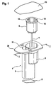
- FIG. 1 shows an exploded view of an embodiment of the cartridge having a housing 1, which encloses a holding chamber 5 and a laterally attached to the holding chamber test chamber 3.
- a circumferential flange 20 which projects beyond the holding chamber 5 and the test chamber 3.
- the geometry of the housing 1 is selected to minimize the likelihood of trapping an air bubble in the cartridge.
- an inclined floor 17 (s. Figures 2 and 3 ) of the holding chamber 5 to keep the air entrapment small when test liquid is filled in the holding chamber 5 through an opening 21. Due to the geometry of the housing 1 as large a surface contact of the test liquid is achieved with the heated housing wall, while the surface of the test liquid; which is exposed to the air is minimized.
- a measuring cell 8 can be used, to which a capillary tube 9 is attached.
- barrier ribs 18 for positioning a suction port 13 of a suction device 12 (s. Figures 2 and 3 ) appropriate.
- four such barrier ribs 18 are provided, of which in Fig. 1 two and in Fig. 2 three are shown.
- the measuring cell 8 has a peripheral upper edge 16.
- FIG. 2 shows a first embodiment of the cartridge, in which the capillary tube 9 projects into the interior of the measuring cell 8.
- the cartridge contains in the holding chamber 5, a liquid volume 7.
- the liquid volume 7 is built up by the filled test liquid 4.
- the holding chamber 5 is closed by a separating element 2, specifically at a height such that an air cushion 6 is located above the level of the test liquid 4.
- FIG. 2 the configuration between the suction device 12 and the cartridge is shown after the suction port 13 of the suction device 12 has come into contact with the measuring cell 8 and pushed it down into the test chamber so that the measuring cell 8 is seated on a circumferential base 11, which is attached to the inner wall of the test chamber 3.
- the measuring cell 8 is cylindrical and has a diameter smaller than the inner diameter of the test chamber 3.
- the upper slightly bulged edge 16 of the measuring cell 8 abuts against the inner wall of the test chamber 3.
- a sealing element 15 is attached, which closes the test chamber airtight to the outside atmosphere.
- the capillary tube 9 pierces the separating element 2 and comes into contact with the test liquid 4 in the liquid volume 7 or dips into this test liquid 4.
- a negative pressure in the measuring cell 8 is generated by the suction device 12.
- the suction port 13 is provided on its outer side with an O-ring 14 which rests on the edge 16 of the measuring cell 8 and contributes to the sealing of the measuring cell with respect to the outside atmosphere. Due to the applied negative pressure to the measuring cell 8 test liquid 4 flows from the liquid volume 7 through the capillary tube 9 into the measuring cell 8, and it forms a liquid volume 10 with increasing level.
- the test liquid 4 contains a mixture of glycerol and water, and its viscosity is adjusted to correspond to the viscosity of normal blood.
- the ratio of glycerol to water is 30:70 to 40:60, based on the total weight of the mixture of glycerol and water.
- the ratio of glycerol to water is 35:65 percent by weight, based in each case on the total weight of the mixture of glycerol and water.
- the initial flow rate of the test liquid 4 is controlled by changing the length and the inner diameter of the capillary tube 9.
- the inner diameter of the capillary tube 9 is in the range of 100 to 220 microns, in particular it is 150 to 210 microns.
- the length of the capillary tube 9 is in the range of 15 to 30 mm. In a preferred embodiment. the inner diameter of the capillary tube is 200 ⁇ 10 ⁇ m and the length of the capillary tube is 30 mm.
- the initial flow rate (IF) is 150 to 200 ⁇ l / min with a tolerance of about ⁇ 2.5 to 3%.
- the total volume of test fluid 4 is 300 to 400 ⁇ l, with a tolerance of ⁇ 5 to 7%.
- the capillary tube 9 With the configuration of the capillary tube 9 given above and the conditions for the initial flow rate and the total volume of the test liquid 4, there is a shutter time of about 120 to 180 seconds, with a tolerance of ⁇ 5 sec. Viscosity, total volume and initial volume. Flow rate of the test liquid 4 and the negative pressure in the measuring cell 8 determine the shutter speed of the test liquid. If it is necessary for some assays to increase or decrease the shutter time, the viscosity of the test fluid 4 may be increased or decreased by changing the ratio between glycerol and water. If the capillary tube 9 is shortened, the inner diameter of the capillary tube may also be reduced to maintain the initial flow rate.
- the total volume of Reduce test liquid With a shortening of the capillary tube with a constant inner diameter, the total volume of Reduce test liquid to keep the flow rate constant.
- the size of the initial flow rate, the total volume of test fluid, the volume of air or air cushion 6, and the viscosity of the test fluid are selected to meet the standardized shutter speed of 120 to 180 seconds, which is consistent with the normal blood shutter speed. If it turns out during a measurement that the shutter speed of the test fluid deviates from the standardized shutter speed, it can be assumed that the device under test for the platelet diagnostics does not function properly.
- the material for the capillary tube 9 is preferably stainless steel, in which the predetermined tight tolerance for the inner diameter of a relatively smooth inner surface can be maintained.
- the measuring cell 8 expediently consists of a plastic such as polypropylene or polyethylene terephthalate.
- FIG. 3 a further embodiment of the cartridge is shown in section.
- This embodiment differs from that in FIG. 2 shown embodiment only in that the capillary tube 9 is integrated with the measuring cell 8, in such a way that the capillary tube is integrally connected to the underside of the measuring cell 8 without hineinzieuragen into the measuring cell.
- the top of the measuring cell 8 is closed except for a small opening 22.
- This opening 22 is connected to a suction port of the suction device 12.
- the capillary tube 9 has likewise pierced the separating element 2 and is in contact with the test liquid 4 of the liquid volume 7.
- the suction device 12 which rests sealingly on the measuring cell 8 via the O-ring 14, has the measuring cell 8 in the test chamber 3 pushed down so far that the measuring cell is seated on the base 11.
- the measuring cell 8 the barrier ribs can be omitted, since the measuring cell is closed on all sides except for the small opening 22.
- the test liquid 4 rises through the capillary tube 9 into the measuring cell and forms there an increasing volume of liquid 10 until the negative pressure in the Air cushion 6 above the liquid volume 7 is equal to the applied negative pressure in the measuring cell 8.
- the single-use cartridge is discarded together with the test liquid 4 within the measuring cell 8 at the end of the test.
- the in the Figures 2 and 3 The disposable cartridge shown is prepared for the test by the following steps. First, the test liquid 4 is filled in the holding chamber 5, and then the holding chamber 5 is closed airtight with the separating element 2. Next, a measuring cell 8 is introduced into the test chamber 3 and the test chamber by means of a sealing element 15, which on the inner wall of the housing 1 of the cartridge and an intermediate wall between the test chamber. 3 and the holding chamber 5 is applied, hermetically sealed. Thereafter, the top of the housing 1 is sealed airtight with a closure 19.
- the measuring cell 8 is located in a position next to the closure 19, wherein the capillary tube 9 connected to the measuring cell 8 is arranged with its lower end above the separating element 2, ie the separating element 2 is not pierced by the capillary tube 9.
- the closure 19 above the test chamber 3 is removed prior to inserting the cartridge into the device for platelet diagnostics.
- the capillary tube 9 connected to the measuring cell 8 is moved within the test chamber 3 in the direction of the separating element 2, caused by the pressure exerted by the suction device 12 mechanical pressure on the measuring cell 8, whereby these down to touchdown on the base 11th is pushed.
- the capillary tube 9 pierces the separating element and comes into contact with the test liquid 4 of the liquid volume 7 or dips into the test liquid.
- a sufficient negative pressure in the measuring cell is generated, so that test liquid flows through the capillary tube 9 into the measuring cell and there is a liquid volume 10 is constructed. It measures the time it takes for the flow of test fluid to stop in the measuring cell. The beginning of the time measurement marks the application of the negative pressure to the measuring cell. The resulting shutter speed will increase with time for blood flow correlated in a predetermined normal range of the device for platelet diagnostics.
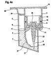
- FIG. 4a shows a third embodiment of the cartridge, which is similar to the first embodiment according to FIG. 2 is designed.
- the sealing element 15 is formed in this embodiment as an O-ring.
- the capillary tube is surrounded by a casing 23 within the holding chamber 5, and as far as the capillary tube 9 projects into the measuring cell 8, it is enveloped by a further casing 26. Although this is the case in the embodiments according to FIGS Figures 2 and 3 is not shown, it is understood that even in the first and second embodiments, the capillary tube 9 is each surrounded by a sheath 23 or may be and that the first embodiment additionally has a sheath 26 or may have.
- the capillary tube 9 passes through a separating element 25.
- a wall 27 between the holding chamber 5 and the test chamber 3 extends far down to near the inclined bottom 17 and is bent or curved in the lower portion.
- the separating element 25 is located between the wall and a wall of the housing 1 and closes the holding chamber 5 with respect to the test chamber 3.
- the test liquid occupies a liquid volume 7 within the holding chamber 5, wherein the liquid volume fills about half the volume of the holding chamber 5.
- a further separating element 24 which is inserted after the filling of the test liquid 4 in the holding chamber 5 at a distance from the flange 20. Between this separating element 24 and the level of the test liquid 4, the air cushion 6 is enclosed.
- the remaining parts of the cartridge according largely to the first embodiment according to FIG. 2 and are denoted by the same reference numerals as in FIG FIG. 2 occupied, so that they will not be described again.
- the fourth embodiment according to FIG. 4b is similar to the third embodiment according to FIG. 4a built so that only the different features to the third embodiment in the Explained below.
- the opening 21 of the holding chamber 5 is closed after the filling of the test liquid with the separating element 24, which rests on the flange 20.
- the upper closure 19 of the cartridge overhangs the separating element 24 and terminates with the flange 20.
- the holding chamber 5 continues to be hermetically sealed by the separating element 24.
- the closure 19 consists for example of a self-adhesive film.
- the air cushion 6 is larger in the fourth embodiment than in the third embodiment, since the partition member 24, the opening 21 of the holding chamber is flush and not within the holding chamber, as in the third embodiment, is mounted.
- the capillary tube 9 penetrates the separating element 25.
- suction device The configuration between the suction device and the cartridge is the same for the third and fourth embodiments as described with reference to the first embodiment.
- the suction device is not shown, but applies; the negative pressure exerted by the suction device allows the test liquid to flow through the capillary tube 9 into the measuring cell 8 and builds up the liquid volume 10 there until the negative pressure in the air cushion 6 above the liquid volume 7 equals the applied negative pressure in the measuring cell 8.
Abstract
Description
Die Erfindung betrifft eine Kartusche zur Funktionskontrolle einer Vorrichtung für die Untersuchung der Blutplättchenfunktion, mit einem Gehäuse, das eine Testkammer und eine Haltekammer umschließt und ein Verfahren zur Funktionskontrolle einer derartigen Vorrichtung sowie die Verwendung einer Testflüssigkeit in der Vorrichtung.The invention relates to a cartridge for functional control of a device for the examination of platelet function, comprising a housing which encloses a test chamber and a holding chamber and a method for functional control of such a device and the use of a test liquid in the device.
In einer Vorrichtung für die automatisierte Untersuchung der Blutplättchenfunktion werden Testkartuschen eingesetzt, die bioaktive poröse Trennelemente enthalten. Mit der Vorrichtung werden Untersuchungen oder Tests des Blutgerinnungsprozesses anhand der Blutplättchenfunktion durchgeführt, wobei einige oder alle Schritte einer Untersuchung automatisch ablaufen.In an automated platelet function assay device, test cartridges containing bioactive porous separators are used. The device performs examinations or tests of the blood coagulation process on the basis of the platelet function, with some or all steps of an examination taking place automatically.
Die Hämostase oder Blutstillung beinhaltet das Zusammenspiel von zwei biochemischen Systemen, die durch verschiedene Proteinfaktoren und zelluläre Komponenten, z. B. Blutplättchen, gesteuert werden. Die Vorgänge, durch die Blut gerinnt, beinhalten nach derzeitigem Verständnis eine mehrstufige Kaskade von Aktivierungen der Proteinfaktoren, die in der Fibrinbildung gipfeln. Verschiedene. Tests wurden entwickelt, um die einzelnen Stufen dieser Kaskade zu testen und so bestimmen zu können, ob das Blut eines Patienten einwandfrei gerinnen kann oder ob eine Gerinnungsstörurig mit einem Mangel an einem oder mehreren der zur Blutgerinnung notwendigen Faktoren vorliegt. Es ist bekannt, dass der Zustand der Blutplättchen oder die Blutplättchenfunktion einen Hinweis auf die Fähigkeit des Blutes zur einwandfreien Gerinnung gibt.Hemostasis or hemostasis involves the interaction of two biochemical systems that are affected by different protein factors and cellular components, e.g. As platelets are controlled. The processes by which blood clots, as currently understood, involve a multi-level cascade of activations of protein factors culminating in fibrin formation. Various. Tests have been developed to test each stage of this cascade to determine if a patient's blood can clot properly or if there is a coagulation disorder with a deficiency in one or more of the factors necessary for blood clotting. It is known that the condition of the platelets or the platelet function gives an indication of the ability of the blood to clot properly.
Der Test zum Untersuchen der Plättchenfunktiön oder der primären Hämostase an menschlichem Vollblut ist als Blutungszeittest bekannt. Der Blutungszeittest, der mehrere Dekaden angewandt wurde, beinhaltet einen Einschnitt am Unterarm des Patienten. Zur Vermeidung eines Einschnitts wurde daher ein weiterer Test entwickelt, der wesentlich genauer die Blutplättchendiagnose erstellen kann.The assay for assaying platelet function or primary hemostasis on whole human blood is known as a bleeding time test. The bleeding time test, which has been used for several decades, involves an incision on the patient's forearm. To avoid an incision Therefore, another test has been developed that can provide much more accurate blood platelet diagnosis.
Die
Die mit dem Thrombostat™ 4000 verwendete Vorrichtung besteht aus drei getrennten Teilen: einer Reagenz-/Testkammer, einer Kapillare und einem Probenapf. Eine poröse Trennwand, die Collagen enthält, befindet sich in der Reagenz-/Testkammer. Die Reagenz-/Testkammer muss in einer hermetischen Verpackung, von der Kapillare und dem Probenapf getrennt, aufbewahrt werden, um die Stabilität des Collagens während der angegebenen Lagerungszeit aufrecht zu erhalten. Die Kapillare und die Reagenz-/Testkammer müssen zu Beginn jedes durchgeführten Tests von der Bedienperson manuell zusammengesetzt werden. Weiterhin muss die zu testende Probe in den Probenapf pipettiert und inkubiert werden, bevor der Probenapf mit der Kapillare und der Reagenz-/Testkammer zusammengesetzt werden kann. Außerdem wird die Zeit für den Inkubationsschritt von der Bedienperson manuell bestimmt. Der getrennte Inkubationsschritt erfordert eine zusätzliche Handhabung nach der Inkubationszeit, wenn die Bedienperson die zusammengesetzte Kapillare und Reagenz-/Testkammer manuell in den Probenapf einsetzt und die Testsequenz initiiert. Am Ende des Tests wird die teure Kapillare wieder verwendet und muss daher zeitaufwändig gereinigt werden.The device used with the Thrombostat ™ 4000 consists of three separate parts: a reagent / test chamber, a capillary, and a sample cup. A porous partition containing collagen is located in the reagent / test chamber. The reagent / test chamber must be kept in a hermetic package, separate from the capillary and sample cup, to maintain collagen stability during the indicated storage period. The capillary and reagent / test chamber must be manually assembled by the operator at the beginning of each test performed. Furthermore, the sample to be tested must be pipetted into the sample cup and incubated before the sample cup can be assembled with the capillary and the reagent / test chamber. In addition, the time for the incubation step is manually determined by the operator. The separate incubation step requires additional handling after the incubation period when the operator manually inserts the assembled capillary and reagent / test chamber into the sample cup and initiates the test sequence. At the end of the test, the expensive capillary is reused and therefore requires time-consuming cleaning.
Zur Vermeidung dieser Nachteile ist aus der
Die komplexen Vorgänge in der Primär-Hämostase führen über Thrombocytenadhäsion und -aggregation zur Pfropfbildung. Bekannte Geräte messen die Zeit, die unter standardisierten Bedingungen hierfür notwendig ist. Das Ergebnis der Zeitmessung ist die sogenannten Verschlusszeit, die in Sekunden angegeben wird. Sie ist ein Maß für die Plättchen-Hämostase-Kapazität.The complex processes in primary hemostasis lead to graft formation via platelet adhesion and aggregation. Known devices measure the time required under standardized conditions. The result of the time measurement is the so-called shutter speed, which is given in seconds. It is a measure of platelet hemostasis capacity.
Bei der Untersuchung werden plasmatische und zelluläre Komponenten der Primär-Hämostase erfasst. Dies geschieht durch in-vitro-Simulation der physiologischen Bedingungen, die zu Adhäsion, Aktivierung und Aggregation der Thrombocyten führen.The examination covers the plasmatic and cellular components of primary hemostasis. This is done by in vitro simulation of the physiological conditions that lead to adhesion, activation and aggregation of thrombocytes.
Bei den Vorrichtungen für die Plättchenfunktionsdiagnostik werden beim Durchfluss einer gepufferten Natriumcitrat-Vollblutprobe durch eine mit Collagen (Col) und einem weiteren Aktivator wie Epinephrin (Epi) oder Adenosin-5'-diphosphat (ADP) beschichtete Membranöffnung die Verhältnisse simuliert, die in einem Blutgefäß herrschen. Die Plättchen reagieren in Anwesenheit der plasmatischen Komponenten, beispielsweise des v. Willebrand-Faktors unter Druck- und Scherkraftverhältnissen, die denen eines kleinen verletzten Blutgefäßes entsprechen. Durch Adhäsion und Aggregation der Thrombocyten kommt es zum Verschluss der Membranöffnung. Die Zeit gemessen vom Beginn der Messung bis zum Verschluss der Membranöffnung ist die schon erwähnte Verschlusszeit. Die Entscheidungsgrenzen in klinischen Studien ergeben sich unter Berücksichtigung der sich überlappenden Verschlusszeiten normaler und anomaler Populationen beim PFA- 100® -System anhand folgender Referenzbereiche:
Mit den bekannten Vorrichtungen für die Plättchenfunktionsdiagnostik steht für Risikopatienten mit angeborener Thrombocyten-Funktionsstörung somit eine einfache Screening-Möglichkeit zur Verfügung. Die Messzellen bzw. Testkartuschen dieser Vorrichtungen erlauben die Unterscheidung zwischen normaler und anomaler Plättchenfunktion (Col/Epi) und die Erkennung einer Acetylsalicylsäure induzierten Störung (Col/ADP). Durch die Plättchenfunktionsdiagnostik können sehr viele Patienten mit angeborenen Thrombocyten-Funktionsstörungen diagnostiziert werden, ohne dass eine weitere Spezialdiagnostik wie z. B. die Aggregometrie benötigt wird. Bei Einnahme von Acetylsalicylsäure werden im Serum sehr rasch ansteigende und wieder abklingende Medikamentenkonzentrationen gemessen. Die Folge ist ein Ansteigen der Col/Epi-Verschlusszeiten, die über Tage verlängert bleiben. Individuell sind bei Patienten unterschiedlich starke Verlängerungen der Verschlusszeiten festgestellt worden.With the known devices for platelet function diagnostics, a simple screening option is thus available for risk patients with congenital platelet dysfunction. The measuring cells or test cartridges of these devices allow the distinction between normal and abnormal platelet function (Col / Epi) and the detection of an acetylsalicylic acid-induced disorder (Col / ADP). Platelet function diagnostics can diagnose many patients with congenital platelet dysfunction without having to undergo further specialized diagnostics such as: B. the aggregometry is needed. When taking acetylsalicylic acid in the serum very rapidly increasing and decreasing drug concentrations are measured. The result is an increase in Col / Epi shutter speeds that remain extended for days. Individually, patients have experienced varying degrees of shutter speed extension.
In den
Die bei den bekannten Vorrichtungen eingesetzten porösen Trennelemente in den Testkartuschen eignen sich für Vollblut- und Blutplasmakoagulationsassays, die den Prothrombinzeittests und den partiellen Thromboplastinzeittests zur Bewertung von Gerinnungsfunktionen ähnlich sind. Die Pfropfbildung wird durch Kontakt des Blutes mit geeigneten Aktivatoren für exogene bzw. endogene Aktivierung eingeleitet. Die Aktivatoren sind in die porösen Trennelemente eingebaut. Die zum Stoppen des Blutflusses erforderliche Zeit wird beispielsweise mit der Prothrombinzeit oder der partiellen Thromboplastinzeit der zu untersuchenden Personen korreliert.The porous separators used in the prior art devices in the test cartridges are suitable for whole blood and blood plasma coagulation assays that are similar to the prothrombin time assays and the partial thromboplastin time tests for assessing coagulation functions. The grafting is initiated by contact of the blood with suitable activators for exogenous or endogenous activation. The activators are built into the porous separators. The time required to stop the blood flow is correlated, for example, with the prothrombin time or the partial thromboplastin time of the persons to be examined.
Die Konzentration des oder der Mittel in den porösen Trennelemente wird so gewählt, dass sich eine Verschlusszeit ergibt, die einen Unterschied zwischen normalen und anomalen Gerinnungsparametern anzeigt. Beim Plättchenfunktionstest ist Adenosin-5'-diphosphat (ADP) ein bevorzugtes Reagenz für den Einbau in die porösen Trennelemente. Die Verschlusszeit hängt bei einer normalen Blutprobe zum Teil von der Konzentration der biologisch aktiven Substanz ab, die in die Membran eingebaut ist. Die Konzentration dieser Substanz wird so gewählt, dass eine gute Unterscheidung zwischen normalem und anomalem Koagulationsparameter erhalten wird. Die Reagenzkonzentration kann unter Berücksichtigung der gewünschten Empfindlichkeit des Assays optimiert werden. Es ist wünschenswert, dass die Konzentration an ADP ausreichend ist, um eine geringfügige Thrombocytendysfunktion nachweisen zu können, aber nicht so niedrig ist, dass variable Ergebnisse erhalten werden.The concentration of the agent or agents in the porous separators is selected to give a shutter time that indicates a difference between normal and abnormal coagulation parameters. In the platelet function test, adenosine 5'-diphosphate (ADP) is a preferred reagent for incorporation into the porous separators. The shutter speed of a normal blood sample depends, in part, on the concentration of biologically active substance incorporated in the membrane. The concentration of this substance is chosen so as to obtain a good distinction between normal and abnormal coagulation parameters. The reagent concentration can be optimized taking into account the desired sensitivity of the assay. It is desirable that the concentration of ADP be sufficient to detect a minor thrombocyte dysfunction, but not so low as to give variable results.
Bei den bekannten Vorrichtungen für die Blutplättchendiagnostik stellt sich das Problem die technischen Funktionsabläufe vor Beginn eines Assays zu überprüfen bzw. zu kontrollieren. Diese Funktionskontrolle der Vorrichtungen unterscheidet sich völlig von dem Selbsttest der Vorrichtungen, bei dem beispielsweise Betriebsspannung, Stromaufnahme, Betriebstemperatur, Aufheizzeit für die Probe und dergleichen überprüft werden.In the known devices for blood platelet diagnostics, the problem arises to check the technical functional sequences before starting an assay or to control. This function control of the devices is completely different from the self-test of the devices, in which, for example, operating voltage, current consumption, operating temperature, heating time for the sample and the like are checked.
Aufgabe der Erfindung ist es, die technischen Funktionsabläufe einer Vorrichtung für die Blutplättchendiagnostik zu überprüfen.The object of the invention is to check the technical functional sequences of a device for blood platelet diagnostics.
Diese Aufgabe wird durch die in den Ansprüchen beschriebenen Gegenstände und Verfahren, insbesondere durch eine Vorrichtung der eingangs beschriebenen Art in der Weise gelöst, dass' ein Trennelement ein Flüssigkeitsvolumen und ein darüber befindliches Luftpolster in der Haltekammer luftdicht abschließt, dass eine Messzelle in den oberen Teil der Testkammer einsetzbar ist und dass ein Kapillarrohr die Messzelle mit dem Flüssigkeitsvolumen verbindet.This object is achieved by the objects and methods described in the claims, in particular by a device of the type described above in such a way that 'a separating element a liquid volume and an overlying air cushion in the holding chamber hermetically seals that a measuring cell in the upper part the test chamber is used and that a capillary tube connects the measuring cell with the liquid volume.
In Ausgestaltung der Vorrichtung ist die Haltekammer von einem oberen Verschluss luftdicht abschließbar. Die Messzelle sitzt zweckmäßigerweise luftdicht auf einem umlaufenden Sockel auf, der an der Innenwand der Testkammer angebracht ist. An die Messzelle ist abdichtend eine Saugvorrichtung anschließbar, die einen Unterdruck in der Messzelle erzeugt.In an embodiment of the device, the holding chamber is hermetically sealed by an upper closure. The measuring cell expediently sits airtight on a circumferential base, which is attached to the inner wall of the test chamber. A suction device, which generates a negative pressure in the measuring cell, can be sealingly connected to the measuring cell.
In einer bevorzugten Ausgestaltung der Erfindung enthält die Testflüssigkeit ein Gemisch aus Glycerin und Wasser. Aber auch andere Flüssigkeiten oder deren Gemische werden erfindurigsgemäß als Testflüssigkeit eingesetzt, wobei diese je nach speziellem Anwendungszweck im Vergleich zu der Viskosität der zu testenden Probe, z. B. Vollblut, plättchenreiches Blutplasma, Blutplasma, eine vergleichbare, d. h. im Rahmen der normalen Schwankungsbreite identische, niedrigere oder höhere Viskosität aufweisen. Als Testflüssigkeit geeignete Flüssigkeiten sind z. B. Wasser, Glycerin, Öle, Polyethylenglycol und deren Gemische. Die Testflüssigkeit kann auch noch weitere Komponenten enthalten, die z. B. die Stabilität und/oder die Haltbarkeit der Testflüssigkeit erhöhen oder deren Viskosität verändern können, z. B. Puffersubstanzen, Salze, antimikrobiell wirkende Substanzen, Nukleinsäureketten, Kohlehydratketten, Proteine etc. Die Viskosität der zu testenden Probe und der Testflüssigkeit kann z. B. mit handelsüblichen Viskosimetern bestimmt werden.In a preferred embodiment of the invention, the test liquid contains a mixture of glycerol and water. But other liquids or mixtures thereof are inventively used as a test liquid, these depending on the particular application in comparison to the viscosity of the sample to be tested, for. B. Whole blood, platelet-rich blood plasma, blood plasma, a comparable, ie within the normal range of variation identical, lower or higher viscosity. As a test liquid suitable liquids are for. As water, glycerol, oils, polyethylene glycol and mixtures thereof. The test liquid may also contain other components that z. B. increase the stability and / or durability of the test liquid or can change their viscosity, for. B. buffer substances, salts, antimicrobial substances, nucleic acid chains, carbohydrate chains, proteins, etc. The Viscosity of the sample to be tested and the test liquid can, for. B. be determined with commercial Viskosimetern.
Ein besonders bevorzugtes erfindungsgemäßes Verfahren zur Funktionskontrolle einer Vorrichtung für die Untersuchung der Blutplättchenfunküon umfasst folgende Schritte:
- a) Bereitstellen eines Flüssigkeitsvolumens einer Testflüssigkeit in einer Haltekammer;
- b) luftdichtes Abschließen des Flüssigkeitsvolumens und eines darüber befindlichen Luftpolsters mit einem Trennelement;
- c) luftdichtes Abschließen der Testkammer mittels eines Dichtungselements und Einbringen einer Messzelle in die Testkammer;
- d) Bewegen eines mit einer Messzelle verbundenen Kapillarrohrs innerhalb der Testkammer in Richtung auf das Trennelement zu und Durchstoßen des Trennelements mit dem Kapillarrohr, so dass dieses mit der Testflüssigkeit in Kontakt gelangt bzw. in die Testflüssigkeit eintaucht;
- e) Erzeugen eines ausreichenden Unterdrucks in der Messzelle, so dass Testflüssigkeit durch das Kapillarrohr hindurch in die Messzelle fließt;
- f) Messen der Zeit, die benötigt wird, bis der Fluss der Testflüssigkeit in die Messzelle aufhört; und
- g) Korrelieren der im Schritt (f) gemessenen Zeit mit einem vorbestimmten Referenzwert.
- a) providing a liquid volume of a test liquid in a holding chamber;
- b) airtight closing of the liquid volume and an overlying air cushion with a separating element;
- c) airtight sealing of the test chamber by means of a sealing element and introduction of a measuring cell into the test chamber;
- d) moving a capillary tube connected to a measuring cell within the test chamber in the direction of the separating element and piercing the separating element with the capillary tube so that it comes into contact with the test liquid or is immersed in the test liquid;
- e) generating a sufficient negative pressure in the measuring cell, so that test liquid flows through the capillary tube into the measuring cell;
- f) measuring the time it takes for the flow of test fluid to stop in the measuring cell; and
- g) correlating the time measured in step (f) with a predetermined reference value.
Der vorbestimmte Referenzwert im Schritt g) ist beispielsweise die Zeit für den Blutfluss in einem vorbestimmten Normalbereich der Vorrichtung für die Untersuchung der Blutplättchenfunktion.The predetermined reference value in step g) is, for example, the time for the blood flow in a predetermined normal range of the device for the examination of the platelet function.
Die weitere Ausgestaltung des Verfahrens ergibt sich aus den Verfahrensmaßnahmen der Ansprüche 17 bis 23.The further embodiment of the method results from the method measures of
Die Erfindung ermöglicht es, einen Test zur Bestimmung der Verschlusszeit einer normalen Vollblut- oder Plasmaprobe unter Vorgabe einer Anfangsfließgeschwindigkeit und eines angesaugten Gesamtvolumens der Vollblutprobe mit Hilfe einer Testflüssigkeit zu simulieren. Da die zu erwartende Verschlusszeit bekannt ist, zeigt jede größere Abweichung der Verschlusszeit der Testflüssigkeit an, dass die Einsatzbereitschaft der Vorrichtung für die gewünschte Diagnostik, z. B. Blutplättchendiagnostik, nicht gegeben ist. So kann beispielsweise ein Leck zwischen Saugvorrichtung und Messzelle der Vorrichtung zu längeren Verschlusszeiten der Restflüssigkeit führen.The invention makes it possible to simulate a test for the determination of the shutter time of a normal whole blood or plasma sample under specification of an initial flow rate and a total aspirated volume of the whole blood sample with the aid of a test liquid. Since the expected shutter speed is known, any major deviation in the shutter speed of the test fluid indicates that the device is ready for use for the desired diagnostic, e.g. B. platelet diagnostics, is not given. For example, a leak between the suction device and the measuring cell of the device can lead to longer shutter speeds of the residual fluid.
Das Messprinzip für die Verschlusszeit der Testflüssigkeit besteht darin, dass die Zeit von Fließbeginn der Testflüssigkeit an bis zum Fließstopp, verursacht durch den Druckausgleich zwischen dem Unterdruck in der Haltekammer und dem Saugdruck in der Messzelle, in Zeiteinheiten wie z. B. in Sekunden gemessen wird.The measuring principle for the shutter speed of the test liquid is that the time from the start of flow of the test liquid until the flow stop, caused by the pressure equalization between the negative pressure in the holding chamber and the suction pressure in the measuring cell, in time units such. B. measured in seconds.
Die Reproduzierbarkeit der Verschlusszeit ist sehr gut, wobei die Abweichungen in den Parametern angesaugtes Gesamtvolumen der Testflüssigkeit und Anfangsfließgeschwindigkeit mit 1 bis 2 % sehr gering ausfallen.The reproducibility of the shutter speed is very good, with the deviations in the parameters aspirated total volume of the test fluid and initial flow rate being very low at 1 to 2%.
Spezielle Ausführungsformen der Erfindung werden im Folgenden anhand von zeichnerisch dargestellten Ausführungsbeispielen näher erläutert. Es zeigen:
-
Figur 1 -
Figur 2Figur 1 in Kontakt mit einem Sauganschluss einer Saugvorrichtung; -
Figur 3Figur 1 in Kontakt mit einem Sauganschluss einer Saugvorrichtung. -
Figuren 4a Schnittdarstellungen einer dritten und vierten Ausführungsform der Kartusche und 4b entlang der Linie I-I derFigur 1
-
FIG. 1 in an exploded view of a cartridge for functional control of a device for platelet diagnostics according to the invention; -
FIG. 2 a sectional view of a first embodiment of the cartridge along the line II ofFIG. 1 in contact with a suction port of a suction device; -
FIG. 3 a sectional view of a second embodiment of the cartridge along the line II ofFIG. 1 in contact with a suction port of a suction device. -
FIGS. 4a Sectional views of a third and fourth embodiment of the cartridge and 4b along the line II ofFIG. 1 ,
Die erfindungsgemäße Kartusche für die Funktionskontrolle wird anhand von Ausführungsformen erläutert, die in Vorrichtungen für die Blutplättchendiagnostik eingesetzt werden. Die äußere Gestalt und die Abmessungen des Gehäuses einer solchen Kartusche stimmen daher mit J den Testkartuschen überein, wie sie in den
Die Messzelle 8 weist einen umlaufenden oberen Rand 16 auf.The measuring
Die
Die Schnittansicht der
In
Die Testflüssigkeit 4 enthält beispielsweise ein Gemisch aus Glycerin und Wasser und ihre Viskosität wird so eingestellt, dass sie der Viskosität von normalem Blut entspricht. Dazu beträgt das Verhältnis Glycerin zu Wasser 30:70 bis 40:60, bezogen auf das Gesamtgewicht der Mischung aus Glycerin und Wasser. Insbesondere beträgt das Verhältnis Glycerin zu Wasser 35:65 Gewichtsprozent, jeweils bezogen auf das Gesamtgewicht der Mischung aus Glycerin und Wasser.For example, the test liquid 4 contains a mixture of glycerol and water, and its viscosity is adjusted to correspond to the viscosity of normal blood. For this purpose, the ratio of glycerol to water is 30:70 to 40:60, based on the total weight of the mixture of glycerol and water. In particular, the ratio of glycerol to water is 35:65 percent by weight, based in each case on the total weight of the mixture of glycerol and water.
Die anfängliche Fließgeschwindigkeit der Testflüssigkeit 4 wird durch Veränderung der Länge und des Innendurchmessers des Kapillarrohrs 9 gesteuert. Der Innendurchmesser des Kapillarrohrs 9 liegt im Bereich von 100 bis 220 µm, insbesondere beträgt er 150 bis 210 µm. Die Länge des Kapillarrohrs 9 liegt im Bereich von 15 bis 30 mm. In einer bevorzugten Ausführungsform. beträgt der Innendurchmesser des Kapillarrohrs 200 ± 10 µm und die Länge des Kapillarrohrs 30 mm. Die anfängliche Fließgeschwindigkeit (IF = Initial Flow Speed) beträgt 150 bis 200 µl/min mit einer Toleranz von etwa ± 2,5 bis 3 %. Das Gesamtvolumen an Testflüssigkeit 4 beträgt 300 bis 400 µl, mit einer Toleranz von ± 5 bis 7 %. Mit der voranstehend angegebenen Konfiguration des Kapillarohrs 9 und den Bedingungen für die anfängliche Fließgeschwindigkeit und das Gesamtvolumen der Testflüssigkeit 4 ergibt sich eine Verschlusszeit von etwa 120 bis 180 sec, mit einer Toleranz von ± 5 sec. Die Viskosität, das Gesamtvolumen und die anfängliche. Fließgeschwindigkeit der Testflüssigkeit 4 sowie der Unterdruck in der Messzelle 8 bestimmen die Verschlusszeit der Testflüssigkeit. Wenn es für einige Assays erforderlich ist die Verschlusszeit zu verlängern oder zu verkürzen, so kann die Viskosität der Testflüssigkeit 4 durch Änderung des Verhältnisses zwischen Glycerin und Wasser erhöht oder erniedrigt werden. Falls das Kapillarrohr 9 verkürzt wird, kann auch der Innendurchmesser des Kapillarrohrs verringert werden, um die anfängliche Fließgeschwindigkeit beizubehalten. Bei einer Verkürzung des Kapillarrohrs bei gleichbleibendem Innendurchmesser ist das Gesamtvolumen der Testflüssigkeit zu verringern, um die Fließgeschwindigkeit konstant halten zu können. Je größer das Luftvolumen, d..h. das anfängliche Luftpolster 6 über dem Flüssigkeitsvolumen 7 ist, desto länger ist die Verschlusszeit der Testflüssigkeit. Die Größe der anfänglichen Fließgeschwindigkeit, des Gesamtvolumens an Testflüssigkeit, des Luftvolumens bzw. des Luftpolsters 6 und die Viskosität der Testflüssigkeit werden so gewählt, dass die standardisierte Verschlusszeit von 120 bis 180 sec eingehalten wird, die mit der Verschlusszeit von normalem Blut übereinstimmt. Wenn sich bei einer Messung herausstellt, dass die Verschlusszeit der Testflüssigkeit von der standardisierten Verschlusszeit abweicht, kann davon ausgegangen werden, dass die überprüfte Vorrichtung für die Blutplättchendiagnostik nicht einwandfrei funktioniert. Das Material für das Kapillarrohr 9 ist bevorzugt Edelstahl, bei dem die vorgegebene enge Toleranz für den Innendurchmesser einer relativ glatten Innenfläche eingehalten werden kann. Die Messzelle 8 besteht zweckmäßigerweise aus einem Kunststoff wie Polypropylen oder Polyethylenterephthalat.The initial flow rate of the test liquid 4 is controlled by changing the length and the inner diameter of the
In
Die zur einmaligen Verwendung vorgesehene Kartusche wird zusammen mit der Testflüssigkeit 4 innerhalb der Messzelle 8 am Ende des Testes verworfen. Die in den
The single-use cartridge is discarded together with the test liquid 4 within the measuring
Das Dichtungselement 15 ist bei dieser Ausführungsform als O-Ring ausgebildet. Das Kapillarrohr ist innerhalb der Haltekammer 5 von einer Ummantelung 23 umgeben und soweit das Kapillarrohr 9 in die Messzelle 8 hineinragt, wird es von einer weiteren Ummantelung 26 umhüllt. Obgleich dies in den Ausführungsformen gemäß den
Eine Wand 27 zwischen der Haltekammer 5 und der Testkammer 3 reicht weit nach unten bis nahe an den geneigten Boden 17 und verläuft im unteren Abschnitt geknickt oder gekrümmt. Das Trennelement 25 befindet sich zwischen der Wand und einer Wand des Gehäuses 1 und verschließt die Haltekammer 5 gegenüber der Testkammer 3. Die Testflüssigkeit nimmt ein Flüssigkeitsvolumen 7 innerhalb der Haltekammer 5 ein, wobei das Flüssigkeitsvolumen etwa das halbe Volumen der Haltekammer 5 ausfüllt. Im oberen Teil des Haltekammer 5 befindet sich ein weiteres Trennelement 24, das nach dem Einfüllen der Testflüssigkeit 4 in die Haltekammer 5 mit Abstand zu dem Flansch 20 eingefügt wird. Zwischen diesem Trennelement 24 und dem Pegel der Testflüssigkeit 4 ist das Luftpolster 6 eingeschlossen. Die übrigen Teile der Kartusche entsprechend weitgehend der ersten Ausführungsform gemäß
Die vierte Ausführungsform nach
Das Kapillarrohr 9 durchdringt das Trennelement 25.The
Die Konfiguration zwischen der Saugvorrichtung und der Kartusche ist für die dritte und vierte Ausführungsform die gleiche wie sie anhand der ersten Ausführungsform beschrieben ist. Aus Gründen der besseren Übersicht ist in den
Durch längere oder kürzere Verschlusszeiten im Vergleich mit der standardisierten Verschlusszeit für normales Blut oder.anderen zu testenden Proben und höhere oder niedrigere anfängliche Fließgeschwindigkeiten der Testflüssigkeit können neben normalen auch anomale Blutzustände simuliert und damit die Funktionskontrolle von Vorrichtungen für die Blutplättchendiagnostik in Bezug auf anomale Blutzusammensetzungen durchgeführt werden. Dies kann durch die Auswahl der entsprechend geeigneten Testflüssigkeit, insbesondere über deren Viskosität im Vergleich mit der Viskosität der zu testenden Probe, in den erfindungsgemäßen Kartuschen sowie anderen erfindungsgemäßen Ausgestaltungsformen erreicht werden.Longer or shorter shutter speeds compared to the standard shutter speed for normal blood or other samples to be tested and higher or lower initial flow rates of the test fluid can simulate abnormal blood states besides normal and thus perform functional control of blood platelet diagnostic devices for abnormal blood compositions become. This can be achieved by selecting the appropriately suitable test liquid, in particular via its viscosity in comparison with the viscosity of the sample to be tested, in the cartridges according to the invention and other embodiments according to the invention.
Claims (24)
- Cartridge for monitoring the function of a device for testing blood platelet function, with a housing (1) which includes a test chamber (3) and a holding chamber (5), characterized in that a separating element (2; 25) closes off in an airtight manner the fluid volume (7) of a test fluid (4) and an air cushion (6) situated above the latter in the holding chamber (5), a measurement cell (8) can be fitted into the upper part of the test chamber (3), and a capillary tube (9) connects the measurement cell to the fluid volume (7).
- Cartridge according to Claim 1, characterized in that the holding chamber (5) can be closed off in an airtight manner by an upper closure element (19).
- Cartridge according to Claim 1 or 2, characterized in that the measurement cell (8) sits on a peripheral base (11) arranged on the inner wall of the test chamber (3).
- Cartridge according to one or more of Claims 1 to 3, characterized in that the measurement cell (8) is cylindrical and has a diameter smaller than the internal diameter of the test chamber (3).
- Cartridge according to one or more of Claims 1 to 4, characterized in that a sealing element (15) between the outside of the measurement cell (8) and the inner wall of the test chamber (3) closes the test chamber off in an airtight manner from the outside atmosphere.
- Cartridge according to one or more of Claims 1 to 5, characterized in that a suction device (12) can be connected sealingly to the measurement cell (8) and generates an underpressure in the measurement cell (8).
- Cartridge according to Claim 6, characterized in that the suction device (12) has a suction attachment (13) which is equipped with an O-ring (14).
- Cartridge according to Claim 7, characterized in that the O-ring (14) lies sealingly on an edge (16) of the measurement cell (8).
- Cartridge according to one or more of Claims 1 to 8, characterized in that the capillary tube (9), with its upper end, protrudes into the measurement cell (8), passes through the separating element (2) and, with its lower end, plunges into the test fluid (4) of the fluid volume (7).
- Cartridge according to one or more of Claims 1 to 9, characterized in that the measurement cell (8) is closed all round, except for a small opening (22) in its top face and except for the capillary tube (9) connected to the measurement cell (8).
- Cartridge according to Claim 10, characterized in that the capillary tube (9) is connected integrally to the underside of the measurement cell (8) without protruding into the measurement cell (8).
- Cartridge according to one or more of Claims 1 to 11, characterized in that the test fluid (4) contains a mixture of glycerol and water.
- Cartridge according to Claim 12, characterized in that the ratio of glycerol to water is 30:70 to 40:60, preferably 35:65 percent by weight, based on the total weight of the mixture of glycerol and water.
- Cartridge according to one or more of Claims 1 to 11, characterized in that the test fluid contains water, oils, polyethylene glycol or mixtures thereof.
- Cartridge according to Claim 12 or 14, characterized in that the test fluid (4) contains buffer substances, salts, antimicrobial substances, nucleic acid chains, carbohydrate chains, proteins.
- Method for monitoring the function of a device for testing blood platelet function, which method comprises the following steps:(a) making ready a fluid volume (7) of a test fluid (4) in a holding chamber (5);(b) closing off the fluid volume (7), and an air cushion (6) located above this, in an airtight manner by means of a separating element (2; 25);(c) closing off the test chamber (3) in an airtight manner by means of a sealing element (15) and introducing a measurement cell (8) into the test chamber;(d) moving a capillary tube (9), connected to a measurement cell (8), inside the test chamber (3) in the direction of the separating element (2; 25) and piercing the separating element with the capillary tube so that the latter comes into contact with the test fluid or plunges into the test fluid;(e) generating a sufficient underpressure in the measurement cell so that test fluid flows through the capillary tube into the measurement cell;(f) measuring the time needed until the flow of the test fluid into the measurement cell stops; and(g) correlating the time measured in step (f) with a predetermined reference value.
- Method according to Claim 16, characterized in that the viscosity of the test fluid is chosen equal to the viscosity of blood or blood plasma in the normal state.
- Method according to Claim 16, characterized in that the viscosity of the test fluid is chosen greater than the viscosity of blood or blood plasma in the normal state, so that the time according to step (f) is lengthened.
- Method according to Claim 16, characterized in that the viscosity of the test fluid is chosen lower than the viscosity of blood or blood plasma in the normal state, so that the time according to step (f) is shortened.
- Method according to one or more of Claims 16 to 19, characterized in that the fluid volume of the test fluid is reduced compared to the initial state in order to lengthen the time according to step (f).
- Method according to one or more of Claims 16 to 20, characterized in that the capillary tube is lengthened in order to lengthen the time according to step (f).
- Method according to one or more of Claims 16 to 21, characterized in that the internal diameter of the capillary tube is reduced in order to lengthen the time according to step (f).
- Method according to Claim 16, characterized in that the viscosity of the test fluid is comparable to or lower or higher than the viscosity of the sample to be tested.
- Method according to one of Claims 16 and 23, characterized in that the test fluid is water, glycerol, oils, polyethylene glycol or a mixture of these, which furthermore preferably contains buffer substances, salts, antimicrobial substances, nucleic acid chains, carbohydrate chains, proteins or mixtures of these.
Applications Claiming Priority (2)
| Application Number | Priority Date | Filing Date | Title |
|---|---|---|---|
| DE10360814A DE10360814A1 (en) | 2003-12-23 | 2003-12-23 | Cartridge for functional control of a device for the examination of platelet function, method for functional control and use of a test liquid |
| DE10360814 | 2003-12-23 |
Publications (3)
| Publication Number | Publication Date |
|---|---|
| EP1547689A2 EP1547689A2 (en) | 2005-06-29 |
| EP1547689A3 EP1547689A3 (en) | 2005-08-03 |
| EP1547689B1 true EP1547689B1 (en) | 2010-10-27 |
Family
ID=34530367
Family Applications (1)
| Application Number | Title | Priority Date | Filing Date |
|---|---|---|---|
| EP04027940A Not-in-force EP1547689B1 (en) | 2003-12-23 | 2004-11-25 | Cartridge for use in the control of the functionality of a device for the analysis of blood platelet functionality, process for the control of functionality, and use of a test liquid |
Country Status (7)
| Country | Link |
|---|---|
| US (1) | US7521247B2 (en) |
| EP (1) | EP1547689B1 (en) |
| JP (1) | JP4630053B2 (en) |
| AT (1) | ATE485887T1 (en) |
| CA (1) | CA2490432A1 (en) |
| DE (2) | DE10360814A1 (en) |
| ES (1) | ES2354977T3 (en) |
Families Citing this family (17)
| Publication number | Priority date | Publication date | Assignee | Title |
|---|---|---|---|---|
| US8448499B2 (en) | 2008-12-23 | 2013-05-28 | C A Casyso Ag | Cartridge device for a measuring system for measuring viscoelastic characteristics of a sample liquid, a corresponding measuring system, and a corresponding method |
| EP4060325A1 (en) * | 2009-12-07 | 2022-09-21 | Meso Scale Technologies, LLC. | Assay cartridge reader |
| US9625465B2 (en) | 2012-05-15 | 2017-04-18 | Defined Diagnostics, Llc | Clinical diagnostic systems |
| US9081001B2 (en) | 2012-05-15 | 2015-07-14 | Wellstat Diagnostics, Llc | Diagnostic systems and instruments |
| US9213043B2 (en) | 2012-05-15 | 2015-12-15 | Wellstat Diagnostics, Llc | Clinical diagnostic system including instrument and cartridge |
| CA2904616C (en) * | 2013-03-15 | 2021-04-27 | Coramed Technologies, Llc | Apparatus, cartridge and method for hemostasis testing |
| US10288630B2 (en) | 2014-09-29 | 2019-05-14 | C A Casyso Gmbh | Blood testing system and method |
| US10816559B2 (en) | 2014-09-29 | 2020-10-27 | Ca Casyso Ag | Blood testing system and method |
| US10539579B2 (en) | 2014-09-29 | 2020-01-21 | C A Casyso Gmbh | Blood testing system and method |
| US10175225B2 (en) | 2014-09-29 | 2019-01-08 | C A Casyso Ag | Blood testing system and method |
| US10473674B2 (en) * | 2016-08-31 | 2019-11-12 | C A Casyso Gmbh | Controlled blood delivery to mixing chamber of a blood testing cartridge |
| US10843185B2 (en) | 2017-07-12 | 2020-11-24 | Ca Casyso Gmbh | Autoplatelet cartridge device |
| US10117615B1 (en) * | 2017-08-01 | 2018-11-06 | Nova Biomedical Corporation | Analyzer cartridge with capillary wiper |
| US20210268497A1 (en) * | 2018-07-29 | 2021-09-02 | Koc Universitesi | Microfluidic thromboelastometry instrument |
| KR102229025B1 (en) * | 2019-07-19 | 2021-03-17 | 전북대학교산학협력단 | Small Blood Viscosity Measurement Kit and Its Cartridge |
| US20210363560A1 (en) * | 2019-09-17 | 2021-11-25 | Nova Biomedical Corporation | Systems and methods for measuring liver enzyme levels in blood |
| CN111190000A (en) * | 2020-03-02 | 2020-05-22 | 美高怡生生物技术(北京)有限公司 | Platelet function determination method and device |
Family Cites Families (12)
| Publication number | Priority date | Publication date | Assignee | Title |
|---|---|---|---|---|
| DE3247815C2 (en) | 1982-12-23 | 1985-10-17 | Gustav Viktor Rudolf Prof. London Born | Device for measuring the bleeding time in vitro |
| DE3541057A1 (en) | 1985-11-19 | 1987-05-21 | Kratzer Michael | METHOD AND DEVICE FOR MEASURING THE AGGREGATION OF BLOOD PLATES OR THE COAGULATION OF THE BLOOD |
| WO1987007128A1 (en) * | 1986-05-30 | 1987-12-03 | Kdl Technologies, Inc. | Apparatus and method for measuring native mammalian blood viscosity |
| DE3739247C2 (en) * | 1987-11-19 | 1996-11-21 | Dade Int Inc | Bleeding time measuring device |
| WO1996000899A1 (en) * | 1994-06-30 | 1996-01-11 | Dade International Inc. | Bioactive porous partition members |
| US5602037A (en) | 1994-06-30 | 1997-02-11 | Dade International, Inc. | Combination reagent holding and test device |
| US5888826A (en) * | 1994-06-30 | 1999-03-30 | Dade Behring Inc. | Combination reagent holding and test device |
| WO1997034698A1 (en) * | 1996-03-22 | 1997-09-25 | Dade International Inc. | Combination reagent holding and test device |
| US5925319A (en) * | 1996-04-30 | 1999-07-20 | Medtronic, Inc. | Test cartridge for evaluating blood platelet functionality |
| US7063942B2 (en) * | 2000-10-06 | 2006-06-20 | Victor Krstec | System and method to simulate hemodynamics |
| US6746872B2 (en) * | 2002-01-16 | 2004-06-08 | Lifescan, Inc. | Control compositions and methods of use for coagulation tests |
| US7247488B2 (en) * | 2003-05-06 | 2007-07-24 | Medtronic, Inc. | Method and kit for testing a multi-channel blood assay cartridge |
-
2003
- 2003-12-23 DE DE10360814A patent/DE10360814A1/en not_active Withdrawn
-
2004
- 2004-11-25 ES ES04027940T patent/ES2354977T3/en active Active
- 2004-11-25 EP EP04027940A patent/EP1547689B1/en not_active Not-in-force
- 2004-11-25 AT AT04027940T patent/ATE485887T1/en not_active IP Right Cessation
- 2004-11-25 DE DE502004011818T patent/DE502004011818D1/en active Active
- 2004-12-16 CA CA002490432A patent/CA2490432A1/en not_active Abandoned
- 2004-12-22 JP JP2004370513A patent/JP4630053B2/en not_active Expired - Fee Related
- 2004-12-22 US US11/017,945 patent/US7521247B2/en not_active Expired - Fee Related
Also Published As
| Publication number | Publication date |
|---|---|
| EP1547689A2 (en) | 2005-06-29 |
| CA2490432A1 (en) | 2005-06-23 |
| ES2354977T3 (en) | 2011-03-21 |
| ATE485887T1 (en) | 2010-11-15 |
| US20050136541A1 (en) | 2005-06-23 |
| EP1547689A3 (en) | 2005-08-03 |
| DE502004011818D1 (en) | 2010-12-09 |
| DE10360814A1 (en) | 2005-07-28 |
| JP2005181339A (en) | 2005-07-07 |
| JP4630053B2 (en) | 2011-02-09 |
| US7521247B2 (en) | 2009-04-21 |
Similar Documents
| Publication | Publication Date | Title |
|---|---|---|
| EP1547689B1 (en) | Cartridge for use in the control of the functionality of a device for the analysis of blood platelet functionality, process for the control of functionality, and use of a test liquid | |
| DE10003093C2 (en) | Device for investigating properties of the global hemostasis function in whole blood or platelet-rich plasma | |
| DE2103841C3 (en) | Blood testing device | |
| DE60026933T2 (en) | Initiation of an analytical measurement in blood | |
| EP0316599B1 (en) | Flow-through apparatus for use in measuring bleeding time, and method for measuring bleeding time | |
| DE60035199T2 (en) | ANALYSIS CASSETTE AND LIQUID CONVEYOR CONTROLLER | |
| DE69731439T2 (en) | COMBINED REAGENT AND TEST ARRANGEMENT | |
| DE60113703T2 (en) | STRIP HOLDER FOR USE IN A TEST STRIP METER | |
| DE60034479T2 (en) | DEVICE AND METHOD FOR DETERMINING COAGULATION IN LIQUID SAMPLES | |
| WO2014072170A1 (en) | Test set for a photometric measuring device, and photometric measuring method for a sample liquid | |
| EP1850135A1 (en) | Method for determining the thrombocyte function and flow conditions | |
| DE2701535A1 (en) | METHOD AND DEVICE FOR THE PHARMACOLOGICAL INFLUENCE OF THE COAGULATION MECHANISM IN BODY FLUIDS AND FOR INDICATING THE ONCE OF COAGULATION | |
| EP1315553A1 (en) | Device and method for separating undissolved constituents out of biological fluids | |
| EP2500096B1 (en) | Method and devices for determining the platelet function in a centrifugal analyser | |
| JP4113464B2 (en) | Blood test container and blood test method | |
| JPH11511261A (en) | Blood factor assay | |
| EP2634584B1 (en) | Screening method for detecting samples with antiphospholipid antibodies | |
| DE4227338A1 (en) | Flow measurement for liquid analysis - by passing measurement liquid, air and cleaning and/or buffer solution past bio-sensor in defined repeated sequence | |
| EP2274625B1 (en) | Apparatus and method for blood clotting diagnostics | |
| EP2543998B1 (en) | Method for standardising measurement results in a system for measuring thrombocyte function | |
| EP1632773B1 (en) | Method of detecting a gas bubble in an aqueous liquid | |
| EP1477807B1 (en) | Method for determining the presence of inhibitors of thrombocytes in a blood sample | |
| EP2562542B1 (en) | Dynamically determining the thrombocyte function | |
| DE1806196A1 (en) | Method for separating a liquid into a light and a heavy phase and for sealing between the separated phases and arrangement for carrying out the method | |
| DE102015222787A1 (en) | Platelet function analysis system |
Legal Events
| Date | Code | Title | Description |
|---|---|---|---|
| PUAI | Public reference made under article 153(3) epc to a published international application that has entered the european phase |
Free format text: ORIGINAL CODE: 0009012 |
|
| PUAL | Search report despatched |
Free format text: ORIGINAL CODE: 0009013 |
|
| AK | Designated contracting states |
Kind code of ref document: A2 Designated state(s): AT BE BG CH CY CZ DE DK EE ES FI FR GB GR HU IE IS IT LI LU MC NL PL PT RO SE SI SK TR |
|
| AX | Request for extension of the european patent |
Extension state: AL HR LT LV MK YU |
|
| AK | Designated contracting states |
Kind code of ref document: A3 Designated state(s): AT BE BG CH CY CZ DE DK EE ES FI FR GB GR HU IE IS IT LI LU MC NL PL PT RO SE SI SK TR |
|
| AX | Request for extension of the european patent |
Extension state: AL HR LT LV MK YU |
|
| 17P | Request for examination filed |
Effective date: 20060203 |
|
| AKX | Designation fees paid |
Designated state(s): AT BE BG CH CY CZ DE DK EE ES FI FR GB GR HU IE IS IT LI LU MC NL PL PT RO SE SI SK TR |
|
| 17Q | First examination report despatched |
Effective date: 20060725 |
|
| RAP1 | Party data changed (applicant data changed or rights of an application transferred) |
Owner name: SIEMENS HEALTHCARE DIAGNOSTICS PRODUCTS GMBH |
|
| GRAP | Despatch of communication of intention to grant a patent |
Free format text: ORIGINAL CODE: EPIDOSNIGR1 |
|
| GRAS | Grant fee paid |
Free format text: ORIGINAL CODE: EPIDOSNIGR3 |
|
| GRAA | (expected) grant |
Free format text: ORIGINAL CODE: 0009210 |
|
| AK | Designated contracting states |
Kind code of ref document: B1 Designated state(s): AT BE BG CH CY CZ DE DK EE ES FI FR GB GR HU IE IS IT LI LU MC NL PL PT RO SE SI SK TR |
|
| REG | Reference to a national code |
Ref country code: GB Ref legal event code: FG4D Free format text: NOT ENGLISH |
|
| REG | Reference to a national code |
Ref country code: CH Ref legal event code: NV Representative=s name: SIEMENS SCHWEIZ AG Ref country code: CH Ref legal event code: EP |
|
| REG | Reference to a national code |
Ref country code: IE Ref legal event code: FG4D Free format text: LANGUAGE OF EP DOCUMENT: GERMAN |
|
| REF | Corresponds to: |
Ref document number: 502004011818 Country of ref document: DE Date of ref document: 20101209 Kind code of ref document: P |
|
| REG | Reference to a national code |
Ref country code: NL Ref legal event code: VDEP Effective date: 20101027 |
|
| REG | Reference to a national code |
Ref country code: ES Ref legal event code: FG2A Effective date: 20110309 |
|
| REG | Reference to a national code |
Ref country code: IE Ref legal event code: FD4D |
|
| BERE | Be: lapsed |
Owner name: SIEMENS HEALTHCARE DIAGNOSTICS PRODUCTS G.M.B.H. Effective date: 20101130 |
|
| PG25 | Lapsed in a contracting state [announced via postgrant information from national office to epo] |
Ref country code: SE Free format text: LAPSE BECAUSE OF FAILURE TO SUBMIT A TRANSLATION OF THE DESCRIPTION OR TO PAY THE FEE WITHIN THE PRESCRIBED TIME-LIMIT Effective date: 20101027 Ref country code: NL Free format text: LAPSE BECAUSE OF FAILURE TO SUBMIT A TRANSLATION OF THE DESCRIPTION OR TO PAY THE FEE WITHIN THE PRESCRIBED TIME-LIMIT Effective date: 20101027 Ref country code: PT Free format text: LAPSE BECAUSE OF FAILURE TO SUBMIT A TRANSLATION OF THE DESCRIPTION OR TO PAY THE FEE WITHIN THE PRESCRIBED TIME-LIMIT Effective date: 20110228 Ref country code: BG Free format text: LAPSE BECAUSE OF FAILURE TO SUBMIT A TRANSLATION OF THE DESCRIPTION OR TO PAY THE FEE WITHIN THE PRESCRIBED TIME-LIMIT Effective date: 20110127 Ref country code: SI Free format text: LAPSE BECAUSE OF FAILURE TO SUBMIT A TRANSLATION OF THE DESCRIPTION OR TO PAY THE FEE WITHIN THE PRESCRIBED TIME-LIMIT Effective date: 20101027 Ref country code: IS Free format text: LAPSE BECAUSE OF FAILURE TO SUBMIT A TRANSLATION OF THE DESCRIPTION OR TO PAY THE FEE WITHIN THE PRESCRIBED TIME-LIMIT Effective date: 20110227 Ref country code: FI Free format text: LAPSE BECAUSE OF FAILURE TO SUBMIT A TRANSLATION OF THE DESCRIPTION OR TO PAY THE FEE WITHIN THE PRESCRIBED TIME-LIMIT Effective date: 20101027 |
|
| PG25 | Lapsed in a contracting state [announced via postgrant information from national office to epo] |
Ref country code: MC Free format text: LAPSE BECAUSE OF NON-PAYMENT OF DUE FEES Effective date: 20101130 Ref country code: GR Free format text: LAPSE BECAUSE OF FAILURE TO SUBMIT A TRANSLATION OF THE DESCRIPTION OR TO PAY THE FEE WITHIN THE PRESCRIBED TIME-LIMIT Effective date: 20110128 |
|
| PG25 | Lapsed in a contracting state [announced via postgrant information from national office to epo] |
Ref country code: IE Free format text: LAPSE BECAUSE OF FAILURE TO SUBMIT A TRANSLATION OF THE DESCRIPTION OR TO PAY THE FEE WITHIN THE PRESCRIBED TIME-LIMIT Effective date: 20101027 Ref country code: CZ Free format text: LAPSE BECAUSE OF FAILURE TO SUBMIT A TRANSLATION OF THE DESCRIPTION OR TO PAY THE FEE WITHIN THE PRESCRIBED TIME-LIMIT Effective date: 20101027 Ref country code: EE Free format text: LAPSE BECAUSE OF FAILURE TO SUBMIT A TRANSLATION OF THE DESCRIPTION OR TO PAY THE FEE WITHIN THE PRESCRIBED TIME-LIMIT Effective date: 20101027 |
|
| PG25 | Lapsed in a contracting state [announced via postgrant information from national office to epo] |
Ref country code: SK Free format text: LAPSE BECAUSE OF FAILURE TO SUBMIT A TRANSLATION OF THE DESCRIPTION OR TO PAY THE FEE WITHIN THE PRESCRIBED TIME-LIMIT Effective date: 20101027 Ref country code: PL Free format text: LAPSE BECAUSE OF FAILURE TO SUBMIT A TRANSLATION OF THE DESCRIPTION OR TO PAY THE FEE WITHIN THE PRESCRIBED TIME-LIMIT Effective date: 20101027 Ref country code: DK Free format text: LAPSE BECAUSE OF FAILURE TO SUBMIT A TRANSLATION OF THE DESCRIPTION OR TO PAY THE FEE WITHIN THE PRESCRIBED TIME-LIMIT Effective date: 20101027 Ref country code: BE Free format text: LAPSE BECAUSE OF NON-PAYMENT OF DUE FEES Effective date: 20101130 Ref country code: RO Free format text: LAPSE BECAUSE OF FAILURE TO SUBMIT A TRANSLATION OF THE DESCRIPTION OR TO PAY THE FEE WITHIN THE PRESCRIBED TIME-LIMIT Effective date: 20101027 |
|
| PLBE | No opposition filed within time limit |
Free format text: ORIGINAL CODE: 0009261 |
|
| STAA | Information on the status of an ep patent application or granted ep patent |
Free format text: STATUS: NO OPPOSITION FILED WITHIN TIME LIMIT |
|
| 26N | No opposition filed |
Effective date: 20110728 |
|
| REG | Reference to a national code |
Ref country code: DE Ref legal event code: R097 Ref document number: 502004011818 Country of ref document: DE Effective date: 20110728 |
|
| REG | Reference to a national code |
Ref country code: AT Ref legal event code: MM01 Ref document number: 485887 Country of ref document: AT Kind code of ref document: T Effective date: 20101125 |
|
| PG25 | Lapsed in a contracting state [announced via postgrant information from national office to epo] |
Ref country code: AT Free format text: LAPSE BECAUSE OF NON-PAYMENT OF DUE FEES Effective date: 20101125 |
|
| PG25 | Lapsed in a contracting state [announced via postgrant information from national office to epo] |
Ref country code: CY Free format text: LAPSE BECAUSE OF FAILURE TO SUBMIT A TRANSLATION OF THE DESCRIPTION OR TO PAY THE FEE WITHIN THE PRESCRIBED TIME-LIMIT Effective date: 20101027 |
|
| PG25 | Lapsed in a contracting state [announced via postgrant information from national office to epo] |
Ref country code: LU Free format text: LAPSE BECAUSE OF NON-PAYMENT OF DUE FEES Effective date: 20101125 Ref country code: HU Free format text: LAPSE BECAUSE OF FAILURE TO SUBMIT A TRANSLATION OF THE DESCRIPTION OR TO PAY THE FEE WITHIN THE PRESCRIBED TIME-LIMIT Effective date: 20110428 |
|
| PG25 | Lapsed in a contracting state [announced via postgrant information from national office to epo] |
Ref country code: TR Free format text: LAPSE BECAUSE OF FAILURE TO SUBMIT A TRANSLATION OF THE DESCRIPTION OR TO PAY THE FEE WITHIN THE PRESCRIBED TIME-LIMIT Effective date: 20101027 |
|
| REG | Reference to a national code |
Ref country code: FR Ref legal event code: PLFP Year of fee payment: 12 |
|
| PGFP | Annual fee paid to national office [announced via postgrant information from national office to epo] |
Ref country code: DE Payment date: 20160120 Year of fee payment: 12 Ref country code: CH Payment date: 20160202 Year of fee payment: 12 |
|
| REG | Reference to a national code |
Ref country code: FR Ref legal event code: PLFP Year of fee payment: 13 |
|
| PGFP | Annual fee paid to national office [announced via postgrant information from national office to epo] |
Ref country code: FR Payment date: 20161123 Year of fee payment: 13 Ref country code: GB Payment date: 20161114 Year of fee payment: 13 |
|
| PGFP | Annual fee paid to national office [announced via postgrant information from national office to epo] |
Ref country code: ES Payment date: 20161223 Year of fee payment: 13 Ref country code: IT Payment date: 20161128 Year of fee payment: 13 |
|
| REG | Reference to a national code |
Ref country code: DE Ref legal event code: R119 Ref document number: 502004011818 Country of ref document: DE |
|
| REG | Reference to a national code |
Ref country code: CH Ref legal event code: PL |
|
| PG25 | Lapsed in a contracting state [announced via postgrant information from national office to epo] |
Ref country code: LI Free format text: LAPSE BECAUSE OF NON-PAYMENT OF DUE FEES Effective date: 20161130 Ref country code: CH Free format text: LAPSE BECAUSE OF NON-PAYMENT OF DUE FEES Effective date: 20161130 |
|
| PG25 | Lapsed in a contracting state [announced via postgrant information from national office to epo] |
Ref country code: DE Free format text: LAPSE BECAUSE OF NON-PAYMENT OF DUE FEES Effective date: 20170601 |
|
| GBPC | Gb: european patent ceased through non-payment of renewal fee |
Effective date: 20171125 |
|
| REG | Reference to a national code |
Ref country code: FR Ref legal event code: ST Effective date: 20180731 |
|
| PG25 | Lapsed in a contracting state [announced via postgrant information from national office to epo] |
Ref country code: IT Free format text: LAPSE BECAUSE OF NON-PAYMENT OF DUE FEES Effective date: 20171125 Ref country code: FR Free format text: LAPSE BECAUSE OF NON-PAYMENT OF DUE FEES Effective date: 20171130 |
|
| PG25 | Lapsed in a contracting state [announced via postgrant information from national office to epo] |
Ref country code: GB Free format text: LAPSE BECAUSE OF NON-PAYMENT OF DUE FEES Effective date: 20171125 |
|
| REG | Reference to a national code |
Ref country code: ES Ref legal event code: FD2A Effective date: 20190103 |
|
| PG25 | Lapsed in a contracting state [announced via postgrant information from national office to epo] |
Ref country code: ES Free format text: LAPSE BECAUSE OF NON-PAYMENT OF DUE FEES Effective date: 20171126 |