EP1547682B1 - Diesel engine exhaust emission control system - Google Patents
Diesel engine exhaust emission control system Download PDFInfo
- Publication number
- EP1547682B1 EP1547682B1 EP04030356A EP04030356A EP1547682B1 EP 1547682 B1 EP1547682 B1 EP 1547682B1 EP 04030356 A EP04030356 A EP 04030356A EP 04030356 A EP04030356 A EP 04030356A EP 1547682 B1 EP1547682 B1 EP 1547682B1
- Authority
- EP
- European Patent Office
- Prior art keywords
- cleaner
- nox
- ceo
- particles
- content
- Prior art date
- Legal status (The legal status is an assumption and is not a legal conclusion. Google has not performed a legal analysis and makes no representation as to the accuracy of the status listed.)
- Expired - Lifetime
Links
Images



Classifications
-
- B—PERFORMING OPERATIONS; TRANSPORTING
- B01—PHYSICAL OR CHEMICAL PROCESSES OR APPARATUS IN GENERAL
- B01D—SEPARATION
- B01D53/00—Separation of gases or vapours; Recovering vapours of volatile solvents from gases; Chemical or biological purification of waste gases, e.g. engine exhaust gases, smoke, fumes, flue gases, aerosols
- B01D53/34—Chemical or biological purification of waste gases
- B01D53/92—Chemical or biological purification of waste gases of engine exhaust gases
- B01D53/94—Chemical or biological purification of waste gases of engine exhaust gases by catalytic processes
- B01D53/9445—Simultaneously removing carbon monoxide, hydrocarbons or nitrogen oxides making use of three-way catalysts [TWC] or four-way-catalysts [FWC]
- B01D53/945—Simultaneously removing carbon monoxide, hydrocarbons or nitrogen oxides making use of three-way catalysts [TWC] or four-way-catalysts [FWC] characterised by a specific catalyst
-
- B—PERFORMING OPERATIONS; TRANSPORTING
- B01—PHYSICAL OR CHEMICAL PROCESSES OR APPARATUS IN GENERAL
- B01D—SEPARATION
- B01D53/00—Separation of gases or vapours; Recovering vapours of volatile solvents from gases; Chemical or biological purification of waste gases, e.g. engine exhaust gases, smoke, fumes, flue gases, aerosols
- B01D53/34—Chemical or biological purification of waste gases
- B01D53/92—Chemical or biological purification of waste gases of engine exhaust gases
- B01D53/94—Chemical or biological purification of waste gases of engine exhaust gases by catalytic processes
-
- B—PERFORMING OPERATIONS; TRANSPORTING
- B01—PHYSICAL OR CHEMICAL PROCESSES OR APPARATUS IN GENERAL
- B01J—CHEMICAL OR PHYSICAL PROCESSES, e.g. CATALYSIS OR COLLOID CHEMISTRY; THEIR RELEVANT APPARATUS
- B01J23/00—Catalysts comprising metals or metal oxides or hydroxides, not provided for in group B01J21/00
- B01J23/38—Catalysts comprising metals or metal oxides or hydroxides, not provided for in group B01J21/00 of noble metals
- B01J23/54—Catalysts comprising metals or metal oxides or hydroxides, not provided for in group B01J21/00 of noble metals combined with metals, oxides or hydroxides provided for in groups B01J23/02 - B01J23/36
- B01J23/56—Platinum group metals
- B01J23/63—Platinum group metals with rare earths or actinides
-
- B—PERFORMING OPERATIONS; TRANSPORTING
- B01—PHYSICAL OR CHEMICAL PROCESSES OR APPARATUS IN GENERAL
- B01J—CHEMICAL OR PHYSICAL PROCESSES, e.g. CATALYSIS OR COLLOID CHEMISTRY; THEIR RELEVANT APPARATUS
- B01J29/00—Catalysts comprising molecular sieves
- B01J29/04—Catalysts comprising molecular sieves having base-exchange properties, e.g. crystalline zeolites
- B01J29/06—Crystalline aluminosilicate zeolites; Isomorphous compounds thereof
- B01J29/064—Crystalline aluminosilicate zeolites; Isomorphous compounds thereof containing iron group metals, noble metals or copper
- B01J29/068—Noble metals
-
- B—PERFORMING OPERATIONS; TRANSPORTING
- B01—PHYSICAL OR CHEMICAL PROCESSES OR APPARATUS IN GENERAL
- B01J—CHEMICAL OR PHYSICAL PROCESSES, e.g. CATALYSIS OR COLLOID CHEMISTRY; THEIR RELEVANT APPARATUS
- B01J35/00—Catalysts, in general, characterised by their form or physical properties
- B01J35/19—Catalysts containing parts with different compositions
-
- B—PERFORMING OPERATIONS; TRANSPORTING
- B01—PHYSICAL OR CHEMICAL PROCESSES OR APPARATUS IN GENERAL
- B01J—CHEMICAL OR PHYSICAL PROCESSES, e.g. CATALYSIS OR COLLOID CHEMISTRY; THEIR RELEVANT APPARATUS
- B01J37/00—Processes, in general, for preparing catalysts; Processes, in general, for activation of catalysts
- B01J37/02—Impregnation, coating or precipitation
- B01J37/024—Multiple impregnation or coating
- B01J37/0244—Coatings comprising several layers
-
- B—PERFORMING OPERATIONS; TRANSPORTING
- B01—PHYSICAL OR CHEMICAL PROCESSES OR APPARATUS IN GENERAL
- B01J—CHEMICAL OR PHYSICAL PROCESSES, e.g. CATALYSIS OR COLLOID CHEMISTRY; THEIR RELEVANT APPARATUS
- B01J37/00—Processes, in general, for preparing catalysts; Processes, in general, for activation of catalysts
- B01J37/02—Impregnation, coating or precipitation
- B01J37/024—Multiple impregnation or coating
- B01J37/0246—Coatings comprising a zeolite
-
- F—MECHANICAL ENGINEERING; LIGHTING; HEATING; WEAPONS; BLASTING
- F01—MACHINES OR ENGINES IN GENERAL; ENGINE PLANTS IN GENERAL; STEAM ENGINES
- F01N—GAS-FLOW SILENCERS OR EXHAUST APPARATUS FOR MACHINES OR ENGINES IN GENERAL; GAS-FLOW SILENCERS OR EXHAUST APPARATUS FOR INTERNAL-COMBUSTION ENGINES
- F01N13/00—Exhaust or silencing apparatus characterised by constructional features
- F01N13/009—Exhaust or silencing apparatus characterised by constructional features having two or more separate purifying devices arranged in series
-
- F—MECHANICAL ENGINEERING; LIGHTING; HEATING; WEAPONS; BLASTING
- F01—MACHINES OR ENGINES IN GENERAL; ENGINE PLANTS IN GENERAL; STEAM ENGINES
- F01N—GAS-FLOW SILENCERS OR EXHAUST APPARATUS FOR MACHINES OR ENGINES IN GENERAL; GAS-FLOW SILENCERS OR EXHAUST APPARATUS FOR INTERNAL-COMBUSTION ENGINES
- F01N13/00—Exhaust or silencing apparatus characterised by constructional features
- F01N13/009—Exhaust or silencing apparatus characterised by constructional features having two or more separate purifying devices arranged in series
- F01N13/0097—Exhaust or silencing apparatus characterised by constructional features having two or more separate purifying devices arranged in series the purifying devices are arranged in a single housing
-
- F—MECHANICAL ENGINEERING; LIGHTING; HEATING; WEAPONS; BLASTING
- F01—MACHINES OR ENGINES IN GENERAL; ENGINE PLANTS IN GENERAL; STEAM ENGINES
- F01N—GAS-FLOW SILENCERS OR EXHAUST APPARATUS FOR MACHINES OR ENGINES IN GENERAL; GAS-FLOW SILENCERS OR EXHAUST APPARATUS FOR INTERNAL-COMBUSTION ENGINES
- F01N3/00—Exhaust or silencing apparatus having means for purifying, rendering innocuous, or otherwise treating exhaust
- F01N3/08—Exhaust or silencing apparatus having means for purifying, rendering innocuous, or otherwise treating exhaust for rendering innocuous
- F01N3/0807—Exhaust or silencing apparatus having means for purifying, rendering innocuous, or otherwise treating exhaust for rendering innocuous by using absorbents or adsorbents
- F01N3/0814—Exhaust or silencing apparatus having means for purifying, rendering innocuous, or otherwise treating exhaust for rendering innocuous by using absorbents or adsorbents combined with catalytic converters, e.g. NOx absorption/storage reduction catalysts
-
- F—MECHANICAL ENGINEERING; LIGHTING; HEATING; WEAPONS; BLASTING
- F01—MACHINES OR ENGINES IN GENERAL; ENGINE PLANTS IN GENERAL; STEAM ENGINES
- F01N—GAS-FLOW SILENCERS OR EXHAUST APPARATUS FOR MACHINES OR ENGINES IN GENERAL; GAS-FLOW SILENCERS OR EXHAUST APPARATUS FOR INTERNAL-COMBUSTION ENGINES
- F01N3/00—Exhaust or silencing apparatus having means for purifying, rendering innocuous, or otherwise treating exhaust
- F01N3/08—Exhaust or silencing apparatus having means for purifying, rendering innocuous, or otherwise treating exhaust for rendering innocuous
- F01N3/0807—Exhaust or silencing apparatus having means for purifying, rendering innocuous, or otherwise treating exhaust for rendering innocuous by using absorbents or adsorbents
- F01N3/0828—Exhaust or silencing apparatus having means for purifying, rendering innocuous, or otherwise treating exhaust for rendering innocuous by using absorbents or adsorbents characterised by the absorbed or adsorbed substances
- F01N3/0835—Hydrocarbons
-
- F—MECHANICAL ENGINEERING; LIGHTING; HEATING; WEAPONS; BLASTING
- F01—MACHINES OR ENGINES IN GENERAL; ENGINE PLANTS IN GENERAL; STEAM ENGINES
- F01N—GAS-FLOW SILENCERS OR EXHAUST APPARATUS FOR MACHINES OR ENGINES IN GENERAL; GAS-FLOW SILENCERS OR EXHAUST APPARATUS FOR INTERNAL-COMBUSTION ENGINES
- F01N3/00—Exhaust or silencing apparatus having means for purifying, rendering innocuous, or otherwise treating exhaust
- F01N3/08—Exhaust or silencing apparatus having means for purifying, rendering innocuous, or otherwise treating exhaust for rendering innocuous
- F01N3/0807—Exhaust or silencing apparatus having means for purifying, rendering innocuous, or otherwise treating exhaust for rendering innocuous by using absorbents or adsorbents
- F01N3/0828—Exhaust or silencing apparatus having means for purifying, rendering innocuous, or otherwise treating exhaust for rendering innocuous by using absorbents or adsorbents characterised by the absorbed or adsorbed substances
- F01N3/0842—Nitrogen oxides
-
- B—PERFORMING OPERATIONS; TRANSPORTING
- B01—PHYSICAL OR CHEMICAL PROCESSES OR APPARATUS IN GENERAL
- B01D—SEPARATION
- B01D2255/00—Catalysts
- B01D2255/10—Noble metals or compounds thereof
- B01D2255/102—Platinum group metals
- B01D2255/1021—Platinum
-
- B—PERFORMING OPERATIONS; TRANSPORTING
- B01—PHYSICAL OR CHEMICAL PROCESSES OR APPARATUS IN GENERAL
- B01D—SEPARATION
- B01D2255/00—Catalysts
- B01D2255/20—Metals or compounds thereof
- B01D2255/206—Rare earth metals
-
- B—PERFORMING OPERATIONS; TRANSPORTING
- B01—PHYSICAL OR CHEMICAL PROCESSES OR APPARATUS IN GENERAL
- B01D—SEPARATION
- B01D2255/00—Catalysts
- B01D2255/50—Zeolites
-
- B—PERFORMING OPERATIONS; TRANSPORTING
- B01—PHYSICAL OR CHEMICAL PROCESSES OR APPARATUS IN GENERAL
- B01D—SEPARATION
- B01D2255/00—Catalysts
- B01D2255/90—Physical characteristics of catalysts
- B01D2255/92—Dimensions
- B01D2255/9202—Linear dimensions
-
- B—PERFORMING OPERATIONS; TRANSPORTING
- B01—PHYSICAL OR CHEMICAL PROCESSES OR APPARATUS IN GENERAL
- B01D—SEPARATION
- B01D2258/00—Sources of waste gases
- B01D2258/01—Engine exhaust gases
- B01D2258/012—Diesel engines and lean burn gasoline engines
-
- F—MECHANICAL ENGINEERING; LIGHTING; HEATING; WEAPONS; BLASTING
- F01—MACHINES OR ENGINES IN GENERAL; ENGINE PLANTS IN GENERAL; STEAM ENGINES
- F01N—GAS-FLOW SILENCERS OR EXHAUST APPARATUS FOR MACHINES OR ENGINES IN GENERAL; GAS-FLOW SILENCERS OR EXHAUST APPARATUS FOR INTERNAL-COMBUSTION ENGINES
- F01N2370/00—Selection of materials for exhaust purification
- F01N2370/02—Selection of materials for exhaust purification used in catalytic reactors
- F01N2370/04—Zeolitic material
-
- F—MECHANICAL ENGINEERING; LIGHTING; HEATING; WEAPONS; BLASTING
- F01—MACHINES OR ENGINES IN GENERAL; ENGINE PLANTS IN GENERAL; STEAM ENGINES
- F01N—GAS-FLOW SILENCERS OR EXHAUST APPARATUS FOR MACHINES OR ENGINES IN GENERAL; GAS-FLOW SILENCERS OR EXHAUST APPARATUS FOR INTERNAL-COMBUSTION ENGINES
- F01N2570/00—Exhaust treating apparatus eliminating, absorbing or adsorbing specific elements or compounds
- F01N2570/14—Nitrogen oxides
-
- Y—GENERAL TAGGING OF NEW TECHNOLOGICAL DEVELOPMENTS; GENERAL TAGGING OF CROSS-SECTIONAL TECHNOLOGIES SPANNING OVER SEVERAL SECTIONS OF THE IPC; TECHNICAL SUBJECTS COVERED BY FORMER USPC CROSS-REFERENCE ART COLLECTIONS [XRACs] AND DIGESTS
- Y02—TECHNOLOGIES OR APPLICATIONS FOR MITIGATION OR ADAPTATION AGAINST CLIMATE CHANGE
- Y02A—TECHNOLOGIES FOR ADAPTATION TO CLIMATE CHANGE
- Y02A50/00—TECHNOLOGIES FOR ADAPTATION TO CLIMATE CHANGE in human health protection, e.g. against extreme weather
- Y02A50/20—Air quality improvement or preservation, e.g. vehicle emission control or emission reduction by using catalytic converters
-
- Y—GENERAL TAGGING OF NEW TECHNOLOGICAL DEVELOPMENTS; GENERAL TAGGING OF CROSS-SECTIONAL TECHNOLOGIES SPANNING OVER SEVERAL SECTIONS OF THE IPC; TECHNICAL SUBJECTS COVERED BY FORMER USPC CROSS-REFERENCE ART COLLECTIONS [XRACs] AND DIGESTS
- Y02—TECHNOLOGIES OR APPLICATIONS FOR MITIGATION OR ADAPTATION AGAINST CLIMATE CHANGE
- Y02T—CLIMATE CHANGE MITIGATION TECHNOLOGIES RELATED TO TRANSPORTATION
- Y02T10/00—Road transport of goods or passengers
- Y02T10/10—Internal combustion engine [ICE] based vehicles
- Y02T10/12—Improving ICE efficiencies
Definitions
- the present invention relates to a diesel engine exhaust emission control system.
- an exhaust emission control system for cleaning up NOx contained in the exhaust gas of a diesel engine a system employing an NOx-selective reduction type catalyst is known.
- This catalyst is a mixture of Pt particles and a zeolite that can adsorb HC which serves as a reducing agent, but has a problem that the NOx clean-up temperature range is extremely small. This is due to a correlation between the average particle size of the Pt particles and the maximum temperature at which cleaning up of NOx is conducted, where the smaller the average particle size of the Pt particles, the lower the maximum temperature at which cleaning up of NOx is conducted, and the larger the average particle size of the Pt particles, the higher the maximum temperature at which cleaning up of NOx is exhibited.
- JP-A-11 138 007 discloses a structure of a first catalyst and a second catalyst, both containing Pt particles and a zeolite, the first catalyst being additionally provided with CeO 2 to increase the NOx conversion rate without substantially decreasing the maximum NOx conversion temperature.
- a diesel engine exhaust emission control system includes, in an exhaust pipe of a diesel engine, a first cleaner and a second cleaner installed sequentially from the diesel engine side, the first cleaner including Pt particles having an average particle size of d 1 of ⁇ 10 nm, CeO 2 , and a zeolite, and the second cleaner including Pt particles having an average particle size d 2 of ⁇ 15 nm, and a zeolite.
- the zeolite of the first cleaner adsorbs HC which serves as a reducing agent, and the Pt particles having a small average particle size function as a catalyst, thus carrying out reductive cleaning up of NOx. Furthermore, since CeO 2 exhibits the function of adsorbing NOx, the amount of NOx emitted into the atmosphere is reduced. On the other hand, in a high exhaust gas temperature region, since mainly the zeolite of the second cleaner adsorbs HC and the Pt particles having a large average particle size function as a catalyst, reductive cleaning up of NOx is carried out. The NOx adsorbed on the CeO 2 is released at about 200°C or higher, and the thus-released NOx is subjected to reductive cleaning up mainly in the second cleaner, in the same manner as stated above.
- An exhaust emission control system 1 shown in FIG. 1 includes, in an exhaust pipe 3 of a diesel engine 2, two first cleaners 4 and a second cleaner 5 installed sequentially from the diesel engine 2 side.
- One of the first cleaners 4 is disposed immediately below the diesel engine 2, and the other first cleaner 4 and the second cleaner 5 are disposed beneath a vehicle floor. Either of the two first cleaners 4 may be omitted.
- Each first cleaner 4 includes Pt particles having an average particle size d 1 of ⁇ 10 nm, CeO 2 , and a zeolite (Zeo). It is not desirable for the average particle size d 1 of the Pt particles to be greater than 10 nm, since the maximum temperature at which cleaning up of NOx is conducted shifts toward the exhaust gas high temperature region side, whereas the lower limit value for the average particle size d 1 of the Pt particles is preferably 3 nm. If d 1 is ⁇ 3 nm, the NOx clean-up temperature range tends to become narrow.
- the Pt particles are supported on an SiO 2 Al 2 O 3 support.
- the zeolite used include ⁇ zeolite, ZSM-5 zeolite, Y zeolite, and mordenite.
- TiO 2 is used for the purpose of improving the durability against sulfate, if necessary.
- These components are attached in the form of layers, together with a binder, to an inner face of each cell of a ceramic honeycomb support, thus forming a washcoat.
- the binder include alumina and silica.
- the content of each component of the washcoat is set as follows.
- Amount of Pt added a 2.5 g/L ⁇ a ⁇ 4 g/L; it is undesirable if a ⁇ 2.5 g/L since the number of active sites decreases and sufficient NOx clean-up performance cannot be achieved, whereas it is undesirable if a > 4 g/L since the NOx clean-up performance saturates.
- SiO 2 -Al 2 O 3 content b 50 g/L ⁇ b ⁇ 90 g/L; if b ⁇ 50 g/L, the area of contact with exhaust gas becomes small, whereas if b > 90 g/L, since the Pt concentration is diluted, the NOx clean-up rate decreases.
- CeO 2 content c 15 g/L ⁇ c ⁇ 25 g/L; if c ⁇ 15 g/L, since the amount of NOx adsorbed decreases, cleaning up of NOx in the exhaust gas low temperature region is insufficient, whereas if c > 25 g/L, the NOx clean-up rate tends to decrease.
- Zeolite content d 35 g/L ⁇ d ⁇ 65 g/L; it is undesirable if d ⁇ 35 g/L since adsorption of HC which is necessary for cleaning up NOx, cannot be carried out efficiently, whereas it is undesirable if d > 65 g/L since the Pt concentration is diluted.
- the content of each zeolite is set in the above range.
- TiO 2 content e 3.5 g/L ⁇ e ⁇ 6.5 g/L; it is undesirable if e ⁇ 3.5 g/L since an effect of suppressing sulfur cannot be obtained and thus the NOx clean-up performance is degraded, whereas it is undesirable if e > 6.5 g/L since the effect of suppressing sulfur saturates.
- the second cleaner 5 includes Pt particles having an average particle size d 2 of ⁇ 15 nm and a zeolite (Zeo). It is undesirable if the average particle size d 2 of the Pt particles is ⁇ 15 nm, since the maximum temperature at which cleaning up of NOx is conducted shifts toward the exhaust gas low temperature region side. It is preferable for the upper limit value of the average particle size d 2 of the Pt particles to be 30 nm. If d 2 > 30 nm, the NOx clean-up rate tends to decrease accompanying a decrease in the specific surface area of the Pt particles.
- the Pt particles are supported on an SiO 2 -Al 2 O 3 support.
- the zeolite used include ⁇ zeolite, ZSM-5 zeolite, Y zeolite, and mordenite.
- TiO 2 is used for the purpose of improving the durability against sulfate, if necessary.
- These components are attached in the form of layers, together with a binder, to an inner face of each cell of a ceramic honeycomb support, thus forming a washcoat.
- the binder include alumina and silica.
- the content of each component of the washcoat is set as follows.
- Amount of Pt added a 1.3 g/L ⁇ a ⁇ 2.5 g/L; it is undesirable if a ⁇ 1.3 g/L since the number of active sites decreases and sufficient NOx clean-up performance cannot be achieved, whereas it is undesirable if a > 2.5 g/L since the NOx clean-up performance saturates.
- SiO 2 -Al 2 O 3 content b 40 g/L ⁇ b ⁇ 65 g/L; if b ⁇ 40 g/L, the area of contact with exhaust gas becomes small, whereas if b > 65 g/L, since the Pt concentration is diluted, the NOx clean-up rate decreases.
- Zeolite content d 55 g/L ⁇ d ⁇ 85 g/L; it is undesirable if d ⁇ 55 g/L since adsorption of HC which is necessary for cleaning up NOx, cannot be carried out efficiently, whereas it is undesirable if d > 85 g/L since the Pt concentration is diluted.
- TiO 2 content e 3.5 g/L ⁇ e ⁇ 6.5 g/L; it is undesirable if e ⁇ 3.5 g/L since the effect of suppressing sulfur cannot be obtained and the NOx clean-up performance is degraded, whereas it is undesirable if e > 6.5 g/L since the effect of suppressing sulfur saturates.
- an experimental NOx clean-up system 1 is equipped with a model gas supply source 6, which corresponds to the diesel engine 2.
- a first cleaner 4 or a first comparison cleaner is installed on the upstream side of an exhaust pipe 3 extending from the model gas supply source 6.
- a second cleaner 5 or a second comparison cleaner is installed on the downstream side.
- An NOx gauge 7 is connected to the exit of the exhaust pipe 3.
- Model gas NO 160 ppm; HC 420 ppm C; CO 1100 ppm; CO 2 3.6%; O 2 15%; H 2 O 35%; balance N 2 .
- Example (1) of the first cleaner 4 the inner face of each cell 9 of a honeycomb support 8 had a washcoat 10 with a single layer structure.
- the average particle size d 1 of Pt particles was 10 nm, and each component of the washcoat 10 and the content thereof were as follows.
- Amount of Pt added a 3.2 g/L; SiO 2 -Al 2 O 3 content b : 71.8 g/L; CeO 2 content c : 20 g/L; ⁇ zeolite content d : 50 g/L; ZSM-5 zeolite content d : 50 g/L; TiO 2 content e : 5 g/L.
- a first comparison cleaner was prepared that had the same arrangement as that of Example (1) of the first cleaner 4, except that it contained no CeO 2 .
- Example (1) of the second cleaner 5 the inner face of each cell 12 of a honeycomb support 11 had a washcoat 13 with a single layer structure.
- the average particle size d 2 of Pt particles was 15 nm, and each component of the washcoat 13 and the content thereof were as follows.
- a second comparison cleaner was prepared that had the same arrangement as that of Example (1) of the second cleaner 5, except that the average particle size d 2 of Pt particles was set at 10 nm.
- Example-A of the experimental NOx control system 1 was a combination of Example (1) of the first cleaner 4 and Example (1) of the second cleaner 5;
- Example-B was a combination of the first and second comparison cleaners;
- Example-C was a combination of Example (1) of the first cleaner 4 and the second comparison cleaner.
- the model gas while increasing the temperature of the model gas in the model gas supply source 6 at a temperature increase rate of 20°C/min from room temperature to 300°C, the model gas was passed through the exhaust pipe 3 at a space velocity SV of 50,000/h, and the average NOx clean-up rate of the model gas at temperatures of 50°C to 300°C was measured by the NOx gauge 7.
- Example-A Example (1) of first cleaner Pt (d 1 ): 10 nm; with CeO 2
- Example-B First comparison cleaner Pt (d 1 ): 10 nm; without CeO 2 Second comparison cleaner Pt (d 2 ): 10 nm 15%
- Example-C Example (1) of first cleaner Pt (d 1 ): 10 nm; with CeO 2 Second comparison cleaner Pt (d 2 ): 10 nm 15%
- Example-A in the low exhaust gas temperature region the Pt particles of Example (1) of the first cleaner 4 exhibited catalytic activity so as to clean up the NOx, and the CeO 2 adsorbed NOx, whereas in the high exhaust gas temperature region the Pt particles of Example (1) of the second cleaner 5 exhibited catalytic activity so as to clean up the NOx in the exhaust gas and the NOx released from the CeO 2 , thus giving a high average NOx clean-up rate.
- Example-B since NOx could not be adsorbed at all in the low exhaust gas temperature region, and cleaning up of NOx was insufficient in the high exhaust gas temperature region, the average NOx clean-up rate was lower than that of Example-A.
- Example-C although cleaning up of the NOx was good in the low exhaust gas temperature region, cleaning up of the NOx was insufficient in the high exhaust gas temperature region, and thus the average NOx clean-up rate was lower than that of Example-A.
- Example (2) of the first cleaner 4 shown in FIG. 5 had a washcoat 10 having a two layer structure on the inner face of each cell 9 of the honeycomb support 8.
- the average particle size d 1 of the Pt particles was 10 nm, and each component and the content thereof in a first layer 14 which was on the inside in the washcoat 10 were as follows.
- Amount of Pt added a 3.2 g/L; SiO 2 -Al 2 O 3 content b : 71.8 g/L; ⁇ zeolite content d : 50 g/L; TiO 2 content e : 5 g/L.
- Each component and the content thereof in a second layer 15 which was on the outside in the washcoat 10 were as follows.
- CeO 2 content c 20 g/L; ZSM-5 zeolite content d : 50 g/L.
- Example (3) of the first cleaner 4 shown in FIG. 6 had an arrangement in which the first layer 14 of Example (2) was placed on the outside and the second layer 15 was placed on the inside.
- Example (1) of the first cleaner 4 shown in FIG. 3 the CeO 2 was in a mixed state
- Example (2) of the first cleaner 4 shown in FIG. 5 the CeO 2 was on the outside
- Example (3) of the first cleaner 4 shown in FIG. 6 the CeO 2 was on the inside.
- Example-D of the experimental NOx control system 1 was a combination of Example (2) of the first cleaner 4 and Example (1) of the second cleaner 5; and Example-E was a combination of Example (3) of the first cleaner 4 and Example (1) of the second cleaner 5.
- Example-D and Example-E while increasing the temperature of the model gas in the model gas supply source 6 at a temperature increase rate of 20°C/min from room temperature to 300°C, the model gas was passed through the exhaust pipe 3 at a space velocity SV of 50,000/h, and the average NOx clean-up rate of the model gas at temperatures from 50°C to 300°C was measured by the NOx gauge 7.
- Table 2 includes data related to Example-A for comparison purposes.
- Example-A Example (1) of first cleaner CeO 2 : in mixed state Example (1) of second cleaner 24% Example-D Example (2) of first cleaner CeO 2 : on outside 21% Example-E Example (3) of first cleaner CeO 2 : on inside 29%
- Example (4) of the first cleaner 4 was prepared in the same manner as in the case of Example (3) of the first cleaner 4, except that the average particle size d 1 of the Pt particles was changed to 5 nm in Example (3) of the first cleaner 4 shown in FIG. 6, that is, one in which CeO 2 was placed on the inside.
- Example (5) of the first cleaner 4 was prepared in the same manner as in the case of Example (3) of the first cleaner 4, except that the average particle size d 1 of the Pt particles was changed to 3 nm.
- Example (2) of the second cleaner 5 was prepared in the same manner as in the case of Example (1) of the second cleaner 5, except that the average particle size d 2 of the Pt particles was changed to 20 nm in Example (1) of the second cleaner 5 shown in FIG. 4.
- Example (3) of the second cleaner 5 was prepared in the same manner as in the case of Example (1) of the second cleaner 5, except that the average particle size d 2 of the Pt particles was changed to 30 nm.
- Example (4) of the second cleaner 5 was prepared in the same manner as in the case of Example (1) of the second cleaner 5, except that the average particle size d 2 of the Pt particles was changed to 50 nm.
- Example-F of the experimental NOx control system 1 was a combination of Example (4) of the first cleaner 4 and Example (1) of the second cleaner 5;
- Example-G was a combination of Example (5) of the first cleaner 4 and Example (1) of the second cleaner 5;
- Example-H was a combination of Example (3) of the first cleaner 4 and Example (2) of the second cleaner 5;
- Example-I was a combination of Example (3) of the first cleaner 4 and Example (3) of the second cleaner 5;
- Example-J was a combination of Example (3) of the first cleaner 4 and Example (4) of the second cleaner 5.
- Example-F to Example-J while increasing the temperature of the model gas in the model gas supply source 6 at a temperature increase rate of 20°C/min from room temperature to 300°C, the model gas was passed through the exhaust pipe 3 at a space velocity SV of 50,000/h, and the average NOx clean-up rate of the model gas at temperatures from 50°C to 300°C was measured by the NOx gauge 7.
- Table 3 includes the data related to Example-E for comparison purposes.
- Example-E Example (3) of first cleaner Pt(d 1 ):10nm
- Example-F Example (4) of first cleaner Pt (d 1 ): 5 nm 32%
- Example-G Example (5) of first cleaner Pt (d 1 ): 3 nm 31%
- Example-H Example (3) of first cleaner Pt(d 1 ): 10 nm
- Example-I Example (3) of second cleaner Pt (d 2 ): 30 nm 29%
- Example-J Example (4) of second cleaner Pt (d 2 ): 50 nm 26%
- the average particle size d 1 of the Pt particles in the first cleaner 4 is preferably 3 nm ⁇ d 1 ⁇ 10 nm and the average particle size d 2 of the Pt particles in the second cleaner 5 is preferably 15 nm ⁇ d 2 ⁇ 30 nm.
- the first cleaner 4 if the average particle size d 1 of the Pt particles is too small, the NOx clean-up temperature range becomes small, whereas in the second cleaner 5 if the average particle size d 2 of the Pt particles is too large, the average NOx clean-up rate decreases accompanying a decrease in the specific surface area.
- Example (6) of the first cleaner 4 was prepared in the same manner as in the case of Example (4) of the first cleaner 4, except that the CeO 2 content c was changed to 10 g/L from Example (4) of the first cleaner 4 shown in FIG. 6, that is, one in which CeO 2 was disposed on the inside and the CeO 2 content c was set at 20 g/L.
- Example (7) of the first cleaner 4 was prepared in the same manner as in the case of Example (4) of the first cleaner 4, except that the CeO 2 content c was changed to 15 g/L.
- Example (8) of the first cleaner 4 was prepared in the same manner as in the case of Example (4) of the first cleaner 4, except that the CeO 2 content c was changed to 25 g/L.
- Example (9) of the first cleaner 4 was prepared in the same manner as in the case of Example (4) of the first cleaner 4, except that the CeO 2 content c was changed to 30 g/L.
- Example-K of the experimental NOx control system 1 was a combination of Example (6) of the first cleaner 4 and Example (1) of the second cleaner 5;
- Example-L was a combination of Example (7) of the first cleaner 4 and Example (1) of the second cleaner 5;
- Example-M was a combination of Example (8) of the first cleaner 4 and Example (1) of the second cleaner 5;
- Example-N was a combination of Example (9) of the first cleaner 4 and Example (1) of the second cleaner 5.
- Example-K to Example-N while increasing the temperature of the model gas in the model gas supply source 6 at a temperature increase rate of 20°C/min from room temperature to 300°C, the model gas was passed through the exhaust pipe 3 at a space velocity SV of 50,000/h, and the average NOx clean-up rate of the model gas at temperatures from 50°C to 300°C was measured by the NOx gauge 7.
- Table 4 includes data related to Example-F for comparison purposes.
- Example-K Example (6) of first cleaner CeO 2 content c : 10 g/L Example (1) of second cleaner 19% Example-L Example (7) of first cleaner CeO 2 content c : 15 g/L 25% Example-F Example (4) of first cleaner CeO 2 content c: 20 g/L 32% Example-M Example (8) of first cleaner CeO 2 content c: 25 g/L 27% Example-N Example (9) of first cleaner CeO 2 content c : 30 g/L 20%
- the CeO 2 content c is preferably 15 g/L ⁇ c ⁇ 25 g/L.
- the CeO 2 content is too small, the amount of NOx adsorbed is small, and cleaning up of NOx is insufficient in the low exhaust gas temperature region; when it is too large, the average NOx clean-up rate tends to decrease.
- a diesel engine exhaust emission control system includes, in an exhaust pipe 3 of a diesel engine 2, a first cleaner 4 and a second cleaner 5 installed sequentially from the diesel engine 2 side.
- the first cleaner 4 includes Pt particles having an average particle size d 1 of ⁇ 10 nm, CeO 2 , and a zeolite.
- the second cleaner 5 includes Pt particles having an average particle size d 2 of ⁇ 15 nm, and a zeolite.
Landscapes
- Chemical & Material Sciences (AREA)
- Engineering & Computer Science (AREA)
- Chemical Kinetics & Catalysis (AREA)
- Combustion & Propulsion (AREA)
- Organic Chemistry (AREA)
- Materials Engineering (AREA)
- General Engineering & Computer Science (AREA)
- Mechanical Engineering (AREA)
- Oil, Petroleum & Natural Gas (AREA)
- General Chemical & Material Sciences (AREA)
- Analytical Chemistry (AREA)
- Environmental & Geological Engineering (AREA)
- Biomedical Technology (AREA)
- Health & Medical Sciences (AREA)
- Crystallography & Structural Chemistry (AREA)
- Catalysts (AREA)
- Exhaust Gas Treatment By Means Of Catalyst (AREA)
- Exhaust Gas After Treatment (AREA)
Description
- The present invention relates to a diesel engine exhaust emission control system.
- Conventionally, as an exhaust emission control system for cleaning up NOx contained in the exhaust gas of a diesel engine, a system employing an NOx-selective reduction type catalyst is known. This catalyst is a mixture of Pt particles and a zeolite that can adsorb HC which serves as a reducing agent, but has a problem that the NOx clean-up temperature range is extremely small. This is due to a correlation between the average particle size of the Pt particles and the maximum temperature at which cleaning up of NOx is conducted, where the smaller the average particle size of the Pt particles, the lower the maximum temperature at which cleaning up of NOx is conducted, and the larger the average particle size of the Pt particles, the higher the maximum temperature at which cleaning up of NOx is exhibited.
- In order to expand the NOx clean-up temperature range, an exhaust emission control system in which the average particle size of Pt particles disposed on the upstream side of an exhaust pipe is set to be smaller than the average particle size of Pt particles disposed on the downstream side has been disclosed in JP-A-9-103651 which corresponds to the preamble of
claim 1. - However, the ability of cleaning up NOx in this system is poor in a low exhaust gas temperature region, leading to a problem that NOx cannot be sufficiently cleaned throughout the entire exhaust gas temperature region.
- JP-A-11 138 007 discloses a structure of a first catalyst and a second catalyst, both containing Pt particles and a zeolite, the first catalyst being additionally provided with CeO2 to increase the NOx conversion rate without substantially decreasing the maximum NOx conversion temperature.
- It is an object of the present invention to provide an exhaust emission control system that can sufficiently clean up NOx throughout the entire exhaust gas temperature region.
- In order to attain this object, in accordance with the present invention, there is provided a diesel engine exhaust emission control system according to
claim 1. The system includes, in an exhaust pipe of a diesel engine, a first cleaner and a second cleaner installed sequentially from the diesel engine side, the first cleaner including Pt particles having an average particle size of d1 of ≤ 10 nm, CeO2, and a zeolite, and the second cleaner including Pt particles having an average particle size d2 of ≥ 15 nm, and a zeolite. - With this arrangement, in a low exhaust gas temperature region, the zeolite of the first cleaner adsorbs HC which serves as a reducing agent, and the Pt particles having a small average particle size function as a catalyst, thus carrying out reductive cleaning up of NOx. Furthermore, since CeO2 exhibits the function of adsorbing NOx, the amount of NOx emitted into the atmosphere is reduced. On the other hand, in a high exhaust gas temperature region, since mainly the zeolite of the second cleaner adsorbs HC and the Pt particles having a large average particle size function as a catalyst, reductive cleaning up of NOx is carried out. The NOx adsorbed on the CeO2 is released at about 200°C or higher, and the thus-released NOx is subjected to reductive cleaning up mainly in the second cleaner, in the same manner as stated above.
- As described above, in accordance with the present invention, it is possible to provide an exhaust emission control system for diesel engine that can sufficiently clean up NOx throughout the entire exhaust gas temperature region.
- The above-mentioned object, other objects, characteristics, and advantages of the present invention will become apparent from an explanation of a preferred embodiment that will be described in detail below by reference to the attached drawings.
-
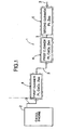
- FIG. 1 is a diagram for explaining an NOx clean-up system.
- FIG. 2 is a diagram for explaining an experimental NOx clean-up system.
- FIG. 3 is a sectional view of an essential part of Example (1) of a first cleaner.
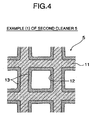
- FIG. 4 is a sectional view of an essential part of Example (1) of a second cleaner.
- FIG. 5 is a sectional view of an essential part of Example (2) of the first cleaner.
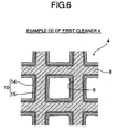
- FIG. 6 is a sectional view of an essential part of Example (3) of the first cleaner.
- An exhaust
emission control system 1 shown in FIG. 1 includes, in anexhaust pipe 3 of adiesel engine 2, twofirst cleaners 4 and asecond cleaner 5 installed sequentially from thediesel engine 2 side. One of thefirst cleaners 4 is disposed immediately below thediesel engine 2, and the otherfirst cleaner 4 and thesecond cleaner 5 are disposed beneath a vehicle floor. Either of the twofirst cleaners 4 may be omitted. - Each
first cleaner 4 includes Pt particles having an average particle size d1 of ≤ 10 nm, CeO2, and a zeolite (Zeo). It is not desirable for the average particle size d1 of the Pt particles to be greater than 10 nm, since the maximum temperature at which cleaning up of NOx is conducted shifts toward the exhaust gas high temperature region side, whereas the lower limit value for the average particle size d1 of the Pt particles is preferably 3 nm. If d1 is < 3 nm, the NOx clean-up temperature range tends to become narrow. - The Pt particles are supported on an SiO2Al2O3 support. Examples of the zeolite used include β zeolite, ZSM-5 zeolite, Y zeolite, and mordenite. As the other components, TiO2 is used for the purpose of improving the durability against sulfate, if necessary. These components are attached in the form of layers, together with a binder, to an inner face of each cell of a ceramic honeycomb support, thus forming a washcoat. Examples of the binder include alumina and silica.
- The content of each component of the washcoat is set as follows.
- Amount of Pt added a: 2.5 g/L ≤ a ≤ 4 g/L; it is undesirable if a < 2.5 g/L since the number of active sites decreases and sufficient NOx clean-up performance cannot be achieved, whereas it is undesirable if a > 4 g/L since the NOx clean-up performance saturates.
- SiO2-Al2O3 content b: 50 g/L ≤ b ≤ 90 g/L; if b < 50 g/L, the area of contact with exhaust gas becomes small, whereas if b > 90 g/L, since the Pt concentration is diluted, the NOx clean-up rate decreases.
- CeO2 content c: 15 g/L ≤ c ≤ 25 g/L; if c < 15 g/L, since the amount of NOx adsorbed decreases, cleaning up of NOx in the exhaust gas low temperature region is insufficient, whereas if c > 25 g/L, the NOx clean-up rate tends to decrease.
- Zeolite content d: 35 g/L ≤ d ≤ 65 g/L; it is undesirable if d < 35 g/L since adsorption of HC which is necessary for cleaning up NOx, cannot be carried out efficiently, whereas it is undesirable if d > 65 g/L since the Pt concentration is diluted. When a plurality of zeolites are used, the content of each zeolite is set in the above range.
- TiO2 content e: 3.5 g/L ≤ e ≤ 6.5 g/L; it is undesirable if e < 3.5 g/L since an effect of suppressing sulfur cannot be obtained and thus the NOx clean-up performance is degraded, whereas it is undesirable if e > 6.5 g/L since the effect of suppressing sulfur saturates.
- The
second cleaner 5 includes Pt particles having an average particle size d2 of ≥ 15 nm and a zeolite (Zeo). It is undesirable if the average particle size d2 of the Pt particles is < 15 nm, since the maximum temperature at which cleaning up of NOx is conducted shifts toward the exhaust gas low temperature region side. It is preferable for the upper limit value of the average particle size d2 of the Pt particles to be 30 nm. If d2 > 30 nm, the NOx clean-up rate tends to decrease accompanying a decrease in the specific surface area of the Pt particles. - The Pt particles are supported on an SiO2-Al2O3 support. Examples of the zeolite used include β zeolite, ZSM-5 zeolite, Y zeolite, and mordenite. As the other components, TiO2 is used for the purpose of improving the durability against sulfate, if necessary. These components are attached in the form of layers, together with a binder, to an inner face of each cell of a ceramic honeycomb support, thus forming a washcoat. Examples of the binder include alumina and silica.
- The content of each component of the washcoat is set as follows.
- Amount of Pt added a: 1.3 g/L ≤ a ≤ 2.5 g/L; it is undesirable if a < 1.3 g/L since the number of active sites decreases and sufficient NOx clean-up performance cannot be achieved, whereas it is undesirable if a > 2.5 g/L since the NOx clean-up performance saturates.
- SiO2-Al2O3 content b: 40 g/L ≤ b ≤ 65 g/L; if b < 40 g/L, the area of contact with exhaust gas becomes small, whereas if b > 65 g/L, since the Pt concentration is diluted, the NOx clean-up rate decreases.
- Zeolite content d: 55 g/L ≤ d ≤ 85 g/L; it is undesirable if d < 55 g/L since adsorption of HC which is necessary for cleaning up NOx, cannot be carried out efficiently, whereas it is undesirable if d > 85 g/L since the Pt concentration is diluted.
- TiO2 content e: 3.5 g/L ≤ e ≤ 6.5 g/L; it is undesirable if e < 3.5 g/L since the effect of suppressing sulfur cannot be obtained and the NOx clean-up performance is degraded, whereas it is undesirable if e > 6.5 g/L since the effect of suppressing sulfur saturates.
- Specific examples are explained below.
- As shown in FIG. 2, an experimental NOx clean-
up system 1 is equipped with a modelgas supply source 6, which corresponds to thediesel engine 2. Afirst cleaner 4 or a first comparison cleaner is installed on the upstream side of anexhaust pipe 3 extending from the modelgas supply source 6. Asecond cleaner 5 or a second comparison cleaner is installed on the downstream side. An NOx gauge 7 is connected to the exit of theexhaust pipe 3. - Assuming the case of exhaust gas of a diesel engine, the following model gas was prepared. Model gas: NO 160 ppm; HC 420 ppm C; CO 1100 ppm; CO2 3.6%;
O 2 15%; H2O 35%; balance N2. - As shown in FIG. 3, in Example (1) of the
first cleaner 4, the inner face of eachcell 9 of ahoneycomb support 8 had a washcoat 10 with a single layer structure. The average particle size d1 of Pt particles was 10 nm, and each component of thewashcoat 10 and the content thereof were as follows. Amount of Pt added a: 3.2 g/L; SiO2-Al2O3 content b: 71.8 g/L; CeO2 content c: 20 g/L; β zeolite content d: 50 g/L; ZSM-5 zeolite content d: 50 g/L; TiO2 content e: 5 g/L. - For comparison, a first comparison cleaner was prepared that had the same arrangement as that of Example (1) of the
first cleaner 4, except that it contained no CeO2. - As shown in FIG. 4, in Example (1) of the
second cleaner 5, the inner face of eachcell 12 of ahoneycomb support 11 had a washcoat 13 with a single layer structure. The average particle size d2 of Pt particles was 15 nm, and each component of thewashcoat 13 and the content thereof were as follows. Amount of Pt added a: 1.9 g/L; SiO2-Al2O3 content b: 53.1 g/L; β zeolite content d: 70 g/L; TiO2 content e: 5 g/L. - For comparison, a second comparison cleaner was prepared that had the same arrangement as that of Example (1) of the
second cleaner 5, except that the average particle size d2 of Pt particles was set at 10 nm. - As shown in Table 1, Example-A of the experimental
NOx control system 1 was a combination of Example (1) of thefirst cleaner 4 and Example (1) of thesecond cleaner 5; Example-B was a combination of the first and second comparison cleaners; and Example-C was a combination of Example (1) of thefirst cleaner 4 and the second comparison cleaner. In Example-A to Example-C, while increasing the temperature of the model gas in the modelgas supply source 6 at a temperature increase rate of 20°C/min from room temperature to 300°C, the model gas was passed through theexhaust pipe 3 at a space velocity SV of 50,000/h, and the average NOx clean-up rate of the model gas at temperatures of 50°C to 300°C was measured by the NOx gauge 7.Table 1 Experimental NOx control system Average NOx clean-up rate Example-A Example (1) of first cleaner Pt (d1): 10 nm; with CeO2 Example (1) of second cleaner Pt (d2): 15 nm 24% Example-B First comparison cleaner Pt (d1): 10 nm; without CeO2 Second comparison cleaner Pt (d2): 10 nm 15% Example-C Example (1) of first cleaner Pt (d1): 10 nm; with CeO2 Second comparison cleaner Pt (d2): 10 nm 15% - As is clear from Table 1, in Example-A, in the low exhaust gas temperature region the Pt particles of Example (1) of the
first cleaner 4 exhibited catalytic activity so as to clean up the NOx, and the CeO2 adsorbed NOx, whereas in the high exhaust gas temperature region the Pt particles of Example (1) of thesecond cleaner 5 exhibited catalytic activity so as to clean up the NOx in the exhaust gas and the NOx released from the CeO2, thus giving a high average NOx clean-up rate. - In Example-B, since NOx could not be adsorbed at all in the low exhaust gas temperature region, and cleaning up of NOx was insufficient in the high exhaust gas temperature region, the average NOx clean-up rate was lower than that of Example-A. In Example-C, although cleaning up of the NOx was good in the low exhaust gas temperature region, cleaning up of the NOx was insufficient in the high exhaust gas temperature region, and thus the average NOx clean-up rate was lower than that of Example-A.
- Example (2) of the
first cleaner 4 shown in FIG. 5 had a washcoat 10 having a two layer structure on the inner face of eachcell 9 of thehoneycomb support 8. The average particle size d1 of the Pt particles was 10 nm, and each component and the content thereof in afirst layer 14 which was on the inside in thewashcoat 10 were as follows. Amount of Pt added a: 3.2 g/L; SiO2-Al2O3 content b: 71.8 g/L; β zeolite content d: 50 g/L; TiO2 content e: 5 g/L. Each component and the content thereof in asecond layer 15 which was on the outside in thewashcoat 10 were as follows. CeO2 content c: 20 g/L; ZSM-5 zeolite content d: 50 g/L. - Example (3) of the
first cleaner 4 shown in FIG. 6 had an arrangement in which thefirst layer 14 of Example (2) was placed on the outside and thesecond layer 15 was placed on the inside. - That is, in Example (1) of the
first cleaner 4 shown in FIG. 3 the CeO2 was in a mixed state, in Example (2) of thefirst cleaner 4 shown in FIG. 5 the CeO2 was on the outside, and in Example (3) of thefirst cleaner 4 shown in FIG. 6 the CeO2 was on the inside. - As shown in Table 2, Example-D of the experimental
NOx control system 1 was a combination of Example (2) of thefirst cleaner 4 and Example (1) of thesecond cleaner 5; and Example-E was a combination of Example (3) of thefirst cleaner 4 and Example (1) of thesecond cleaner 5. In Example-D and Example-E, while increasing the temperature of the model gas in the modelgas supply source 6 at a temperature increase rate of 20°C/min from room temperature to 300°C, the model gas was passed through theexhaust pipe 3 at a space velocity SV of 50,000/h, and the average NOx clean-up rate of the model gas at temperatures from 50°C to 300°C was measured by the NOx gauge 7. Table 2 includes data related to Example-A for comparison purposes.Table 2 Experimental NOx control system Average NOx clean-up rate Example-A Example (1) of first cleaner CeO2: in mixed state Example (1) of second cleaner 24% Example-D Example (2) of first cleaner CeO2: on outside 21% Example-E Example (3) of first cleaner CeO2: on inside 29% - From Table 2, it was found that, when CeO2 was placed on the inside as shown in FIG. 6, the average NOx clean-up rate was the highest. It is surmised that NOx released from the CeO2 is cleaned by the Pt particles disposed on the outside and the β zeolite in cooperation.
- Example (4) of the
first cleaner 4 was prepared in the same manner as in the case of Example (3) of thefirst cleaner 4, except that the average particle size d1 of the Pt particles was changed to 5 nm in Example (3) of thefirst cleaner 4 shown in FIG. 6, that is, one in which CeO2 was placed on the inside. Similarly, Example (5) of thefirst cleaner 4 was prepared in the same manner as in the case of Example (3) of thefirst cleaner 4, except that the average particle size d1 of the Pt particles was changed to 3 nm. - Example (2) of the
second cleaner 5 was prepared in the same manner as in the case of Example (1) of thesecond cleaner 5, except that the average particle size d2 of the Pt particles was changed to 20 nm in Example (1) of thesecond cleaner 5 shown in FIG. 4. Similarly, Example (3) of thesecond cleaner 5 was prepared in the same manner as in the case of Example (1) of thesecond cleaner 5, except that the average particle size d2 of the Pt particles was changed to 30 nm. Similarly, Example (4) of thesecond cleaner 5 was prepared in the same manner as in the case of Example (1) of thesecond cleaner 5, except that the average particle size d2 of the Pt particles was changed to 50 nm. - As shown in Table 3, Example-F of the experimental
NOx control system 1 was a combination of Example (4) of thefirst cleaner 4 and Example (1) of thesecond cleaner 5; Example-G was a combination of Example (5) of thefirst cleaner 4 and Example (1) of thesecond cleaner 5; Example-H was a combination of Example (3) of thefirst cleaner 4 and Example (2) of thesecond cleaner 5; Example-I was a combination of Example (3) of thefirst cleaner 4 and Example (3) of thesecond cleaner 5; and Example-J was a combination of Example (3) of thefirst cleaner 4 and Example (4) of thesecond cleaner 5. - In Example-F to Example-J, while increasing the temperature of the model gas in the model
gas supply source 6 at a temperature increase rate of 20°C/min from room temperature to 300°C, the model gas was passed through theexhaust pipe 3 at a space velocity SV of 50,000/h, and the average NOx clean-up rate of the model gas at temperatures from 50°C to 300°C was measured by the NOx gauge 7. Table 3 includes the data related to Example-E for comparison purposes.Table 3 Experimental NOx control system Average NOx clean-up rate Example-E Example (3) of first cleaner Pt(d1):10nm Example (1) of second cleaner Pt (d2): 15 nm 29% Example-F Example (4) of first cleaner Pt (d1): 5 nm 32% Example-G Example (5) of first cleaner Pt (d1): 3 nm 31% Example-H Example (3) of first cleaner Pt(d1): 10 nm Example (2) of second cleaner Pt(d2): 20 nm 33% Example-I Example (3) of second cleaner Pt (d2): 30 nm 29% Example-J Example (4) of second cleaner Pt (d2): 50 nm 26% - It can be seen from Table 3 that, in order to improve the average NOx clean-up rate, the average particle size d1 of the Pt particles in the
first cleaner 4 is preferably 3 nm ≤ d1 ≤ 10 nm and the average particle size d2 of the Pt particles in thesecond cleaner 5 is preferably 15 nm ≤ d2 ≤ 30 nm. In thefirst cleaner 4, if the average particle size d1 of the Pt particles is too small, the NOx clean-up temperature range becomes small, whereas in thesecond cleaner 5 if the average particle size d2 of the Pt particles is too large, the average NOx clean-up rate decreases accompanying a decrease in the specific surface area. - Example (6) of the
first cleaner 4 was prepared in the same manner as in the case of Example (4) of thefirst cleaner 4, except that the CeO2 content c was changed to 10 g/L from Example (4) of thefirst cleaner 4 shown in FIG. 6, that is, one in which CeO2 was disposed on the inside and the CeO2 content c was set at 20 g/L. Similarly, Example (7) of thefirst cleaner 4 was prepared in the same manner as in the case of Example (4) of thefirst cleaner 4, except that the CeO2 content c was changed to 15 g/L. Similarly, Example (8) of thefirst cleaner 4 was prepared in the same manner as in the case of Example (4) of thefirst cleaner 4, except that the CeO2 content c was changed to 25 g/L. Similarly, Example (9) of thefirst cleaner 4 was prepared in the same manner as in the case of Example (4) of thefirst cleaner 4, except that the CeO2 content c was changed to 30 g/L. - As shown in Table 4, Example-K of the experimental
NOx control system 1 was a combination of Example (6) of thefirst cleaner 4 and Example (1) of thesecond cleaner 5; Example-L was a combination of Example (7) of thefirst cleaner 4 and Example (1) of thesecond cleaner 5; Example-M was a combination of Example (8) of thefirst cleaner 4 and Example (1) of thesecond cleaner 5; and Example-N was a combination of Example (9) of thefirst cleaner 4 and Example (1) of thesecond cleaner 5. - In Example-K to Example-N, while increasing the temperature of the model gas in the model
gas supply source 6 at a temperature increase rate of 20°C/min from room temperature to 300°C, the model gas was passed through theexhaust pipe 3 at a space velocity SV of 50,000/h, and the average NOx clean-up rate of the model gas at temperatures from 50°C to 300°C was measured by the NOx gauge 7. Table 4 includes data related to Example-F for comparison purposes.Table 4 Experimental NOx control system Average NOx clean-up rate Example-K Example (6) of first cleaner CeO2 content c: 10 g/L Example (1) of second cleaner 19% Example-L Example (7) of first cleaner CeO2 content c: 15 g/L 25% Example-F Example (4) of first cleaner CeO2 content c: 20 g/L 32% Example-M Example (8) of first cleaner CeO2 content c: 25 g/L 27% Example-N Example (9) of first cleaner CeO2 content c: 30 g/L 20% - It can be seen from Table 4 that, in order to improve the average NOx clean-up rate, the CeO2 content c is preferably 15 g/L ≤ c ≤ 25 g/L. When the CeO2 content is too small, the amount of NOx adsorbed is small, and cleaning up of NOx is insufficient in the low exhaust gas temperature region; when it is too large, the average NOx clean-up rate tends to decrease.
- A diesel engine exhaust emission control system includes, in an
exhaust pipe 3 of adiesel engine 2, afirst cleaner 4 and asecond cleaner 5 installed sequentially from thediesel engine 2 side. Thefirst cleaner 4 includes Pt particles having an average particle size d1 of ≤ 10 nm, CeO2, and a zeolite. Thesecond cleaner 5 includes Pt particles having an average particle size d2 of ≥ 15 nm, and a zeolite. Thus, it is possible to sufficiently clean up NOx throughout the entire exhaust gas temperature region.
Claims (2)
- A diesel engine exhaust emission control system comprising, in an exhaust pipe (3) of a diesel engine (2):a first cleaner (4) comprising Pt particles having an average particle size d1 of ≤ 10 nm, and a zeolite; anda second cleaner (5) comprising Pt particles having an average particle size d2 of ≥ 15 nm, and a zeolite;the first cleaner (4) and the second cleaner (5) being installed sequentially from the diesel engine (2) side,characterized in that
the first cleaner (4) comprises CeO2,
the first cleaner (4) being formed as a washcoat (10) on a face of a support,
the washcoat having a two layer structure with the CeO2 being placed in the inside layer. - A diesel engine exhaust emission control system according to claim 1,
wherein the first cleaner (4) and/or the second cleaner (5) comprises TiO2.
Applications Claiming Priority (2)
| Application Number | Priority Date | Filing Date | Title |
|---|---|---|---|
| JP2003433302A JP2005186002A (en) | 2003-12-26 | 2003-12-26 | Exhaust gas decontamination apparatus for diesel engine |
| JP2003433302 | 2003-12-26 |
Publications (2)
| Publication Number | Publication Date |
|---|---|
| EP1547682A1 EP1547682A1 (en) | 2005-06-29 |
| EP1547682B1 true EP1547682B1 (en) | 2006-08-09 |
Family
ID=34545074
Family Applications (1)
| Application Number | Title | Priority Date | Filing Date |
|---|---|---|---|
| EP04030356A Expired - Lifetime EP1547682B1 (en) | 2003-12-26 | 2004-12-21 | Diesel engine exhaust emission control system |
Country Status (3)
| Country | Link |
|---|---|
| EP (1) | EP1547682B1 (en) |
| JP (1) | JP2005186002A (en) |
| DE (1) | DE602004001844T8 (en) |
Families Citing this family (6)
| Publication number | Priority date | Publication date | Assignee | Title |
|---|---|---|---|---|
| JP4826207B2 (en) * | 2005-10-28 | 2011-11-30 | 日産自動車株式会社 | Exhaust gas purification catalyst and method for producing exhaust gas purification catalyst |
| JP2011177647A (en) * | 2010-03-01 | 2011-09-15 | Asahi Kasei Corp | Compound monolithic catalyst for nox removal in lean burn automobile exhaust gas |
| GB201021887D0 (en) * | 2010-12-21 | 2011-02-02 | Johnson Matthey Plc | Oxidation catalyst for a lean burn internal combustion engine |
| JP5310767B2 (en) * | 2011-03-29 | 2013-10-09 | トヨタ自動車株式会社 | Exhaust gas purification catalyst |
| EP3782727A1 (en) | 2019-08-20 | 2021-02-24 | Umicore Ag & Co. Kg | Ammonia emissions reduction catalyst |
| JP7635806B1 (en) | 2023-08-30 | 2025-02-26 | いすゞ自動車株式会社 | Exhaust purification system |
Family Cites Families (3)
| Publication number | Priority date | Publication date | Assignee | Title |
|---|---|---|---|---|
| JPH09103651A (en) * | 1995-10-11 | 1997-04-22 | Toyota Central Res & Dev Lab Inc | Exhaust gas purification device and exhaust gas purification method |
| JPH11138007A (en) * | 1997-11-06 | 1999-05-25 | Honda Motor Co Ltd | Composite catalyst for exhaust gas purification |
| EP1184556A3 (en) * | 2000-09-04 | 2004-01-02 | Nissan Motor Co., Ltd. | Engine exhaust emission purifier |
-
2003
- 2003-12-26 JP JP2003433302A patent/JP2005186002A/en not_active Ceased
-
2004
- 2004-12-21 EP EP04030356A patent/EP1547682B1/en not_active Expired - Lifetime
- 2004-12-21 DE DE602004001844T patent/DE602004001844T8/en active Active
Also Published As
| Publication number | Publication date |
|---|---|
| JP2005186002A (en) | 2005-07-14 |
| DE602004001844T2 (en) | 2006-12-07 |
| DE602004001844T8 (en) | 2007-03-29 |
| DE602004001844D1 (en) | 2006-09-21 |
| EP1547682A1 (en) | 2005-06-29 |
Similar Documents
| Publication | Publication Date | Title |
|---|---|---|
| EP1371415B1 (en) | Catalyst for hydrogen generation and catalyst for purification of exhaust gas | |
| KR101909303B1 (en) | Apparatus for treating exhaust gas of lean burn internal combustion engine comprising oxidation catalyst and method for recovering the oxidation activity of an oxidation catalyst | |
| CN101069833B (en) | Hydrocarbon adsorbent, catalyst for treating exhaust gas and method for purifying exhaust gas | |
| US7662743B2 (en) | NOx purifying catalyst | |
| US5677258A (en) | Burned gas purifying catalyst | |
| KR102268414B1 (en) | Emissions treatment system with ammonia-generating and scr catalysts | |
| EP1660217B1 (en) | Catalyst arrangement and method of purifying the exhaust gas of internal combustion engines operated under lean conditions | |
| EP2714247B1 (en) | Exhaust gas oxidation catalyst | |
| JP2015536236A (en) | Catalyzed soot filter for treating exhaust gas from compression ignition engines | |
| EP0993861B1 (en) | Catalyst for purifying exhaust gas from lean-burn engine | |
| EP2692436B1 (en) | Exhaust gas purification catalyst | |
| US12415178B2 (en) | Ammonia oxidation catalyst device | |
| US6893997B2 (en) | Exhaust gas purifying catalyst and method for purifying exhaust gas | |
| KR20070046164A (en) | Exhaust gas purification catalyst | |
| JP2008240568A (en) | Exhaust gas purification device | |
| KR100774577B1 (en) | Catalyst for purifying diesel engine exhaust gas and method for production thereof | |
| EP1547682B1 (en) | Diesel engine exhaust emission control system | |
| US20090317307A1 (en) | Exhaust gas purifying device | |
| US20030129098A1 (en) | Internal combustion engine exhaust gas purification device | |
| US9144789B2 (en) | Diesel exhaust gas purification catalyst and diesel exhaust gas purification system | |
| US20230149907A1 (en) | Exhaust gas purification catalyst device | |
| EP1310290B1 (en) | Purification catalyst for exhaust gas | |
| EP0922485B1 (en) | Combustion engine exhaust purifying catalyst | |
| JP3407901B2 (en) | Exhaust gas purifying catalyst, method for producing the catalyst, and method for purifying exhaust gas | |
| EP1961482A1 (en) | Catalyst carrier |
Legal Events
| Date | Code | Title | Description |
|---|---|---|---|
| PUAI | Public reference made under article 153(3) epc to a published international application that has entered the european phase |
Free format text: ORIGINAL CODE: 0009012 |
|
| 17P | Request for examination filed |
Effective date: 20050412 |
|
| AK | Designated contracting states |
Kind code of ref document: A1 Designated state(s): AT BE BG CH CY CZ DE DK EE ES FI FR GB GR HU IE IS IT LI LT LU MC NL PL PT RO SE SI SK TR |
|
| AX | Request for extension of the european patent |
Extension state: AL BA HR LV MK YU |
|
| GRAP | Despatch of communication of intention to grant a patent |
Free format text: ORIGINAL CODE: EPIDOSNIGR1 |
|
| AKX | Designation fees paid |
Designated state(s): DE GB |
|
| GRAS | Grant fee paid |
Free format text: ORIGINAL CODE: EPIDOSNIGR3 |
|
| GRAA | (expected) grant |
Free format text: ORIGINAL CODE: 0009210 |
|
| AK | Designated contracting states |
Kind code of ref document: B1 Designated state(s): DE GB |
|
| REG | Reference to a national code |
Ref country code: GB Ref legal event code: FG4D |
|
| REF | Corresponds to: |
Ref document number: 602004001844 Country of ref document: DE Date of ref document: 20060921 Kind code of ref document: P |
|
| PLBE | No opposition filed within time limit |
Free format text: ORIGINAL CODE: 0009261 |
|
| STAA | Information on the status of an ep patent application or granted ep patent |
Free format text: STATUS: NO OPPOSITION FILED WITHIN TIME LIMIT |
|
| 26N | No opposition filed |
Effective date: 20070510 |
|
| PGFP | Annual fee paid to national office [announced via postgrant information from national office to epo] |
Ref country code: GB Payment date: 20101215 Year of fee payment: 7 |
|
| PGFP | Annual fee paid to national office [announced via postgrant information from national office to epo] |
Ref country code: DE Payment date: 20101215 Year of fee payment: 7 |
|
| GBPC | Gb: european patent ceased through non-payment of renewal fee |
Effective date: 20111221 |
|
| REG | Reference to a national code |
Ref country code: DE Ref legal event code: R119 Ref document number: 602004001844 Country of ref document: DE Effective date: 20120703 |
|
| PG25 | Lapsed in a contracting state [announced via postgrant information from national office to epo] |
Ref country code: DE Free format text: LAPSE BECAUSE OF NON-PAYMENT OF DUE FEES Effective date: 20120703 Ref country code: GB Free format text: LAPSE BECAUSE OF NON-PAYMENT OF DUE FEES Effective date: 20111221 |