EP1547185B1 - Brennstoffzellenluftströmungsregulationsverfahren - Google Patents
Brennstoffzellenluftströmungsregulationsverfahren Download PDFInfo
- Publication number
- EP1547185B1 EP1547185B1 EP03798954A EP03798954A EP1547185B1 EP 1547185 B1 EP1547185 B1 EP 1547185B1 EP 03798954 A EP03798954 A EP 03798954A EP 03798954 A EP03798954 A EP 03798954A EP 1547185 B1 EP1547185 B1 EP 1547185B1
- Authority
- EP
- European Patent Office
- Prior art keywords
- air
- cathode
- fuel cell
- oxygen
- cathodic
- Prior art date
- Legal status (The legal status is an assumption and is not a legal conclusion. Google has not performed a legal analysis and makes no representation as to the accuracy of the status listed.)
- Expired - Lifetime
Links
- 239000000446 fuel Substances 0.000 title claims abstract description 48
- 238000000034 method Methods 0.000 title claims abstract description 17
- QVGXLLKOCUKJST-UHFFFAOYSA-N atomic oxygen Chemical compound [O] QVGXLLKOCUKJST-UHFFFAOYSA-N 0.000 claims abstract description 39
- 239000001301 oxygen Substances 0.000 claims abstract description 39
- 229910052760 oxygen Inorganic materials 0.000 claims abstract description 39
- 230000001105 regulatory effect Effects 0.000 claims abstract description 16
- 239000007789 gas Substances 0.000 claims abstract description 8
- 230000001276 controlling effect Effects 0.000 claims abstract 2
- 238000009434 installation Methods 0.000 claims description 9
- 239000000523 sample Substances 0.000 claims description 9
- 230000006835 compression Effects 0.000 claims description 3
- 238000007906 compression Methods 0.000 claims description 3
- 238000005259 measurement Methods 0.000 claims description 3
- 238000011144 upstream manufacturing Methods 0.000 claims description 2
- 239000003570 air Substances 0.000 description 76
- 239000001257 hydrogen Substances 0.000 description 9
- 229910052739 hydrogen Inorganic materials 0.000 description 9
- 239000007800 oxidant agent Substances 0.000 description 9
- 150000002431 hydrogen Chemical class 0.000 description 7
- 230000001590 oxidative effect Effects 0.000 description 7
- 239000012080 ambient air Substances 0.000 description 5
- 239000004215 Carbon black (E152) Substances 0.000 description 3
- 230000006870 function Effects 0.000 description 3
- 229930195733 hydrocarbon Natural products 0.000 description 3
- 150000002430 hydrocarbons Chemical class 0.000 description 3
- UFHFLCQGNIYNRP-UHFFFAOYSA-N Hydrogen Chemical compound [H][H] UFHFLCQGNIYNRP-UHFFFAOYSA-N 0.000 description 2
- 230000005611 electricity Effects 0.000 description 2
- 239000003792 electrolyte Substances 0.000 description 2
- 238000007254 oxidation reaction Methods 0.000 description 2
- 238000006722 reduction reaction Methods 0.000 description 2
- 238000006243 chemical reaction Methods 0.000 description 1
- 238000002485 combustion reaction Methods 0.000 description 1
- 239000004020 conductor Substances 0.000 description 1
- 238000001514 detection method Methods 0.000 description 1
- 238000000605 extraction Methods 0.000 description 1
- -1 gasoline Chemical class 0.000 description 1
- 239000005518 polymer electrolyte Substances 0.000 description 1
- 229920005597 polymer membrane Polymers 0.000 description 1
- 238000010248 power generation Methods 0.000 description 1
- 238000006479 redox reaction Methods 0.000 description 1
- 239000007784 solid electrolyte Substances 0.000 description 1
- 239000000126 substance Substances 0.000 description 1
- XLYOFNOQVPJJNP-UHFFFAOYSA-N water Substances O XLYOFNOQVPJJNP-UHFFFAOYSA-N 0.000 description 1
Images
Classifications
-
- H—ELECTRICITY
- H01—ELECTRIC ELEMENTS
- H01M—PROCESSES OR MEANS, e.g. BATTERIES, FOR THE DIRECT CONVERSION OF CHEMICAL ENERGY INTO ELECTRICAL ENERGY
- H01M8/00—Fuel cells; Manufacture thereof
- H01M8/04—Auxiliary arrangements, e.g. for control of pressure or for circulation of fluids
- H01M8/04082—Arrangements for control of reactant parameters, e.g. pressure or concentration
- H01M8/04089—Arrangements for control of reactant parameters, e.g. pressure or concentration of gaseous reactants
- H01M8/04104—Regulation of differential pressures
-
- Y—GENERAL TAGGING OF NEW TECHNOLOGICAL DEVELOPMENTS; GENERAL TAGGING OF CROSS-SECTIONAL TECHNOLOGIES SPANNING OVER SEVERAL SECTIONS OF THE IPC; TECHNICAL SUBJECTS COVERED BY FORMER USPC CROSS-REFERENCE ART COLLECTIONS [XRACs] AND DIGESTS
- Y02—TECHNOLOGIES OR APPLICATIONS FOR MITIGATION OR ADAPTATION AGAINST CLIMATE CHANGE
- Y02E—REDUCTION OF GREENHOUSE GAS [GHG] EMISSIONS, RELATED TO ENERGY GENERATION, TRANSMISSION OR DISTRIBUTION
- Y02E60/00—Enabling technologies; Technologies with a potential or indirect contribution to GHG emissions mitigation
- Y02E60/30—Hydrogen technology
- Y02E60/50—Fuel cells
Definitions
- the invention relates to a method of regulating the air flow admitted into the cathode of a fuel cell.
- the invention relates more particularly to a method of regulating the flow rate of air admitted into the cathode of a fuel cell which is on board a motor vehicle, of the type in which the fuel cell comprises a supply pipe.
- cathode which supplies the cathode with air, and in particular oxygen
- a cathodic evacuation pipe which evacuates the air after consumption of oxygen by the cathode
- the cathodic supply line comprises a controlled control member of the cathode, intake air flow, in particular according to the operating parameters of the engine.
- the fuel cells used to supply electrical energy on board motor vehicles are generally of the solid electrolyte type, in particular with polymer electrolyte.
- Such a cell uses in particular hydrogen (H 2 ) and oxygen (O 2 ) as fuel and oxidant respectively.
- the fuel cell offers the advantage of rejecting only the water produced by the engine. reduction reaction at the cathode.
- the oxidant of a battery of the type described above may be ambient air whose oxygen (O 2 ) is reduced.
- the electric power produced by the battery is proportional to the flow rates of oxidizer and fuel.
- the flow rates of air and hydrogen are generally predetermined according to the electrical power required for the vehicle.
- Patent Abstract of Japan vol. 0164, No. 01 discloses a fuel cell having a cathode supplied with air containing oxygen. He proposes to regulate the air admitted into the cathode by mixing it with a second gas rich in oxygen.
- One of the problems of this system is that the regulation of the air flow admitted into the cathode is not effective.
- DE 19,629,265 A further discloses a method for regulating the pressure of the gas admitted into the cathode of a fuel cell according to the electrical or thermal power that the fuel cell is to supply.
- the air flow rate and the oxygen content of the air are regulated so that the fuel cell provides a determined electrical power.
- One of the problems with this system is that the airflow is poorly regulated.
- the fuel cell consumes only the oxygen (O 2 ) contained in the air.
- the air is considered to have a substantially constant oxygen level.
- the amount of oxygen (O 2 ) present in the air varies according to the location of the vehicle.
- the air can be poorer in oxygen than on a country road.
- the air flow determined for an air containing a normal oxygen level does not allow a sufficient supply of oxygen from the fuel cell. combustible.
- the fuel cell can not provide the requested electrical power.
- the invention further relates to a device for regulating the air flow admitted into the cathode of a fuel cell which is carried on board a motor vehicle, of the type in which the fuel cell comprises a cathodic supply pipe which supplies the cathode with air, and in particular oxygen (O 2 ), and a cathodic evacuation pipe which discharges the air after consumption of oxygen (O 2 ) by the cathode, and wherein the cathodic supply line comprises a controlled member for regulating the intake air flow, in particular according to operating parameters of the engine characterized in that it is configured to measure the difference (O mes ) in oxygen concentration (O 2 ) between a reference gas and the air circulating in the cathodic evacuation pipe.
- the fuel cell comprises a cathodic supply pipe which supplies the cathode with air, and in particular oxygen (O 2 ), and a cathodic evacuation pipe which discharges the air after consumption of oxygen (O 2 ) by the cathode
- the cathodic supply line comprises a controlled
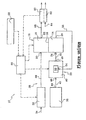
- the single figure shows a power generation installation 10 which is embedded in a motor vehicle.
- the installation 10 comprises in particular a fuel cell 12 which produces electricity when it is supplied with oxidant and fuel.
- the fuel cell 12 comprises an anode 14 and a cathode 16 which are here separated by an electrolyte polymer membrane 18.
- the cathode 16 has a cathode feed port 20 through which it is supplied with oxidant, which is air here, and it has a cathode discharge port 22 through which the excess oxidant is discharged.
- the anode 14 comprises an anode supply port 24 through which it is supplied with fuel, which is here a reformate including hydrogen (H 2 ), and has an anodic discharge port 26 through which excess fuel is discharged.
- fuel which is here a reformate including hydrogen (H 2 )
- anodic discharge port 26 through which excess fuel is discharged.
- the installation 10 comprises a first supply circuit 28 of the cathode 16 by combustion, and in particular air, and it comprises a second supply circuit 30 of the anode 14 with fuel, and in particular with hydrogen (H 2 ) .
- the first supply circuit 28 of the cathode 16 is composed in particular of an atmospheric air intake module 32 in which the atmospheric air is admitted via an inlet section 34, and which supplies the cathode 16 with air via a cathode supply line 36 which is connected to the cathode supply port 20.
- the air intake module 32 is in particular intended to regulate the flow rate of air admitted into the cathode 16.
- the air intake module 32 comprises, according to this embodiment of the invention, a compressor (not shown). .
- the air intake module 32 comprises a motor-fan which is arranged in the cathodic supply duct 36.
- the second feed circuit 30 of the anode 14 consists mainly of a reservoir 38 containing a hydrocarbon such as gasoline, and a reformer 40.
- a hydrocarbon feed pipe 42 is connected at a first end 44 to the tank 38 and at a second end to an inlet 46 of the reformer 40.
- the reformer 40 is here intended to extract the hydrogen (H 2 ) contained in the hydrocarbon. After extraction of the hydrogen (H 2 ), it discharges through an outlet 48 a fuel, or reformate, containing hydrogen (H 2 ) in a supply pipe 50 of the anode 14 which is connected to the anode supply port 24.
- the anode 14 consumes some of the hydrogen (H 2 ) contained in the reformate, the excess reformate being rejected by the anodic discharge port 26.
- the anode discharge port 26 opens into an anodic discharge pipe 52 which leads the excess reformate to a supply orifice 54 of a burner 56 which is integrated in the reformer 40.
- the burner 56 is particularly intended for consuming the excess reformate so as to provide the heat necessary for the operation of the reformer 40.
- the cathode 16 consumes a portion of the oxygen (O 2 ) contained in the air, the excess air being rejected by the cathodic discharge port 22.
- the discharge port of the cathode 16 opens into a cathode discharge line 58 which expels the excess air to the atmosphere.
- an oxygen detection probe 60 which is in this embodiment of the invention a lambda type probe, is interposed in the cathodic evacuation pipe 58.
- a reference portion 62 of the lambda probe 60 is in contact with the ambient air which is here conveyed by an air duct 64.
- the installation 10 also comprises an electronic control unit 66 which is intended to control the operation of the fuel cell 12.
- the electronic control unit 66 is in particular connected by electrical conductor wires, shown in broken lines in the single figure. at the lambda probe 60, the reformer 40, the air intake module 32 and a power control device 68 located in the passenger compartment of the vehicle and which may for example be an accelerator pedal.
- the electronic control unit 66 controls the intake module on the one hand and the reformer 40 on the other hand so as to provide oxidizer and fuel flow rates determined according to the power of the required electrical power.
- This method is intended to adjust the air flow as a function of its oxygen content when the driver requires electrical power to the fuel cell 12 for the vehicle engine.
- the fuel cell 12 is then fueled with fuel and oxidant and discharges through the anode and cathode evacuation ports excess reformate and air, respectively.
- the cathodic evacuation pipe 58 guides the air rejected by the cathodic evacuation orifice 22 to the lambda probe 60 after consumption of a part of its oxygen by the fuel cell 12 .
- the then lambda probe 60 transmits to the electronic control unit 66 an electrical signal which constitutes the measure O my of the difference in oxygen concentration between the atmospheric air and the air flowing in the cathodic discharge conduit 58.
- the electrical signal has an intensity proportional to the difference of oxygen concentration between the atmospheric air and the air circulating in the cathodic discharge pipe 58.
- the electronic control unit 66 subtracts the value of the measurement O mes emitted by the lambda probe 60 from a reference value O ref .
- the reference value O ref is entered into memory in the electronic control unit 66.
- the reference value O ref is here the theoretical value of the difference in oxygen concentration between the atmospheric air and the air circulating in the pipe. cathodic discharge 58 when the atmospheric air contains a normal proportion of oxygen, that is to say about 21%.
- the measured value O mes differs significantly from the reference value O ref .
- the electronic control unit 66 determines an optimal airflow from a map stored in memory according to the result of the subtraction (O mes - O ref ) performed during the second step E2.
- the optimum air flow rate is set so that the flow rate of oxygen passing through the fuel cell 12 is at least sufficient for the battery 12 to provide the electrical power required by the driver.
- the electronic control unit 66 controls the air intake module 32 so that the intake air flow rate is substantially equal to the optimal air flow rate.
- an alert signal is emitted in the passenger compartment of the vehicle to prevent the driver that the ambient air is too low in oxygen to be able to satisfactorily supply the fuel cell 12 even by increasing the air flow in the proportions allowed by the capacity of the air intake module 32.
- the operation of the fuel cell 12 is automatically interrupted by the unit of electronic control 66.
Landscapes
- Life Sciences & Earth Sciences (AREA)
- Engineering & Computer Science (AREA)
- Manufacturing & Machinery (AREA)
- Sustainable Development (AREA)
- Sustainable Energy (AREA)
- Chemical & Material Sciences (AREA)
- Chemical Kinetics & Catalysis (AREA)
- Electrochemistry (AREA)
- General Chemical & Material Sciences (AREA)
- Fuel Cell (AREA)
- Electric Propulsion And Braking For Vehicles (AREA)
- Regulation And Control Of Combustion (AREA)
- Fuel-Injection Apparatus (AREA)
- Feeding And Controlling Fuel (AREA)
Claims (7)
- Verfahren zur Regelung des Luftdurchsatzes, der in eine Kathode (16) einer Brennstoffzelle (12) eingelassen wird, die sich an Bord eines Kraftfahrzeugs befindet, von der Art, bei welcher die Brennstoffzelle (12) eine kathodische Versorgungsleitung (36) aufweist, welche die Kathode (16) mit Luft und insbesondere mit Sauerstoff (O2) versorgt, und eine kathodische Auslassleitung (58), welche die Luft nach Verbrauch des Sauerstoffs (O2) durch die Kathode (16) auslässt, und in welcher die kathodische Versorgungsleitung (36) ein gesteuertes Regelungsbauteil (32) des Einlassluftdurchsatzes aufweist, insbesondere in Abhängigkeit von Betriebsparametern des Motors,
dadurch gekennzeichnet, dass es aufweist:a) einen Schritt (E1) einer Messung des Konzentrationsunterschieds (Omes) an Sauerstoff (O2) zwischen einem Referenzgas und der Luft, die in der kathodischen Auslassleitung (58) strömt; undb) einen Schritt (E2) einer Berechnung des Unterschieds (Omes - Oref) zwischen dem gemessenen Wert (Omes) und einem Referenzwert (Oref); undc) einen Schritt (E3) einer Feststellung eines optimalen Durchsatzes an Einlassluft in Abhängigkeit von dem Ergebnis (Omes - Oref) der Berechnung; undd) einen Schritt (E4) einer Steuerung des Regelungsbauteils (32) für den Erhalt des optimalen Luftdurchsatzes. - Verfahren nach dem vorangegangenen Anspruch, dadurch gekennzeichnet, dass die Messung (Omes) des Messschritts (E1) mittels einer Lambdasonde (60) realisiert wird, welche in der kathodischen Auslassleitung (58) angeordnet ist und welche den Konzentrationsunterschied an sauerstoff zwischen der Umgebungsluft und der Luft, die in der kathodischen Auslassleitung (58) strömt, misst.
- Verfahren nach Anspruch 1, dadurch gekennzeichnet, dass das Regelungsbauteil (32) des Luftdurchsatzes eine Komprimierungseinrichtung der Luft ist, die stromaufwärts der Kathode (16) angeordnet ist.
- Verfahren nach Anspruch 1, dadurch gekennzeichnet, dass das Regelungsbauteil (32) des Luftdurchsatzes ein inotorgrtriebener Ventilator ist, der in der kathodischen Versorgungsleitung (36) angeordnet ist.
- Verfahren nach einem der Ansprüche 1 oder 2, dadurch gekennzeichnet, dass, wenn der gemessene Wert (Omes) niedriger als ein vorherbestimmter Schwellenwert ist, dann ein Warnsignal in die Fahrgastzelle ausgesendet wird.
- Verfahren nach dem vorangegangenen Anspruch, dadurch gekennzeichnet, dass, wenn der gemessene Wert (Omes) niedriger als ein vorherbestimmter Schwellenwert ist, der Betrieb der Brennstoffzelle (12) unterbrochen wird.
- Vorrichtung zur Regelung des Durchsatzes an Luft, die in die Kathode (16) einer Brennstoffzelle (12) eingelassen wird, welche sich an Bord eines Kraftfahrzeugs befindet, von der Art, bei welcher die Brennstoffzelle (12) eine kathodische Versorgungsleitung (36) aufweist, welche die Kathode (16) mit Luft und insbesondere mit Sauerstoff (O2) versorgt, und eine kathodische Auslassleitung (58), welche die Luft nach dem Verbrauch von Sauerstoff (O2) durch die Kathode (16) auslässt, und in welcher die kathodische Versorgungsleitung (36) ein gesteuertes Regelungsbauteil (32) des Durchsatzes an Einlassluft aufweist, insbesondere in Abhängigkeit von Betriebsparametern des Motors, dadurch gekennzeichnet, dass sie ausgestaltet ist, um den Konzentrationsunterschied (Omes) an Sauerstoff (O2) zwischen einem Referenzgas und der Luft zu messen, die in der kathodischen Auslassleitung (58) strömt.
Applications Claiming Priority (3)
| Application Number | Priority Date | Filing Date | Title |
|---|---|---|---|
| FR0212255A FR2845524B1 (fr) | 2002-10-03 | 2002-10-03 | Procede de regulation du debit d'air dans une pile a combustible |
| FR0212255 | 2002-10-03 | ||
| PCT/FR2003/002892 WO2004032268A2 (fr) | 2002-10-03 | 2003-10-02 | Procede de regulation du debit d'air dans une pile a combustible |
Publications (3)
| Publication Number | Publication Date |
|---|---|
| EP1547185A2 EP1547185A2 (de) | 2005-06-29 |
| EP1547185B1 true EP1547185B1 (de) | 2006-03-01 |
| EP1547185B8 EP1547185B8 (de) | 2006-05-17 |
Family
ID=32011367
Family Applications (1)
| Application Number | Title | Priority Date | Filing Date |
|---|---|---|---|
| EP03798954A Expired - Lifetime EP1547185B8 (de) | 2002-10-03 | 2003-10-02 | Brennstoffzellenluftströmungsregulationsverfahren |
Country Status (6)
| Country | Link |
|---|---|
| EP (1) | EP1547185B8 (de) |
| AT (1) | ATE319194T1 (de) |
| DE (1) | DE60303829T2 (de) |
| ES (1) | ES2254986T3 (de) |
| FR (1) | FR2845524B1 (de) |
| WO (1) | WO2004032268A2 (de) |
Family Cites Families (4)
| Publication number | Priority date | Publication date | Assignee | Title |
|---|---|---|---|---|
| JPH04133271A (ja) * | 1990-09-25 | 1992-05-07 | Nippon Telegr & Teleph Corp <Ntt> | 燃料電池 |
| DE19629265A1 (de) * | 1996-07-19 | 1998-01-22 | Siemens Ag | Verfahren und Anlage zur Leistungsanpassung einer Brennstoffzelle |
| JP2000251911A (ja) * | 1999-03-03 | 2000-09-14 | Nissan Motor Co Ltd | 燃料電池発電システム |
| EP1205993B1 (de) * | 2000-11-07 | 2012-12-05 | Hexis AG | Verfahren zur Betreiben einer Brennstoffzellenbatterie mit einer Steuerung |
-
2002
- 2002-10-03 FR FR0212255A patent/FR2845524B1/fr not_active Expired - Fee Related
-
2003
- 2003-10-02 EP EP03798954A patent/EP1547185B8/de not_active Expired - Lifetime
- 2003-10-02 WO PCT/FR2003/002892 patent/WO2004032268A2/fr not_active Ceased
- 2003-10-02 ES ES03798954T patent/ES2254986T3/es not_active Expired - Lifetime
- 2003-10-02 DE DE60303829T patent/DE60303829T2/de not_active Expired - Lifetime
- 2003-10-02 AT AT03798954T patent/ATE319194T1/de not_active IP Right Cessation
Also Published As
| Publication number | Publication date |
|---|---|
| FR2845524A1 (fr) | 2004-04-09 |
| ES2254986T3 (es) | 2006-06-16 |
| EP1547185A2 (de) | 2005-06-29 |
| WO2004032268A3 (fr) | 2005-03-03 |
| EP1547185B8 (de) | 2006-05-17 |
| FR2845524B1 (fr) | 2005-06-17 |
| WO2004032268A2 (fr) | 2004-04-15 |
| ATE319194T1 (de) | 2006-03-15 |
| DE60303829T2 (de) | 2006-08-31 |
| DE60303829D1 (de) | 2006-04-27 |
Similar Documents
| Publication | Publication Date | Title |
|---|---|---|
| EP1776730B1 (de) | Steuerung der polymer-befeuchtung der membran einer brennstoffzelle | |
| EP1339125A2 (de) | Kontrolle der Gasspülung von Anodenabgas einer Brennstoffzelle | |
| US6635373B2 (en) | Fuel cell system and method | |
| US7318971B2 (en) | Fuel cell system utilizing control of operating current to adjust moisture content within fuel cell | |
| FR2459885A1 (fr) | Systeme pour une commande a retro-action du rapport air/carburant dans un moteur a combustion interne | |
| JP2005327596A (ja) | 燃料電池システム | |
| JP2005100820A (ja) | 燃料電池システム | |
| US20220320553A1 (en) | Method of determining degradation of fuel cell stack, and fuel cell vehicle equipped with the fuel cell stack | |
| EP1547185B1 (de) | Brennstoffzellenluftströmungsregulationsverfahren | |
| JP7776625B2 (ja) | 空になった水分離器を自動で認識する燃料電池システム | |
| EP3340353B1 (de) | Elektrochemisches system mit brennstoffzelle, das eine vorrichtung zum einstellen des drucks mit expansionsventil umfasst | |
| EP1545915B1 (de) | Energierückgewinnungsverfahren und -vorrichtung, das bzw. die an bord eines fahrzeugs mit einer reformer-brennstoffzelle verwendet werden | |
| WO2010103400A1 (en) | Fuel cell system, control method for the fuel cell system, and state detection method for fuel cell | |
| FR2914786A1 (fr) | Procede d'evaluation des debits des gaz circulant dans une boucle de recirculation en hydrogene d'une cellule de pile a combustible et dispositif associe | |
| FR2845825A1 (fr) | Dispositif de recuperation d'eau dans une installation de production d'electricite comprenant une pile a combustible | |
| EP3340354B1 (de) | Elektrochemisches system mit brennstoffzelle, das eine vorrichtung zum einstellen des drucks mit expansionsventil umfasst | |
| FR2860646A1 (fr) | Dispositif de gestion de l'eau d'un systeme pile a combustible incluant un reformeur essence | |
| FR2862435A1 (fr) | Dispositif d'humidification cathodique et de gestion thermique d'un systeme pile a combustible | |
| EP1385224A1 (de) | Abgasrückführung von einem Reformer-Brenner in einem Brennstoffzellen-Abgas-Kreislauf | |
| CN119447375A (zh) | 水下设备、燃料电池系统及其吹扫方法 | |
| FR2880993A1 (fr) | Installation de production d'electricite comportant une pile a combustible dont l'anode est alimentee successivement par deux sources de carburant | |
| FR2861220A1 (fr) | Dispositif et procede de prechauffage d'un systeme pile a combustible | |
| JP2008072824A (ja) | 燃料電池車両 | |
| FR2883667A1 (fr) | Installation de production d'electricite a bord d'un vehicule automobile comprenant une pile a combustible | |
| FR2900502A1 (fr) | Dispositif et procede de commande du debit d'air pour pile a combustible |
Legal Events
| Date | Code | Title | Description |
|---|---|---|---|
| PUAI | Public reference made under article 153(3) epc to a published international application that has entered the european phase |
Free format text: ORIGINAL CODE: 0009012 |
|
| 17P | Request for examination filed |
Effective date: 20050210 |
|
| AK | Designated contracting states |
Kind code of ref document: A2 Designated state(s): AT BE BG CH CY CZ DE DK EE ES FI FR GB GR HU IE IT LI LU MC NL PT RO SE SI SK TR |
|
| GRAP | Despatch of communication of intention to grant a patent |
Free format text: ORIGINAL CODE: EPIDOSNIGR1 |
|
| GRAS | Grant fee paid |
Free format text: ORIGINAL CODE: EPIDOSNIGR3 |
|
| GRAA | (expected) grant |
Free format text: ORIGINAL CODE: 0009210 |
|
| AK | Designated contracting states |
Kind code of ref document: B1 Designated state(s): AT BE BG CH CY CZ DE DK EE ES FI FR GB GR HU IE IT LI LU MC NL PT RO SE SI SK TR |
|
| PG25 | Lapsed in a contracting state [announced via postgrant information from national office to epo] |
Ref country code: IT Free format text: LAPSE BECAUSE OF FAILURE TO SUBMIT A TRANSLATION OF THE DESCRIPTION OR TO PAY THE FEE WITHIN THE PRESCRIBED TIME-LIMIT;WARNING: LAPSES OF ITALIAN PATENTS WITH EFFECTIVE DATE BEFORE 2007 MAY HAVE OCCURRED AT ANY TIME BEFORE 2007. THE CORRECT EFFECTIVE DATE MAY BE DIFFERENT FROM THE ONE RECORDED. Effective date: 20060301 Ref country code: SK Free format text: LAPSE BECAUSE OF FAILURE TO SUBMIT A TRANSLATION OF THE DESCRIPTION OR TO PAY THE FEE WITHIN THE PRESCRIBED TIME-LIMIT Effective date: 20060301 Ref country code: FI Free format text: LAPSE BECAUSE OF FAILURE TO SUBMIT A TRANSLATION OF THE DESCRIPTION OR TO PAY THE FEE WITHIN THE PRESCRIBED TIME-LIMIT Effective date: 20060301 Ref country code: IE Free format text: LAPSE BECAUSE OF FAILURE TO SUBMIT A TRANSLATION OF THE DESCRIPTION OR TO PAY THE FEE WITHIN THE PRESCRIBED TIME-LIMIT Effective date: 20060301 Ref country code: SI Free format text: LAPSE BECAUSE OF FAILURE TO SUBMIT A TRANSLATION OF THE DESCRIPTION OR TO PAY THE FEE WITHIN THE PRESCRIBED TIME-LIMIT Effective date: 20060301 Ref country code: NL Free format text: LAPSE BECAUSE OF FAILURE TO SUBMIT A TRANSLATION OF THE DESCRIPTION OR TO PAY THE FEE WITHIN THE PRESCRIBED TIME-LIMIT Effective date: 20060301 Ref country code: AT Free format text: LAPSE BECAUSE OF FAILURE TO SUBMIT A TRANSLATION OF THE DESCRIPTION OR TO PAY THE FEE WITHIN THE PRESCRIBED TIME-LIMIT Effective date: 20060301 Ref country code: RO Free format text: LAPSE BECAUSE OF FAILURE TO SUBMIT A TRANSLATION OF THE DESCRIPTION OR TO PAY THE FEE WITHIN THE PRESCRIBED TIME-LIMIT Effective date: 20060301 |
|
| REG | Reference to a national code |
Ref country code: GB Ref legal event code: FG4D Free format text: NOT ENGLISH |
|
| REG | Reference to a national code |
Ref country code: CH Ref legal event code: EP |
|
| REG | Reference to a national code |
Ref country code: IE Ref legal event code: FG4D Free format text: LANGUAGE OF EP DOCUMENT: FRENCH |
|
| RBV | Designated contracting states (corrected) |
Designated state(s): AT BE BG CH CY CZ DE DK EE ES FI GB GR HU IE IT LI LU MC NL PT RO SE SI SK TR |
|
| GBT | Gb: translation of ep patent filed (gb section 77(6)(a)/1977) |
Effective date: 20060405 |
|
| REF | Corresponds to: |
Ref document number: 60303829 Country of ref document: DE Date of ref document: 20060427 Kind code of ref document: P |
|
| PG25 | Lapsed in a contracting state [announced via postgrant information from national office to epo] |
Ref country code: SE Free format text: LAPSE BECAUSE OF FAILURE TO SUBMIT A TRANSLATION OF THE DESCRIPTION OR TO PAY THE FEE WITHIN THE PRESCRIBED TIME-LIMIT Effective date: 20060601 Ref country code: DK Free format text: LAPSE BECAUSE OF FAILURE TO SUBMIT A TRANSLATION OF THE DESCRIPTION OR TO PAY THE FEE WITHIN THE PRESCRIBED TIME-LIMIT Effective date: 20060601 Ref country code: BG Free format text: LAPSE BECAUSE OF FAILURE TO SUBMIT A TRANSLATION OF THE DESCRIPTION OR TO PAY THE FEE WITHIN THE PRESCRIBED TIME-LIMIT Effective date: 20060601 |
|
| REG | Reference to a national code |
Ref country code: ES Ref legal event code: FG2A Ref document number: 2254986 Country of ref document: ES Kind code of ref document: T3 |
|
| PG25 | Lapsed in a contracting state [announced via postgrant information from national office to epo] |
Ref country code: PT Free format text: LAPSE BECAUSE OF FAILURE TO SUBMIT A TRANSLATION OF THE DESCRIPTION OR TO PAY THE FEE WITHIN THE PRESCRIBED TIME-LIMIT Effective date: 20060801 |
|
| NLV1 | Nl: lapsed or annulled due to failure to fulfill the requirements of art. 29p and 29m of the patents act | ||
| PG25 | Lapsed in a contracting state [announced via postgrant information from national office to epo] |
Ref country code: MC Free format text: LAPSE BECAUSE OF NON-PAYMENT OF DUE FEES Effective date: 20061031 |
|
| REG | Reference to a national code |
Ref country code: IE Ref legal event code: FD4D |
|
| PLBE | No opposition filed within time limit |
Free format text: ORIGINAL CODE: 0009261 |
|
| STAA | Information on the status of an ep patent application or granted ep patent |
Free format text: STATUS: NO OPPOSITION FILED WITHIN TIME LIMIT |
|
| 26N | No opposition filed |
Effective date: 20061204 |
|
| REG | Reference to a national code |
Ref country code: FR Ref legal event code: ST Effective date: 20070629 |
|
| PG25 | Lapsed in a contracting state [announced via postgrant information from national office to epo] |
Ref country code: CZ Free format text: LAPSE BECAUSE OF FAILURE TO SUBMIT A TRANSLATION OF THE DESCRIPTION OR TO PAY THE FEE WITHIN THE PRESCRIBED TIME-LIMIT Effective date: 20060301 Ref country code: GR Free format text: LAPSE BECAUSE OF FAILURE TO SUBMIT A TRANSLATION OF THE DESCRIPTION OR TO PAY THE FEE WITHIN THE PRESCRIBED TIME-LIMIT Effective date: 20060602 |
|
| REG | Reference to a national code |
Ref country code: CH Ref legal event code: PL |
|
| PG25 | Lapsed in a contracting state [announced via postgrant information from national office to epo] |
Ref country code: EE Free format text: LAPSE BECAUSE OF FAILURE TO SUBMIT A TRANSLATION OF THE DESCRIPTION OR TO PAY THE FEE WITHIN THE PRESCRIBED TIME-LIMIT Effective date: 20060301 |
|
| PG25 | Lapsed in a contracting state [announced via postgrant information from national office to epo] |
Ref country code: TR Free format text: LAPSE BECAUSE OF FAILURE TO SUBMIT A TRANSLATION OF THE DESCRIPTION OR TO PAY THE FEE WITHIN THE PRESCRIBED TIME-LIMIT Effective date: 20060301 Ref country code: CH Free format text: LAPSE BECAUSE OF NON-PAYMENT OF DUE FEES Effective date: 20071031 Ref country code: LU Free format text: LAPSE BECAUSE OF NON-PAYMENT OF DUE FEES Effective date: 20061002 Ref country code: HU Free format text: LAPSE BECAUSE OF FAILURE TO SUBMIT A TRANSLATION OF THE DESCRIPTION OR TO PAY THE FEE WITHIN THE PRESCRIBED TIME-LIMIT Effective date: 20060902 Ref country code: LI Free format text: LAPSE BECAUSE OF NON-PAYMENT OF DUE FEES Effective date: 20071031 |
|
| PG25 | Lapsed in a contracting state [announced via postgrant information from national office to epo] |
Ref country code: CY Free format text: LAPSE BECAUSE OF FAILURE TO SUBMIT A TRANSLATION OF THE DESCRIPTION OR TO PAY THE FEE WITHIN THE PRESCRIBED TIME-LIMIT Effective date: 20060301 |
|
| PGFP | Annual fee paid to national office [announced via postgrant information from national office to epo] |
Ref country code: DE Payment date: 20131021 Year of fee payment: 11 Ref country code: GB Payment date: 20131021 Year of fee payment: 11 Ref country code: BE Payment date: 20131022 Year of fee payment: 11 |
|
| PGFP | Annual fee paid to national office [announced via postgrant information from national office to epo] |
Ref country code: ES Payment date: 20131029 Year of fee payment: 11 Ref country code: IT Payment date: 20131028 Year of fee payment: 11 |
|
| REG | Reference to a national code |
Ref country code: DE Ref legal event code: R119 Ref document number: 60303829 Country of ref document: DE |
|
| GBPC | Gb: european patent ceased through non-payment of renewal fee |
Effective date: 20141002 |
|
| PG25 | Lapsed in a contracting state [announced via postgrant information from national office to epo] |
Ref country code: BE Free format text: LAPSE BECAUSE OF NON-PAYMENT OF DUE FEES Effective date: 20141031 |
|
| PG25 | Lapsed in a contracting state [announced via postgrant information from national office to epo] |
Ref country code: GB Free format text: LAPSE BECAUSE OF NON-PAYMENT OF DUE FEES Effective date: 20141002 Ref country code: DE Free format text: LAPSE BECAUSE OF NON-PAYMENT OF DUE FEES Effective date: 20150501 |
|
| PG25 | Lapsed in a contracting state [announced via postgrant information from national office to epo] |
Ref country code: IT Free format text: LAPSE BECAUSE OF NON-PAYMENT OF DUE FEES Effective date: 20141002 |
|
| REG | Reference to a national code |
Ref country code: ES Ref legal event code: FD2A Effective date: 20151127 |
|
| PG25 | Lapsed in a contracting state [announced via postgrant information from national office to epo] |
Ref country code: ES Free format text: LAPSE BECAUSE OF NON-PAYMENT OF DUE FEES Effective date: 20141003 |