EP1546897B1 - Bus connection system - Google Patents
Bus connection system Download PDFInfo
- Publication number
- EP1546897B1 EP1546897B1 EP03725545A EP03725545A EP1546897B1 EP 1546897 B1 EP1546897 B1 EP 1546897B1 EP 03725545 A EP03725545 A EP 03725545A EP 03725545 A EP03725545 A EP 03725545A EP 1546897 B1 EP1546897 B1 EP 1546897B1
- Authority
- EP
- European Patent Office
- Prior art keywords
- host
- station
- bus
- port
- usb
- Prior art date
- Legal status (The legal status is an assumption and is not a legal conclusion. Google has not performed a legal analysis and makes no representation as to the accuracy of the status listed.)
- Expired - Lifetime
Links
Images
Classifications
-
- G—PHYSICS
- G06—COMPUTING OR CALCULATING; COUNTING
- G06F—ELECTRIC DIGITAL DATA PROCESSING
- G06F13/00—Interconnection of, or transfer of information or other signals between, memories, input/output devices or central processing units
- G06F13/38—Information transfer, e.g. on bus
- G06F13/382—Information transfer, e.g. on bus using universal interface adapter
- G06F13/385—Information transfer, e.g. on bus using universal interface adapter for adaptation of a particular data processing system to different peripheral devices
Definitions
- This invention relates to a bus connection system, and in particular to a device which can be used with electronic equipment in a bus communication system to allow the equipment to act as a host within the system.
- USB Universal Serial Bus
- USB In a USB system, it is possible to interconnect many items of electronic equipment, such as personal computers, scanners, mobile phones, printers, etc. In any system, one item of equipment is always designated as the USB host, which controls connections with all of the other items, or USB devices. Personal computers are typically provided with the hardware and software required to allow them to act as USB hosts, but other items are typically not provided with the required hardware and software, and thus can only act as USB devices.
- US 5,784,581 discloses an apparatus, which can act as a USB slave device when a USB host is connected to a privileged port, or alternatively can act as a USB host to a slave device connected to a second port, when no USB host is connected to the privileged port.
- a bus station preferably in the form of a hardware dongle, which can be connected to the bus communication port of a bus communication device, enabling it to act as a bus host.
- the bus station operates in the USB system, although the invention is also applicable to other bus communication systems.
- one aspect of the present invention provides a bus station which, when it determines that a bus host is connected to a first bus communication port thereof, acts as a transceiver to allow conventional bus communications between said bus host and a bus device connected to a second bus communication port thereof; and which, when it determines that a bus device running suitable software is connected to the first bus communication port thereof, acts as an alternate host to allow bus communications between said bus device connected to the first bus communication port and a bus device connected to a second bus communication port.
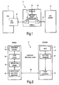
- Fig. 1 is a block schematic diagram of a bus communication system in accordance with the invention.
- the system 2 comprises a first USB Device 4 with a USB port 6, a second USB Device 8 and a dongle 10.
- the first USB Device 4 is a personal digital assistant (PDA), but it will be appreciated that the invention is applicable to any USB Device such as a mobile communications device, digital camera or a personal organizer.
- PDA personal digital assistant
- the second USB Device 8 may be any USB Device including a printer, mouse, hard disk or modem.
- the dongle 10 comprises an Embedded USB Host/Device Controller 12 with a first host port H1 and a second host port H2, and a low power Micro Controller Unit (MCU) 14.
- MCU Micro Controller Unit
- the first host port H1 of the dongle 10 may be connected, as shown in Fig. 1, to the USB port 6 of the PDA 4.
- the PDA is effectively enabled to act as a USB Host
- the second host port H2 of the dongle 10 then effectively functions as a Host port of the PDA 4.
- the PDA 4 may control communications with any USB Device connected to the second host port H2 of the dongle 10 by means of a USB bus 15.
- first host port H1 and the second host port H2 are shown here connected to the same USB Host/Device Controller 12, it would be possible for the MCU 14 to communicate with the first host port H1 and the second host port H2 through two independent USB Host/Device Controllers, the first being dedicated to communication with the PDA 4, and the second being dedicated to communication with the connected USB device, or devices, 8.
- the PDA 4 In order to allow the PDA 4 to act as a USB Host when connected to the dongle 10, the PDA 4 requires a driver update.
- the driver update is specific to the particular USB Device which is in use, and serves to add in a Virtual Hardware Abstraction Layer (VirtualHAL) software driver, which runs on top of the existing USB Device Hardware in the PDA 4.
- VirtualHAL Virtual Hardware Abstraction Layer
- Fig. 2 is a block diagram of the hardware and software in the system of Fig. 1.
- the USB Device 4 has an operating system 18, a Host Stack 20 and Device Stack and Device Hardware 22. In order to be able to act as a USB Host, the PDA 4 also runs the VirtualHAL driver software 16. When the USB Device 4 is running the VirtualHAL driver software 16, it is sometimes referred to herein as a HostOnDevice.
- the dongle 10 comprises Host Hardware 12 (that is, the USB host controller), MCU 14 and SoftHost Firmware 24.
- the SoftHost protocol layer which will be described in more detail below, controls the communications between the device 4 and the dongle 10 over the dongle connector 28.
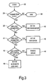
- Fig. 3 is a flow diagram illustrating the operation of the dongle 10, under the control of the MCU 14.
- the MCU polls the first host port H1 in step 34, to determine whether there is any connection thereto. If there is no connection, the process ends at step 36.
- the MCU determines in step 38 whether there is a USB Host connected to the first host port H1. If there is a USB Host connected to the first host port H1, then the process passes to step 40, in which the dongle 10 acts as a USB transceiver. That is, it passes communications directly between the first host port H1 and the second host port H2, allowing the connected USB Host to control communications with any USB device (or devices) connected to the second host port H2 in the conventional way.
- step 38 determines in step 38 that there is a USB Device, rather than a USB Host, connected to the first host port H1
- the process passes to step 41, in which it determines if there is a USB Host connected to the second host port H2. If so, then in step 42 the USB Device core within the USB Host/Device Controller 12 operates to allow conventional USB communications between the USB Device connected to the first host port H1 and the USB Host connected to the second host port H2.
- the MCU 14 enumerates the USB Device connected to the first host port H1 in step 43, and checks if it is a device running VirtualHAL. If the MCU determines in step 43 that the connected device 4 is not running VirtualHAL, it will disable the device 4 in step 44 and, for example, will trigger a flashing LED, signaling that the connected device 4 does not support VirtualHAL.
- the MCU 14 determines in step 42 that the connected device 4 is running VirtualHAL, (i.e. that it has a VirtualHAL driver 16) the MCU 14 will go into operational mode in step 46, allowing the dongle 10 (together with the device 4) to act as an alternate USB Host. In this mode, which will be described in more detail below, the dongle 10 can control communications with any USB device (or devices) connected to the second host port H2.
- a Host Stack accesses underlying USB Hardware through the HostHAL.
- a Device Stack accesses underlying USB hardware though a Device HAL.
- the SoftHost system when the Host Stack (or host station driver software) 20 needs to access the Host Hardware 12, it communicates the access operation details to the VirtualHAL Driver 16.
- the VirtualHAL Driver 16 wraps these access operation details in a pre-determined SoftHost Protocol.
- the SoftHost protocol packet is sent out through the existing USB Device Hardware 22 when the SoftHost Dongle 10 polls it for outstanding SoftHost Protocol packets.
- the VirtualHAL Driver software 16 emulates the presence of a host controller towards the host station driver software. That is, from the point of view of the Host Stack 20, communicating with the VirtualHAL Driver 16 is no different from communicating with a HostHAL in a conventional system. The Host Stack 20 will see an actual Host Hardware through the VirtualHAL Driver 16.
- the VirtualHAL Driver software 16 emulates the presence of a device controller towards the device controller (or device stack) 22.
- the VirtualHAL Driver software 16 thus translates communications between the host station driver software 20 and the device controller.
- the SoftHost Protocol provides the following access functions:
- More advanced functions could be added to improve the system performance, for example, a function that reads a register, AND/ORs it with a value and writes the amended value back into the register.
- the SoftHost Protocol defines the method by which the Host Stack 20 running on VirtualHAL may access the hardware of the Host Controller 12 using the Device Controller hardware.
- the SoftHost protocol is described in detail below.
- the term "HostDongle” is used to refer to the dongle 10
- the term “HostOnDevice” is used to refer to the device 4, namely an embedded system with USB device hardware 22, running a Host Stack 20 on VirtualHAL 16.
- the SoftHost protocol starts at the end of Fig. 3, at the point where the HostDongle 10 has enumerated the connected device 4 and the connected device 4 is confirmed to be a HostOnDevice.
- the MCU 14 sets up an interrupt pipe and polls the VirtualHAL driver 16 for data every millisecond.
- Data sent between the device 4 and dongle 10 is sent by means of the SoftHost protocol, in the form of SoftHost Packets. If the Host Stack 20 on the PDA 4 has sent a hardware access request through the VirtualHAL Driver 16, the VirtualHAL Driver 16 will send the request as a SoftHostPacket when the first host port H1 of the dongle 10 polls it through the interrupt pipe.
- the MCU 14 will retrieve this SoftHost Packet from the buffer memory of the embedded USB Host Controller 12 and execute the hardware access accordingly. If there is any data to be returned (read operations), the MCU 14 will send out the corresponding data through Host 1.
- HRU HostDongle Request Unit
- HRU_IRQ Interrupt Information
- HostOnDevice 4 would reply with NOB or CRP through this bulk-in.
- transfers start with an action by the Host.
- the SoftHost Dongle 10 is always the Host. All SoftHost transfer cycles starts with a HRU, as defined above. The current transfer cycle must be completed before the HostDongle 10 starts the next transfer cycle.
- Active bit in Header is 1 for CRP, and 0 for APR.
- CRP can be of a size of 16-64 bytes.
- the total size is made up of A number of command sets (8 bytes each) An optional data set.
- Maximum size of data set is 64-(8* number of command sets).
- the multiple command sets in a single command request packet allows a sequence of hardware accesses to be communicated in a single packet and thus reduces the latency transfer.
- Command Set is an 8-byte data structure. It contains the following information:
- the Virtual Hardware Abstraction Layer (VirtualHAL) therefore provides complete access to the target hardware on the connected dongle, using the USB Device hardware.
- the existing USB Device hardware is used as an asynchronous microprocessor interface bus to allow the USB Host Driver to access the target hardware.
- VirtualHAL provides the advantages that the hardware dongle does not need to handle USB software, which allows the dongle to be low cost, and the Host software can be handled by the embedded system on the USB Device.
- a hardware dongle that allows a USB Device to attain the capability of USB Host without changes to the existing hardware.
- the USB Device runs emulation software that can be handled by the embedded system on the USB Device. This provides the advantages that the hardware dongle does not need to handle USB software, which allows the dongle to be low cost.
- the invention has been described up to this point with reference to a system in which the VirtualHAL driver software allows the USB Device to function as a USB Host in conjunction with the dongle 10.
- similarly structured VirtualHAL driver software could be used to add in multiple interface/functions to a system with USB Device capability.
- the driver software could allows the USB Device to communicate over Bluetooth, IrDA, USB-OTG, or other communications protocols.
Landscapes
- Engineering & Computer Science (AREA)
- Theoretical Computer Science (AREA)
- Physics & Mathematics (AREA)
- General Engineering & Computer Science (AREA)
- General Physics & Mathematics (AREA)
- Information Transfer Systems (AREA)
- Bus Control (AREA)
- Small-Scale Networks (AREA)
- Communication Control (AREA)
- Mechanical Coupling Of Light Guides (AREA)
- Use Of Switch Circuits For Exchanges And Methods Of Control Of Multiplex Exchanges (AREA)
Abstract
Description
- This invention relates to a bus connection system, and in particular to a device which can be used with electronic equipment in a bus communication system to allow the equipment to act as a host within the system.
- The Universal Serial Bus (USB) communication system is becoming very widespread.
- In a USB system, it is possible to interconnect many items of electronic equipment, such as personal computers, scanners, mobile phones, printers, etc. In any system, one item of equipment is always designated as the USB host, which controls connections with all of the other items, or USB devices. Personal computers are typically provided with the hardware and software required to allow them to act as USB hosts, but other items are typically not provided with the required hardware and software, and thus can only act as USB devices.
- There are however situations in which it would be useful for an item of equipment to be able to act as a USB host, without requiring major modification of the equipment.
- US 5,784,581 discloses an apparatus, which can act as a USB slave device when a USB host is connected to a privileged port, or alternatively can act as a USB host to a slave device connected to a second port, when no USB host is connected to the privileged port.
- According to an aspect of the present invention, there is provided a bus station, preferably in the form of a hardware dongle, which can be connected to the bus communication port of a bus communication device, enabling it to act as a bus host. In the preferred embodiments of the invention, the bus station operates in the USB system, although the invention is also applicable to other bus communication systems.
- More specifically, one aspect of the present invention provides a bus station which, when it determines that a bus host is connected to a first bus communication port thereof, acts as a transceiver to allow conventional bus communications between said bus host and a bus device connected to a second bus communication port thereof; and which, when it determines that a bus device running suitable software is connected to the first bus communication port thereof, acts as an alternate host to allow bus communications between said bus device connected to the first bus communication port and a bus device connected to a second bus communication port.
- The invention is as set out by the
independent claims 1, 4 and 5. - Fig. 1 is a block schematic diagram of a bus communication system.
- Fig. 2 is a block diagram showing the hardware and software in the system of Fig. 1.
- Fig. 3 is a flow chart showing a method in accordance with an aspect of the present invention.
- Fig. 1 is a block schematic diagram of a bus communication system in accordance with the invention.
- The
system 2 comprises afirst USB Device 4 with aUSB port 6, asecond USB Device 8 and adongle 10. - In this illustrated embodiment, the
first USB Device 4 is a personal digital assistant (PDA), but it will be appreciated that the invention is applicable to any USB Device such as a mobile communications device, digital camera or a personal organizer. - The
second USB Device 8 may be any USB Device including a printer, mouse, hard disk or modem. - The
dongle 10 comprises an Embedded USB Host/Device Controller 12 with a first host port H1 and a second host port H2, and a low power Micro Controller Unit (MCU) 14. - The first host port H1 of the
dongle 10 may be connected, as shown in Fig. 1, to theUSB port 6 of thePDA 4. When the first host port H1 of thedongle 10 is connected to theUSB port 6 of thePDA 4, the PDA is effectively enabled to act as a USB Host, and the second host port H2 of thedongle 10 then effectively functions as a Host port of thePDA 4. Thus, thePDA 4 may control communications with any USB Device connected to the second host port H2 of thedongle 10 by means of aUSB bus 15. - It should be noted that, while the first host port H1 and the second host port H2 are shown here connected to the same USB Host/
Device Controller 12, it would be possible for theMCU 14 to communicate with the first host port H1 and the second host port H2 through two independent USB Host/Device Controllers, the first being dedicated to communication with thePDA 4, and the second being dedicated to communication with the connected USB device, or devices, 8. - In order to allow the
PDA 4 to act as a USB Host when connected to thedongle 10, thePDA 4 requires a driver update. - The driver update is specific to the particular USB Device which is in use, and serves to add in a Virtual Hardware Abstraction Layer (VirtualHAL) software driver, which runs on top of the existing USB Device Hardware in the
PDA 4. - Fig. 2 is a block diagram of the hardware and software in the system of Fig. 1.
- As is conventional, the
USB Device 4 has anoperating system 18, aHost Stack 20 and Device Stack and Device Hardware 22. In order to be able to act as a USB Host, thePDA 4 also runs the VirtualHALdriver software 16. When theUSB Device 4 is running the VirtualHALdriver software 16, it is sometimes referred to herein as a HostOnDevice. - The
dongle 10 comprises Host Hardware 12 (that is, the USB host controller), MCU 14 and SoftHost Firmware 24. - The SoftHost protocol layer, which will be described in more detail below, controls the communications between the
device 4 and thedongle 10 over thedongle connector 28. - Fig. 3 is a flow diagram illustrating the operation of the
dongle 10, under the control of theMCU 14. Upon powering up, atstep 32 in Fig. 3, the MCU polls the first host port H1 instep 34, to determine whether there is any connection thereto. If there is no connection, the process ends atstep 36. - If there is a connection, the MCU determines in
step 38 whether there is a USB Host connected to the first host port H1. If there is a USB Host connected to the first host port H1, then the process passes tostep 40, in which thedongle 10 acts as a USB transceiver. That is, it passes communications directly between the first host port H1 and the second host port H2, allowing the connected USB Host to control communications with any USB device (or devices) connected to the second host port H2 in the conventional way. - If the MCU determines in
step 38 that there is a USB Device, rather than a USB Host, connected to the first host port H1, the process passes tostep 41, in which it determines if there is a USB Host connected to the second host port H2. If so, then instep 42 the USB Device core within the USB Host/Device Controller 12 operates to allow conventional USB communications between the USB Device connected to the first host port H1 and the USB Host connected to the second host port H2. - If there is a USB Device connected to the second host port H2, the
MCU 14 enumerates the USB Device connected to the first host port H1 instep 43, and checks if it is a device running VirtualHAL. If the MCU determines instep 43 that the connecteddevice 4 is not running VirtualHAL, it will disable thedevice 4 instep 44 and, for example, will trigger a flashing LED, signaling that the connecteddevice 4 does not support VirtualHAL. - If the MCU determines in
step 42 that the connecteddevice 4 is running VirtualHAL, (i.e. that it has a VirtualHAL driver 16) theMCU 14 will go into operational mode instep 46, allowing the dongle 10 (together with the device 4) to act as an alternate USB Host. In this mode, which will be described in more detail below, thedongle 10 can control communications with any USB device (or devices) connected to the second host port H2. - In a conventional system, where a personal computer is a USB Host, a Host Stack accesses underlying USB Hardware through the HostHAL. Similarly, in a conventional PDA USB Device, a Device Stack accesses underlying USB hardware though a Device HAL.
- However, in accordance with the invention, in the SoftHost system, when the Host Stack (or host station driver software) 20 needs to access the Host Hardware 12, it communicates the access operation details to the VirtualHAL
Driver 16. The VirtualHALDriver 16 wraps these access operation details in a pre-determined SoftHost Protocol. The SoftHost protocol packet is sent out through the existingUSB Device Hardware 22 when the SoftHost Dongle 10 polls it for outstanding SoftHost Protocol packets. - Thus, the VirtualHAL
Driver software 16 emulates the presence of a host controller towards the host station driver software. That is, from the point of view of the Host Stack 20, communicating with the VirtualHALDriver 16 is no different from communicating with a HostHAL in a conventional system. The Host Stack 20 will see an actual Host Hardware through the VirtualHALDriver 16. - Conversely, the VirtualHAL
Driver software 16 emulates the presence of a device controller towards the device controller (or device stack) 22. The VirtualHALDriver software 16 thus translates communications between the hoststation driver software 20 and the device controller. - The SoftHost Protocol provides the following access functions:
- Reading a register in the
dongle Host Hardware 12 - Writing a register in the
dongle Host Hardware 12 - Reading buffer memory in the
dongle Host Hardware 12 - Writing buffer memory in the
dongle Host Hardware 12 - More advanced functions could be added to improve the system performance, for example, a function that reads a register, AND/ORs it with a value and writes the amended value back into the register.
- The SoftHost Protocol defines the method by which the Host Stack 20 running on VirtualHAL may access the hardware of the
Host Controller 12 using the Device Controller hardware. The SoftHost protocol is described in detail below. In this description, the term "HostDongle" is used to refer to thedongle 10, while the term "HostOnDevice" is used to refer to thedevice 4, namely an embedded system withUSB device hardware 22, running aHost Stack 20 on VirtualHAL 16. - The SoftHost protocol starts at the end of Fig. 3, at the point where the HostDongle 10 has enumerated the connected
device 4 and the connecteddevice 4 is confirmed to be a HostOnDevice. - In operational mode, the
MCU 14 sets up an interrupt pipe and polls the VirtualHALdriver 16 for data every millisecond. Data sent between thedevice 4 anddongle 10 is sent by means of the SoftHost protocol, in the form of SoftHost Packets. If theHost Stack 20 on thePDA 4 has sent a hardware access request through theVirtualHAL Driver 16, theVirtualHAL Driver 16 will send the request as a SoftHostPacket when the first host port H1 of thedongle 10 polls it through the interrupt pipe. - The
MCU 14 will retrieve this SoftHost Packet from the buffer memory of the embeddedUSB Host Controller 12 and execute the hardware access accordingly. If there is any data to be returned (read operations), theMCU 14 will send out the corresponding data through Host 1. - The
HostDongle 10 and theHostOnDevice 4 communicate using a dedicated bi-directional bulk pipe. There are four types of payloads.HRU (HostDongle Request Unit) Sent by HostDongle 10 A bulk packet of 8 bytes payload Used for polling the HostOnDevice 4May contain Interrupt Information (HRU_IRQ) HostDongle 10 ALWAYS sends a bulk-in of 64 bytes after sending the HRU.HostOnDevice 4 would reply with NOB or CRP through this bulk-in.NOB (No Outstanding Business) Sent by HostOnDevice 4 A bulk packet of 8 bytes payload Sent when there are no outstanding transactions CRP (Common Request Packet) Sent by HostOnDevice 4 A bulk packet of 16-64 bytes Contains the results of previously received CRP commands, and an optimal data set. APR (As Per Requested) Sent by HostDongle 10 A bulk packet of 16-64 bytes - As in all USB systems, transfers start with an action by the Host. In the case of the SoftHost protocol, the
SoftHost Dongle 10 is always the Host. All SoftHost transfer cycles starts with a HRU, as defined above. The current transfer cycle must be completed before the HostDongle 10 starts the next transfer cycle. - Poll-Nothing Cycle: HRU-NOB
HostDongle 10 polls theHostOnDevice 4 for outstanding command sets. If there are no outstanding command sets,HostOnDevice 4 replies with NOB.
Transactions:-
HostDongle 10 sends BULK-OUT -
HostDongle 10 sends DATA (HRU) -
HostOnDevice 4 sends ACK
-
HostDongle 10 sends BULK-IN -
HostOnDevice 4 sends DATA (NOB) -
HostDongle 10 sends ACK
-
- Poll-Something Cycle: HRU-CRP-APR
HostDongle 10 polls theHostOnDevice 4 for outstanding command sets.
HostOnDevice 4 sends outstanding command set by CRP.HostDongle 10 executes the command and returns the results by APR.
Transactions:-
HostDongle 10 sends BULK-OUT -
HostDongle 10 sends DATA (HRU) -
HostOnDevice 4 sends ACK
-
HostDongle 10 sends BULK-IN -
HostOnDevice 4 sends DATA (CRP) -
HostDongle 10 sends ACK
-
HostDongle 10 sends BULK-OUT -
HostDongle 10 sends DATA (APR) -
HostOnDevice 4 sends ACK
-
- Interrupt Cycle: HRU_JRQ-CRP-APR
HostDongle 10 alerts theHostOnDevice 4 on outstanding hardware interrupts.
HostOnDevice 4 decides on the appropriate command sets and sends them by CRP.
HostDongle 10 executes the commands and returns the results by APR.
HostOnDevice 4 MUST clear the outstanding interrupt or disable the generation of HRU_IRQ, or theHostDongle 10 would send HRU_IRQ continuously.
Transactions:-
HostDongle 10 sends BULK-OUT -
HostDongle 10 sends DATA (HRU_IRQ) -
HostOnDevice 4 sends ACK
-
HostDongle 10 sends BULK-IN -
HostOnDevice 4 sends DATA (CRP) -
HostDongle 10 sends ACK
-
HostDongle 10 sends BULK-OUT -
HostDongle 10 sends DATA (APR) -
HostOnDevice 4 sends ACK
-
-
- The HRU contains the following information:
- Current Frame Number
- HclnterruptStatus of
Host Controller 12 inHostDongle 10
Interrupt Status ofDevice Controller 22 - No special information required
- Active bit in Header is 1 for CRP, and 0 for APR.
- CRP can be of a size of 16-64 bytes. The total size is made up of
A number of command sets (8 bytes each)
An optional data set. - Maximum number of command sets in a CRP is 8.
- Maximum size of data set is 64-(8* number of command sets).
- The multiple command sets in a single command request packet allows a sequence of hardware accesses to be communicated in a single packet and thus reduces the latency transfer.
- Command Set is an 8-byte data structure. It contains the following information:
- Command Set Header (1 byte)
- Command Set Index (2 bytes)
- Command Set Data (4 bytes)
- Command Set Aux (1 byte)
- The Virtual Hardware Abstraction Layer (VirtualHAL) therefore provides complete access to the target hardware on the connected dongle, using the USB Device hardware. In other words, the existing USB Device hardware is used as an asynchronous microprocessor interface bus to allow the USB Host Driver to access the target hardware.
- The use of VirtualHAL provides the advantages that the hardware dongle does not need to handle USB software, which allows the dongle to be low cost, and the Host software can be handled by the embedded system on the USB Device.
- Therefore, in the preferred embodiments of the invention, there is provided a hardware dongle that allows a USB Device to attain the capability of USB Host without changes to the existing hardware. In order to achieve this, the USB Device runs emulation software that can be handled by the embedded system on the USB Device. This provides the advantages that the hardware dongle does not need to handle USB software, which allows the dongle to be low cost.
- The invention has been described up to this point with reference to a system in which the VirtualHAL driver software allows the USB Device to function as a USB Host in conjunction with the
dongle 10. However, similarly structured VirtualHAL driver software could be used to add in multiple interface/functions to a system with USB Device capability. For example, the driver software could allows the USB Device to communicate over Bluetooth, IrDA, USB-OTG, or other communications protocols.
| Bit | 7 | 6 | 5 | 4 | 3 | 2 | 1 | 0 |
| Group | Active | Remaining Sets | OpCode | |||||
| Attribute | Boolean | 0-7.0 means last set | 0-15 | |||||
| OpCode | Operation by MCU |
| 0 | Write [Aux] bytes from [Data] into [Index] register |
| 1 | Read [Aux] bytes from [Index] register into [Data] |
| 2 | Write [Data] bytes from DataSet into address location [Index] |
| 3 | Read [Data] bytes into DataSet from address location [Index] |
| 4 | Read [Aux] bytes from [Index] register, OR with [Data] and write back into [Index] register |
| 5 | Read [Aux] bytes from [Index] register, AND with [Data] and write back into [Index] |
| 6 | Set polling rate to [Index] |
| 7 | Set HRU_IRQ On/Off |
| 8-15 | Reserved. No Action by MCU |
Claims (5)
- A bus station (10) for use in a bus communication system, a first communication port (H2) and a second communication port (H1), being arranged to operate in a first mode upon detection of the presence of a host station coupled to said second port and to operate in a second mode upon detection of the absence of a host station coupled to said second port, characterized in that said bus station (10) is arranged in said first mode of operation to pass communication between said host station coupled to said second port (H1) and a device station (8) coupled to said first port (H2), and in that said bus station (10) is further arranged to operate as an alternate host station in said second mode of operation, by communicating with said device station (8) coupled to said first port (H2) according to a communication protocol whereby said bus station (10) initiates communications.
- A bus station according to claim 1 wherein said bus station is arranged to operate as a USB transceiver in said first mode of operation and to operate as a USB host in said second mode of operation.
- A bus station according to claim 1 wherein said bus station further comprises transceiver circuitry coupled to said first and second port for passing communication between said host station coupled to said second port and said device station in said first mode of operation.
- A bus station (4) for use in a bus system, comprising a device controller (22) coupled to a communication port, being arranged to operate as a device station, said bus station further being arranged to operate under control of system software, comprising an operating system (18) and characterized in that the system comprises host station driver software (20) being arranged to communicate with a host controller and to pass information to and from the operating system, wherein said system software further comprises host emulation software (16) being arranged to emulate the presence of a host controller towards the host station driver software (20) and the presence of device station driver software towards the device controller (22), further being arranged to translate communications from the host station driver software (20) to the device controller (22) and vice versa.
- A bus communication system comprising a first bus station (4) including a device communication port (6) and a second bus station (10), said second bus station further comprising a second communication port (H1), said second bus station (10) being arranged to operate in a first mode upon detection of the presence of a host station coupled to said second port (H1) and to operate in a second mode upon detection of the absence of a host station coupled to said second port,
characterized in that said first bus station (4) comprises a device controller (22) coupled to said device communication port and is arranged to operate under control of system software, comprising an operating system (18) and host station driver software (20) being arranged to communicate with a host controller and to pass information to and from the operating system, wherein said system software further comprises host emulation software (16) being arranged to emulate the presence of a host controller towards the host station driver software (20) and the presence of device station driver software towards the device controller (22), further being arranged to translate communications from the host station driver software (20) to the device controller (22) and vice versa.
Applications Claiming Priority (3)
| Application Number | Priority Date | Filing Date | Title |
|---|---|---|---|
| WOPCT/SG02/00239 | 2002-09-24 | ||
| SG0200239 | 2002-09-24 | ||
| PCT/IB2003/002236 WO2004029817A1 (en) | 2002-09-24 | 2003-05-22 | Bus connection system |
Publications (2)
| Publication Number | Publication Date |
|---|---|
| EP1546897A1 EP1546897A1 (en) | 2005-06-29 |
| EP1546897B1 true EP1546897B1 (en) | 2006-12-20 |
Family
ID=32041145
Family Applications (1)
| Application Number | Title | Priority Date | Filing Date |
|---|---|---|---|
| EP03725545A Expired - Lifetime EP1546897B1 (en) | 2002-09-24 | 2003-05-22 | Bus connection system |
Country Status (9)
| Country | Link |
|---|---|
| US (1) | US7640385B2 (en) |
| EP (1) | EP1546897B1 (en) |
| JP (2) | JP2006500672A (en) |
| CN (1) | CN1685326B (en) |
| AT (1) | ATE349044T1 (en) |
| AU (1) | AU2003228076A1 (en) |
| DE (1) | DE60310586T2 (en) |
| TW (1) | TWI320142B (en) |
| WO (1) | WO2004029817A1 (en) |
Families Citing this family (47)
| Publication number | Priority date | Publication date | Assignee | Title |
|---|---|---|---|---|
| JP3962696B2 (en) * | 2003-02-21 | 2007-08-22 | キヤノン株式会社 | Information processing apparatus, control method thereof, and control program |
| US7174405B1 (en) * | 2003-06-06 | 2007-02-06 | Cisco Technology, Inc. | Method and system for replacing a read-modify-write operation with an atomic set-bits or clear-bits operation |
| TWI241520B (en) * | 2003-07-08 | 2005-10-11 | Ours Technology Inc | Universal serial bus device for exchange data each other |
| TWI226551B (en) * | 2003-10-28 | 2005-01-11 | Prolific Technology Inc | Multi-function wireless bridge for USB and associated system |
| CN1906559B (en) * | 2003-12-30 | 2010-10-13 | 威步系统股份公司 | Method for controlling data processing device |
| CN100375495C (en) * | 2004-04-26 | 2008-03-12 | 全友电脑股份有限公司 | Scanner capable of operating independently |
| EP1754160B1 (en) * | 2004-05-28 | 2010-05-05 | Nxp B.V. | Bus connection device |
| CN100416531C (en) * | 2004-08-30 | 2008-09-03 | 旺玖科技股份有限公司 | Multifunctional universal serial bus wireless bridging device and system device |
| DE102004042172A1 (en) | 2004-08-31 | 2006-03-09 | Advanced Micro Devices, Inc., Sunnyvale | Segmented on-chip memory and arbitration requesting devices |
| WO2006031681A2 (en) * | 2004-09-10 | 2006-03-23 | Logitech Europe S.A. | Communication of audio control signals for wireless audio headphones |
| CN100388256C (en) * | 2004-09-17 | 2008-05-14 | 宇瞻科技股份有限公司 | USB access device |
| CN1329808C (en) * | 2004-10-09 | 2007-08-01 | 宇瞻科技股份有限公司 | Data coding and decoding device |
| DE102004057756B4 (en) * | 2004-11-30 | 2009-08-06 | Advanced Micro Devices Inc., Sunnyvale | USB control device with OTG control unit |
| US7606951B2 (en) | 2004-11-12 | 2009-10-20 | Woodbridge Nancy G | Memory reuse for multiple endpoints in USB device |
| US20060106962A1 (en) * | 2004-11-17 | 2006-05-18 | Woodbridge Nancy G | USB On-The-Go implementation |
| DE102005009021A1 (en) | 2005-02-28 | 2006-09-07 | Advanced Micro Devices Inc., Sunnyvale | Unified USB OTG control unit |
| US20060206631A1 (en) * | 2005-03-09 | 2006-09-14 | Chin-Chen Kuo | Data duplication method and system used between USB devices |
| CN100401280C (en) * | 2005-06-08 | 2008-07-09 | 北京飞天诚信科技有限公司 | Universal Serial Bus Data Transmission Method |
| US8024500B2 (en) | 2005-08-15 | 2011-09-20 | Research In Motion Limited | Universal peripheral connector |
| DE602005006808D1 (en) * | 2005-08-15 | 2008-06-26 | Research In Motion Ltd | Universal peripheral connector |
| FR2895187B1 (en) * | 2005-12-21 | 2010-12-17 | Eastman Kodak Co | MOBILE HOME EQUIPMENT HOSTING STATION AND RESOURCE SHARING METHOD USING THE STATION |
| US8035368B2 (en) * | 2006-02-13 | 2011-10-11 | Freescale Semiconductor, Inc. | Integrated circuit, universal serial bus on-the-go power source and methods for use therewith |
| US20100225953A1 (en) * | 2006-03-20 | 2010-09-09 | Ernst Engst | Method and assembly for releasing and configuring specific system operations of a printer or photocopier |
| CN101136000B (en) * | 2006-09-01 | 2011-01-05 | 飞思卡尔半导体公司 | Application processor circuit and electronic device for realizing SD host/slave device |
| JP2008107997A (en) * | 2006-10-24 | 2008-05-08 | Seiko Epson Corp | Data communication method, data communication apparatus, and data communication system |
| US7558899B2 (en) * | 2007-04-04 | 2009-07-07 | Imation Corp. | Dongle configured to electrically couple a data storage device and a host computing device |
| US8315269B1 (en) | 2007-04-18 | 2012-11-20 | Cypress Semiconductor Corporation | Device, method, and protocol for data transfer between host device and device having storage interface |
| GB2489344B (en) * | 2007-06-15 | 2012-12-05 | Apple Inc | circuitry and method for regulating a power supply signal |
| TWI448902B (en) | 2007-08-24 | 2014-08-11 | Cypress Semiconductor Corp | Bridge device with page access base processor interface |
| US8090894B1 (en) * | 2007-09-21 | 2012-01-03 | Cypress Semiconductor Corporation | Architectures for supporting communication and access between multiple host devices and one or more common functions |
| US20090276549A1 (en) * | 2008-05-01 | 2009-11-05 | Nokia Corporation | Access for host stacks |
| US8170844B2 (en) * | 2008-05-02 | 2012-05-01 | Northrop Grumman Guidance And Electronics Company, Inc. | Estimation of probability of lambda failure through employment of lookup table |
| US8082381B2 (en) * | 2008-09-02 | 2011-12-20 | Nvidia Corporation | Connecting a plurality of peripherals |
| US20100115116A1 (en) * | 2008-11-03 | 2010-05-06 | Micron Technology, Inc. | System and method for switching communication protocols in electronic interface devices |
| US8103803B2 (en) * | 2008-11-21 | 2012-01-24 | Nvidia Corporation | Communication between a processor and a controller |
| US8610732B2 (en) * | 2008-12-11 | 2013-12-17 | Nvidia Corporation | System and method for video memory usage for general system application |
| US8677074B2 (en) * | 2008-12-15 | 2014-03-18 | Nvidia Corporation | Shared memory access techniques |
| US7970976B2 (en) * | 2009-03-01 | 2011-06-28 | Qualcomm Incorporated | Remote memory access using reversible host/client interface |
| TWI385533B (en) * | 2009-05-11 | 2013-02-11 | Via Tech Inc | Computer system, data-exchange device and data exchange method |
| US8737064B2 (en) * | 2010-01-12 | 2014-05-27 | Microsoft Corporation | Electronic device stand |
| US8373658B2 (en) * | 2010-05-24 | 2013-02-12 | Cywee Group Limited | Motion sensing system |
| US20120259939A1 (en) * | 2011-04-05 | 2012-10-11 | Timothy James Wessman | Calculator |
| CN102820980B (en) * | 2011-06-08 | 2018-11-06 | 南京中兴新软件有限责任公司 | A kind of device and method of transmitting order to lower levels |
| JP5907550B2 (en) * | 2011-08-31 | 2016-04-26 | Necプラットフォームズ株式会社 | USB device and method for controlling USB device |
| JP5734825B2 (en) | 2011-09-09 | 2015-06-17 | 富士通コンポーネント株式会社 | COMMUNICATION DEVICE AND COMMUNICATION DEVICE CONTROL METHOD |
| CN103729324A (en) * | 2014-01-22 | 2014-04-16 | 浪潮电子信息产业股份有限公司 | Security protection device of cloud storage file based on USB3.0 interface |
| US20180113829A1 (en) * | 2015-06-01 | 2018-04-26 | Sony Corporation | Electronic apparatus and coupling method |
Family Cites Families (14)
| Publication number | Priority date | Publication date | Assignee | Title |
|---|---|---|---|---|
| US5784581A (en) * | 1996-05-03 | 1998-07-21 | Intel Corporation | Apparatus and method for operating a peripheral device as either a master device or a slave device |
| US6131125A (en) * | 1997-11-14 | 2000-10-10 | Kawasaki Lsi U.S.A., Inc. | Plug-and-play data cable with protocol translation |
| US6370603B1 (en) * | 1997-12-31 | 2002-04-09 | Kawasaki Microelectronics, Inc. | Configurable universal serial bus (USB) controller implemented on a single integrated circuit (IC) chip with media access control (MAC) |
| TW455805B (en) | 1998-02-26 | 2001-09-21 | Winbond Electronics Corp | Converter allowing data communications equipment to transmit data to data terminal equipment through universal serial bus and the control method thereof |
| JP2000196986A (en) * | 1998-12-25 | 2000-07-14 | Olympus Optical Co Ltd | Electronic image pickup device |
| JP2000196648A (en) * | 1998-12-28 | 2000-07-14 | Toshiba Corp | Electronic device control method and electronic device control device |
| JP2000209238A (en) * | 1999-01-14 | 2000-07-28 | Toshiba Corp | Electronic device control method and electronic device control device |
| GB2350212B (en) * | 1999-02-09 | 2003-10-08 | Adder Tech Ltd | Data routing device and system |
| JP2000316006A (en) | 1999-04-28 | 2000-11-14 | Nec Corp | Node having provision for bus manager function automatic changeover, mobile terminal and mobile terminal system |
| JP2002055936A (en) * | 2000-08-08 | 2002-02-20 | Toshiba Corp | USB device, communication system and communication method between USB device |
| JP2002116853A (en) * | 2000-10-05 | 2002-04-19 | Tdk Corp | Usb mounted electronic equipment and use cable to be used therefor |
| US7000057B1 (en) * | 2002-02-11 | 2006-02-14 | Cypress Semiconductor Corp. | Method and apparatus for adding OTG dual role device capability to a USB peripheral |
| US6732218B2 (en) * | 2002-07-26 | 2004-05-04 | Motorola, Inc. | Dual-role compatible USB hub device and method |
| US7152190B2 (en) * | 2004-02-03 | 2006-12-19 | Motorola Inc. | USB OTG intelligent hub/router for debugging USB OTG devices |
-
2003
- 2003-05-22 WO PCT/IB2003/002236 patent/WO2004029817A1/en not_active Ceased
- 2003-05-22 AT AT03725545T patent/ATE349044T1/en not_active IP Right Cessation
- 2003-05-22 EP EP03725545A patent/EP1546897B1/en not_active Expired - Lifetime
- 2003-05-22 DE DE60310586T patent/DE60310586T2/en not_active Expired - Lifetime
- 2003-05-22 US US10/528,614 patent/US7640385B2/en not_active Expired - Fee Related
- 2003-05-22 AU AU2003228076A patent/AU2003228076A1/en not_active Abandoned
- 2003-05-22 CN CN038226685A patent/CN1685326B/en not_active Expired - Fee Related
- 2003-05-22 JP JP2004539268A patent/JP2006500672A/en active Pending
- 2003-05-28 TW TW092114417A patent/TWI320142B/en not_active IP Right Cessation
-
2009
- 2009-10-05 JP JP2009231540A patent/JP2010061670A/en active Pending
Also Published As
| Publication number | Publication date |
|---|---|
| DE60310586T2 (en) | 2007-10-11 |
| JP2010061670A (en) | 2010-03-18 |
| US7640385B2 (en) | 2009-12-29 |
| US20060059289A1 (en) | 2006-03-16 |
| TW200405172A (en) | 2004-04-01 |
| WO2004029817A1 (en) | 2004-04-08 |
| DE60310586D1 (en) | 2007-02-01 |
| CN1685326A (en) | 2005-10-19 |
| EP1546897A1 (en) | 2005-06-29 |
| JP2006500672A (en) | 2006-01-05 |
| CN1685326B (en) | 2010-05-05 |
| TWI320142B (en) | 2010-02-01 |
| AU2003228076A1 (en) | 2004-04-19 |
| ATE349044T1 (en) | 2007-01-15 |
Similar Documents
| Publication | Publication Date | Title |
|---|---|---|
| US7640385B2 (en) | Dual-mode bus station and system for communications | |
| US7058748B1 (en) | ATA device control via a packet-based interface | |
| US7587528B2 (en) | Control of information units in fibre channel communications | |
| KR101497001B1 (en) | Graphics multi-media ic and method of its operation | |
| US6115771A (en) | Method and system for converting computer peripheral equipment to SCSI-compliant devices | |
| CN101641683B (en) | Enhanced wireless USB protocol and hub | |
| EP2047370B1 (en) | Method and apparatus for distributing usb hub functions across a network | |
| EP2316075B1 (en) | Method and apparatus for connecting usb devices to a remote computer | |
| US7162566B2 (en) | USB-based host-to-host networking method | |
| KR20150036539A (en) | Transmission of multiple protocol data elements via an interface utilizing a data tunnel | |
| US20080065794A1 (en) | Chained DMA for Low-Power Extended USB Flash Device Without Polling | |
| US7802034B2 (en) | Method for performing full transfer automation in a USB controller | |
| CN100476775C (en) | Host controller for bus communication device and bus communication device | |
| EP1899830B1 (en) | Automated serial protocol target port transport layer retry mechanism | |
| CN102843435A (en) | Access and response method and access and response system of storing medium in cluster system | |
| KR20040041623A (en) | Bus system and bus interface for connection to a bus | |
| US20040103163A1 (en) | Serial bus disk extender and portable storage device | |
| EP0815678A2 (en) | Link protocol for transferring data between processors | |
| KR20040043198A (en) | Bus system and bus interface | |
| WO2008082530A1 (en) | Method and apparatus for performing full transfer automation in a usb controller | |
| EP2300925B1 (en) | System to connect a serial scsi array controller to a storage area network | |
| KR101005397B1 (en) | Bus station and bus communication system | |
| US20050273541A1 (en) | Circuit and method for adaptively recognizing a data packet in a universal serial bus network device | |
| US20070022226A1 (en) | Direct memory access system for iSCSI | |
| JP2003523576A (en) | Link bridge |
Legal Events
| Date | Code | Title | Description |
|---|---|---|---|
| PUAI | Public reference made under article 153(3) epc to a published international application that has entered the european phase |
Free format text: ORIGINAL CODE: 0009012 |
|
| 17P | Request for examination filed |
Effective date: 20050425 |
|
| AK | Designated contracting states |
Kind code of ref document: A1 Designated state(s): AT BE BG CH CY CZ DE DK EE ES FI FR GB GR HU IE IT LI LU MC NL PT RO SE SI SK TR |
|
| AX | Request for extension of the european patent |
Extension state: AL LT LV MK |
|
| DAX | Request for extension of the european patent (deleted) | ||
| GRAP | Despatch of communication of intention to grant a patent |
Free format text: ORIGINAL CODE: EPIDOSNIGR1 |
|
| GRAS | Grant fee paid |
Free format text: ORIGINAL CODE: EPIDOSNIGR3 |
|
| GRAA | (expected) grant |
Free format text: ORIGINAL CODE: 0009210 |
|
| AK | Designated contracting states |
Kind code of ref document: B1 Designated state(s): AT BE BG CH CY CZ DE DK EE ES FI FR GB GR HU IE IT LI LU MC NL PT RO SE SI SK TR |
|
| PG25 | Lapsed in a contracting state [announced via postgrant information from national office to epo] |
Ref country code: IT Free format text: LAPSE BECAUSE OF FAILURE TO SUBMIT A TRANSLATION OF THE DESCRIPTION OR TO PAY THE FEE WITHIN THE PRESCRIBED TIME-LIMIT;WARNING: LAPSES OF ITALIAN PATENTS WITH EFFECTIVE DATE BEFORE 2007 MAY HAVE OCCURRED AT ANY TIME BEFORE 2007. THE CORRECT EFFECTIVE DATE MAY BE DIFFERENT FROM THE ONE RECORDED. Effective date: 20061220 Ref country code: RO Free format text: LAPSE BECAUSE OF FAILURE TO SUBMIT A TRANSLATION OF THE DESCRIPTION OR TO PAY THE FEE WITHIN THE PRESCRIBED TIME-LIMIT Effective date: 20061220 Ref country code: AT Free format text: LAPSE BECAUSE OF FAILURE TO SUBMIT A TRANSLATION OF THE DESCRIPTION OR TO PAY THE FEE WITHIN THE PRESCRIBED TIME-LIMIT Effective date: 20061220 Ref country code: SI Free format text: LAPSE BECAUSE OF FAILURE TO SUBMIT A TRANSLATION OF THE DESCRIPTION OR TO PAY THE FEE WITHIN THE PRESCRIBED TIME-LIMIT Effective date: 20061220 Ref country code: DK Free format text: LAPSE BECAUSE OF FAILURE TO SUBMIT A TRANSLATION OF THE DESCRIPTION OR TO PAY THE FEE WITHIN THE PRESCRIBED TIME-LIMIT Effective date: 20061220 Ref country code: CZ Free format text: LAPSE BECAUSE OF FAILURE TO SUBMIT A TRANSLATION OF THE DESCRIPTION OR TO PAY THE FEE WITHIN THE PRESCRIBED TIME-LIMIT Effective date: 20061220 Ref country code: BE Free format text: LAPSE BECAUSE OF FAILURE TO SUBMIT A TRANSLATION OF THE DESCRIPTION OR TO PAY THE FEE WITHIN THE PRESCRIBED TIME-LIMIT Effective date: 20061220 Ref country code: FI Free format text: LAPSE BECAUSE OF FAILURE TO SUBMIT A TRANSLATION OF THE DESCRIPTION OR TO PAY THE FEE WITHIN THE PRESCRIBED TIME-LIMIT Effective date: 20061220 Ref country code: SK Free format text: LAPSE BECAUSE OF FAILURE TO SUBMIT A TRANSLATION OF THE DESCRIPTION OR TO PAY THE FEE WITHIN THE PRESCRIBED TIME-LIMIT Effective date: 20061220 Ref country code: CH Free format text: LAPSE BECAUSE OF FAILURE TO SUBMIT A TRANSLATION OF THE DESCRIPTION OR TO PAY THE FEE WITHIN THE PRESCRIBED TIME-LIMIT Effective date: 20061220 Ref country code: LI Free format text: LAPSE BECAUSE OF FAILURE TO SUBMIT A TRANSLATION OF THE DESCRIPTION OR TO PAY THE FEE WITHIN THE PRESCRIBED TIME-LIMIT Effective date: 20061220 Ref country code: NL Free format text: LAPSE BECAUSE OF FAILURE TO SUBMIT A TRANSLATION OF THE DESCRIPTION OR TO PAY THE FEE WITHIN THE PRESCRIBED TIME-LIMIT Effective date: 20061220 |
|
| REG | Reference to a national code |
Ref country code: GB Ref legal event code: FG4D |
|
| REG | Reference to a national code |
Ref country code: CH Ref legal event code: EP |
|
| REF | Corresponds to: |
Ref document number: 60310586 Country of ref document: DE Date of ref document: 20070201 Kind code of ref document: P |
|
| REG | Reference to a national code |
Ref country code: IE Ref legal event code: FG4D |
|
| PG25 | Lapsed in a contracting state [announced via postgrant information from national office to epo] |
Ref country code: BG Free format text: LAPSE BECAUSE OF FAILURE TO SUBMIT A TRANSLATION OF THE DESCRIPTION OR TO PAY THE FEE WITHIN THE PRESCRIBED TIME-LIMIT Effective date: 20070320 Ref country code: SE Free format text: LAPSE BECAUSE OF FAILURE TO SUBMIT A TRANSLATION OF THE DESCRIPTION OR TO PAY THE FEE WITHIN THE PRESCRIBED TIME-LIMIT Effective date: 20070320 |
|
| PG25 | Lapsed in a contracting state [announced via postgrant information from national office to epo] |
Ref country code: ES Free format text: LAPSE BECAUSE OF FAILURE TO SUBMIT A TRANSLATION OF THE DESCRIPTION OR TO PAY THE FEE WITHIN THE PRESCRIBED TIME-LIMIT Effective date: 20070331 |
|
| PG25 | Lapsed in a contracting state [announced via postgrant information from national office to epo] |
Ref country code: PT Free format text: LAPSE BECAUSE OF FAILURE TO SUBMIT A TRANSLATION OF THE DESCRIPTION OR TO PAY THE FEE WITHIN THE PRESCRIBED TIME-LIMIT Effective date: 20070424 |
|
| NLV1 | Nl: lapsed or annulled due to failure to fulfill the requirements of art. 29p and 29m of the patents act | ||
| REG | Reference to a national code |
Ref country code: CH Ref legal event code: PL |
|
| ET | Fr: translation filed | ||
| PLBE | No opposition filed within time limit |
Free format text: ORIGINAL CODE: 0009261 |
|
| STAA | Information on the status of an ep patent application or granted ep patent |
Free format text: STATUS: NO OPPOSITION FILED WITHIN TIME LIMIT |
|
| 26N | No opposition filed |
Effective date: 20070921 |
|
| PG25 | Lapsed in a contracting state [announced via postgrant information from national office to epo] |
Ref country code: MC Free format text: LAPSE BECAUSE OF NON-PAYMENT OF DUE FEES Effective date: 20070531 |
|
| PG25 | Lapsed in a contracting state [announced via postgrant information from national office to epo] |
Ref country code: GR Free format text: LAPSE BECAUSE OF FAILURE TO SUBMIT A TRANSLATION OF THE DESCRIPTION OR TO PAY THE FEE WITHIN THE PRESCRIBED TIME-LIMIT Effective date: 20070321 |
|
| PG25 | Lapsed in a contracting state [announced via postgrant information from national office to epo] |
Ref country code: IE Free format text: LAPSE BECAUSE OF NON-PAYMENT OF DUE FEES Effective date: 20070522 |
|
| REG | Reference to a national code |
Ref country code: GB Ref legal event code: 732E |
|
| PG25 | Lapsed in a contracting state [announced via postgrant information from national office to epo] |
Ref country code: EE Free format text: LAPSE BECAUSE OF FAILURE TO SUBMIT A TRANSLATION OF THE DESCRIPTION OR TO PAY THE FEE WITHIN THE PRESCRIBED TIME-LIMIT Effective date: 20061220 |
|
| REG | Reference to a national code |
Ref country code: FR Ref legal event code: TP |
|
| PG25 | Lapsed in a contracting state [announced via postgrant information from national office to epo] |
Ref country code: LU Free format text: LAPSE BECAUSE OF NON-PAYMENT OF DUE FEES Effective date: 20070522 Ref country code: CY Free format text: LAPSE BECAUSE OF FAILURE TO SUBMIT A TRANSLATION OF THE DESCRIPTION OR TO PAY THE FEE WITHIN THE PRESCRIBED TIME-LIMIT Effective date: 20061220 |
|
| PG25 | Lapsed in a contracting state [announced via postgrant information from national office to epo] |
Ref country code: HU Free format text: LAPSE BECAUSE OF FAILURE TO SUBMIT A TRANSLATION OF THE DESCRIPTION OR TO PAY THE FEE WITHIN THE PRESCRIBED TIME-LIMIT Effective date: 20070621 Ref country code: TR Free format text: LAPSE BECAUSE OF FAILURE TO SUBMIT A TRANSLATION OF THE DESCRIPTION OR TO PAY THE FEE WITHIN THE PRESCRIBED TIME-LIMIT Effective date: 20061220 |
|
| REG | Reference to a national code |
Ref country code: FR Ref legal event code: PLFP Year of fee payment: 13 |
|
| REG | Reference to a national code |
Ref country code: FR Ref legal event code: PLFP Year of fee payment: 14 |
|
| REG | Reference to a national code |
Ref country code: DE Ref legal event code: R082 Ref document number: 60310586 Country of ref document: DE Representative=s name: GRUENECKER PATENT- UND RECHTSANWAELTE PARTG MB, DE Ref country code: DE Ref legal event code: R081 Ref document number: 60310586 Country of ref document: DE Owner name: OCT CIRCUIT TECHNOLOGIES INTERNATIONAL LTD., IE Free format text: FORMER OWNER: NXP B.V., EINDHOVEN, NL |
|
| REG | Reference to a national code |
Ref country code: FR Ref legal event code: PLFP Year of fee payment: 15 |
|
| PGFP | Annual fee paid to national office [announced via postgrant information from national office to epo] |
Ref country code: DE Payment date: 20170420 Year of fee payment: 15 Ref country code: FR Payment date: 20170421 Year of fee payment: 15 Ref country code: GB Payment date: 20170426 Year of fee payment: 15 |
|
| REG | Reference to a national code |
Ref country code: DE Ref legal event code: R119 Ref document number: 60310586 Country of ref document: DE |
|
| GBPC | Gb: european patent ceased through non-payment of renewal fee |
Effective date: 20180522 |
|
| PG25 | Lapsed in a contracting state [announced via postgrant information from national office to epo] |
Ref country code: FR Free format text: LAPSE BECAUSE OF NON-PAYMENT OF DUE FEES Effective date: 20180531 Ref country code: DE Free format text: LAPSE BECAUSE OF NON-PAYMENT OF DUE FEES Effective date: 20181201 Ref country code: GB Free format text: LAPSE BECAUSE OF NON-PAYMENT OF DUE FEES Effective date: 20180522 |