EP1546762B1 - Einrichtung zur seismischen emission in einer unterirdischen formation und verfahren zu ihrer implementierung - Google Patents
Einrichtung zur seismischen emission in einer unterirdischen formation und verfahren zu ihrer implementierung Download PDFInfo
- Publication number
- EP1546762B1 EP1546762B1 EP03798219A EP03798219A EP1546762B1 EP 1546762 B1 EP1546762 B1 EP 1546762B1 EP 03798219 A EP03798219 A EP 03798219A EP 03798219 A EP03798219 A EP 03798219A EP 1546762 B1 EP1546762 B1 EP 1546762B1
- Authority
- EP
- European Patent Office
- Prior art keywords
- vibrators
- coupling
- vibrator
- well
- slabs
- Prior art date
- Legal status (The legal status is an assumption and is not a legal conclusion. Google has not performed a legal analysis and makes no representation as to the accuracy of the status listed.)
- Expired - Lifetime
Links
- 230000015572 biosynthetic process Effects 0.000 title claims abstract description 31
- 238000000034 method Methods 0.000 title claims abstract description 18
- 230000008878 coupling Effects 0.000 claims abstract description 52
- 238000010168 coupling process Methods 0.000 claims abstract description 52
- 238000005859 coupling reaction Methods 0.000 claims abstract description 52
- 239000000463 material Substances 0.000 claims abstract description 34
- 230000001681 protective effect Effects 0.000 claims abstract description 6
- 239000007787 solid Substances 0.000 claims abstract 2
- 238000005755 formation reaction Methods 0.000 claims description 28
- 230000001960 triggered effect Effects 0.000 claims description 4
- 239000007788 liquid Substances 0.000 claims description 3
- 230000000737 periodic effect Effects 0.000 claims description 3
- 230000035515 penetration Effects 0.000 claims description 2
- 238000000926 separation method Methods 0.000 claims description 2
- 239000011343 solid material Substances 0.000 claims 3
- 238000012544 monitoring process Methods 0.000 abstract description 11
- 230000001934 delay Effects 0.000 abstract description 2
- 230000003252 repetitive effect Effects 0.000 abstract description 2
- 230000002787 reinforcement Effects 0.000 abstract 1
- 230000005540 biological transmission Effects 0.000 description 3
- 239000004568 cement Substances 0.000 description 3
- 239000012530 fluid Substances 0.000 description 3
- 230000007774 longterm Effects 0.000 description 3
- 238000004873 anchoring Methods 0.000 description 2
- 238000010586 diagram Methods 0.000 description 2
- 230000000694 effects Effects 0.000 description 2
- 239000012528 membrane Substances 0.000 description 2
- 239000004215 Carbon black (E152) Substances 0.000 description 1
- 206010013647 Drowning Diseases 0.000 description 1
- 230000000712 assembly Effects 0.000 description 1
- 238000000429 assembly Methods 0.000 description 1
- 230000002238 attenuated effect Effects 0.000 description 1
- 229910000278 bentonite Inorganic materials 0.000 description 1
- 239000000440 bentonite Substances 0.000 description 1
- SVPXDRXYRYOSEX-UHFFFAOYSA-N bentoquatam Chemical compound O.O=[Si]=O.O=[Al]O[Al]=O SVPXDRXYRYOSEX-UHFFFAOYSA-N 0.000 description 1
- 238000009933 burial Methods 0.000 description 1
- 239000011248 coating agent Substances 0.000 description 1
- 238000000576 coating method Methods 0.000 description 1
- 230000001627 detrimental effect Effects 0.000 description 1
- 238000005553 drilling Methods 0.000 description 1
- 239000002360 explosive Substances 0.000 description 1
- 229930195733 hydrocarbon Natural products 0.000 description 1
- 150000002430 hydrocarbons Chemical class 0.000 description 1
- 230000010354 integration Effects 0.000 description 1
- 238000005259 measurement Methods 0.000 description 1
- 238000012806 monitoring device Methods 0.000 description 1
- 239000003208 petroleum Substances 0.000 description 1
- 230000010363 phase shift Effects 0.000 description 1
- 230000001902 propagating effect Effects 0.000 description 1
- 230000005855 radiation Effects 0.000 description 1
- 239000002689 soil Substances 0.000 description 1
- 239000000126 substance Substances 0.000 description 1
- 238000004804 winding Methods 0.000 description 1
Images


Classifications
-
- G—PHYSICS
- G01—MEASURING; TESTING
- G01V—GEOPHYSICS; GRAVITATIONAL MEASUREMENTS; DETECTING MASSES OR OBJECTS; TAGS
- G01V1/00—Seismology; Seismic or acoustic prospecting or detecting
- G01V1/02—Generating seismic energy
- G01V1/04—Details
- G01V1/047—Arrangements for coupling the generator to the ground
Definitions
- the present invention relates to a seismic emission device in an underground formation and method for its implementation.
- Such an emission device finds applications particularly in the context of seismic operations in which seismic images of an underground formation to be explored from elastic waves picked up by appropriate seismic receivers are formed, these waves being returned by subsurface discontinuities in response to waves emitted by a source such as an electromechanical vibrator.
- the system according to the invention is particularly useful in the context of long-term monitoring operations of an underground deposit during operation (a fluid storage tank for example or a petroleum deposit) called repetitive seismic , which compares seismic images of the subsoil obtained at regular intervals so as to detect the changes that may have occurred due to exploitation. These are long-term operations because the variations to be observed are relatively slow.
- the seismic reconnaissance of an underground deposit generally takes place by coupling seismic sources and receivers with the subsoil, according to different combinations where the sources and / or the receivers are arranged on the surface or at its surface. neighborhood or in one or more wells through the explored formation. Series of seismic reception emission cycles are carried out each time by changing the location of the seismic source with respect to the axis of the well where the sets of receivers are installed, according to a so-called "walk-away” technique, and recording the arrivals to the receivers R1 to Rn as a function of the propagation time t.
- the seismic sources used are most often electromechanical vibrators: electro-hydraulic, piezoelectric, etc. Piezoelectric type vibrators are described for example in the patent US 5,360,951 .
- a known method of monitoring a hydrocarbon reservoir or an underground reservoir of fluid comprises the use of a monitoring system comprising receiving antennas formed by interconnection of seismic receivers, permanently installed respectively in holes of Shallow depth, with connection means on which connection cables can be connected to a seismic laboratory, and a vibrator truck that is moved on the ground.
- a mobile source such as a vibrator
- a movable source it is impossible to ensure a sufficient reproducibility in the time and space of the seismic waves emitted. It is very difficult to position the source exactly in the same places that it occupied during previous previous broadcast cycles, and, assuming this location would be exactly the same, to obtain its coupling coefficient with the floor being exactly the same.
- a method and a device for permanent seismic monitoring of an underground formation are also known.
- framework of regular long-term monitoring operations of a subterranean zone a stationary seismic emission / reception device is installed at the operating site, so as to find operating conditions once in one. stable: identical locations of transmission reception, quality of coupling identical with the grounds etc.
- the device comprises a plurality of seismic sources (electromechanical vibrators for example) at fixed locations on the surface or buried at shallow depth, which is supplied and triggered by a central control and recording station.
- the seismic sources and the connecting network can be buried or even permanently installed on the surface, and associated with at least one set of receivers which is permanently coupled with the ground surface or with the wall of at least one wells crossing the underground zone. Thanks to this set of fixed-station sources whose coupling with the surrounding terrain remains stable, and to this at least partly buried power supply network whose surface area of surface area is reduced, a whole series of seismic monitoring operations under stable operating conditions, without risk of incompatibility with the activities of the site.
- the patent WO 02/50572 discloses a wave transmission device according to the preamble of claim 1.
- the vibrators mentioned above are coupled with the ground by a limited surface which has significant disadvantages.
- the radiation pattern favors the formation of surface and type S waves that propagate horizontally, disturbing recordings and complicating their processing.
- their compression-wave efficiency is relatively low, and since their depth of burial is relatively low, one can not completely overcome with them variations in the petrelelastic characteristics of the weathered zone due to weather conditions.
- the device according to the invention according to claim 1, is adapted to emit waves in an underground formation.
- Each vibrator may comprise anchor bars associated with at least one of the flags to increase the coupling of the vibrator with the mass of coupling material.
- each flag comprises at least two plates arranged at a distance from one another and joined by the anchor bars.
- each plate and that of the anchor bars are provided with relief unevenness (grooved surface) to increase the coupling surface of the device with the coupling material.
- the flags may be perforated to facilitate penetration of the coupling material into the space between the flags.
- a single coating material which is distributed so as to ensure coupling with the formation, at least at the opposite ends of the vibrator. It is also possible to use at least two different coupling materials, a first material being distributed according to two distinct masses to ensure the coupling of the vibrator with the formation, at its opposite ends, and a second material being inserted between the two masses.
- the device comprises several vibrators connected to a signal generator, these vibrators being arranged at intervals of each other along a well and all embedded in at least one coupling material.
- a control box can be inserted between the vibrators and the signal generator which allows them to be triggered successively, so as to obtain a transmission oriented mainly following a defined diagram.
- the device comprises, for example, a seismic receiver coupled with the formations surrounding the well at a determined depth which is connected with an acquisition and processing assembly, adapted to control the vibrators in sequence.
- each vibrator comprises a pillar of sensitive elements (consisting for example of piezoelectric or magnetostrictive sensitive elements) embedded in a protective sheath, the coupling material being in contact with the protective sheath and with the sheaths. two plates terminals on at least part of each of their respective faces.
- the space between the sheath and the pillar of sensitive elements can be filled with a liquid such as oil.
- the method according to the invention according to claim 18, makes it possible to generate vibratory signals in a subterranean formation according to an oriented emission diagram.
- the method comprises coupling with the formation surrounding the well of a seismic receiver and the preliminary determination of the wave travel times respectively between each vibrator and said receiver.
- the method comprises the addition to the vibrators of receivers connected to a set of acquisition and signal processing and the sequential triggering of the different vibrators with offsets between the respective trigger times calculated by said set by correlating the signals produced by the different receivers.
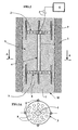
- the device according to the invention comprises at least one (and preferably several) vibrators V.
- the vibrators can be of any type: electromechanical, electromagnetic, hydraulic, etc.
- vibrators comprising at least one pillar of sensitive elements (piezoelectric or magnetostrictive) 1 rigidly associated with each of its opposite ends to a flag 2, 3 or plate .
- the pillar of sensitive elements is centered relative to the flags 2, 3 and covered by a deformable membrane 4.
- a connecting cable 5 connects the pillar 1 to a generator 6 of control signals.
- the vibrator V is placed in a cavity or well W and a coupling material 7 such as cement or concrete, for example, is injected into the well so that it is in intimate contact with the pillar 1 over its entire length and also with the opposite faces of each of the flags 2, 3.
- a coupling material 7 such as cement or concrete, for example
- the diameter of the flags 2, 3 must correspond substantially to the diameter of the cavity or the well W so as to obtain a maximum coupling surface.
- anchoring rods 9 of suitable length may be attached to the periphery of the horns 2, 3.
- each horn 2, 3 comprises, as shown, at least two parallel plates 2a, 2b connected to one another by anchoring rods 9.
- the external surface each plate 2a, 2b and also coupling rods 9 is preferably provided with relief inequalities, such as grooves.
- the space between the deformable tubular membrane 4 and the pillar of sensitive elements 1 may as shown be filled with a liquid L such as oil.
- the cement used for the coupling must dry without shrinking in order to guarantee a good coupling.
- the coupling of the vibrator with the formations can be improved if a chamber 11 is arranged in the wall of the well at each flag as indicated. fig.2b .
- a chamber 11 is arranged in the wall of the well at each flag as indicated. fig.2b .
- One solution is for example ( 2C ) to descend into the well at the planned location of burying the vibrator, a rod 12 carrying two windings 13 of detonating cord sufficiently spaced apart from each other, which is detonated.
- the device comprises several vibrators V1, V2, ..., Vn similar to that of the fig.1 or 5 , which are placed at intervals of each other along a well W.
- the vibrators are likewise embedded in one or more coupling material (s) 7, 10 ( fig.1 or fig.2a ).
- the procedure is as follows, for example.
- a seismic receiver R (hydrophone, geophone or preferably a combination of these two sensors) is preferably disposed substantially vertically of the well containing the vibrators or at a sufficiently small horizontal distance so that the travel times between each vibrator and this receiver R do not differ substantially from the vertical travel times.
- the receiver can be positioned in the well containing the vibrators and is connected to an acquisition and processing unit 15 arranged for example at the surface. If several receivers are positioned along the well under the vibrators, we will choose for example the deepest of them. It is also possible to use a surface receiver. The travel time ⁇ i of the waves between each vibrator Vi and this receiver R is measured beforehand.
- the assembly 15 controls the application of these time offsets to the vibrators via the control box 14.
- a seismic receiver such as a geophone G1.
- Each geophone is for example fixed to a support 16 disposed between two anchor bars 9.
- the geophones are respectively connected to the acquisition and processing unit 15 outside the well.
- the effective time of travel of the waves between each other is measured by any method of measuring the offset between signals, in particular by performing an intercorrelation between the signals delivered respectively by the geophones either in the time domain or in the frequency domain and the vibrator Vi is triggered taking into account this actual travel time. This measurement of the time shift can be performed by intercorrelation.
- the offsets calculated by the processing unit 15 are transmitted to the control unit 14 which consequently delays the different vibrators with respect to the first of them.
- Vibrators comprising a single central pillar 1 have been described. However, it is not within the scope of the invention to intercalate several pillars of piezoelectric sensitive elements between the two horns 2, 3.
Landscapes
- Engineering & Computer Science (AREA)
- Remote Sensing (AREA)
- Physics & Mathematics (AREA)
- Life Sciences & Earth Sciences (AREA)
- Acoustics & Sound (AREA)
- Environmental & Geological Engineering (AREA)
- Geology (AREA)
- General Life Sciences & Earth Sciences (AREA)
- General Physics & Mathematics (AREA)
- Geophysics (AREA)
- Geophysics And Detection Of Objects (AREA)
Claims (22)
- Vorrichtung zur Emission von Wellen in einer unterirdischen Formation, welche aufweist: mindestens einen Vibrator, der zwei Endplatten (2. 3) umfasst und in einem Schacht oder Hohlraum (W) positioniert ist, mindestens ein Antriebselement (1), das dafür eingerichtet ist, Schwingungen zu erzeugen und sie auf diese Endplatten zu übertragen, einen Generator (6) zum Zuführen periodischer Steuersignale zu dem Antriebselement und mindestens ein festes Material (7, 10), dadurch gekennzeichnet, dass der Vibrator in das feste Material (7, 10) eingebettet ist, welches seine Kopplung mit der unterirdischen Formation sicherstellt, wobei sich dieses Material mit den zwei Endplatten (2, 3) auf mindestens einem Teil jeder ihrer jeweiligen Seiten in Kontakt befindet.
- Vorrichtung nach Anspruch 1, dadurch gekennzeichnet, dass sie Verankerungsstangen (9) aufweist, die mit mindestens einer Endplatte (2. 3) verbunden sind, um die Kopplung des Vibrators mit der Masse (7, 10) des Kopplungsmaterials zu verstärken.
- Vorrichtung nach Anspruch 1, dadurch gekennzeichnet, dass jede Endplatte mindestens zwei Platten (2a, 2b) aufweist. die in einem Abstand voneinander angeordnet sind und durch Verankerungsstangen (9) miteinander verbunden sind.
- Vorrichtung nach Anspruch 2 oder 3, dadurch gekennzeichnet, dass die Außenfläche jeder Endplatte mit Unebenheiten des Reliefs wie etwa Rillen versehen ist, um die Kopplungsfläche der Vorrichtung mit dem Kopplungsmaterial (7, 10) zu vergrößern.
- Vorrichtung nach einem der Ansprüche 2 bis 4, dadurch gekennzeichnet. dass die Verankerungsstangen mit Unebenheiten des Reliefs versehen sind, um die Kopplungsfläche der Vorrichtung mit dem Kopplungsmaterial (7, 10) zu vergrößern,
- Vorrichtung nach Anspruch 1 oder 2, dadurch gekennzeichnet, dass die Endplatten (2, 3) gelocht sind, um das Eindringen des Kopplungsmaterials in den Raum zwischen den zwei Endplatten (2, 3) zu erleichtern.
- Vorrichtung nach einem der vorhergehenden Ansprüche, dadurch gekennzeichnet, dass sie einziges festes Kopplungsmaterial aufweist, welches derart verteilt ist, dass die Kopplung des Vibrators mit der Formation wenigstens an seinen gegenüberliegenden Enden sichergestellt wird.
- Vorrichtung nach Anspruch 7, dadurch gekennzeichnet, dass sie mindestens zwei Kopplungsmaterialien aufweist, wobei ein erstes Material (7a, 7b) auf zwei verschiedene Massen verteilt ist, um die Kopplung des Vibrators mit der Formation an seinen gegenüberliegenden Enden sicherzustellen, und ein zweites Material (10) zwischen den zwei Massen angeordnet ist.
- Vorrichtung nach einem der vorhergehenden Ansprüche, dadurch gekennzeichnet, dass sie mehrere Vibratoren (V1, ..., Vn) aufweist, die mit einem Signalgenerator (6) verbunden sind, wobei diese Vibratoren in Abständen voneinander entlang eines Schachtes (W) angeordnet sind und alle in mindestens ein Kopplungsmaterial (7, 10) eingebettet sind.
- Vorrichtung nach Anspruch 9, dadurch gekennzeichnet, dass sie ein Steuergehäuse (14) aufweist, das zwischen den Vibratoren (V1, ..., Vn) und dem Signalgenerator (6) angeordnet ist und ermöglicht, sie nacheinander auszulösen.
- Vorrichtung nach Anspruch 9 oder 10, dadurch gekennzeichnet, dass sie einen seismischen Empfänger (R) aufweist, der mit den Formationen, die den Schacht umgeben, in einer bestimmten Tiefe gekoppelt ist und mit einem Erfassungs- und Verarbeitungsblock (15) verbunden ist, der dafür eingerichtet ist, die Vibratoren der Reihe nach anzusteuern, um eine Emission zu erzielen, die hauptsächlich gemäß einem definierten Diagramm ausgerichtet ist.
- Vorrichtung nach Anspruch 9 oder 10, dadurch gekennzeichnet, dass sie seismische Empfänger (G1) aufweist, die den verschiedenen Vibratoren (V1) zugeordnet sind und mit einem Erfassungs- und Verarbeitungsblock (15) verbunden sind, der dafür eingerichtet ist, die Laufzeiten der Wellen zwischen den Positionen der verschiedenen Vibratoren zu bestimmen und sie der Reihe nach anzusteuern, um eine Emission zu erzielen, die hauptsächlich gemäß einem definierten Diagramm ausgerichtet ist.
- Vorrichtung nach Anspruch 2 und 12, dadurch gekennzeichnet, dass die Empfänger (G1) an Trägern (16) befestigt sind, die mit den Verankerungsstangen (9) fest verbunden sind.
- Vorrichtung nach einem der vorhergehenden Ansprüche, dadurch gekennzeichnet, dass jeder Vibrator eine Säule (1) von Sensorelementen aufweist, die von einer Schutzhülle (4) ummantelt ist, wobei sich das Kopplungsmaterial mit der Schutzhülle (4) und mit den zwei Endplatten (2, 3) auf mindestens einem Teil jeder ihrer jeweiligen Seiten in Kontakt befindet.
- Vorrichtung nach Anspruch 14, dadurch gekennzeichnet, dass der Raum zwischen der Hülle und der Säule von Sensorelementen mit einer Flüssigkeit wie etwa Öl gefüllt ist.
- Vorrichtung nach Anspruch 14, dadurch gekennzeichnet, dass die Säule (1) aus piezoelektrischen oder magnetostriktiven Sensorelementen besteht.
- Vorrichtung nach einem der Ansprüche 1 bis 13, dadurch gekennzeichnet, dass jedes Antriebselement vom elektromechanischen, elektromagnetischen oder hydraulischen Typ ist.
- Verfahren zum Erzeugen der Schwingungssignale in einer unterirdischen Formation gemäß einem orientierten Sendediagramm, dadurch gekennzeichnet, dass es umfasst:- die Anbringung mehrerer Vibratoren (V1, .... Vn) in ein und demselben Schacht (W), die jeweils zwei Endplatten (2, 3), mindestens ein Antriebselement (1), das dafür eingerichtet ist, Schwingungen zu erzeugen und sie auf diese Endplatten zu übertragen, und einen Generator (6) zum Zuführen periodischer Steuersignale zu dem Antriebselement umfassen, wobei jeder Vibrator in einem Schacht oder Hohlraum (W) positioniert ist und in mindestens ein festes Material (7, 10) eingebettet ist, das seine Kopplung mit der unterirdischen Formation sicherstellt, wobei sich dieses Material mit den zwei Endplatten (2, 3) auf mindestens einem Teil jeder ihrer jeweiligen Seiten in Kontakt befindet; und- das sequentielle Ansteuern der verschiedenen Vibratoren (V1...., Vn) über ein Steuergehäuse (10) mit Verschiebungen zwischen den jeweiligen Zeitpunkten der Auslösung, welche von den Abständen zwischen den Positionen der Vibratoren und von der Ausbreitungsgeschwindigkeit der Wellen in den Formationen, die den Schacht umgeben, abhängen, so dass eine gerichtete Emission erhalten wird.
- Verfahren nach Anspruch 18, dadurch gekennzeichnet, dass das sequentielle Ansteuern der Vibratoren das Anlegen von Steuersignalen mit fester Frequenz f an die Vibratoren umfasst, deren Phase Φi mit der Frequenz f und mit der besagten zeitlichen Verschiebung durch die Beziehung Φi = 2π.f.ti verknüpft ist
- Verfahren nach Anspruch 18, dadurch gekennzeichnet, dass das sequentielle Ansteuern der Vibratoren das Anlegen von Steuersignalen mit festen Frequenzen, die voneinander verschieden sind, an die verschiedenen Vibratoren umfasst, um ihre Trennung zu ermöglichen.
- Verfahren nach einem der Ansprüche 18 bis 20, dadurch gekennzeichnet, dass es die Kopplung eines seismischen Empfängers (R) mit der den Schacht umgebenden Formation und die vorherige Bestimmung der Durchlaufzeiten der Wellen jeweils zwischen jedem Vibrator und dem Empfänger (R) umfasst.
- Verfahren nach einem der Ansprüche 18 bis 20, dadurch gekennzeichnet, dass es die Zuordnung von Empfängern (R, G1), die mit einem Signalerfassungs- und -verarbeitungsblock (15) verbunden sind, zu den Vibratoren und die sequentielle Auslösung der verschiedenen Vibratoren mit Verschiebungen zwischen den jeweiligen Auslösezeitpunkten, die von dem besagten Block (15) berechnet werden, indem die Verschiebung zwischen den von den verschiedenen Empfängern erzeugten Signalen berechnet wird, umfasst.
Applications Claiming Priority (3)
| Application Number | Priority Date | Filing Date | Title |
|---|---|---|---|
| FR0211945A FR2845164B1 (fr) | 2002-09-26 | 2002-09-26 | Dispositif d'emission sismique dans une formation souterraine et methode pour sa mise en oeuvre |
| FR0211945 | 2002-09-26 | ||
| PCT/FR2003/002800 WO2004029661A1 (fr) | 2002-09-26 | 2003-09-24 | Dispositif d'emission sismique dans une formation souterraine et methode pour sa mise en oeuvre |
Publications (2)
| Publication Number | Publication Date |
|---|---|
| EP1546762A1 EP1546762A1 (de) | 2005-06-29 |
| EP1546762B1 true EP1546762B1 (de) | 2012-01-25 |
Family
ID=31985271
Family Applications (1)
| Application Number | Title | Priority Date | Filing Date |
|---|---|---|---|
| EP03798219A Expired - Lifetime EP1546762B1 (de) | 2002-09-26 | 2003-09-24 | Einrichtung zur seismischen emission in einer unterirdischen formation und verfahren zu ihrer implementierung |
Country Status (9)
| Country | Link |
|---|---|
| US (1) | US7420879B2 (de) |
| EP (1) | EP1546762B1 (de) |
| CN (1) | CN1300600C (de) |
| AT (1) | ATE543108T1 (de) |
| CA (1) | CA2499737C (de) |
| ES (1) | ES2378363T3 (de) |
| FR (1) | FR2845164B1 (de) |
| MX (1) | MXPA05003241A (de) |
| WO (1) | WO2004029661A1 (de) |
Families Citing this family (8)
| Publication number | Priority date | Publication date | Assignee | Title |
|---|---|---|---|---|
| ITUD20040207A1 (it) * | 2004-11-08 | 2005-02-08 | Istituto Naz Di Oceanografia E | Dispositivo di misura per un'apparecchiatura di perforazione |
| US7646670B2 (en) * | 2006-09-28 | 2010-01-12 | CGGVeritas Services (U.S.) Inc. | Autonomous ocean bottom seismic node recording device |
| FR2923615B1 (fr) * | 2007-11-12 | 2010-02-26 | Inst Francais Du Petrole | Source sismique permanente |
| FR2996009B1 (fr) * | 2012-09-26 | 2015-06-26 | Cggveritas Services Sa | Source d'onde sismique piezoelectrique volumetrique et procedes associes |
| AU2013270498A1 (en) | 2012-12-21 | 2014-07-10 | Cgg Services Sa | Volumetric and non-volumetric sources-based seismic survey and method |
| US10101477B2 (en) | 2013-12-17 | 2018-10-16 | Cgg Services Sas | System and method for performing seismic exploration with multiple acquisition systems |
| US10139513B2 (en) * | 2014-09-19 | 2018-11-27 | GreenPowerUSA Inc. | Distributed seismic source array |
| CN113640494B (zh) * | 2021-07-27 | 2023-04-07 | 清华大学 | 一种倾斜地层地下储库水力动力耦合灾害模拟装置及方法 |
Citations (1)
| Publication number | Priority date | Publication date | Assignee | Title |
|---|---|---|---|---|
| WO2002050572A1 (fr) * | 2000-12-21 | 2002-06-27 | Institut Francais Du Petrole | Dispositif pour engendrer des ondes elastiques focalisees dans un milieu materiel tel que le sous-sol, et methode pour sa mise en oeuvre |
Family Cites Families (9)
| Publication number | Priority date | Publication date | Assignee | Title |
|---|---|---|---|---|
| GB2185574B (en) * | 1986-01-17 | 1990-03-14 | Inst Francais Du Petrole | Process and device for installing seismic sensors inside a petroleum production well |
| CN1022139C (zh) * | 1986-03-18 | 1993-09-15 | 切夫伦研究公司 | 利用非破坏性井下地震源获得地质结构信息的方法 |
| US4834210A (en) * | 1987-12-21 | 1989-05-30 | Western Atlas International, Inc. | Apparatus for generating seismic waves |
| US4991685A (en) * | 1989-10-02 | 1991-02-12 | Atlantic Richfield Company | Downhole seismic source |
| US5360951A (en) * | 1993-10-13 | 1994-11-01 | Turpening Walter R | Earth reaction seismic source |
| FR2728973A1 (fr) * | 1994-12-29 | 1996-07-05 | Inst Francais Du Petrole | Methode et dispositif pour la surveillance sismique a long terme d'une zone souterraine renfermant des fluides |
| FR2766929B1 (fr) * | 1997-07-30 | 1999-10-22 | Daniel Odin | Source d'excitation sismique pour l'exploration d'une structure geologique, installation d'exploration sismique d'une structure geologique et equipement de surveillance de cavites geologiques |
| US6119804A (en) * | 1999-05-13 | 2000-09-19 | Owen; Thomas E. | Horizontally polarized shear-wave vibrator seismic source |
| US6488117B1 (en) * | 2001-08-24 | 2002-12-03 | Thomas E. Owen | Vertical-force vibrator seismic wave source |
-
2002
- 2002-09-26 FR FR0211945A patent/FR2845164B1/fr not_active Expired - Fee Related
-
2003
- 2003-09-24 US US10/529,374 patent/US7420879B2/en not_active Expired - Fee Related
- 2003-09-24 AT AT03798219T patent/ATE543108T1/de active
- 2003-09-24 WO PCT/FR2003/002800 patent/WO2004029661A1/fr active Application Filing
- 2003-09-24 EP EP03798219A patent/EP1546762B1/de not_active Expired - Lifetime
- 2003-09-24 MX MXPA05003241A patent/MXPA05003241A/es active IP Right Grant
- 2003-09-24 ES ES03798219T patent/ES2378363T3/es not_active Expired - Lifetime
- 2003-09-24 CN CNB038225328A patent/CN1300600C/zh not_active Expired - Fee Related
- 2003-09-24 CA CA2499737A patent/CA2499737C/fr not_active Expired - Fee Related
Patent Citations (1)
| Publication number | Priority date | Publication date | Assignee | Title |
|---|---|---|---|---|
| WO2002050572A1 (fr) * | 2000-12-21 | 2002-06-27 | Institut Francais Du Petrole | Dispositif pour engendrer des ondes elastiques focalisees dans un milieu materiel tel que le sous-sol, et methode pour sa mise en oeuvre |
Also Published As
| Publication number | Publication date |
|---|---|
| US20060131099A1 (en) | 2006-06-22 |
| CA2499737C (fr) | 2013-04-09 |
| FR2845164B1 (fr) | 2004-12-17 |
| EP1546762A1 (de) | 2005-06-29 |
| WO2004029661A1 (fr) | 2004-04-08 |
| ATE543108T1 (de) | 2012-02-15 |
| CN1300600C (zh) | 2007-02-14 |
| MXPA05003241A (es) | 2005-07-05 |
| CN1685248A (zh) | 2005-10-19 |
| ES2378363T3 (es) | 2012-04-11 |
| CA2499737A1 (fr) | 2004-04-08 |
| US7420879B2 (en) | 2008-09-02 |
| FR2845164A1 (fr) | 2004-04-02 |
Similar Documents
| Publication | Publication Date | Title |
|---|---|---|
| EP0148667B1 (de) | Verfahren und Gerät für geophysikalische Messungen in einem Bohrloch | |
| CA2183682C (fr) | Methode et dispositif pour la surveillance sismique a long terme d'une zone souterraine renfermant des fluides | |
| WO1998041885A1 (fr) | Emetteur et recepteur d'ondes acoustiques souterrains, procede d'emission/reception et exploration souterraine les utilisant | |
| EP1546762B1 (de) | Einrichtung zur seismischen emission in einer unterirdischen formation und verfahren zu ihrer implementierung | |
| CA2014045C (fr) | Methode et dispositif de prospection sismique dans des puits et notamment des puits devies | |
| EP0937997B1 (de) | Verfahren zur permanenten seismischen Überwachung von untererdischen Formationen | |
| EP1041403B1 (de) | Kompakter seismischer Vibrator und Verfahren zur seiner Verwendung in seismische Überwachung und Prospektion | |
| FR2703470A1 (fr) | Dispositif d'émission-réception permanent pour la surveillance d'une formation souterraine et méthode de mise en Óoeuvre. | |
| CA2431812C (fr) | Dispositif pour engendrer des ondes elastiques focalisees dans un milieu materiel tel que le sous-sol, et methode pour sa mise en oeuvre | |
| EP1459103B1 (de) | Mobiles seismisches emissionssystem mit fixen kopplungsvorrichtungen und methode dafür | |
| FR2616919A1 (fr) | Procede et dispositif pour la prospection sismique d'un milieu, a partir d'ondes induites creees artificiellement dans un puits | |
| CA2042565C (fr) | Systeme de reception d'ondes acoustiques pour puits permettant un decouplage mecanique des capteurs | |
| Lebedev et al. | Coherent seismoacoustics | |
| EP0458947A1 (de) | Verfahren und vorrichtung zur datenerfassung von seismischen messwerten aus bohrlöchern in zwei entgegengesetzten richtungen. | |
| Paulsson et al. | Field test of the borehole clamped, hydraulic vibrator | |
| Matsubara et al. | High-resolution shallow seismic reflection profiling using portable vibrator | |
| Rodriguez et al. | Reservoir Monitoring Using Permanent Sources and Vertical Receiver Antennae: The Cere-la-Ronde Case Study |
Legal Events
| Date | Code | Title | Description |
|---|---|---|---|
| PUAI | Public reference made under article 153(3) epc to a published international application that has entered the european phase |
Free format text: ORIGINAL CODE: 0009012 |
|
| 17P | Request for examination filed |
Effective date: 20050426 |
|
| AK | Designated contracting states |
Kind code of ref document: A1 Designated state(s): AT BE BG CH CY CZ DE DK EE ES FI FR GB GR HU IE IT LI LU MC NL PT RO SE SI SK TR |
|
| 17Q | First examination report despatched |
Effective date: 20061115 |
|
| RAP1 | Party data changed (applicant data changed or rights of an application transferred) |
Owner name: INSTITUT FRANCAIS DU PETROLE Owner name: GDF SUEZ Owner name: CGGVERITAS SERVICES SA |
|
| GRAP | Despatch of communication of intention to grant a patent |
Free format text: ORIGINAL CODE: EPIDOSNIGR1 |
|
| GRAS | Grant fee paid |
Free format text: ORIGINAL CODE: EPIDOSNIGR3 |
|
| GRAA | (expected) grant |
Free format text: ORIGINAL CODE: 0009210 |
|
| AK | Designated contracting states |
Kind code of ref document: B1 Designated state(s): AT BE BG CH CY CZ DE DK EE ES FI FR GB GR HU IE IT LI LU MC NL PT RO SE SI SK TR |
|
| REG | Reference to a national code |
Ref country code: GB Ref legal event code: FG4D Free format text: NOT ENGLISH |
|
| REG | Reference to a national code |
Ref country code: CH Ref legal event code: EP |
|
| REG | Reference to a national code |
Ref country code: AT Ref legal event code: REF Ref document number: 543108 Country of ref document: AT Kind code of ref document: T Effective date: 20120215 |
|
| REG | Reference to a national code |
Ref country code: IE Ref legal event code: FG4D |
|
| REG | Reference to a national code |
Ref country code: NL Ref legal event code: T3 |
|
| REG | Reference to a national code |
Ref country code: DE Ref legal event code: R096 Ref document number: 60339851 Country of ref document: DE Effective date: 20120322 |
|
| REG | Reference to a national code |
Ref country code: ES Ref legal event code: FG2A Ref document number: 2378363 Country of ref document: ES Kind code of ref document: T3 Effective date: 20120411 |
|
| PG25 | Lapsed in a contracting state [announced via postgrant information from national office to epo] |
Ref country code: BG Free format text: LAPSE BECAUSE OF FAILURE TO SUBMIT A TRANSLATION OF THE DESCRIPTION OR TO PAY THE FEE WITHIN THE PRESCRIBED TIME-LIMIT Effective date: 20120425 |
|
| REG | Reference to a national code |
Ref country code: IE Ref legal event code: FD4D |
|
| PG25 | Lapsed in a contracting state [announced via postgrant information from national office to epo] |
Ref country code: PT Free format text: LAPSE BECAUSE OF FAILURE TO SUBMIT A TRANSLATION OF THE DESCRIPTION OR TO PAY THE FEE WITHIN THE PRESCRIBED TIME-LIMIT Effective date: 20120525 Ref country code: FI Free format text: LAPSE BECAUSE OF FAILURE TO SUBMIT A TRANSLATION OF THE DESCRIPTION OR TO PAY THE FEE WITHIN THE PRESCRIBED TIME-LIMIT Effective date: 20120125 Ref country code: GR Free format text: LAPSE BECAUSE OF FAILURE TO SUBMIT A TRANSLATION OF THE DESCRIPTION OR TO PAY THE FEE WITHIN THE PRESCRIBED TIME-LIMIT Effective date: 20120426 |
|
| REG | Reference to a national code |
Ref country code: AT Ref legal event code: MK05 Ref document number: 543108 Country of ref document: AT Kind code of ref document: T Effective date: 20120125 |
|
| PG25 | Lapsed in a contracting state [announced via postgrant information from national office to epo] |
Ref country code: CY Free format text: LAPSE BECAUSE OF FAILURE TO SUBMIT A TRANSLATION OF THE DESCRIPTION OR TO PAY THE FEE WITHIN THE PRESCRIBED TIME-LIMIT Effective date: 20120125 |
|
| PG25 | Lapsed in a contracting state [announced via postgrant information from national office to epo] |
Ref country code: EE Free format text: LAPSE BECAUSE OF FAILURE TO SUBMIT A TRANSLATION OF THE DESCRIPTION OR TO PAY THE FEE WITHIN THE PRESCRIBED TIME-LIMIT Effective date: 20120125 Ref country code: IE Free format text: LAPSE BECAUSE OF FAILURE TO SUBMIT A TRANSLATION OF THE DESCRIPTION OR TO PAY THE FEE WITHIN THE PRESCRIBED TIME-LIMIT Effective date: 20120125 Ref country code: SE Free format text: LAPSE BECAUSE OF FAILURE TO SUBMIT A TRANSLATION OF THE DESCRIPTION OR TO PAY THE FEE WITHIN THE PRESCRIBED TIME-LIMIT Effective date: 20120125 Ref country code: DK Free format text: LAPSE BECAUSE OF FAILURE TO SUBMIT A TRANSLATION OF THE DESCRIPTION OR TO PAY THE FEE WITHIN THE PRESCRIBED TIME-LIMIT Effective date: 20120125 Ref country code: RO Free format text: LAPSE BECAUSE OF FAILURE TO SUBMIT A TRANSLATION OF THE DESCRIPTION OR TO PAY THE FEE WITHIN THE PRESCRIBED TIME-LIMIT Effective date: 20120125 Ref country code: CZ Free format text: LAPSE BECAUSE OF FAILURE TO SUBMIT A TRANSLATION OF THE DESCRIPTION OR TO PAY THE FEE WITHIN THE PRESCRIBED TIME-LIMIT Effective date: 20120125 Ref country code: SI Free format text: LAPSE BECAUSE OF FAILURE TO SUBMIT A TRANSLATION OF THE DESCRIPTION OR TO PAY THE FEE WITHIN THE PRESCRIBED TIME-LIMIT Effective date: 20120125 |
|
| PG25 | Lapsed in a contracting state [announced via postgrant information from national office to epo] |
Ref country code: IT Free format text: LAPSE BECAUSE OF FAILURE TO SUBMIT A TRANSLATION OF THE DESCRIPTION OR TO PAY THE FEE WITHIN THE PRESCRIBED TIME-LIMIT Effective date: 20120125 Ref country code: SK Free format text: LAPSE BECAUSE OF FAILURE TO SUBMIT A TRANSLATION OF THE DESCRIPTION OR TO PAY THE FEE WITHIN THE PRESCRIBED TIME-LIMIT Effective date: 20120125 |
|
| PLBE | No opposition filed within time limit |
Free format text: ORIGINAL CODE: 0009261 |
|
| STAA | Information on the status of an ep patent application or granted ep patent |
Free format text: STATUS: NO OPPOSITION FILED WITHIN TIME LIMIT |
|
| 26N | No opposition filed |
Effective date: 20121026 |
|
| PG25 | Lapsed in a contracting state [announced via postgrant information from national office to epo] |
Ref country code: AT Free format text: LAPSE BECAUSE OF FAILURE TO SUBMIT A TRANSLATION OF THE DESCRIPTION OR TO PAY THE FEE WITHIN THE PRESCRIBED TIME-LIMIT Effective date: 20120125 |
|
| REG | Reference to a national code |
Ref country code: DE Ref legal event code: R097 Ref document number: 60339851 Country of ref document: DE Effective date: 20121026 |
|
| BERE | Be: lapsed |
Owner name: INSTITUT FRANCAIS DU PETROLE Effective date: 20120930 Owner name: CGGVERITAS SERVICES SA Effective date: 20120930 Owner name: GDF SUEZ Effective date: 20120930 |
|
| PG25 | Lapsed in a contracting state [announced via postgrant information from national office to epo] |
Ref country code: MC Free format text: LAPSE BECAUSE OF NON-PAYMENT OF DUE FEES Effective date: 20120930 |
|
| REG | Reference to a national code |
Ref country code: CH Ref legal event code: PL |
|
| GBPC | Gb: european patent ceased through non-payment of renewal fee |
Effective date: 20120924 |
|
| PG25 | Lapsed in a contracting state [announced via postgrant information from national office to epo] |
Ref country code: LI Free format text: LAPSE BECAUSE OF NON-PAYMENT OF DUE FEES Effective date: 20120930 Ref country code: BE Free format text: LAPSE BECAUSE OF NON-PAYMENT OF DUE FEES Effective date: 20120930 Ref country code: CH Free format text: LAPSE BECAUSE OF NON-PAYMENT OF DUE FEES Effective date: 20120930 Ref country code: GB Free format text: LAPSE BECAUSE OF NON-PAYMENT OF DUE FEES Effective date: 20120924 |
|
| PG25 | Lapsed in a contracting state [announced via postgrant information from national office to epo] |
Ref country code: TR Free format text: LAPSE BECAUSE OF FAILURE TO SUBMIT A TRANSLATION OF THE DESCRIPTION OR TO PAY THE FEE WITHIN THE PRESCRIBED TIME-LIMIT Effective date: 20120125 |
|
| PG25 | Lapsed in a contracting state [announced via postgrant information from national office to epo] |
Ref country code: LU Free format text: LAPSE BECAUSE OF NON-PAYMENT OF DUE FEES Effective date: 20120924 |
|
| PG25 | Lapsed in a contracting state [announced via postgrant information from national office to epo] |
Ref country code: HU Free format text: LAPSE BECAUSE OF FAILURE TO SUBMIT A TRANSLATION OF THE DESCRIPTION OR TO PAY THE FEE WITHIN THE PRESCRIBED TIME-LIMIT Effective date: 20030924 |
|
| REG | Reference to a national code |
Ref country code: FR Ref legal event code: PLFP Year of fee payment: 14 |
|
| PGFP | Annual fee paid to national office [announced via postgrant information from national office to epo] |
Ref country code: DE Payment date: 20160921 Year of fee payment: 14 |
|
| PGFP | Annual fee paid to national office [announced via postgrant information from national office to epo] |
Ref country code: ES Payment date: 20160916 Year of fee payment: 14 |
|
| REG | Reference to a national code |
Ref country code: FR Ref legal event code: PLFP Year of fee payment: 15 |
|
| PGFP | Annual fee paid to national office [announced via postgrant information from national office to epo] |
Ref country code: NL Payment date: 20170921 Year of fee payment: 15 |
|
| REG | Reference to a national code |
Ref country code: DE Ref legal event code: R119 Ref document number: 60339851 Country of ref document: DE |
|
| PG25 | Lapsed in a contracting state [announced via postgrant information from national office to epo] |
Ref country code: DE Free format text: LAPSE BECAUSE OF NON-PAYMENT OF DUE FEES Effective date: 20180404 |
|
| REG | Reference to a national code |
Ref country code: FR Ref legal event code: PLFP Year of fee payment: 16 |
|
| REG | Reference to a national code |
Ref country code: ES Ref legal event code: FD2A Effective date: 20181018 |
|
| PG25 | Lapsed in a contracting state [announced via postgrant information from national office to epo] |
Ref country code: ES Free format text: LAPSE BECAUSE OF NON-PAYMENT OF DUE FEES Effective date: 20170925 |
|
| REG | Reference to a national code |
Ref country code: NL Ref legal event code: MM Effective date: 20181001 |
|
| PG25 | Lapsed in a contracting state [announced via postgrant information from national office to epo] |
Ref country code: NL Free format text: LAPSE BECAUSE OF NON-PAYMENT OF DUE FEES Effective date: 20181001 |
|
| PGFP | Annual fee paid to national office [announced via postgrant information from national office to epo] |
Ref country code: FR Payment date: 20210921 Year of fee payment: 19 |
|
| PG25 | Lapsed in a contracting state [announced via postgrant information from national office to epo] |
Ref country code: FR Free format text: LAPSE BECAUSE OF NON-PAYMENT OF DUE FEES Effective date: 20220930 |