EP1546699B1 - Pulsed discharge ionization source for miniature ion mobility spectrometers - Google Patents
Pulsed discharge ionization source for miniature ion mobility spectrometers Download PDFInfo
- Publication number
- EP1546699B1 EP1546699B1 EP03816115.4A EP03816115A EP1546699B1 EP 1546699 B1 EP1546699 B1 EP 1546699B1 EP 03816115 A EP03816115 A EP 03816115A EP 1546699 B1 EP1546699 B1 EP 1546699B1
- Authority
- EP
- European Patent Office
- Prior art keywords
- drift
- ion
- chamber
- corona discharge
- instrument
- Prior art date
- Legal status (The legal status is an assumption and is not a legal conclusion. Google has not performed a legal analysis and makes no representation as to the accuracy of the status listed.)
- Expired - Lifetime
Links
Images

Classifications
-
- H—ELECTRICITY
- H01—ELECTRIC ELEMENTS
- H01J—ELECTRIC DISCHARGE TUBES OR DISCHARGE LAMPS
- H01J49/00—Particle spectrometers or separator tubes
- H01J49/02—Details
- H01J49/10—Ion sources; Ion guns
- H01J49/16—Ion sources; Ion guns using surface ionisation, e.g. field-, thermionic- or photo-emission
- H01J49/168—Ion sources; Ion guns using surface ionisation, e.g. field-, thermionic- or photo-emission field ionisation, e.g. corona discharge
-
- G—PHYSICS
- G01—MEASURING; TESTING
- G01N—INVESTIGATING OR ANALYSING MATERIALS BY DETERMINING THEIR CHEMICAL OR PHYSICAL PROPERTIES
- G01N27/00—Investigating or analysing materials by the use of electric, electrochemical, or magnetic means
- G01N27/62—Investigating or analysing materials by the use of electric, electrochemical, or magnetic means by investigating the ionisation of gases, e.g. aerosols; by investigating electric discharges, e.g. emission of cathode
- G01N27/622—Ion mobility spectrometry
Definitions
- IMS Ion mobility spectrometry
- VOCs chemical warfare agents
- CW agents chemical warfare agents
- IMS ion mobility spectrometry
- IMS ion mobility spectrometry
- Explosives generally have high electron affinities and drugs and chemical warfare (CW) agents have high proton affinities.
- IMS ion mobility spectrometer
- negative and positive ions of these samples will be preferentially formed.
- IMS ion mobility spectrometer
- Some commercial ion mobility spectrometers are available for detecting the above chemicals.
- a typical problem for commercial hand-held IMS is loss of sensitivity.
- the sensitivity of a desktop size IMS detector now used in airports is about 1 nanogram for explosives.
- the sensitivity of a smaller, handheld version would be reduced more than 100 times.
- the main reason for the reduced sensitivity is the use of a nickel-63 (Ni 63 ) radioactive source for ionization.
- Nickel-63 emits electrons with 67 keV kinetic energy.
- the low stopping power of the high-energy electrons in gases generates less ions in the small volume of the miniature IMS ionization chamber, resulting in the low sensitivity.
- a nickel-63 source has potential hazards due to its radioactive nature.
- pulses with various polarities, amplitudes, and widths are generated by a RF oscillator and are used to produce ions through a corona discharge. Certain features of these pulses are undefined, which tends to limit the performance of this kind of spectrometer.
- An ion gate is used to control ions entering an ion mobility channel and the electronics require that the device have extra size.
- the invention is a method and apparatus for providing a pulsed discharge ionization source particularly designed for miniature ion mobility spectrometers (IMS), but also usable in other analytical instruments.
- the invention uses a pulse to generate a corona around a tip of non-radioactive (non-doped) material to generate ions from a sample gas and to signal the start of ion motion.
- the applied potential comprises a pulse component and a dc base voltage component, which reduces the pulse component. This reduces noise and power consumption.
- Miniaturized ion mobility spectrometers equipped with the pulsed discharge ionization source of the present invention have the following advantages: (1) high sensitivity because the ions are concentrated in a very small volume, (2) the use of an ion gate and its associated electronics is unnecessary, and (3) a high dynamic range is available because the ionization rate can be adjusted.
- the present invention provides a method and an apparatus in which ions are generated in a highly confined space and time, which results in high sensitivity for miniature IMS detectors.
- a processor-based electronic control enables timing of the initial ion motion with the ionization pulse. This provides a device without the need for an ion extract gate for ions entering a drift chamber. This reduces the size of the drift chamber body, the electronics control package, and power consumption.
- the invention also provides for increased dynamic range by adjusting the pulse height or by adjusting the DC bias.
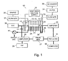
- the present invention is practiced in a miniature ion mobility spectrometer (IMS) 10 employing a pulsed corona discharge ion source as shown in Fig. 1 .
- IMS ion mobility spectrometer
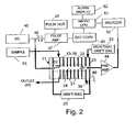
- Fig. 2 shows a second miniaturized embodiment of the apparatus featuring a microelectronic CPU 51.
- the device has a cylindrical body 11 comprised of ten (10) stacked, annular metal electrodes 12-19, 22 and 23 which are separated by annular spacers 21 (5-mm thick and 8 mm ID) of a dielectric material such as Teflon.
- This forms a drift channel 24 which can be in the range from 1.7 mm-2.5 mm in diameter and 35-50 mm in effective length.
- the drift channel is specifically 2.5 mm in diameter and 47 mm in length, respectively.
- the first electrode 12 is biased with a power supply 20 to provide an ion drift voltage, with the voltage being distributed to the intermediate electrodes 13-19, 22 and 23 through these resistors.
- the last electrode 23 is connected to an electrical ground 40.
- the next to the last electrode 22 is connected to a 470-pf capacitor 39 to suppress transients.
- An ion detector electrode 25 is located in the drift chamber 24 between the last electrode 23 and the next to last electrode 22. Positive or negative potentials can be applied to the detection electrode 25 for detecting positive and negative ions, respectively.
- a nickel-tipped electrode 26 of non-radioactive (non-doped) material with an end radius of curvature of approximately 25 ⁇ m is mounted at the entrance of the drift chamber 24.
- the second drift channel electrode 13 is used as the counter electrode for corona discharge with the distance to the tip 26 being larger than the threshold distance for discharge zone as illustrated in Fig. 5 .
- a sample gas is supplied from reservoir 38 in Fig. 1 through a flow meter 37 to an inlet into the corona discharge end of the drift chamber 24.
- a carrier gas in this case, nitrogen, is supplied from a source 35 through a filter 34 and a second flow meter 33 to an inlet into the detection end of the drift chamber 24. These gases exit the drift chamber through valve 41 and outlet 42.
- a sample gas is received from a source 43, while dry air enters from a supply 53 into an entrance at the opposite end of the drift chamber 24.
- the dry air includes both drift gas and reactant gas. All of these gases exit from exit 42.
- a corona is produced at the electrode 26 by applying an electrical pulse having a width of from 40 ns to 100 ⁇ s, a pulse height varying from 0.2-3.3 kV and a repetition rate (frequency) of 20 Hz.
- the pulse is generated as a base dc voltage component originating at a high voltage source 36 and a varying pulse component generated by a pulse generator comprising high voltage source 29, amplifier 28 and pulse generator 27, which generates pulses on the order of 5 volts before they are amplified. These pulses are summed with a base dc voltage through capacitor C1.
- the resulting amplified high-voltage pulse is applied to the corona tip electrode 26, which is seen in Fig. 1 .
- ions are generated in the vicinity of the tip 26. After the pulse, the ions move along the drift channel 24 through the carrier gases under the influence of the drift field bias provided by voltage supply 20.
- the corona discharge pulse also provides a start signal for timing the ion mobility movements.
- ions are separated according to their travel time to reach the ion detector 25 located at the end of the channel 24. There, an ion current is produced and is transmitted to a current amplifier 30 connected to electrode 25.
- the time difference between the start signal and arrival of ions is detected by a time-to-digital converter (TDC) 31 and is transmitted to a computer 32 for analysis. If a digital oscilloscope 31 is used instead of time-to-digital converter 31, the start pulse triggers the oscilloscope.
- the ion arrival signal is recorded by the scope and sent to the computer 32.
- the detector 25 is connected to an amplifier 30 in Fig. 1 which amplifies the signals.
- the oscilloscope is connected to an Apple Macintosh computer 32 running a Labview application program in Fig. 1 . This is a lab prototype embodiment for demonstrating the operation of the invention.
- Fig. 2 the components in Fig. 1 are designed for reduced size in a commercial embodiment.
- Ion mobility spectra of both positive and negative ions were measured as a function of pulse width. For positive ions, the ion current increased with pulse width and saturated. For negative ions, the ion current peaked rapidly and then decayed with increased pulse width.
- Ion mobility spectra of negative ions produced by pulsed corona discharge and by ionization of air were measured as a function of drift bias voltage from -600 VDC to -1700 VDC as seen in Fig. 3 .
- the pulses had 1.08 ⁇ s width and +2600V amplitude.
- the sample air was at atmospheric pressure and room temperature.
- the drift gas was N 2 , which was fed from a source 35 through a filter 36 and flow meter 37 at the detector end of the IMS channel 24 with a flow rate of 20 sccm (standard cubic centimeter per minute).
- FIG. 4 A typical mobility spectrum of positive ions generated by pulsed corona discharge ionization of air is shown in Fig. 4 .
- the pulse potential applied to the tip 26 was also positive, the same polarity as used for generating negative ions, with a height of 3100 VDC and a width of 14.5 ⁇ s.
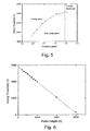
- the corona discharge properties depend on the distance between the tip 26 and the counter electrode 13.
- the counter electrode can be either a ring or a tip. This is illustrated in Fig. 5 .
- a threshold of potential about 1900 VDC was reached.
- spark breakdown occurred, which preceded the establishment of a stable corona.
- the voltage threshold was found to increase as a function of distance, as shown in Fig. 5 , up to 2400 volts at 1.96 mm. Stable corona discharge conditions could not be found in this distance range.
- corona discharge occurred at a threshold that was a function of the drift bias.
- Corona discharge was also generated by a combination of a base dc potential in combination with a pulsed voltage potential.
- a dc voltage supply 36 is connected to a dc pulse generator 27, an amplifier 28 and a second dc supply 29 through capacitor C1.
- dc voltage supply 45 is connected to a pulse amplifier 47 and a pulse height control circuit 48 through a capacitor 46.
- the pulse is commanded by the microelectronic CPU 51 through a digital-to-analog converter 49.
- the base dc potential which varied from 0 to 3000 volts, was superimposed on the pulsed potential.
- the combined potentials permit independent variation of the dc potential, pulse height, and pulse width to the corona tip.
- the ion mobility spectrum current can be measured as a function of dc bias voltage.
- the current exhibited a threshold for the dc bias and increased to a saturation level.
- the dc threshold was found to linearly decrease from 3000 VDC to 200 VDC as the pulse height was increased from 200 VDC to 3000 VDC, as shown in Fig. 6 . Therefore, ions could be generated with lower voltage pulses if the dc base voltage were raised.
- the detector 25 in Fig. 2 is connected in close proximity to an amplifier 44 which amplified the small signal. This signal is then digitized by digitizer 50 to filter noise, and is then read by the microelectronic CPU 51. For a specific substance, thresholds are set, and if a threshold is exceeded, a visual indication is provided to a user through an alarm display 52, such as by illuminating an icon or changing the color of an object on a display screen.
- the electronic circuits 20 and 44-52 in Fig. 2 can be made quite compact and can be mounted on circuit boards. These can be packaged with the drift chamber body 11 in a package the size of a lightweight notebook computer of the type having a titanium case.
- the pulsed corona ionization source of the present invention eliminates the need for the ion gate of the prior art near the ion source. It also provides for a smaller drift chamber and a smaller body for housing the drift chamber. The invention also provides a method for timing the movement of the ions between the source and the detector. The use of a dc voltage comprising a pulse element and a base voltage element reduces the pulse component, which reduces noise and power consumption.
Description
- The field of the invention is ion mobility spectrometers. Ion mobility spectrometry (IMS) is an important method for detecting drugs, explosives, VOCs, and chemical warfare agents at ambient pressure. Explosives generally have high electron affinities and drugs and chemical warfare (CW) agents have high proton affinities. When these chemicals enter the reactor of an ion mobility spectrometer (IMS), negative and positive ions of these samples will be preferentially formed. Such a preference allows a high sensitivity of IMS technology in detecting trace explosives, drugs, and CW agents. Some commercial ion mobility spectrometers are available for detecting the above chemicals.
- Miniaturization of such instruments provides advantageous applications in the field. However, a typical problem for commercial hand-held IMS is loss of sensitivity. For example, the sensitivity of a desktop size IMS detector now used in airports, is about 1 nanogram for explosives. The sensitivity of a smaller, handheld version, would be reduced more than 100 times. The main reason for the reduced sensitivity is the use of a nickel-63 (Ni63) radioactive source for ionization. Nickel-63 emits electrons with 67 keV kinetic energy. The low stopping power of the high-energy electrons in gases generates less ions in the small volume of the miniature IMS ionization chamber, resulting in the low sensitivity. In addition, a nickel-63 source has potential hazards due to its radioactive nature. An example of an ion-producing device with a nickel-63 radioactive source is disclosed in
Turner et al., U.S. Pat. No. 6,225,623, issued May 1, 2001 . For general information concerning the principles of ion mobility spectrometry, reference is made to Eiceman, G.A. and Karpas, Z., "Ion Mobility Spectrometry," CRC Press, Boca Raton FL, USA, 1994. - In
Taylor et al., U.S. Pat. No. 5,684,300, issued Nov. 4, 1997 , andPCT Pub. No. WO 93/11554, published June 10, 1993 - The invention is a method and apparatus for providing a pulsed discharge ionization source particularly designed for miniature ion mobility spectrometers (IMS), but also usable in other analytical instruments. The invention uses a pulse to generate a corona around a tip of non-radioactive (non-doped) material to generate ions from a sample gas and to signal the start of ion motion.
- In a further aspect of the invention, the applied potential comprises a pulse component and a dc base voltage component, which reduces the pulse component. This reduces noise and power consumption.
- Miniaturized ion mobility spectrometers equipped with the pulsed discharge ionization source of the present invention have the following advantages: (1) high sensitivity because the ions are concentrated in a very small volume, (2) the use of an ion gate and its associated electronics is unnecessary, and (3) a high dynamic range is available because the ionization rate can be adjusted.
- The present invention provides a method and an apparatus in which ions are generated in a highly confined space and time, which results in high sensitivity for miniature IMS detectors. A processor-based electronic control enables timing of the initial ion motion with the ionization pulse. This provides a device without the need for an ion extract gate for ions entering a drift chamber. This reduces the size of the drift chamber body, the electronics control package, and power consumption. The invention also provides for increased dynamic range by adjusting the pulse height or by adjusting the DC bias.
- Other objects and advantages of the invention, besides those discussed above, will be apparent to those of ordinary skill in the art from the description of the preferred embodiments which follows. In the description reference is made to the accompanying drawings, which form a part hereof, and which illustrate examples of the invention. Such examples, however are not exhaustive of the various embodiments of the invention, and therefore reference is made to the claims which follow the description for determining the scope of the invention.
-
-
Fig. 1 is a schematic view of a first embodiment of an apparatus for practicing the method of the present invention; -
Fig. 2 is a schematic view of a second embodiment of an apparatus for practicing the method of the present invention; -
Fig. 3 is a graph of ion detection current vs. time vs. dc bias voltage; -
Fig. 4 is a graph of ion detection current vs. drift time for moist air and for nitrogen supplied to the drift chamber; -
Fig. 5 is a graph of arcing threshold voltage vs. distance between two electrodes for generating an ion-producing corona; and -
Fig. 6 is a graph of arcing threshold voltage vs. pulse height for generating an ion-producing corona. - Referring to
Fig. 1 , the present invention is practiced in a miniature ion mobility spectrometer (IMS) 10 employing a pulsed corona discharge ion source as shown inFig. 1 . -
Fig. 2 shows a second miniaturized embodiment of the apparatus featuring amicroelectronic CPU 51. - In
Figs. 1 and2 , the device has acylindrical body 11 comprised of ten (10) stacked, annular metal electrodes 12-19, 22 and 23 which are separated by annular spacers 21 (5-mm thick and 8 mm ID) of a dielectric material such as Teflon. This forms adrift channel 24 which can be in the range from 1.7 mm-2.5 mm in diameter and 35-50 mm in effective length. InFig. 1 , the drift channel is specifically 2.5 mm in diameter and 47 mm in length, respectively. - Nine miniature resistors (not shown), each with 2 MΩ resistance, 1% tolerance, are connected between the electrodes 12-19, 22 and 23 to form a voltage divider. The
first electrode 12 is biased with apower supply 20 to provide an ion drift voltage, with the voltage being distributed to the intermediate electrodes 13-19, 22 and 23 through these resistors. Thelast electrode 23 is connected to anelectrical ground 40. The next to thelast electrode 22 is connected to a 470-pf capacitor 39 to suppress transients. Anion detector electrode 25 is located in thedrift chamber 24 between thelast electrode 23 and the next tolast electrode 22. Positive or negative potentials can be applied to thedetection electrode 25 for detecting positive and negative ions, respectively. - A nickel-tipped electrode 26 of non-radioactive (non-doped) material with an end radius of curvature of approximately 25 µm is mounted at the entrance of the
drift chamber 24. The second drift channel electrode 13 is used as the counter electrode for corona discharge with the distance to the tip 26 being larger than the threshold distance for discharge zone as illustrated inFig. 5 . The corona-producing tip 26, together with the second electrode 13 of the IMS channel, formed a tip-ring corona discharge element. - A sample gas is supplied from reservoir 38 in
Fig. 1 through aflow meter 37 to an inlet into the corona discharge end of thedrift chamber 24. A carrier gas, in this case, nitrogen, is supplied from asource 35 through afilter 34 and asecond flow meter 33 to an inlet into the detection end of thedrift chamber 24. These gases exit the drift chamber throughvalve 41 andoutlet 42. InFig. 2 , where parts similar toFig. 1 have the same number, a sample gas is received from asource 43, while dry air enters from asupply 53 into an entrance at the opposite end of thedrift chamber 24. The dry air includes both drift gas and reactant gas. All of these gases exit fromexit 42. - A corona is produced at the electrode 26 by applying an electrical pulse having a width of from 40 ns to 100 µs, a pulse height varying from 0.2-3.3 kV and a repetition rate (frequency) of 20 Hz. The pulse is generated as a base dc voltage component originating at a
high voltage source 36 and a varying pulse component generated by a pulse generator comprisinghigh voltage source 29,amplifier 28 andpulse generator 27, which generates pulses on the order of 5 volts before they are amplified. These pulses are summed with a base dc voltage through capacitor C1. The resulting amplified high-voltage pulse is applied to the corona tip electrode 26, which is seen inFig. 1 . During the high voltage pulse, ions are generated in the vicinity of the tip 26. After the pulse, the ions move along thedrift channel 24 through the carrier gases under the influence of the drift field bias provided byvoltage supply 20. - The corona discharge pulse also provides a start signal for timing the ion mobility movements. For each pulse, ions are separated according to their travel time to reach the
ion detector 25 located at the end of thechannel 24. There, an ion current is produced and is transmitted to acurrent amplifier 30 connected toelectrode 25. The time difference between the start signal and arrival of ions is detected by a time-to-digital converter (TDC) 31 and is transmitted to acomputer 32 for analysis. If adigital oscilloscope 31 is used instead of time-to-digital converter 31, the start pulse triggers the oscilloscope. The ion arrival signal is recorded by the scope and sent to thecomputer 32. - The
detector 25 is connected to anamplifier 30 inFig. 1 which amplifies the signals. The oscilloscope is connected to anApple Macintosh computer 32 running a Labview application program inFig. 1 . This is a lab prototype embodiment for demonstrating the operation of the invention. InFig. 2 , the components inFig. 1 are designed for reduced size in a commercial embodiment. - Ion mobility spectra of both positive and negative ions were measured as a function of pulse width. For positive ions, the ion current increased with pulse width and saturated. For negative ions, the ion current peaked rapidly and then decayed with increased pulse width.
- Ion mobility spectra of negative ions produced by pulsed corona discharge and by ionization of air were measured as a function of drift bias voltage from -600 VDC to -1700 VDC as seen in
Fig. 3 . The pulses had 1.08 µs width and +2600V amplitude. The sample air was at atmospheric pressure and room temperature. The drift gas was N2, which was fed from asource 35 through afilter 36 and flowmeter 37 at the detector end of theIMS channel 24 with a flow rate of 20 sccm (standard cubic centimeter per minute). - A typical mobility spectrum of positive ions generated by pulsed corona discharge ionization of air is shown in
Fig. 4 . For producing positive ions, the pulse potential applied to the tip 26 was also positive, the same polarity as used for generating negative ions, with a height of 3100 VDC and a width of 14.5 µs. - The corona discharge properties depend on the distance between the tip 26 and the counter electrode 13. The counter electrode can be either a ring or a tip. This is illustrated in
Fig. 5 . For distances less than 1.96 mm, no ionization occurred until a threshold of potential, about 1900 VDC was reached. At and above the threshold, spark breakdown occurred, which preceded the establishment of a stable corona. The voltage threshold was found to increase as a function of distance, as shown inFig. 5 , up to 2400 volts at 1.96 mm. Stable corona discharge conditions could not be found in this distance range. When the distance was larger than 1.96 mm, corona discharge occurred at a threshold that was a function of the drift bias. - Corona discharge was also generated by a combination of a base dc potential in combination with a pulsed voltage potential. As seen in
Fig. 1 , adc voltage supply 36 is connected to adc pulse generator 27, anamplifier 28 and asecond dc supply 29 through capacitor C1. As seen inFig. 2 ,dc voltage supply 45 is connected to apulse amplifier 47 and a pulseheight control circuit 48 through acapacitor 46. InFig. 2 , the pulse is commanded by themicroelectronic CPU 51 through a digital-to-analog converter 49. The base dc potential, which varied from 0 to 3000 volts, was superimposed on the pulsed potential. The combined potentials permit independent variation of the dc potential, pulse height, and pulse width to the corona tip. For a given pulse height, the ion mobility spectrum current can be measured as a function of dc bias voltage. For a higher pulse voltage, the current exhibited a threshold for the dc bias and increased to a saturation level. The dc threshold was found to linearly decrease from 3000 VDC to 200 VDC as the pulse height was increased from 200 VDC to 3000 VDC, as shown inFig. 6 . Therefore, ions could be generated with lower voltage pulses if the dc base voltage were raised. - The
detector 25 inFig. 2 is connected in close proximity to anamplifier 44 which amplified the small signal. This signal is then digitized bydigitizer 50 to filter noise, and is then read by themicroelectronic CPU 51. For a specific substance, thresholds are set, and if a threshold is exceeded, a visual indication is provided to a user through analarm display 52, such as by illuminating an icon or changing the color of an object on a display screen. - The
electronic circuits 20 and 44-52 inFig. 2 can be made quite compact and can be mounted on circuit boards. These can be packaged with thedrift chamber body 11 in a package the size of a lightweight notebook computer of the type having a titanium case. - The pulsed corona ionization source of the present invention eliminates the need for the ion gate of the prior art near the ion source. It also provides for a smaller drift chamber and a smaller body for housing the drift chamber. The invention also provides a method for timing the movement of the ions between the source and the detector. The use of a dc voltage comprising a pulse element and a base voltage element reduces the pulse component, which reduces noise and power consumption.
- This has been a description of detailed examples of the invention. It will apparent to those of ordinary skill in the art that certain modifications might be made without departing from the scope of the invention, which is defined by the following claims.
Claims (17)
- A method of pulsed discharge for an analytical instrument, comprising :- flowing a sample gas and a reactant gas past a corona discharge electrode (26) of non-radioactive material situated at a first location in an ion drift chamber (24);- applying a pulsed voltage to the corona discharge electrode (26) to cause a corona which in turn produces ions from the sample gas and the reactant gas;wherein the method further comprises:- applying a dc bias to the ion drift chamber (24) to cause the ions to drift to a second location in the ion drift chamber through a medium provided by a drift gas;- detecting the ions at the second location in the drift chamber (24);- providing a start signal for timing with the application of the pulsed voltage to the corona discharge electrode (26), a processor timing a period for the ions to drift through an ion drift channel extending from the corona discharge electrode (26) to the second location in the drift chamber (24); and- using the timed period to determine an identity of the sample gas,wherein the ion drift channel is sized such that with said corona discharge of non-radioactive material and the timing of the period of drift from the corona discharge electrode (26) to the second location in the drift chamber, the instrument does not have an ion gate at an end of the drift chamber (24) where ions are introduced to the ion drift channel, and
wherein an ion detection electrode (25) is provided at the second location in the drift chamber (24). - The method of claim 1, wherein applying the pulsed voltage to the corona discharge electrode (26) further includes generating a pulsed voltage comprising a controllable base dc component and a controllable varying pulse component.
- The method of claim 1, wherein said pulsed voltage has a selected pulse width within a range from 40 ns to 100 µs.
- The method of claim 1, wherein said pulsed voltage has a selected pulse height in a range from 0.2 - 3.3 kV.
- The method of claim 1, wherein said pulse voltage has a frequency of approximately 20 Hz.
- The method of claim 1, further comprising flowing the drift gas into the drift chamber (24) proximate to the second location in the drift chamber.
- The method of claim 1, further comprising recording the time at which ions from the sample gas arrive at the second location having a detector, comparing ions from the sample gas detected at the detector with a threshold, and when the threshold is exceeded, providing a visual display to a user indicating detection of a substance associated with the threshold.
- The method of claim 1, wherein the ion drift channel is formed in a range from 1.7 mm to 2.5 mm in diameter and in a range of 35 mm to 50 mm in length.
- An analytical instrument (10) comprising:- a body (11) forming an elongated ion drift chamber (24) for reaction of gases and for movement of gases, said chamber having a first entrance for receiving a sample gas and having a second entrance for receiving a reactant gas and a drift gas;- a corona discharge electrode (26) of non-radioactive material and a counter electrode (13) positioned in the body (11) at a first location in the ion drift chamber (24) in a path of flow for the sample gas;- an ion detector (25) at a second location in the ion drift chamber (24) spaced from the corona discharge electrode (26) to define an ion drift channel;- wherein a pair of electrodes (12, 23) are provided for applying a dc bias voltage along a length of the ion drift chamber (24);wherein the instrument (10) further comprises:- a processor-based electronic control (51) for controlling application of a pulsed voltage to the corona discharge electrode (26) and for starting a timing of a period beginning with the application of the corona discharge voltage and ending with detection of the ions at the ion detector and wherein the chamber body (11) has a size that is reduced such that an ion gate is unnecessary
characterized in that the ion drift channel is sized such that with said corona discharge of non-radioactive material and the timing of the period of drift from the corona discharge electrode (26) to the detector (25), the instrument does not have an ion gate at an end of the ion drift chamber (24) where ions are introduced into the ion drift channel. - The instrument of claim 9, wherein the body (11) forming the chamber has at least four electrode rings (12-19, 22, 23) spaced apart and separated by dielectric spacer rings (21), said electrode rings and spacer rings (21) having central openings which together form at least a portion of the chamber (24).
- The instrument of claim 9, wherein the corona discharge electrode (26) is disposed either axially or transversely to the elongated chamber (24) through an opening in an end electrode and has a tip that is spaced from a next to the last electrode ring (12-19, 22, 23), which forms the counter electrode (13) for the corona discharge element.
- The instrument of claim 9, wherein the electronic control (51) is operable for applying a voltage to the corona discharge electrode (26) which further comprises a controllable base dc component and a controllable varying pulse component.
- The instrument of claim 9, wherein the instrument (10) is constructed to provide that the ion drift channel (24) is in a range from 1.7 mm to 2.5 mm in diameter and in a range of 35 mm to 50 mm in length.
- The instrument of claim 9, wherein the electronic control (51) further comprises a microelectronic CPU for generating a start pulse, said CPU being connected to the detector (25) through an amplifier (30, 44) and to a digitizer (50) to received detected ion signals.
- The instrument of claim 12, wherein the electronic control (51) is connected to a visual display, and wherein the electronic control identifies sample gas by timing an ion drift time and compares ions detected at the detector (25) with a threshold, and when the threshold is exceeded, provides a signal to a user through the visual display to indicate detection of a substance associated with the threshold.
- The instrument of claim 9, wherein the electronic control (51) further comprises means for applying a voltage to the corona discharge element (26) which further comprises a base dc component and a varying pulse component.
- The instrument of claim 9, further comprising means (33) for flowing a second gas into the drift chamber (24) proximate to the second location in the drift chamber and means (53) for flowing a reactant gas into the chamber.
Applications Claiming Priority (3)
| Application Number | Priority Date | Filing Date | Title |
|---|---|---|---|
| US254749 | 2002-09-25 | ||
| US10/254,749 US6822225B2 (en) | 2002-09-25 | 2002-09-25 | Pulsed discharge ionization source for miniature ion mobility spectrometers |
| PCT/US2003/028269 WO2004081556A2 (en) | 2002-09-25 | 2003-09-10 | Pulsed discharge ionization source for miniature ion mobility spectrometers |
Publications (2)
| Publication Number | Publication Date |
|---|---|
| EP1546699A2 EP1546699A2 (en) | 2005-06-29 |
| EP1546699B1 true EP1546699B1 (en) | 2015-02-18 |
Family
ID=32867829
Family Applications (1)
| Application Number | Title | Priority Date | Filing Date |
|---|---|---|---|
| EP03816115.4A Expired - Lifetime EP1546699B1 (en) | 2002-09-25 | 2003-09-10 | Pulsed discharge ionization source for miniature ion mobility spectrometers |
Country Status (6)
| Country | Link |
|---|---|
| US (1) | US6822225B2 (en) |
| EP (1) | EP1546699B1 (en) |
| JP (1) | JP4522866B2 (en) |
| AU (1) | AU2003303952A1 (en) |
| CA (1) | CA2500171A1 (en) |
| WO (1) | WO2004081556A2 (en) |
Families Citing this family (73)
| Publication number | Priority date | Publication date | Assignee | Title |
|---|---|---|---|---|
| US7940716B2 (en) | 2005-07-01 | 2011-05-10 | Terahop Networks, Inc. | Maintaining information facilitating deterministic network routing |
| US7095019B1 (en) | 2003-05-30 | 2006-08-22 | Chem-Space Associates, Inc. | Remote reagent chemical ionization source |
| US7142107B2 (en) | 2004-05-27 | 2006-11-28 | Lawrence Kates | Wireless sensor unit |
| US8033479B2 (en) | 2004-10-06 | 2011-10-11 | Lawrence Kates | Electronically-controlled register vent for zone heating and cooling |
| GB0501940D0 (en) * | 2005-01-29 | 2005-03-09 | Smiths Group Plc | Analytical apparatus |
| US7138626B1 (en) | 2005-05-05 | 2006-11-21 | Eai Corporation | Method and device for non-contact sampling and detection |
| US7568401B1 (en) | 2005-06-20 | 2009-08-04 | Science Applications International Corporation | Sample tube holder |
| US7576322B2 (en) | 2005-11-08 | 2009-08-18 | Science Applications International Corporation | Non-contact detector system with plasma ion source |
| GB0612042D0 (en) * | 2006-06-19 | 2006-07-26 | Owlstone Ltd | Pulsed flow ion mobility spectrometer |
| CN106885838B (en) * | 2007-02-05 | 2021-01-12 | 卓漂仪谱公司 | Ion mobility spectrometer and method |
| US8123396B1 (en) | 2007-05-16 | 2012-02-28 | Science Applications International Corporation | Method and means for precision mixing |
| US7709787B2 (en) * | 2007-08-24 | 2010-05-04 | The United States Of America As Represented By The Secretary Of The Department Of Commerce | Stepped electric field detector |
| US8008617B1 (en) | 2007-12-28 | 2011-08-30 | Science Applications International Corporation | Ion transfer device |
| WO2009140669A2 (en) | 2008-05-16 | 2009-11-19 | Terahop Networks, Inc. | Securing, monitoring and tracking shipping containers |
| DE102008029555A1 (en) * | 2008-06-21 | 2010-01-14 | Dräger Safety AG & Co. KGaA | Method for determining charged analytes in sample gas to be examined using ion mobility spectrometer, involves selecting analytes according to recombination characteristics by temporal distance between ionization and transferring processes |
| DE102008059113A1 (en) * | 2008-11-26 | 2010-05-27 | Eads Deutschland Gmbh | Device for collecting strongly electron-affine particles |
| US8071957B1 (en) | 2009-03-10 | 2011-12-06 | Science Applications International Corporation | Soft chemical ionization source |
| US8754775B2 (en) | 2009-03-20 | 2014-06-17 | Nest Labs, Inc. | Use of optical reflectance proximity detector for nuisance mitigation in smoke alarms |
| US8357893B2 (en) * | 2009-09-23 | 2013-01-22 | Ut-Battelle, Llc | Ion mobility sensor system |
| DE102009051069A1 (en) * | 2009-10-28 | 2011-05-05 | Drägerwerk AG & Co. KGaA | Gas detector and method for monitoring the concentration of a gas |
| US9104211B2 (en) | 2010-11-19 | 2015-08-11 | Google Inc. | Temperature controller with model-based time to target calculation and display |
| US8727611B2 (en) | 2010-11-19 | 2014-05-20 | Nest Labs, Inc. | System and method for integrating sensors in thermostats |
| US8918219B2 (en) | 2010-11-19 | 2014-12-23 | Google Inc. | User friendly interface for control unit |
| US9256230B2 (en) | 2010-11-19 | 2016-02-09 | Google Inc. | HVAC schedule establishment in an intelligent, network-connected thermostat |
| US9092039B2 (en) | 2010-11-19 | 2015-07-28 | Google Inc. | HVAC controller with user-friendly installation features with wire insertion detection |
| US10346275B2 (en) | 2010-11-19 | 2019-07-09 | Google Llc | Attributing causation for energy usage and setpoint changes with a network-connected thermostat |
| US8195313B1 (en) | 2010-11-19 | 2012-06-05 | Nest Labs, Inc. | Thermostat user interface |
| US9046898B2 (en) | 2011-02-24 | 2015-06-02 | Google Inc. | Power-preserving communications architecture with long-polling persistent cloud channel for wireless network-connected thermostat |
| US9448567B2 (en) | 2010-11-19 | 2016-09-20 | Google Inc. | Power management in single circuit HVAC systems and in multiple circuit HVAC systems |
| US9268344B2 (en) | 2010-11-19 | 2016-02-23 | Google Inc. | Installation of thermostat powered by rechargeable battery |
| US11334034B2 (en) | 2010-11-19 | 2022-05-17 | Google Llc | Energy efficiency promoting schedule learning algorithms for intelligent thermostat |
| US9459018B2 (en) | 2010-11-19 | 2016-10-04 | Google Inc. | Systems and methods for energy-efficient control of an energy-consuming system |
| US9075419B2 (en) | 2010-11-19 | 2015-07-07 | Google Inc. | Systems and methods for a graphical user interface of a controller for an energy-consuming system having spatially related discrete display elements |
| US8850348B2 (en) | 2010-12-31 | 2014-09-30 | Google Inc. | Dynamic device-associated feedback indicative of responsible device usage |
| US9453655B2 (en) | 2011-10-07 | 2016-09-27 | Google Inc. | Methods and graphical user interfaces for reporting performance information for an HVAC system controlled by a self-programming network-connected thermostat |
| EP2659319A4 (en) | 2010-11-19 | 2017-07-26 | Google, Inc. | Flexible functionality partitioning within intelligent-thermostat-controlled hvac systems |
| US9429962B2 (en) | 2010-11-19 | 2016-08-30 | Google Inc. | Auto-configuring time-of day for building control unit |
| US8944338B2 (en) | 2011-02-24 | 2015-02-03 | Google Inc. | Thermostat with self-configuring connections to facilitate do-it-yourself installation |
| EP2721400B1 (en) * | 2011-06-16 | 2020-12-02 | Smiths Detection Montreal Inc. | Looped ionization source |
| US8893032B2 (en) | 2012-03-29 | 2014-11-18 | Google Inc. | User interfaces for HVAC schedule display and modification on smartphone or other space-limited touchscreen device |
| JP2014534405A (en) | 2011-10-21 | 2014-12-18 | ネスト・ラブズ・インコーポレイテッド | User-friendly, networked learning thermostat and related systems and methods |
| EP3486743B1 (en) | 2011-10-21 | 2022-05-25 | Google LLC | Energy efficiency promoting schedule learning algorithms for intelligent thermostat |
| US10026600B2 (en) | 2011-11-16 | 2018-07-17 | Owlstone Medical Limited | Corona ionization apparatus and method |
| WO2013144679A2 (en) * | 2011-11-16 | 2013-10-03 | Owlstone Limited | Corona ionization device and method |
| EP2791962A4 (en) * | 2011-12-14 | 2015-12-09 | Waters Technologies Corp | Atmospheric pressure chemical ionization detection |
| CN106288191B (en) | 2012-03-29 | 2020-08-25 | 谷歌有限责任公司 | Processing and reporting usage information for a network-connected thermostat-controlled HVAC system |
| US9208676B2 (en) | 2013-03-14 | 2015-12-08 | Google Inc. | Devices, methods, and associated information processing for security in a smart-sensored home |
| CN104662417B (en) * | 2012-09-21 | 2017-07-11 | 史密斯探测-沃特福特有限公司 | The cleaning of corona discharge ion source |
| US8659302B1 (en) | 2012-09-21 | 2014-02-25 | Nest Labs, Inc. | Monitoring and recoverable protection of thermostat switching circuitry |
| US9099286B2 (en) | 2012-12-31 | 2015-08-04 | 908 Devices Inc. | Compact mass spectrometer |
| US8525111B1 (en) | 2012-12-31 | 2013-09-03 | 908 Devices Inc. | High pressure mass spectrometry systems and methods |
| US9093253B2 (en) | 2012-12-31 | 2015-07-28 | 908 Devices Inc. | High pressure mass spectrometry systems and methods |
| US8878127B2 (en) | 2013-03-15 | 2014-11-04 | The University Of North Carolina Of Chapel Hill | Miniature charged particle trap with elongated trapping region for mass spectrometry |
| EP3094958B1 (en) | 2014-01-14 | 2023-07-12 | 908 Devices Inc. | Sample collection in compact mass spectrometry systems |
| US9609462B2 (en) | 2014-03-28 | 2017-03-28 | Google Inc. | Facilitating radio frequency communications among environmental control system components |
| US9791839B2 (en) | 2014-03-28 | 2017-10-17 | Google Inc. | User-relocatable self-learning environmental control device capable of adapting previous learnings to current location in controlled environment |
| US9581342B2 (en) | 2014-03-28 | 2017-02-28 | Google Inc. | Mounting stand for multi-sensing environmental control device |
| US9568201B2 (en) | 2014-03-28 | 2017-02-14 | Google Inc. | Environmental control system retrofittable with multiple types of boiler-based heating systems |
| US8921774B1 (en) | 2014-05-02 | 2014-12-30 | 908 Devices Inc. | High pressure mass spectrometry systems and methods |
| US8816272B1 (en) | 2014-05-02 | 2014-08-26 | 908 Devices Inc. | High pressure mass spectrometry systems and methods |
| US9711341B2 (en) | 2014-06-10 | 2017-07-18 | The University Of North Carolina At Chapel Hill | Mass spectrometry systems with convective flow of buffer gas for enhanced signals and related methods |
| US9612031B2 (en) | 2015-01-07 | 2017-04-04 | Google Inc. | Thermostat switching circuitry robust against anomalous HVAC control line conditions |
| CN105655228B (en) * | 2015-12-31 | 2017-07-28 | 同方威视技术股份有限公司 | A kind of corona discharge component, ionic migration spectrometer and corona discharge process |
| US9607819B1 (en) * | 2016-02-03 | 2017-03-28 | The Charles Stark Draper Laboratory Inc. | Non-radioactive, capacitive discharge plasma ion source and method |
| CN105632872B (en) * | 2016-03-11 | 2017-09-05 | 北京理工大学 | A kind of ion mobility spectrometry apparatus based on corona discharge |
| CN106783506B (en) * | 2016-12-08 | 2018-05-11 | 中国科学院合肥物质科学研究院 | It is a kind of to utilize dipulse, the ionic migration spectrometer and detection method of the voltage-controlled ion gate processed of Asymmetric Electric |
| CN106783504B (en) * | 2016-12-26 | 2018-12-28 | 同方威视技术股份有限公司 | Ionic migration spectrometer |
| US20200386713A1 (en) * | 2017-07-04 | 2020-12-10 | Shimadzu Corporation | Ion mobility spectrometer |
| US10242857B2 (en) | 2017-08-31 | 2019-03-26 | The University Of North Carolina At Chapel Hill | Ion traps with Y-directional ion manipulation for mass spectrometry and related mass spectrometry systems and methods |
| CN107941897B (en) * | 2017-11-30 | 2024-01-02 | 北京市北分仪器技术有限责任公司 | Bipolar controllable pulse corona discharge ionization source and ion mobility spectrometer thereof |
| US10992175B2 (en) | 2018-06-15 | 2021-04-27 | Google Llc | Communication circuit for 2-wire protocols between HVAC systems and smart-home devices |
| CN110289203B (en) * | 2019-06-03 | 2021-03-09 | 清华大学深圳研究生院 | Corona discharge ionization source structure and ion mobility spectrometer |
| DE102019125482B4 (en) * | 2019-09-23 | 2023-02-09 | Gottfried Wilhelm Leibniz Universität Hannover | Ion-mobility spectrometer |
Family Cites Families (11)
| Publication number | Priority date | Publication date | Assignee | Title |
|---|---|---|---|---|
| US4283291A (en) * | 1977-01-24 | 1981-08-11 | Union Carbide Corporation | Corona reaction method and apparatus |
| IL103963A (en) | 1991-12-03 | 1996-03-31 | Graseby Dynamics Ltd | Corona discharge ionization source |
| JPH05242858A (en) * | 1992-02-27 | 1993-09-21 | Hitachi Ltd | Gas analyzing device |
| US5371364A (en) * | 1993-02-18 | 1994-12-06 | Thermo King Corporation | Practical implementations for ion mobility sensor |
| US5405781A (en) * | 1993-09-21 | 1995-04-11 | Barringer Research Limited | Ion mobility spectrometer apparatus and method, incorporating air drying |
| IL115984A (en) * | 1995-11-14 | 1998-08-16 | Yeda Res & Dev | Low-vacuum mass spectrometer |
| GB9602158D0 (en) * | 1996-02-02 | 1996-04-03 | Graseby Dynamics Ltd | Corona discharge ion sources for analytical instruments |
| US5789745A (en) * | 1997-10-28 | 1998-08-04 | Sandia Corporation | Ion mobility spectrometer using frequency-domain separation |
| EP1266395A2 (en) * | 2000-03-14 | 2002-12-18 | National Research Council of Canada | Tandem faims/ion-trapping apparatus and method |
| US6690005B2 (en) * | 2000-08-02 | 2004-02-10 | General Electric Company | Ion mobility spectrometer |
| GB0107311D0 (en) * | 2001-03-23 | 2001-05-16 | Secr Defence | Corona ionisation source |
-
2002
- 2002-09-25 US US10/254,749 patent/US6822225B2/en not_active Expired - Lifetime
-
2003
- 2003-09-10 AU AU2003303952A patent/AU2003303952A1/en not_active Abandoned
- 2003-09-10 EP EP03816115.4A patent/EP1546699B1/en not_active Expired - Lifetime
- 2003-09-10 WO PCT/US2003/028269 patent/WO2004081556A2/en active Application Filing
- 2003-09-10 JP JP2004569412A patent/JP4522866B2/en not_active Expired - Lifetime
- 2003-09-10 CA CA002500171A patent/CA2500171A1/en not_active Abandoned
Also Published As
| Publication number | Publication date |
|---|---|
| US20040164238A1 (en) | 2004-08-26 |
| WO2004081556A3 (en) | 2004-12-29 |
| AU2003303952A8 (en) | 2004-09-30 |
| JP2006507508A (en) | 2006-03-02 |
| EP1546699A2 (en) | 2005-06-29 |
| WO2004081556A2 (en) | 2004-09-23 |
| AU2003303952A1 (en) | 2004-09-30 |
| JP4522866B2 (en) | 2010-08-11 |
| CA2500171A1 (en) | 2004-09-23 |
| US6822225B2 (en) | 2004-11-23 |
Similar Documents
| Publication | Publication Date | Title |
|---|---|---|
| EP1546699B1 (en) | Pulsed discharge ionization source for miniature ion mobility spectrometers | |
| CA2124344C (en) | Corona discharge ionisation source | |
| US7326926B2 (en) | Corona discharge ionization sources for mass spectrometric and ion mobility spectrometric analysis of gas-phase chemical species | |
| US9972482B2 (en) | Concentric APCI surface ionization ion source, ion guide, and method of use | |
| CA2076507C (en) | Simple compact ion mobility spectrometer | |
| US8829913B2 (en) | Discharge ionization current detector | |
| US20110168881A1 (en) | Plasma-based direct sampling of molecules for mass spectrometric analysis | |
| US10777401B2 (en) | Use of an ionizing device, device and method for ionizing a gaseous substance and device and method for analyzing a gaseous ionized substance | |
| US11923184B2 (en) | Apparatus and method for ionizing an analyte, and apparatus and method for analyzing an ionized analyte | |
| Bowfield et al. | Surface analysis using a new plasma assisted desorption/ionisation source for mass spectrometry in ambient air | |
| Habib et al. | Alternating current corona discharge/atmospheric pressure chemical ionization for mass spectrometry | |
| US7026611B2 (en) | Analytical instruments, ionization sources, and ionization methods | |
| US10026600B2 (en) | Corona ionization apparatus and method | |
| Hitzemann et al. | Easy to assemble dielectric barrier discharge plasma ionization source based on printed circuit boards | |
| Ismaili et al. | Analysis of liquid samples by Low-Temperature Plasma Ionization Source-ion mobility spectrometry | |
| RU2472246C1 (en) | Source of ionisation based on barrier discharge | |
| Latif | Flowing atmospheric pressure afterglow drift tube ion mobility spectrometry evidence discrimination | |
| CN110662959A (en) | Drift tube for ion mobility spectrometer with integrated cluster capillary column | |
| RU112505U1 (en) | DEVICE FOR PRODUCING IONS IN A GAS MEDIA | |
| Baether et al. | Application of an ion mobility spectrometer with pulsed ionisation source in the detection of dimethyl methylphosphonate and toluene diisocyanate |
Legal Events
| Date | Code | Title | Description |
|---|---|---|---|
| PUAI | Public reference made under article 153(3) epc to a published international application that has entered the european phase |
Free format text: ORIGINAL CODE: 0009012 |
|
| 17P | Request for examination filed |
Effective date: 20050425 |
|
| AK | Designated contracting states |
Kind code of ref document: A2 Designated state(s): AT BE BG CH CY CZ DE DK EE ES FI FR GB GR HU IE IT LI LU MC NL PT RO SE SI SK TR |
|
| AX | Request for extension of the european patent |
Extension state: AL LT LV MK |
|
| DAX | Request for extension of the european patent (deleted) | ||
| 17Q | First examination report despatched |
Effective date: 20090121 |
|
| REG | Reference to a national code |
Ref country code: DE Ref legal event code: R079 Ref document number: 60347320 Country of ref document: DE Free format text: PREVIOUS MAIN CLASS: G01N0027640000 Ipc: G01N0027620000 |
|
| GRAP | Despatch of communication of intention to grant a patent |
Free format text: ORIGINAL CODE: EPIDOSNIGR1 |
|
| RIC1 | Information provided on ipc code assigned before grant |
Ipc: G01N 27/62 20060101AFI20140722BHEP Ipc: H01J 49/16 20060101ALI20140722BHEP |
|
| INTG | Intention to grant announced |
Effective date: 20140826 |
|
| RIN1 | Information on inventor provided before grant (corrected) |
Inventor name: XU, JUN Inventor name: WHITTEN, WILLIAM, B. Inventor name: RAMSEY, J., MICHAEL |
|
| GRAS | Grant fee paid |
Free format text: ORIGINAL CODE: EPIDOSNIGR3 |
|
| GRAA | (expected) grant |
Free format text: ORIGINAL CODE: 0009210 |
|
| AK | Designated contracting states |
Kind code of ref document: B1 Designated state(s): AT BE BG CH CY CZ DE DK EE ES FI FR GB GR HU IE IT LI LU MC NL PT RO SE SI SK TR |
|
| REG | Reference to a national code |
Ref country code: GB Ref legal event code: FG4D |
|
| REG | Reference to a national code |
Ref country code: CH Ref legal event code: EP |
|
| REG | Reference to a national code |
Ref country code: AT Ref legal event code: REF Ref document number: 710851 Country of ref document: AT Kind code of ref document: T Effective date: 20150315 |
|
| REG | Reference to a national code |
Ref country code: IE Ref legal event code: FG4D |
|
| REG | Reference to a national code |
Ref country code: DE Ref legal event code: R096 Ref document number: 60347320 Country of ref document: DE Effective date: 20150402 |
|
| REG | Reference to a national code |
Ref country code: NL Ref legal event code: VDEP Effective date: 20150218 |
|
| REG | Reference to a national code |
Ref country code: AT Ref legal event code: MK05 Ref document number: 710851 Country of ref document: AT Kind code of ref document: T Effective date: 20150218 |
|
| PG25 | Lapsed in a contracting state [announced via postgrant information from national office to epo] |
Ref country code: ES Free format text: LAPSE BECAUSE OF FAILURE TO SUBMIT A TRANSLATION OF THE DESCRIPTION OR TO PAY THE FEE WITHIN THE PRESCRIBED TIME-LIMIT Effective date: 20150218 Ref country code: SE Free format text: LAPSE BECAUSE OF FAILURE TO SUBMIT A TRANSLATION OF THE DESCRIPTION OR TO PAY THE FEE WITHIN THE PRESCRIBED TIME-LIMIT Effective date: 20150218 Ref country code: FI Free format text: LAPSE BECAUSE OF FAILURE TO SUBMIT A TRANSLATION OF THE DESCRIPTION OR TO PAY THE FEE WITHIN THE PRESCRIBED TIME-LIMIT Effective date: 20150218 |
|
| PG25 | Lapsed in a contracting state [announced via postgrant information from national office to epo] |
Ref country code: AT Free format text: LAPSE BECAUSE OF FAILURE TO SUBMIT A TRANSLATION OF THE DESCRIPTION OR TO PAY THE FEE WITHIN THE PRESCRIBED TIME-LIMIT Effective date: 20150218 Ref country code: NL Free format text: LAPSE BECAUSE OF FAILURE TO SUBMIT A TRANSLATION OF THE DESCRIPTION OR TO PAY THE FEE WITHIN THE PRESCRIBED TIME-LIMIT Effective date: 20150218 Ref country code: GR Free format text: LAPSE BECAUSE OF FAILURE TO SUBMIT A TRANSLATION OF THE DESCRIPTION OR TO PAY THE FEE WITHIN THE PRESCRIBED TIME-LIMIT Effective date: 20150519 |
|
| PG25 | Lapsed in a contracting state [announced via postgrant information from national office to epo] |
Ref country code: RO Free format text: LAPSE BECAUSE OF FAILURE TO SUBMIT A TRANSLATION OF THE DESCRIPTION OR TO PAY THE FEE WITHIN THE PRESCRIBED TIME-LIMIT Effective date: 20150218 Ref country code: EE Free format text: LAPSE BECAUSE OF FAILURE TO SUBMIT A TRANSLATION OF THE DESCRIPTION OR TO PAY THE FEE WITHIN THE PRESCRIBED TIME-LIMIT Effective date: 20150218 Ref country code: SK Free format text: LAPSE BECAUSE OF FAILURE TO SUBMIT A TRANSLATION OF THE DESCRIPTION OR TO PAY THE FEE WITHIN THE PRESCRIBED TIME-LIMIT Effective date: 20150218 Ref country code: DK Free format text: LAPSE BECAUSE OF FAILURE TO SUBMIT A TRANSLATION OF THE DESCRIPTION OR TO PAY THE FEE WITHIN THE PRESCRIBED TIME-LIMIT Effective date: 20150218 Ref country code: CZ Free format text: LAPSE BECAUSE OF FAILURE TO SUBMIT A TRANSLATION OF THE DESCRIPTION OR TO PAY THE FEE WITHIN THE PRESCRIBED TIME-LIMIT Effective date: 20150218 |
|
| REG | Reference to a national code |
Ref country code: DE Ref legal event code: R097 Ref document number: 60347320 Country of ref document: DE |
|
| PLBE | No opposition filed within time limit |
Free format text: ORIGINAL CODE: 0009261 |
|
| STAA | Information on the status of an ep patent application or granted ep patent |
Free format text: STATUS: NO OPPOSITION FILED WITHIN TIME LIMIT |
|
| PG25 | Lapsed in a contracting state [announced via postgrant information from national office to epo] |
Ref country code: IT Free format text: LAPSE BECAUSE OF FAILURE TO SUBMIT A TRANSLATION OF THE DESCRIPTION OR TO PAY THE FEE WITHIN THE PRESCRIBED TIME-LIMIT Effective date: 20150218 |
|
| 26N | No opposition filed |
Effective date: 20151119 |
|
| PG25 | Lapsed in a contracting state [announced via postgrant information from national office to epo] |
Ref country code: SI Free format text: LAPSE BECAUSE OF FAILURE TO SUBMIT A TRANSLATION OF THE DESCRIPTION OR TO PAY THE FEE WITHIN THE PRESCRIBED TIME-LIMIT Effective date: 20150218 |
|
| REG | Reference to a national code |
Ref country code: DE Ref legal event code: R119 Ref document number: 60347320 Country of ref document: DE |
|
| PG25 | Lapsed in a contracting state [announced via postgrant information from national office to epo] |
Ref country code: LU Free format text: LAPSE BECAUSE OF FAILURE TO SUBMIT A TRANSLATION OF THE DESCRIPTION OR TO PAY THE FEE WITHIN THE PRESCRIBED TIME-LIMIT Effective date: 20150910 Ref country code: MC Free format text: LAPSE BECAUSE OF FAILURE TO SUBMIT A TRANSLATION OF THE DESCRIPTION OR TO PAY THE FEE WITHIN THE PRESCRIBED TIME-LIMIT Effective date: 20150218 |
|
| REG | Reference to a national code |
Ref country code: CH Ref legal event code: PL |
|
| PG25 | Lapsed in a contracting state [announced via postgrant information from national office to epo] |
Ref country code: BE Free format text: LAPSE BECAUSE OF FAILURE TO SUBMIT A TRANSLATION OF THE DESCRIPTION OR TO PAY THE FEE WITHIN THE PRESCRIBED TIME-LIMIT Effective date: 20150218 |
|
| REG | Reference to a national code |
Ref country code: IE Ref legal event code: MM4A |
|
| REG | Reference to a national code |
Ref country code: FR Ref legal event code: ST Effective date: 20160531 |
|
| PG25 | Lapsed in a contracting state [announced via postgrant information from national office to epo] |
Ref country code: IE Free format text: LAPSE BECAUSE OF NON-PAYMENT OF DUE FEES Effective date: 20150910 Ref country code: CH Free format text: LAPSE BECAUSE OF NON-PAYMENT OF DUE FEES Effective date: 20150930 Ref country code: DE Free format text: LAPSE BECAUSE OF NON-PAYMENT OF DUE FEES Effective date: 20160401 Ref country code: LI Free format text: LAPSE BECAUSE OF NON-PAYMENT OF DUE FEES Effective date: 20150930 |
|
| PG25 | Lapsed in a contracting state [announced via postgrant information from national office to epo] |
Ref country code: FR Free format text: LAPSE BECAUSE OF NON-PAYMENT OF DUE FEES Effective date: 20150930 |
|
| PG25 | Lapsed in a contracting state [announced via postgrant information from national office to epo] |
Ref country code: BG Free format text: LAPSE BECAUSE OF FAILURE TO SUBMIT A TRANSLATION OF THE DESCRIPTION OR TO PAY THE FEE WITHIN THE PRESCRIBED TIME-LIMIT Effective date: 20150218 Ref country code: HU Free format text: LAPSE BECAUSE OF FAILURE TO SUBMIT A TRANSLATION OF THE DESCRIPTION OR TO PAY THE FEE WITHIN THE PRESCRIBED TIME-LIMIT; INVALID AB INITIO Effective date: 20030910 |
|
| PG25 | Lapsed in a contracting state [announced via postgrant information from national office to epo] |
Ref country code: CY Free format text: LAPSE BECAUSE OF FAILURE TO SUBMIT A TRANSLATION OF THE DESCRIPTION OR TO PAY THE FEE WITHIN THE PRESCRIBED TIME-LIMIT Effective date: 20150218 |
|
| PG25 | Lapsed in a contracting state [announced via postgrant information from national office to epo] |
Ref country code: TR Free format text: LAPSE BECAUSE OF FAILURE TO SUBMIT A TRANSLATION OF THE DESCRIPTION OR TO PAY THE FEE WITHIN THE PRESCRIBED TIME-LIMIT Effective date: 20150218 |
|
| PG25 | Lapsed in a contracting state [announced via postgrant information from national office to epo] |
Ref country code: PT Free format text: LAPSE BECAUSE OF FAILURE TO SUBMIT A TRANSLATION OF THE DESCRIPTION OR TO PAY THE FEE WITHIN THE PRESCRIBED TIME-LIMIT Effective date: 20150218 |
|
| PGFP | Annual fee paid to national office [announced via postgrant information from national office to epo] |
Ref country code: GB Payment date: 20220920 Year of fee payment: 20 |
|
| REG | Reference to a national code |
Ref country code: GB Ref legal event code: PE20 Expiry date: 20230909 |
|
| PG25 | Lapsed in a contracting state [announced via postgrant information from national office to epo] |
Ref country code: GB Free format text: LAPSE BECAUSE OF EXPIRATION OF PROTECTION Effective date: 20230909 |