EP1545782B1 - A member for holding a wear part of a crusher - Google Patents
A member for holding a wear part of a crusher Download PDFInfo
- Publication number
- EP1545782B1 EP1545782B1 EP03791521A EP03791521A EP1545782B1 EP 1545782 B1 EP1545782 B1 EP 1545782B1 EP 03791521 A EP03791521 A EP 03791521A EP 03791521 A EP03791521 A EP 03791521A EP 1545782 B1 EP1545782 B1 EP 1545782B1
- Authority
- EP
- European Patent Office
- Prior art keywords
- wear plate
- wedge
- hole
- wall segment
- rotor
- Prior art date
- Legal status (The legal status is an assumption and is not a legal conclusion. Google has not performed a legal analysis and makes no representation as to the accuracy of the status listed.)
- Expired - Lifetime
Links
Images


Classifications
-
- B—PERFORMING OPERATIONS; TRANSPORTING
- B02—CRUSHING, PULVERISING, OR DISINTEGRATING; PREPARATORY TREATMENT OF GRAIN FOR MILLING
- B02C—CRUSHING, PULVERISING, OR DISINTEGRATING IN GENERAL; MILLING GRAIN
- B02C13/00—Disintegrating by mills having rotary beater elements ; Hammer mills
- B02C13/14—Disintegrating by mills having rotary beater elements ; Hammer mills with vertical rotor shaft, e.g. combined with sifting devices
- B02C13/18—Disintegrating by mills having rotary beater elements ; Hammer mills with vertical rotor shaft, e.g. combined with sifting devices with beaters rigidly connected to the rotor
- B02C13/1807—Disintegrating by mills having rotary beater elements ; Hammer mills with vertical rotor shaft, e.g. combined with sifting devices with beaters rigidly connected to the rotor the material to be crushed being thrown against an anvil or impact plate
- B02C13/1835—Disintegrating by mills having rotary beater elements ; Hammer mills with vertical rotor shaft, e.g. combined with sifting devices with beaters rigidly connected to the rotor the material to be crushed being thrown against an anvil or impact plate by means of beater or impeller elements fixed in between an upper and lower rotor disc
- B02C13/1842—Disintegrating by mills having rotary beater elements ; Hammer mills with vertical rotor shaft, e.g. combined with sifting devices with beaters rigidly connected to the rotor the material to be crushed being thrown against an anvil or impact plate by means of beater or impeller elements fixed in between an upper and lower rotor disc with dead bed protected beater or impeller elements
Definitions
- the present invention relates to a vertical shaft impact crusher having a rotor and a holding member adapted to hold a horizontal wear plate in position on the rotor.
- VSI-crushers Vertical shaft impact crushers
- US 3,154,259 describes a VSI-crusher comprising a housing and a horizontal rotor located inside the housing. Material that is to be crushed is fed into the rotor via an opening in the top thereof. With the aid of centrifugal force the rotating rotor ejects the material against the wall of the housing. On impact with the wall the material is crushed to a desired size.
- the housing wall could be provided with anvils or have a bed of retained material against which the accelerated material is crushed.
- the rotor of a VSI-crusher usually has a horizontal upper disc and a horizontal lower disc.
- the upper and lower discs are connected with a vertical rotor wall.
- the upper disc has an aperture for feeding material into the rotor. The material lands on the lower disc and is then thrown out of the rotor via openings in the rotor wall.
- the material to be crushed is often abrasive.
- the wear plates are made from an abrasion resistant material and are replaced when they are worn down.
- US 4,896,838 to Vendelin describes wear plates made in pairs.
- a first wear plate locates against a gusset block provided at the inside of the rotor wall.
- a second wear plate holds the first wear plate in place by means of a bevel overlapping a corresponding bevel of the first wear plate.
- the wear plates described above are difficult to replace and do not ensure a stable bed being built up against the vertical rotor wall.
- An advantage with such a holding member is that it is easy to replace when worn.
- the holding member may, if found necessary, be replaced at the same time as the wear plate without causing extra downtime.
- the fact that the holding member allows the wear plate to bear against the first side of the wall segment decreases the wear on said wall segment and in particular on the horizontal rotor disc on which the wear plate rests.
- Another advantage is that the wear plate bearing against the first side of the wall segment will have a well defined and predictable position on the rotor. Thus the risk of the rotor becoming imbalanced is greatly reduced. The time required for balancing the rotor after a change of wear plates is reduced and so is the risk of the wear plates getting out of position during operation.
- the holding part comprises a bar adapted to extend through a hole in the wall segment.
- the bar is simple to manufacture and provides a stable fixing of the wear plate. Since the bar extends through a hole in the wall segment the position of the holding member is well defined. The wall segment will support the bar to increase the holding force of the holding member.
- said fixing means comprises a surface portion of said bar, the surface portion being adapted to interact with the hole in the wall segment for forming an interference fit of the bar in the hole.
- the interference fit is a very simple mechanism of holding the holding member in correct position. It is an advantage that no fixing means need to be placed at the first side of the wall segment. Thus the wear plate may bear against the first side without the risk of interference with any fixing means.
- the fixing means is adapted to be located at a second side of said wall segment opposite to said first side thereof.
- An advantage with this embodiment is that the fixing means is shielded from a bed of material built up against said first side of said wall segment.
- a further advantage is that no fixing means need to be placed at the first side of the wall segment.
- said fixing means comprises a pin and a pin hole, said pin hole being adapted to receive said pin for fixing the holding member. The pin and pinhole provides for a very quick fixing of the holding member thus reducing the downtime required for changing the wear plates.
- the fixing means are located at the second side of the wall segment and thus shielded from a bed of material built up at the first side thereof there will be little mechanical strain on the fixing means.
- the pin and pin hole are robust with regard to dust swirling around in the crusher.
- the fixing means further comprises a bracket to be mounted on the wall segment at said second side thereof, the pin hole being adapted to be located between a vertical portion of said bracket and said second side of said wall segment such that the pin may be inserted in the pin hole between said vertical portion and said wall segment.
- the bracket provides a very convenient way of ensuring that the holding member is secured at the desired position and cannot fall out during operation.
- the bracket will also provide some mechanical protection for the pin such that it is not damaged by rocks bouncing back from the crusher housing wall.
- the holding member comprises a handle member for inserting the holding part through said hole in the wall segment from said second side of said wall segment.
- the handle member makes mounting and dismounting of the holding member very quick. The insertion of the holding member from the second side of the wall segment makes removing, remounting and inspection of the holding member easier since it is not necessary for a person mounting the holding member to reach inside the rotor and since the bed of material need not be removed.
- said fixing means comprises a surface portion of said bar, the surface portion being threaded to interact with a threaded portion of said hole in the wall segment.
- a threaded portion of the holding member interacting with a threaded portion at the wall of the hole in the wall segment provides a very firm releasable fixing of the holding member.
- a threaded bar is a standard detail and is thus cheap. Still more preferably the bar would be threaded only at the part thereof adapted to interact with the thread at the wall segment. There would thus preferably be no thread at the part of the bar intended to be located inside the bed of material and thus no risk that the bed of material would clog the thread.
- the holding part is adapted to interact with a surface of said wear plate, said surface being the surface of the wear plate that is remote from a rotor surface to be protected by said wear plate.
- the holding member comprises a wedge, the wedge being adapted to be inserted into a hole of the vertical wall segment and to be locked therein.
- a wedge is a robust element which is easy to manufacture and which provides a firm fixing of the wear plate on the rotor.
- the wedge is adapted to be inserted into the hole from the inner side of said vertical wall segment such that the larger end of the wedge will become covered by a bed of material during crusher operation. Since the larger end becomes covered by the bed of material there is little risk that the wedge is worn down during operation. The centrifugal force caused by the rotation of the rotor will force the wedge towards the periphery of the rotor and thus further into the hole, thus ensuring a secure and tight fit of the wedge.
- the wedge comprises a dismounting surface adapted for dismounting the wedge by a stroke impacting the dismounting surface, the dismounting surface being adapted to be located at the outer side of said vertical wall segment such that the dismounting surface will remain free of any bed of material during crusher operation.
- the dismounting surface makes removal of the wedge simple also in the case the wedge has become stuck inside the bed material. The fact that the dismounting surface is not covered by the bed of material increases the accessibility and makes dismounting quick.
- the wedge preferably comprises a surface adapted for being covered by the bed of material during crusher operation and for breaking the bed of material when a stroke is made to the dismounting surface.
- the bed of material often becomes very hard during crusher operation.
- the surface adapted for being covered by the bed of material and for breaking said bed makes removal of the bed of material and thus also the removal of the wedge itself and of the wear plate much easier.
- Fig 1 shows a rotor 1 for use in a VSI-crusher.
- the rotor 1 has a roof in the form of an upper disc 2 having a top wear plate 3 and a floor in the form of a lower disc 4.
- the lower disc 4 has a hub 6, which is welded to the disc 4.
- the hub 6 is to be connected to a shaft (not shown) for rotating the rotor 1 inside the housing of a VSI-crusher.
- the upper disc 2 has a central opening 8 through which material to be crushed can be fed into the rotor 1.
- the upper disc 2 is protected from wear by upper wear plates 10 and 12.
- the upper disc 2 is protected from rocks impacting the rotor 1 from above by the top wear plate 3.
- the lower disc 4 is protected from wear by three lower wear plates 14, 16 and 18.
- the upper and lower discs 2, 4 are separated by and held together by a vertical rotor wall which is separated into three wall segments 20, 22 and 24.
- the gaps between the wall segments 20, 22, 24 define outflow openings 26, 28, 30 through which material may be ejected against a housing wall.
- a distributor plate 38 is fastened to the centre of the lower disc 4.
- the distributor plate 38 distributes the material that is fed via the opening 8 in the upper disc 2 and protects the lower disc 4 from wear and impact damages caused by the material fed via the opening 8.
- a bed 40 of material is built up inside the rotor 1 against each of the three wall segments 20, 22, 24.
- the bed 40 which consists of material that has been fed to the rotor 1 and then has been trapped inside it, extends from a rear support plate 42 to the wear tips 32, 34, 36.
- the bed 40 protects the wall segment 20 and the wear tips 32, 34, 36 from wear and provides a proper direction to the ejected material.
- the dashed arrow A describes a typical passage of a piece of rock fed to the rotor 1 via the central opening 8 and ejected via the outflow opening 26.
- the arrow R indicates the rotational direction of the rotor 1 during operation of the VSI-crusher.
- Each wall segment 20, 22, 24 is provided with a cavity wear plate 44, 46, 48, each consisting of three cavity wear plate portions.
- the cavity wear plates 44, 46, 48 protects the rotor 1 and in particular the wear tips 32, 34, 36 from material rebounding from the housing wall and from ejected material and airborne fine dust spinning around the rotor 1.
- the wall segment 20 comprises a first wall portion 20a which is substantially tangential to the disc 4 and thus the rotor 1.
- a second wall portion 20b is fixed to the first portion 20a such that an "L" with an angle of about 130° is formed of the two portions 20a, 20b.
- Fig 4 shows a tip holder 50 holding the wear tip 36 and extending along the first wall portion 20a.
- the wear plate 14 has a first face 52 being located adjacent to and in contact with the inner side of the second wall portion 20b.
- the wear plate 14 has a second face 54 being located adjacent to and for a part of its length in contact with inner side of the first wall portion 20a.
- a third face 56 of the wear plate is located adjacent to, but not in contact with, the distributor plate 38 for a part of its length.
- a fourth face 58 is located adjacent to the outflow opening 26.
- the wear plate 14 is flat an may be made from white iron thus being resistant to both abrasion and impact forces. As alternative the wear plate 14 may be made by coating a hard metal, such as tungsten carbide, or a ceramic on a flat steel base.
- the flat shape is preferable since it makes the wear plate cheap to manufacture and easy to install. The flat shape also promotes the stability of the bed 40 of material since no protrusions on the surface of the wear plate disturb the bed 40.
- the wear plate 14 is kept in place at four positions. Two holding members in the form of retractable holding pins 60, 62 are inserted through holes in the second wall portion 20b. A gusset 64 is located adjacent to the fourth face 58. A shoulder 66 of the tip holder 50 holds the wear plate 14 in position at the first wall portion 20a.
- the holding pin 60 is shown holding the wear plate 14 in position.
- the holding pin 60 has the shape of a "T" and thus has a holding part or a stem 68 and a handle member in the form of a top part 70.
- the stem 68 is inserted through a hole 72 in the second wall portion 20b.
- the stem 68 is in contact with the upper surface 74 of the wear plate 14.
- the wear plate 14 rests in direct contact with a first side of the wall portion 20b said first side being the inner wall surface 76 of the second wall portion 20b.
- the centrifugal forces will drive the wear plate 14 into firm contact with the inner wall surface 76 such that there is no gap between the first face 52 of the wear plate 14 and the inner wall surface 76.
- the wear plate 14 is bevelled at the under side so that any welding joint joining the second wall portion 20b and the lower disc 4 does not prevent the wear plate 14 from contacting the second wall portion 20b.
- An "L"-shaped bracket 80 is welded to a second side of said wall portion 20b, said second side being the outer wall surface 82 of the wall portion 20b and opposite to the inner wall surface 76 thereof.
- the bracket 80 has a hole 84 in its vertical portion, the hole 84 being in register with the hole 72 in the second wall portion 20b.
- the holding pin 60 is inserted such that the stem 68 passes through the hole 84 of the bracket 80 and then through the hole 72 in the second wall portion 20b.
- the stem 68 bears against the upper surface 74 of the wear plate 14.
- a spring dowel pin 86 is inserted through a hole 88 in the stem 68.
- the spring dowel pin 86 is located between the outer wall surface 82 of the second wall portion 20b and the vertical portion of the bracket 80 such that the holding pin 60 cannot move in any direction.
- the stem 68 is preferably manufactured from mild steel since it is protected from wear by the bed 40 of material. During normal operation of the rotor 1 the stem 68 may be worn slightly at its free end since the extension of the bed 40 to a certain degree is alternately reduced and expanded also during normal operation.
- the stem 68 preferably has such a length that it is entirely covered by the bed 40 of material.
- the round shape of the stem 68 is easy to manufacture, fits well to a bored hole 72 and makes the holding properties of the stem 68 independent of any turning of the holding pin 60.
- the top part 70 is shaped so as to make insertion and withdrawal of the holding pin 60 easy.
- the material of the top part 70 is preferably mild steel.
- Each tip holder 50 comprises a holding part 92 that holds the respective wear tip 32, 34, 36.
- the wear tips 32, 34, 36 forms an unbroken line of wear tips extending from the lower disc 4 to the upper disc 2 (the upper disc 2 being outside the view of fig 7 ).
- Attached to the holding part 92 of each tip holder 50 is a holding plate 94.
- the holding plate 94 has a threaded bar 96 which extends through a hole 98 in the second wall portion 20b.
- a not shown nut is fixed to the threaded bar 96 at the other side of the second wall portion 20b thus securing the respective tip holders 50 to the wall segment 20.
- the vertical extension of the holding plate 94 is smaller than that of the holding part 92.
- An lower shoulder 66 and an upper shoulder 100 is thus formed on the holding plate 94.
- the lower shoulder 66 of the tip holder 50 holding the wear tip 32 in place holds the wear plate 14 in position.
- the upper shoulder (not shown in figure 7 ) of the tip holder 50 holding the wear tip 36 holds an upper wear plate in position in a similar manner.
- the wear plate 14 extends under the shoulder 66 of the tip holder 50 such that the second face 54 of the wear plate 14 is in direct and close contact with the first wall portion 20a.
- the wear plate 14 is bevelled at the under side so that any welding joint joining the first wall portion 20a and the lower disc 4 does not prevent the wear plate 14 from contacting the first wall portion 20a.
- the centrifugal force generated by the rotation of the rotor 1 will force the wear plate outwards such that a direct contact between the first face 52 of the wear plate 14 and the second wall portion 20b and between the second face 54 of the wear plate 14 and the first wall portion 20a is ensured.
- the risk of wear at sensitive transitions 78, 102 is reduced.
- the well defined location of the wear plate 14 in relation to the wall segment 20 ensures that the rotor 1 is kept well balanced.
- the gusset 64 has a notch 104 adjacent to the lower disc 4.
- the wear plate 14 has, at its fourth face 58, a lip 106.
- the lip 106 fits under the notch 104 such that the wear plate 14 is held in position under the gusset 64.
- the gusset 64 has a shorter height from the plate 4 than the wear plate 14 to protect the gusset 64 from wear caused by the material leaving the outflow opening 26.
- the wear plate 14 When mounting a wear plate 14 the wear plate 14 is first put on the lower disc 4 such that the wear plate 14 is in contact with the rear support plate 42. The wear plate 14 is then guided against the outflow opening 26 such that the lip 106 engages the notch 104 of the gusset 64. The holding pins 60, 62 are inserted via the holes in the second wall portion 20b and are then locked with the help of the spring dowel pins 86. The centrifugal force will then force the wear plate 14 into firm, direct' contact with the first and second wall portions 20a and 20b respectively. Dismounting of the wear plate 14 is basically performing the steps above in the reverse order.
- Fig 10 shows a holding pin 160 according to a second embodiment of the invention.
- This embodiment differs from the holding pin 60 described in fig 5 and 6 mainly in that a circular stem 168 of the holding pin 160 extends into a horizontal, circular wear plate hole 115 formed in a first face 152 of a wear plate 114.
- the stem 168 is well protected from wear, also during the time before a bed 40 of material has been built up against the wall segment 20.
- a handle in the form of a top part 170 is used for inserting the stem 168 of the holding pin 160 into the wear plate hole 115 when mounting the wear plate 114 to the rotor 1.
- the first face 152 of the wear plate 114 rests in direct contact with the inner wall surface 76 of the second wall portion 20b.
- Fig 11 shows a holding member in the form of a bar shaped as a wedge 260 according to a third embodiment of the invention.
- the wedge 260 holds the wear plate 14 in position.
- the wedge 260 is inserted through a hole 272 in the second wall portion 20b.
- the wedge 260 is in contact with the upper surface 74 of the wear plate 14.
- the wear plate 14 rests in direct contact with a first side of the wall portion 20b said first side being the inner wall surface 76 of the second wall portion 20b.
- the centrifugal forces will drive the wear plate 14 into firm contact with the inner wall surface 76 in a similar manner as described above with reference to fig 5 .
- a spring dowel pin 286 or a ring cotter 287 is mounted on the wedge 260 at a second side of said wall portion 20b, said second side being the outer wall surface 82 of the wall portion 20b and opposite to the inner wall surface 76 thereof ( fig 11 and fig 13 show both a spring dowel pin 286 and a ring cotter 287, however it will be appreciated that only one of the pin 286 and the cotter 287 is required).
- the spring dowel pin 286 (or the ring cotter 287) prevents the wedge 260 from falling out of the hole 272 in the event the wedge 260 would accidentally become released from the hole 272.
- Fig 12 shows the wedge 260 turned upside down and in greater detail.
- the lower long side of the wedge 260 is a flat side 262 intended for contacting the upper surface 74 of the wear plate 14.
- a vertical mounting surface 266 is formed.
- a vertical dismounting surface 270 is formed.
- the wedge 260 has three through holes 273, 274, 276 at the smaller end 268.
- the three through holes 273, 274, 276 are intended for the mounting of a spring dowel pin 286 or a ring cotter 287 in a suitable position.
- the upper long side of the wedge 260 is a bevelled surface 278 intended for contacting the upper part of the hole 272 and to lock the wedge 260 to the second wall portion 20b.
- the mounting and dismounting of the wedge 260 will now be described with reference to fig 13 .
- the wear plate 14 is placed on the lower disc 4 such that the first face 52 of the wear plate 14 rests in close contact with the inner wall face 76 of the second wall portion 20b.
- the smaller end 268 of the wedge 260 is guided through the hole 272 from the inner side of the second wall portion 20b.
- a hammer or similar tool is used to strike the mounting surface 266 in the direction of the arrow M.
- the stroke results in that the flat side 262 and the bevelled surface 278 of the wedge 260 locks against the upper surface 74 of the wear plate 14 and the upper part of the hole 272 respectively.
- the spring dowel pin 286 (or the ring cotter 287) is inserted into one of the holes 273, 274, 276 (which are better shown in fig 12 ) such that the wedge 260 cannot accidentally fall out of the hole 272.
- a bed 40 of material will build up against the inner wall face 76 of the second wall portion 20b and on the wear plate 14.
- the bed 40 will thus cover the larger end 264 of the wedge 260 as illustrated in fig 13 .
- the centrifugal force will tend to push the wedge 260 towards the periphery of the rotor 1 and thus further into the hole 272.
- the centrifugal force in combination with the bed 40 built up around the larger end 264 of the wedge 260 ensures that there is a minimum risk that the wedge 260 would fall out of position during crusher operation.
- the spring dowel pin 286 (or the ring cotter 287) merely serves to ensure that the wedge 260 stays in place during the maintenance stop and at the start of the crusher.
- the wear plate 14 When the wear plate 14 is to be removed the following procedure is used.
- the spring dowel pin 286 (or the ring cotter 287) is removed.
- a hammer or similar tool is used to strike the dismounting surface 270 in the direction of the arrow D.
- the stroke results in that the flat side 262 and the bevelled surface 278 of the wedge 260 release from the surface 74 of the wear plate 14 and the upper part of the hole 272 respectively.
- the mounting surface 266 will be forced into the bed 40 of material and break the bed 40 into pieces. Thus the bed 40 will become easier to remove from the rotor.
- the wedge 260 is taken out of the hole 272 and the wear plate 14 can be removed.
- Fig 14 shows a holding member in the form of a bar shaped as a wedge 360 according to a fourth embodiment of the invention.
- the wedge 360 is made of a polymer material, preferably a rather hard polymer material such as polyamide plastic (often referred to as nylon), and has a similar shape as the wedge 260 shown in Figs. 11 to 13 .
- the wedge 360 however has no through holes and no spring dowel pin or cotter ring is required to ensure that the wedge 360 is kept in place.
- the wedge 360 is inserted through the hole 272 in the second wall portion 20b. At an inner side of the wall portion 20b the wedge 360 is in contact with the upper surface 74 of the wear plate 14.
- the wear plate 14 rests in direct contact with the inner wall face 76 of the second wall portion 20b in the same way as described above with reference to Fig 13 .
- the lower long side of the wedge 360 is a flat side 362 intended for contacting the upper surface 74 of the wear plate 14.
- a vertical mounting surface 366 is formed.
- a vertical dismounting surface 370 is formed.
- the upper long side of the wedge 360 is a flat surface 378, which is similar to the surface 278 shown in Fig. 12 but is not bevelled.
- the flat surface 378 is intended for contacting the upper part of the hole 272 and to lock the wedge 360 to the second wall portion 20b.
- a support 386 is fixed to the lower disc 4 adjacent to the outer wall surface 82 of the wall portion 20b. The support 386 supports that part of the flat side 362 of the wedge 360 that extends out of the hole 272. Thus the support 386 ensures that the wedge 360 is kept in proper position by keeping the flat side 362 in a horizontal position.
- the stroke will cause the surface 378 to be irreversibly deformed by the upper part of the hole 272 without causing any damage to the hole 272.
- the deformation of the surface 378 will form a press fit providing a very secure attachment of the wedge 360 in the hole 272 and no spring dowel pin or cotter pin is required.
- a bed 40 of material will build up against the inner wall face 76 of the second wall portion 20b and on the wear plate 14.
- the bed 40 will thus cover the larger end 364 of the wedge 360 and protect it from wear in a similar way as described above with reference to Fig 13 .
- the deformation of the wedge 360 caused by the stroke in combination with the fact that the bed 40 covers the larger end 364 of the wedge 360 minimizes the risk that the wedge 360 could fall out of position during operation. If the wedge 360, in spite of this, would accidentally fall out of position, the fact that the wedge 360 is made of a polymer material minimizes the risk that any mechanical damage could be caused to the rotor 1 and avoids any metal contamination of the crushed product.
- the procedure used for removing the wedge 360 is similar to the removal procedure described above with reference to Fig. 13 .
- the main difference is that no spring dowel pin or cotter ring needs to be removed before striking the dismounting surface 370 in the direction of the arrow D with a hammer or similar tool.
- the holding pin 60 is replaced with a bolt inserted through the second wall portion 20b and being fixed at the outer side of the second wall portion 20b.
- This fixing could be achieved by a nut welded to the hole at the outside of the second wall portion 20b.
- the nut would replace the bracket 80, the hole of the nut being in register with the hole 72 in the second wall portion 20b.
- the threaded part of the bolt extends through the hole in the second wall portion 20b such that it holds the wear plate 14 in place at the inside of the second wall portion 20b in a similar manner as described above regarding the stem 68.
- To decrease the problem of bed material clogging the thread of the bolt it is preferable to turn down the thread of the bolt at the part of the bolt that is intended for being located inside the bed.
- the bolt is threaded only at the part being intended for location inside the nut welded to the outside of the second wall portion 20b.
- a further possibility is to provide the thread inside the actual hole in the second wall portion. In such a case no nut would be needed.
- the stem 68 is shaped to have a tight fit to the hole 72 in the second wall portion 20b.
- no bracket or spring dowel pin is needed.
- the fixing of the pin 60 is achieved by the interference fit of the stem 68 in the hole 72.
- top part The main purpose of the top part is to make insertion and removal of the pin 60 easy.
- the top part may as alternative be shaped as a normal handle or in any other shape that is convenient for easy insertion and removal of the pin.
- a split pin or any other type of key could be used to lock the holding pins 60, 62 in their respective positions. It is also possible to use a locking screw to lock the holding pin 60.
- the stem 68 is in close contact with the upper surface of the wear plate 14. It is, however, also possible to let the stem 68 extend into a wear plate 114 through a horizontal hole 115 formed at the first face 152 of the wear plate 114 as shown in fig 10 . Still another possibility is to provide a thread on the stem and also inside the hole in the wear plate such that the wear plate may be screwed against the second wall portion.
- a holding pin 60 as described above may also be used for holding the wear plate 14 in position also at the first wall portion 20a, the holding pin 60 thus replacing or assisting the shoulder 66 of the tip holder 50 in holding the wear plate 14 in position at the first wall portion 20a.
Abstract
Description
- The present invention relates to a vertical shaft impact crusher having a rotor and a holding member adapted to hold a horizontal wear plate in position on the rotor.
- Vertical shaft impact crushers (VSI-crushers) are used in many applications for crushing hard material like rocks, ore etc.
US 3,154,259 describes a VSI-crusher comprising a housing and a horizontal rotor located inside the housing. Material that is to be crushed is fed into the rotor via an opening in the top thereof. With the aid of centrifugal force the rotating rotor ejects the material against the wall of the housing. On impact with the wall the material is crushed to a desired size. The housing wall could be provided with anvils or have a bed of retained material against which the accelerated material is crushed. - The rotor of a VSI-crusher usually has a horizontal upper disc and a horizontal lower disc. The upper and lower discs are connected with a vertical rotor wall. The upper disc has an aperture for feeding material into the rotor. The material lands on the lower disc and is then thrown out of the rotor via openings in the rotor wall.
- The material to be crushed is often abrasive. To extend the technical life of the upper and lower discs they are often lined with replaceable wear plates. The wear plates are made from an abrasion resistant material and are replaced when they are worn down.
-
US 4,796,822 to Terrenzio describe wear plates made in pairs. At each rotor opening two wear plates are put on each of the upper and lower discs. One of the wear plates has a recess with the intention of collecting a bed of material for improved wear resistance. The wear plates interact with each other and are also held in place by a landing ring. -
US 4,896,838 to Vendelin describes wear plates made in pairs. A first wear plate locates against a gusset block provided at the inside of the rotor wall. A second wear plate holds the first wear plate in place by means of a bevel overlapping a corresponding bevel of the first wear plate. - The wear plates described above are difficult to replace and do not ensure a stable bed being built up against the vertical rotor wall.
- It is an object of the present invention to provide a holding member for holding wear plates on a rotor such that the wear plates are easy to replace and that a stable bed of material is provided inside the rotor.
- This object is achieved with a vertical shaft impact crusher according to
claim 1. - An advantage with such a holding member is that it is easy to replace when worn. Thus the holding member may, if found necessary, be replaced at the same time as the wear plate without causing extra downtime. The fact that the holding member allows the wear plate to bear against the first side of the wall segment decreases the wear on said wall segment and in particular on the horizontal rotor disc on which the wear plate rests. Another advantage is that the wear plate bearing against the first side of the wall segment will have a well defined and predictable position on the rotor. Thus the risk of the rotor becoming imbalanced is greatly reduced. The time required for balancing the rotor after a change of wear plates is reduced and so is the risk of the wear plates getting out of position during operation.
- According to a preferred embodiment the holding part comprises a bar adapted to extend through a hole in the wall segment. The bar is simple to manufacture and provides a stable fixing of the wear plate. Since the bar extends through a hole in the wall segment the position of the holding member is well defined. The wall segment will support the bar to increase the holding force of the holding member.
- According to another preferred embodiment said fixing means comprises a surface portion of said bar, the surface portion being adapted to interact with the hole in the wall segment for forming an interference fit of the bar in the hole. The interference fit is a very simple mechanism of holding the holding member in correct position. It is an advantage that no fixing means need to be placed at the first side of the wall segment. Thus the wear plate may bear against the first side without the risk of interference with any fixing means.
- According to another preferred embodiment the fixing means is adapted to be located at a second side of said wall segment opposite to said first side thereof. An advantage with this embodiment is that the fixing means is shielded from a bed of material built up against said first side of said wall segment. A further advantage is that no fixing means need to be placed at the first side of the wall segment. Thus the wear plate may bear against the first side without the risk of interference with any fixing means. Still more preferably said fixing means comprises a pin and a pin hole, said pin hole being adapted to receive said pin for fixing the holding member. The pin and pinhole provides for a very quick fixing of the holding member thus reducing the downtime required for changing the wear plates. Since the fixing means are located at the second side of the wall segment and thus shielded from a bed of material built up at the first side thereof there will be little mechanical strain on the fixing means. The pin and pin hole are robust with regard to dust swirling around in the crusher. Thus the risk of the holding member and in particular the fixing means getting stuck due to clogging is reduced. Preferably the fixing means further comprises a bracket to be mounted on the wall segment at said second side thereof, the pin hole being adapted to be located between a vertical portion of said bracket and said second side of said wall segment such that the pin may be inserted in the pin hole between said vertical portion and said wall segment. The bracket provides a very convenient way of ensuring that the holding member is secured at the desired position and cannot fall out during operation. The bracket will also provide some mechanical protection for the pin such that it is not damaged by rocks bouncing back from the crusher housing wall.
- According to a preferred embodiment the holding member comprises a handle member for inserting the holding part through said hole in the wall segment from said second side of said wall segment. The handle member makes mounting and dismounting of the holding member very quick. The insertion of the holding member from the second side of the wall segment makes removing, remounting and inspection of the holding member easier since it is not necessary for a person mounting the holding member to reach inside the rotor and since the bed of material need not be removed.
- According to another embodiment said fixing means comprises a surface portion of said bar, the surface portion being threaded to interact with a threaded portion of said hole in the wall segment. A threaded portion of the holding member interacting with a threaded portion at the wall of the hole in the wall segment provides a very firm releasable fixing of the holding member. A threaded bar is a standard detail and is thus cheap. Still more preferably the bar would be threaded only at the part thereof adapted to interact with the thread at the wall segment. There would thus preferably be no thread at the part of the bar intended to be located inside the bed of material and thus no risk that the bed of material would clog the thread.
- According to a preferred embodiment the holding part is adapted to interact with a surface of said wear plate, said surface being the surface of the wear plate that is remote from a rotor surface to be protected by said wear plate. With this arrangement no holes are needed in the wear plate since the holding part of the holding member bears against the actual surface of the wear plate. The wear plate is thus cheaper to manufacture and the risk of any holes in the wear plate getting clogged is avoided. The wear plate may also slide under (or slide over if it is an upper wear plate) the holding part of the holding member. Thus the wear plate may slide into contact with the wall segment and bear against the same.
- According to another preferred embodiment the holding member comprises a wedge, the wedge being adapted to be inserted into a hole of the vertical wall segment and to be locked therein. A wedge is a robust element which is easy to manufacture and which provides a firm fixing of the wear plate on the rotor.
- Preferably the wedge is adapted to be inserted into the hole from the inner side of said vertical wall segment such that the larger end of the wedge will become covered by a bed of material during crusher operation. Since the larger end becomes covered by the bed of material there is little risk that the wedge is worn down during operation. The centrifugal force caused by the rotation of the rotor will force the wedge towards the periphery of the rotor and thus further into the hole, thus ensuring a secure and tight fit of the wedge.
- Preferably the wedge comprises a dismounting surface adapted for dismounting the wedge by a stroke impacting the dismounting surface, the dismounting surface being adapted to be located at the outer side of said vertical wall segment such that the dismounting surface will remain free of any bed of material during crusher operation. The dismounting surface makes removal of the wedge simple also in the case the wedge has become stuck inside the bed material. The fact that the dismounting surface is not covered by the bed of material increases the accessibility and makes dismounting quick.
- The wedge preferably comprises a surface adapted for being covered by the bed of material during crusher operation and for breaking the bed of material when a stroke is made to the dismounting surface. The bed of material often becomes very hard during crusher operation. The surface adapted for being covered by the bed of material and for breaking said bed makes removal of the bed of material and thus also the removal of the wedge itself and of the wear plate much easier.
- These and other aspects of the invention will be apparent from and elucidated with reference to the embodiments described hereafter.
- The invention will hereafter be described in more detail and with reference to the appended drawings.
-
Fig 1 is three-dimensional section view and shows a rotor for a VSI-crusher -
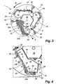
Fig 2 is a three-dimensional view and shows the rotor offig 1 with the upper disc removed. -
Fig 3 shows the view offig 2 as seen from above in a two dimensional perspective. -
Fig 4 is an enlarged view of a wear plate shown infigure 3 . -
Fig 5 is a cross section along the line V-V offig 4 and shows a holding pin holding the wear plate, according a first embodiment of the invention. -
Fig 6 is three dimensional view of the holding pin shown infig 5 . -
Fig 7 shows a part of a wall segment as seen from the inside, i.e. in the direction of arrow VII infig 3 , of the rotor. -
Fig 8 is a cross section along the line VIII infig 7 . -
Fig 9 is an enlarged view showing the wear plate offig 3 as seen in the direction of arrow IX infig 4 . -
Fig 10 is a section view and shows a holding pin according to a second embodiment of the invention. -
Fig 11 is a cross section and shows a wedge according to a third embodiment of the invention. -
Fig 12 is a three dimensional view and shows the wedge offig 11 upside down and in detail. -
Fig 13 is a cross section and shows the principles of mounting and dismounting the wedge shown infig 11 and 12 . -
Fig 14 is a cross section and shows a wedge according to a fourth embodiment of the invention. -
Fig 1 shows arotor 1 for use in a VSI-crusher. Therotor 1 has a roof in the form of anupper disc 2 having atop wear plate 3 and a floor in the form of alower disc 4. Thelower disc 4 has ahub 6, which is welded to thedisc 4. Thehub 6 is to be connected to a shaft (not shown) for rotating therotor 1 inside the housing of a VSI-crusher. - The
upper disc 2 has acentral opening 8 through which material to be crushed can be fed into therotor 1. Theupper disc 2 is protected from wear byupper wear plates upper disc 2 is protected from rocks impacting therotor 1 from above by thetop wear plate 3. As is better shown infig 2 thelower disc 4 is protected from wear by threelower wear plates - The upper and
lower discs wall segments wall segments outflow openings - At each
outflow opening respective wall segment wear tips respective wall segment - A
distributor plate 38 is fastened to the centre of thelower disc 4. Thedistributor plate 38 distributes the material that is fed via theopening 8 in theupper disc 2 and protects thelower disc 4 from wear and impact damages caused by the material fed via theopening 8. - During operation of the rotor 1 a
bed 40 of material is built up inside therotor 1 against each of the threewall segments fig 3 only thebed 40 located adjacent to thewall segment 20 is shown. Thebed 40, which consists of material that has been fed to therotor 1 and then has been trapped inside it, extends from arear support plate 42 to thewear tips bed 40 protects thewall segment 20 and thewear tips rotor 1 via thecentral opening 8 and ejected via theoutflow opening 26. The arrow R indicates the rotational direction of therotor 1 during operation of the VSI-crusher. - Each
wall segment cavity wear plate cavity wear plates rotor 1 and in particular thewear tips rotor 1. - The
wall segment 20 comprises afirst wall portion 20a which is substantially tangential to thedisc 4 and thus therotor 1. Asecond wall portion 20b is fixed to thefirst portion 20a such that an "L" with an angle of about 130° is formed of the twoportions -
Fig 4 shows atip holder 50 holding thewear tip 36 and extending along thefirst wall portion 20a. As can be seen fromfig 4 thewear plate 14 has afirst face 52 being located adjacent to and in contact with the inner side of thesecond wall portion 20b. Thewear plate 14 has asecond face 54 being located adjacent to and for a part of its length in contact with inner side of thefirst wall portion 20a. Athird face 56 of the wear plate is located adjacent to, but not in contact with, thedistributor plate 38 for a part of its length. Afourth face 58 is located adjacent to theoutflow opening 26. - The
wear plate 14 is flat an may be made from white iron thus being resistant to both abrasion and impact forces. As alternative thewear plate 14 may be made by coating a hard metal, such as tungsten carbide, or a ceramic on a flat steel base. The flat shape is preferable since it makes the wear plate cheap to manufacture and easy to install. The flat shape also promotes the stability of thebed 40 of material since no protrusions on the surface of the wear plate disturb thebed 40. - The
wear plate 14 is kept in place at four positions. Two holding members in the form of retractable holding pins 60, 62 are inserted through holes in thesecond wall portion 20b. Agusset 64 is located adjacent to thefourth face 58. Ashoulder 66 of thetip holder 50 holds thewear plate 14 in position at thefirst wall portion 20a. - In
fig 5 the holdingpin 60 is shown holding thewear plate 14 in position. The holdingpin 60 has the shape of a "T" and thus has a holding part or astem 68 and a handle member in the form of atop part 70. Thestem 68 is inserted through ahole 72 in thesecond wall portion 20b. At an inner side of thewall portion 20b thestem 68 is in contact with theupper surface 74 of thewear plate 14. Thewear plate 14 rests in direct contact with a first side of thewall portion 20b said first side being theinner wall surface 76 of thesecond wall portion 20b. When therotor 1 is rotated the centrifugal forces will drive thewear plate 14 into firm contact with theinner wall surface 76 such that there is no gap between thefirst face 52 of thewear plate 14 and theinner wall surface 76. Thus there is no risk that rock material could cause wear at thesensitive transition 78 between thesecond wall portion 20b and thedisc 4. Thewear plate 14 is bevelled at the under side so that any welding joint joining thesecond wall portion 20b and thelower disc 4 does not prevent thewear plate 14 from contacting thesecond wall portion 20b. - An "L"-shaped
bracket 80 is welded to a second side of saidwall portion 20b, said second side being theouter wall surface 82 of thewall portion 20b and opposite to theinner wall surface 76 thereof. Thebracket 80 has ahole 84 in its vertical portion, thehole 84 being in register with thehole 72 in thesecond wall portion 20b. The holdingpin 60 is inserted such that thestem 68 passes through thehole 84 of thebracket 80 and then through thehole 72 in thesecond wall portion 20b. Thestem 68 bears against theupper surface 74 of thewear plate 14. Aspring dowel pin 86 is inserted through ahole 88 in thestem 68. Thespring dowel pin 86 is located between theouter wall surface 82 of thesecond wall portion 20b and the vertical portion of thebracket 80 such that the holdingpin 60 cannot move in any direction. - In
fig 6 thepin 60 is shown retracted and with thespring dowel pin 86 inserted in thehole 88 in thestem 68. Thestem 68 is preferably manufactured from mild steel since it is protected from wear by thebed 40 of material. During normal operation of therotor 1 thestem 68 may be worn slightly at its free end since the extension of thebed 40 to a certain degree is alternately reduced and expanded also during normal operation. Thestem 68 preferably has such a length that it is entirely covered by thebed 40 of material. The round shape of thestem 68 is easy to manufacture, fits well to abored hole 72 and makes the holding properties of thestem 68 independent of any turning of the holdingpin 60. Thetop part 70 is shaped so as to make insertion and withdrawal of the holdingpin 60 easy. The material of thetop part 70 is preferably mild steel. - In
fig 7 threetip holders 50 are shown. Eachtip holder 50 comprises a holdingpart 92 that holds therespective wear tip wear tips lower disc 4 to the upper disc 2 (theupper disc 2 being outside the view offig 7 ). Attached to the holdingpart 92 of eachtip holder 50 is a holdingplate 94. The holdingplate 94 has a threadedbar 96 which extends through ahole 98 in thesecond wall portion 20b. A not shown nut is fixed to the threadedbar 96 at the other side of thesecond wall portion 20b thus securing therespective tip holders 50 to thewall segment 20. The vertical extension of the holdingplate 94 is smaller than that of the holdingpart 92. Anlower shoulder 66 and anupper shoulder 100 is thus formed on the holdingplate 94. Thelower shoulder 66 of thetip holder 50 holding thewear tip 32 in place holds thewear plate 14 in position. The upper shoulder (not shown infigure 7 ) of thetip holder 50 holding thewear tip 36 holds an upper wear plate in position in a similar manner. - In
fig 8 the principle of theshoulder 66 is shown in more detail. As can be seen thewear plate 14 extends under theshoulder 66 of thetip holder 50 such that thesecond face 54 of thewear plate 14 is in direct and close contact with thefirst wall portion 20a. Thus it is ensured that thesensitive transition 102 between thefirst wall portion 20a and thelower disc 4 is protected by thewear plate 14. Thewear plate 14 is bevelled at the under side so that any welding joint joining thefirst wall portion 20a and thelower disc 4 does not prevent thewear plate 14 from contacting thefirst wall portion 20a. During operation the centrifugal force generated by the rotation of therotor 1 will force the wear plate outwards such that a direct contact between thefirst face 52 of thewear plate 14 and thesecond wall portion 20b and between thesecond face 54 of thewear plate 14 and thefirst wall portion 20a is ensured. Thus the risk of wear atsensitive transitions wear plate 14 in relation to thewall segment 20 ensures that therotor 1 is kept well balanced. - In
fig 9 the holding of thewear plate 14 at theoutflow opening 26 is shown in detail. Thegusset 64 has anotch 104 adjacent to thelower disc 4. Thewear plate 14 has, at itsfourth face 58, alip 106. Thelip 106 fits under thenotch 104 such that thewear plate 14 is held in position under thegusset 64. Thegusset 64 has a shorter height from theplate 4 than thewear plate 14 to protect thegusset 64 from wear caused by the material leaving theoutflow opening 26. - When mounting a
wear plate 14 thewear plate 14 is first put on thelower disc 4 such that thewear plate 14 is in contact with therear support plate 42. Thewear plate 14 is then guided against theoutflow opening 26 such that thelip 106 engages thenotch 104 of thegusset 64. The holding pins 60, 62 are inserted via the holes in thesecond wall portion 20b and are then locked with the help of the spring dowel pins 86. The centrifugal force will then force thewear plate 14 into firm, direct' contact with the first andsecond wall portions wear plate 14 is basically performing the steps above in the reverse order. - It will be appreciated that, although the description above is directed to wear
plates lower disc 4 of therotor 1, the principles described above of holding wear plates in position are applied also for the holding of theupper wear plates upper disc 2. -
Fig 10 shows a holdingpin 160 according to a second embodiment of the invention. This embodiment differs from the holdingpin 60 described infig 5 and 6 mainly in that acircular stem 168 of the holdingpin 160 extends into a horizontal, circularwear plate hole 115 formed in afirst face 152 of awear plate 114. Thus thestem 168 is well protected from wear, also during the time before abed 40 of material has been built up against thewall segment 20. A handle in the form of atop part 170 is used for inserting thestem 168 of the holdingpin 160 into thewear plate hole 115 when mounting thewear plate 114 to therotor 1. As can be seen thefirst face 152 of thewear plate 114 rests in direct contact with theinner wall surface 76 of thesecond wall portion 20b. -
Fig 11 shows a holding member in the form of a bar shaped as awedge 260 according to a third embodiment of the invention. Thewedge 260 holds thewear plate 14 in position. Thewedge 260 is inserted through ahole 272 in thesecond wall portion 20b. At an inner side of thewall portion 20b thewedge 260 is in contact with theupper surface 74 of thewear plate 14. Thewear plate 14 rests in direct contact with a first side of thewall portion 20b said first side being theinner wall surface 76 of thesecond wall portion 20b. When therotor 1 is rotated the centrifugal forces will drive thewear plate 14 into firm contact with theinner wall surface 76 in a similar manner as described above with reference tofig 5 . - A
spring dowel pin 286 or aring cotter 287 is mounted on thewedge 260 at a second side of saidwall portion 20b, said second side being theouter wall surface 82 of thewall portion 20b and opposite to theinner wall surface 76 thereof (fig 11 andfig 13 show both aspring dowel pin 286 and aring cotter 287, however it will be appreciated that only one of thepin 286 and thecotter 287 is required). The spring dowel pin 286 (or the ring cotter 287) prevents thewedge 260 from falling out of thehole 272 in the event thewedge 260 would accidentally become released from thehole 272. -
Fig 12 shows thewedge 260 turned upside down and in greater detail. The lower long side of thewedge 260 is aflat side 262 intended for contacting theupper surface 74 of thewear plate 14. At thelarger end 264 of the wedge 260 a vertical mountingsurface 266 is formed. At thesmaller end 268 of the wedge 260 avertical dismounting surface 270 is formed. Thewedge 260 has three throughholes smaller end 268. The three throughholes spring dowel pin 286 or aring cotter 287 in a suitable position. The upper long side of thewedge 260 is abevelled surface 278 intended for contacting the upper part of thehole 272 and to lock thewedge 260 to thesecond wall portion 20b. - The mounting and dismounting of the
wedge 260 will now be described with reference tofig 13 . When mounting thewear plate 14 and thewedge 260 there is nobed 40 of material present. Thewear plate 14 is placed on thelower disc 4 such that thefirst face 52 of thewear plate 14 rests in close contact with the inner wall face 76 of thesecond wall portion 20b. Thesmaller end 268 of thewedge 260 is guided through thehole 272 from the inner side of thesecond wall portion 20b. A hammer or similar tool is used to strike the mountingsurface 266 in the direction of the arrow M. The stroke results in that theflat side 262 and thebevelled surface 278 of thewedge 260 locks against theupper surface 74 of thewear plate 14 and the upper part of thehole 272 respectively. Finally the spring dowel pin 286 (or the ring cotter 287) is inserted into one of theholes fig 12 ) such that thewedge 260 cannot accidentally fall out of thehole 272. - During operation of the crusher a
bed 40 of material will build up against the inner wall face 76 of thesecond wall portion 20b and on thewear plate 14. Thebed 40 will thus cover thelarger end 264 of thewedge 260 as illustrated infig 13 . Thus thewedge 260 is protected from wear during operation. The rotation of therotor 1 will cause a centrifugal force. The centrifugal force will tend to push thewedge 260 towards the periphery of therotor 1 and thus further into thehole 272. The centrifugal force in combination with thebed 40 built up around thelarger end 264 of thewedge 260 ensures that there is a minimum risk that thewedge 260 would fall out of position during crusher operation. The spring dowel pin 286 (or the ring cotter 287) merely serves to ensure that thewedge 260 stays in place during the maintenance stop and at the start of the crusher. - When the
wear plate 14 is to be removed the following procedure is used. The spring dowel pin 286 (or the ring cotter 287) is removed. A hammer or similar tool is used to strike the dismountingsurface 270 in the direction of the arrow D. The stroke results in that theflat side 262 and thebevelled surface 278 of thewedge 260 release from thesurface 74 of thewear plate 14 and the upper part of thehole 272 respectively. Simultaneously the mountingsurface 266 will be forced into thebed 40 of material and break thebed 40 into pieces. Thus thebed 40 will become easier to remove from the rotor. Finally thewedge 260 is taken out of thehole 272 and thewear plate 14 can be removed. -
Fig 14 shows a holding member in the form of a bar shaped as awedge 360 according to a fourth embodiment of the invention. Thewedge 360 is made of a polymer material, preferably a rather hard polymer material such as polyamide plastic (often referred to as nylon), and has a similar shape as thewedge 260 shown inFigs. 11 to 13 . Thewedge 360 however has no through holes and no spring dowel pin or cotter ring is required to ensure that thewedge 360 is kept in place. Thewedge 360 is inserted through thehole 272 in thesecond wall portion 20b. At an inner side of thewall portion 20b thewedge 360 is in contact with theupper surface 74 of thewear plate 14. Thewear plate 14 rests in direct contact with the inner wall face 76 of thesecond wall portion 20b in the same way as described above with reference toFig 13 . - The lower long side of the
wedge 360 is aflat side 362 intended for contacting theupper surface 74 of thewear plate 14. At thelarger end 364 of the wedge 360 a vertical mountingsurface 366 is formed. At thesmaller end 368 of the wedge 360 avertical dismounting surface 370 is formed. The upper long side of thewedge 360 is aflat surface 378, which is similar to thesurface 278 shown inFig. 12 but is not bevelled. Theflat surface 378 is intended for contacting the upper part of thehole 272 and to lock thewedge 360 to thesecond wall portion 20b. Asupport 386 is fixed to thelower disc 4 adjacent to theouter wall surface 82 of thewall portion 20b. Thesupport 386 supports that part of theflat side 362 of thewedge 360 that extends out of thehole 272. Thus thesupport 386 ensures that thewedge 360 is kept in proper position by keeping theflat side 362 in a horizontal position. - When mounting the
wear plate 14 and thewedge 360 there is nobed 40 of material present. Thewear plate 14 is placed on thelower disc 4 in a similar way as described above and asmaller end 368 of thewedge 360 is guided through thehole 272 from the inner side of thesecond wall portion 20b. A hammer or similar tool is used to strike the mountingsurface 366 in the direction of the arrow M. The stroke results in that theflat side 362 and thesurface 378 of thewedge 360 locks against theupper surface 74 of thewear plate 14 and the upper part of thehole 272 respectively. Since thewedge 360 is made of a polymer material, which is softer than the material, such as steel, of which thewall portion 20b is made, the stroke will cause thesurface 378 to be irreversibly deformed by the upper part of thehole 272 without causing any damage to thehole 272. The deformation of thesurface 378 will form a press fit providing a very secure attachment of thewedge 360 in thehole 272 and no spring dowel pin or cotter pin is required. - During operation of the crusher a
bed 40 of material will build up against the inner wall face 76 of thesecond wall portion 20b and on thewear plate 14. Thebed 40 will thus cover thelarger end 364 of thewedge 360 and protect it from wear in a similar way as described above with reference toFig 13 . The deformation of thewedge 360 caused by the stroke in combination with the fact that thebed 40 covers thelarger end 364 of thewedge 360 minimizes the risk that thewedge 360 could fall out of position during operation. If thewedge 360, in spite of this, would accidentally fall out of position, the fact that thewedge 360 is made of a polymer material minimizes the risk that any mechanical damage could be caused to therotor 1 and avoids any metal contamination of the crushed product.
The procedure used for removing thewedge 360 is similar to the removal procedure described above with reference toFig. 13 . The main difference is that no spring dowel pin or cotter ring needs to be removed before striking the dismountingsurface 370 in the direction of the arrow D with a hammer or similar tool. - It will be appreciated that numerous modifications of the embodiments described above are possible within the scope of the appended claims.
- According to another embodiment the holding
pin 60 is replaced with a bolt inserted through thesecond wall portion 20b and being fixed at the outer side of thesecond wall portion 20b. This fixing could be achieved by a nut welded to the hole at the outside of thesecond wall portion 20b. Thus the nut would replace thebracket 80, the hole of the nut being in register with thehole 72 in thesecond wall portion 20b. The threaded part of the bolt extends through the hole in thesecond wall portion 20b such that it holds thewear plate 14 in place at the inside of thesecond wall portion 20b in a similar manner as described above regarding thestem 68. To decrease the problem of bed material clogging the thread of the bolt it is preferable to turn down the thread of the bolt at the part of the bolt that is intended for being located inside the bed. In such a case the bolt is threaded only at the part being intended for location inside the nut welded to the outside of thesecond wall portion 20b. A further possibility is to provide the thread inside the actual hole in the second wall portion. In such a case no nut would be needed. - According to another embodiment the
stem 68 is shaped to have a tight fit to thehole 72 in thesecond wall portion 20b. Thus no bracket or spring dowel pin is needed. The fixing of thepin 60 is achieved by the interference fit of thestem 68 in thehole 72. - The main purpose of the top part is to make insertion and removal of the
pin 60 easy. As alternative to the cylindricaltop part 70 shown infig 6 the top part may as alternative be shaped as a normal handle or in any other shape that is convenient for easy insertion and removal of the pin. - As alternative to the spring dowel pin 86 a split pin or any other type of key could be used to lock the holding pins 60, 62 in their respective positions. It is also possible to use a locking screw to lock the holding
pin 60. - As shown above in
fig 5 thestem 68 is in close contact with the upper surface of thewear plate 14. It is, however, also possible to let thestem 68 extend into awear plate 114 through ahorizontal hole 115 formed at thefirst face 152 of thewear plate 114 as shown infig 10 . Still another possibility is to provide a thread on the stem and also inside the hole in the wear plate such that the wear plate may be screwed against the second wall portion. - A holding
pin 60 as described above may also be used for holding thewear plate 14 in position also at thefirst wall portion 20a, the holdingpin 60 thus replacing or assisting theshoulder 66 of thetip holder 50 in holding thewear plate 14 in position at thefirst wall portion 20a.
Claims (15)
- A vertical shaft impact crusher having a rotor (1) and a holding member (60, 62; 160; 260; 360) adapted to hold a horizontal wear plate (14; 114) in position on the rotor (1)
characterised in that the holding member (60, 62; 160; 260; 360) further comprises a holding part (68; 168; 262) which is adapted to hold the wear plate (14; 114) in position and a fixing means (86, 88; 278) which releasably fixes the holding member (60, 62; 160; 260; 360) to a vertical wall segment (20) of said rotor (1) such that the wear plate (14; 114) bears against a first surface (76) of said vertical wall segment (20). - A crusher according to claim 1, wherein the holding part comprises a bar (68; 168; 260) adapted to extend through a hole (72; 272) in the wall segment (20).
- A crusher according to claim 2, wherein said fixing means comprises a surface portion (278) of said bar (68; 260), the surface portion (278) being adapted to interact with the hole (72; 272) in the wall segment (20) for forming an interference fit of the bar (68, 260) in the hole.
- A crusher according to claim 2, wherein the fixing means (86, 88) is adapted to be located at a second surface (82) of said wall segment (20) opposite to said first surface (76) thereof.
- A crusher according to claim 4, wherein said fixing means comprises a pin (86) and a pin hole (88), said pin hole (88) being adapted to receive said pin (86) for fixing the holding member (60, 62).
- A crusher according to claim 5, wherein the fixing means further comprises a bracket (80) to be mounted on the wall segment (20) at said second surface (82) thereof, the pin hole (88) being adapted to be located between a vertical portion of said bracket (80) and said second surface (82) of said wall segment (20) such that the pin (86) may be inserted in the pin hole (88) between said vertical portion and said wall segment (20).
- A crusher according to any one of claims 4 to 6, wherein the holding member comprises a handle member (70) for inserting the holding part (68) through said hole (72) in the wall segment (20) from said second surface (82) of said wall segment (20).
- A crusher according to claim 2, wherein said fixing means comprises a surface portion of said bar, the surface portion being threaded to interact with a threaded portion of said hole in the wall segment.
- A crusher according to any one of the preceding claims, the holding part (68; 262) being adapted to interact with a surface (74) of said wear plate (14), said surface (74) being the surface of the wear plate (14) that is remote from a rotor surface (4) to be protected by said wear plate (14).
- A crusher according to any one of claims 1-8, the holding part (168) being adapted to be inserted into a wear plate hole (115) formed in said wear plate (114).
- A crusher according to any one of claims 1-3 and 9, wherein the holding member comprises a wedge (260), the wedge (260) being adapted to be inserted into a hole (272) of the vertical wall segment (20) and to be locked therein.
- A crusher according to claim 11, wherein the wedge (260) is adapted to be inserted into the hole (272) from the inner side of said vertical wall segment (20) such that the larger end (264) of the wedge (260) will become covered by a bed (40) of material during crusher operation.
- A crusher according to claim 12, wherein the wedge (260) comprises a dismounting surface (270) adapted for dismounting the wedge (260) by a stroke impacting the dismounting surface (270), the dismounting surface (270) being adapted to be located at the outer side of said vertical wall segment (20) such that the dismounting surface (270) will remain free of any bed (40) of material during crusher operation.
- A crusher according to claim 13, wherein the wedge comprises a surface (266) adapted for being covered by the bed (40) of material during crusher operation and for breaking the bed (40) of material when a stroke is made to the dismounting surface (270).
- A crusher according to any one of claims 11 to 14, wherein the wedge (360) is made of polymer material.
Applications Claiming Priority (3)
| Application Number | Priority Date | Filing Date | Title |
|---|---|---|---|
| SE0202534A SE523549C2 (en) | 2002-08-28 | 2002-08-28 | Part for holding a wear part in a crusher |
| SE0202534 | 2002-08-28 | ||
| PCT/SE2003/001319 WO2004020102A1 (en) | 2002-08-28 | 2003-08-27 | A member for holding a wear part of a crusher |
Publications (2)
| Publication Number | Publication Date |
|---|---|
| EP1545782A1 EP1545782A1 (en) | 2005-06-29 |
| EP1545782B1 true EP1545782B1 (en) | 2009-08-12 |
Family
ID=20288815
Family Applications (1)
| Application Number | Title | Priority Date | Filing Date |
|---|---|---|---|
| EP03791521A Expired - Lifetime EP1545782B1 (en) | 2002-08-28 | 2003-08-27 | A member for holding a wear part of a crusher |
Country Status (9)
| Country | Link |
|---|---|
| US (1) | US7300009B2 (en) |
| EP (1) | EP1545782B1 (en) |
| AT (1) | ATE439190T1 (en) |
| AU (1) | AU2003293131A1 (en) |
| CA (1) | CA2494862C (en) |
| DE (1) | DE60328800D1 (en) |
| EA (1) | EA006360B1 (en) |
| SE (1) | SE523549C2 (en) |
| WO (1) | WO2004020102A1 (en) |
Families Citing this family (7)
| Publication number | Priority date | Publication date | Assignee | Title |
|---|---|---|---|---|
| SE523598C3 (en) * | 2002-08-28 | 2004-06-09 | Sandvik Ab | Holder for a wear part in a crusher |
| US7669621B2 (en) * | 2006-08-14 | 2010-03-02 | Cem Machine, Inc. | Stationary bedknife for disc chipper apparatus |
| US8051887B2 (en) * | 2009-11-04 | 2011-11-08 | Cem Machine, Inc. | Primary and counter knife assembly for use in wood chipper |
| WO2011128854A2 (en) * | 2010-04-14 | 2011-10-20 | Eriogenix (Pty) Ltd | Vertical shaft impact crushers |
| WO2013140047A1 (en) * | 2012-03-23 | 2013-09-26 | Metso Minerals, Inc. | Improvements in a rotor for a rock crusher |
| DE112017003304T5 (en) | 2016-06-29 | 2019-03-14 | Superior Industries, Inc. | Impact crusher with vertical shaft |
| US10967380B2 (en) * | 2017-03-31 | 2021-04-06 | Stanley Black & Decker, Inc. | Heavy duty material processor |
Family Cites Families (8)
| Publication number | Priority date | Publication date | Assignee | Title |
|---|---|---|---|---|
| US3154259A (en) | 1961-12-26 | 1964-10-27 | Simplicity Eng Co | Crusher mechanism |
| US4796822A (en) | 1983-11-18 | 1989-01-10 | Acrowood Corporation | Impeller for an impact crusher |
| US4659026A (en) * | 1984-06-27 | 1987-04-21 | Rexnord Inc. | Guard rings for vertical shaft impact crusher |
| US4896838A (en) * | 1988-10-31 | 1990-01-30 | Cedarapids, Inc. | Rotor for vertical shaft impact crushers |
| US5029761A (en) * | 1989-11-30 | 1991-07-09 | Nordberg Inc. | Liner wear insert for vertical shaft impactor rotor |
| US4997368A (en) * | 1990-03-12 | 1991-03-05 | Mayer Norman M | Oral measuring device |
| EP1014882B1 (en) * | 1997-08-27 | 2008-10-29 | John E. Garrison | Improved dental wedge for utilization in dental restoration |
| US20030232661A1 (en) * | 2002-06-18 | 2003-12-18 | Greer Jesse A. | Golf club putter head |
-
2002
- 2002-08-28 SE SE0202534A patent/SE523549C2/en not_active IP Right Cessation
-
2003
- 2003-08-27 EA EA200500414A patent/EA006360B1/en not_active IP Right Cessation
- 2003-08-27 DE DE60328800T patent/DE60328800D1/en not_active Expired - Lifetime
- 2003-08-27 AU AU2003293131A patent/AU2003293131A1/en not_active Abandoned
- 2003-08-27 EP EP03791521A patent/EP1545782B1/en not_active Expired - Lifetime
- 2003-08-27 WO PCT/SE2003/001319 patent/WO2004020102A1/en not_active Application Discontinuation
- 2003-08-27 CA CA2494862A patent/CA2494862C/en not_active Expired - Fee Related
- 2003-08-27 AT AT03791521T patent/ATE439190T1/en not_active IP Right Cessation
- 2003-08-27 US US10/525,976 patent/US7300009B2/en not_active Expired - Lifetime
Also Published As
| Publication number | Publication date |
|---|---|
| SE523549C2 (en) | 2004-04-27 |
| CA2494862A1 (en) | 2004-03-11 |
| AU2003293131A1 (en) | 2004-03-19 |
| WO2004020102A1 (en) | 2004-03-11 |
| SE0202534D0 (en) | 2002-08-28 |
| DE60328800D1 (en) | 2009-09-24 |
| EA200500414A1 (en) | 2005-08-25 |
| EP1545782A1 (en) | 2005-06-29 |
| EA006360B1 (en) | 2005-12-29 |
| ATE439190T1 (en) | 2009-08-15 |
| US20050269437A1 (en) | 2005-12-08 |
| CA2494862C (en) | 2011-06-21 |
| SE0202534L (en) | 2004-02-29 |
| US7300009B2 (en) | 2007-11-27 |
Similar Documents
| Publication | Publication Date | Title |
|---|---|---|
| JP2910854B2 (en) | Tip holder for mineral crusher | |
| CA1131189A (en) | Shell liner assembly for ore grinding mills | |
| EP2160244B1 (en) | Distributor plate for a vsi-crusher and a method of replacing such a plate | |
| US7677484B2 (en) | Wear part for a crusher | |
| US7607601B2 (en) | Wear tip for rotary mineral breaker | |
| EP1545782B1 (en) | A member for holding a wear part of a crusher | |
| US7257876B2 (en) | Holder for a wear part of a crusher | |
| EP2470304B1 (en) | Distributor plate locking mechanism for a vertical shaft impact crusher | |
| EP2532429A1 (en) | Holding arrangement for a rim liner of a crusher | |
| US3995782A (en) | Pulverizing device | |
| US7530512B2 (en) | Rotor for a crusher | |
| EP2572792B1 (en) | Wear tip holder for VSI crusher, and method of reducing wear of VSI crusher rotor | |
| AU2021106978A4 (en) | A Wear System | |
| GB2248410A (en) | Tip holder for mineral breaker | |
| WO2023023766A1 (en) | A wear system | |
| NZ238349A (en) | Tip holder for rotor of centrifugal mineral breaker with abrasion resistant inserts |
Legal Events
| Date | Code | Title | Description |
|---|---|---|---|
| PUAI | Public reference made under article 153(3) epc to a published international application that has entered the european phase |
Free format text: ORIGINAL CODE: 0009012 |
|
| 17P | Request for examination filed |
Effective date: 20050224 |
|
| AK | Designated contracting states |
Kind code of ref document: A1 Designated state(s): AT BE BG CH CY CZ DE DK EE ES FI FR GB GR HU IE IT LI LU MC NL PT RO SE SI SK TR |
|
| AX | Request for extension of the european patent |
Extension state: AL LT LV MK |
|
| RAP1 | Party data changed (applicant data changed or rights of an application transferred) |
Owner name: SANDVIK INTELLECTUAL PROPERTY AB |
|
| DAX | Request for extension of the european patent (deleted) | ||
| GRAP | Despatch of communication of intention to grant a patent |
Free format text: ORIGINAL CODE: EPIDOSNIGR1 |
|
| GRAS | Grant fee paid |
Free format text: ORIGINAL CODE: EPIDOSNIGR3 |
|
| GRAA | (expected) grant |
Free format text: ORIGINAL CODE: 0009210 |
|
| AK | Designated contracting states |
Kind code of ref document: B1 Designated state(s): AT BE BG CH CY CZ DE DK EE ES FI FR GB GR HU IE IT LI LU MC NL PT RO SE SI SK TR |
|
| REG | Reference to a national code |
Ref country code: GB Ref legal event code: FG4D |
|
| REG | Reference to a national code |
Ref country code: CH Ref legal event code: EP |
|
| REG | Reference to a national code |
Ref country code: IE Ref legal event code: FG4D |
|
| REF | Corresponds to: |
Ref document number: 60328800 Country of ref document: DE Date of ref document: 20090924 Kind code of ref document: P |
|
| PG25 | Lapsed in a contracting state [announced via postgrant information from national office to epo] |
Ref country code: ES Free format text: LAPSE BECAUSE OF FAILURE TO SUBMIT A TRANSLATION OF THE DESCRIPTION OR TO PAY THE FEE WITHIN THE PRESCRIBED TIME-LIMIT Effective date: 20091123 Ref country code: SE Free format text: LAPSE BECAUSE OF FAILURE TO SUBMIT A TRANSLATION OF THE DESCRIPTION OR TO PAY THE FEE WITHIN THE PRESCRIBED TIME-LIMIT Effective date: 20090812 Ref country code: AT Free format text: LAPSE BECAUSE OF FAILURE TO SUBMIT A TRANSLATION OF THE DESCRIPTION OR TO PAY THE FEE WITHIN THE PRESCRIBED TIME-LIMIT Effective date: 20090812 |
|
| NLV1 | Nl: lapsed or annulled due to failure to fulfill the requirements of art. 29p and 29m of the patents act | ||
| PG25 | Lapsed in a contracting state [announced via postgrant information from national office to epo] |
Ref country code: SI Free format text: LAPSE BECAUSE OF FAILURE TO SUBMIT A TRANSLATION OF THE DESCRIPTION OR TO PAY THE FEE WITHIN THE PRESCRIBED TIME-LIMIT Effective date: 20090812 Ref country code: NL Free format text: LAPSE BECAUSE OF FAILURE TO SUBMIT A TRANSLATION OF THE DESCRIPTION OR TO PAY THE FEE WITHIN THE PRESCRIBED TIME-LIMIT Effective date: 20090812 |
|
| PG25 | Lapsed in a contracting state [announced via postgrant information from national office to epo] |
Ref country code: MC Free format text: LAPSE BECAUSE OF NON-PAYMENT OF DUE FEES Effective date: 20090831 Ref country code: PT Free format text: LAPSE BECAUSE OF FAILURE TO SUBMIT A TRANSLATION OF THE DESCRIPTION OR TO PAY THE FEE WITHIN THE PRESCRIBED TIME-LIMIT Effective date: 20091212 Ref country code: BG Free format text: LAPSE BECAUSE OF FAILURE TO SUBMIT A TRANSLATION OF THE DESCRIPTION OR TO PAY THE FEE WITHIN THE PRESCRIBED TIME-LIMIT Effective date: 20091112 |
|
| REG | Reference to a national code |
Ref country code: CH Ref legal event code: PL |
|
| PG25 | Lapsed in a contracting state [announced via postgrant information from national office to epo] |
Ref country code: EE Free format text: LAPSE BECAUSE OF FAILURE TO SUBMIT A TRANSLATION OF THE DESCRIPTION OR TO PAY THE FEE WITHIN THE PRESCRIBED TIME-LIMIT Effective date: 20090812 Ref country code: LI Free format text: LAPSE BECAUSE OF NON-PAYMENT OF DUE FEES Effective date: 20090831 Ref country code: RO Free format text: LAPSE BECAUSE OF FAILURE TO SUBMIT A TRANSLATION OF THE DESCRIPTION OR TO PAY THE FEE WITHIN THE PRESCRIBED TIME-LIMIT Effective date: 20090812 Ref country code: CH Free format text: LAPSE BECAUSE OF NON-PAYMENT OF DUE FEES Effective date: 20090831 Ref country code: CZ Free format text: LAPSE BECAUSE OF FAILURE TO SUBMIT A TRANSLATION OF THE DESCRIPTION OR TO PAY THE FEE WITHIN THE PRESCRIBED TIME-LIMIT Effective date: 20090812 Ref country code: DK Free format text: LAPSE BECAUSE OF FAILURE TO SUBMIT A TRANSLATION OF THE DESCRIPTION OR TO PAY THE FEE WITHIN THE PRESCRIBED TIME-LIMIT Effective date: 20090812 |
|
| PG25 | Lapsed in a contracting state [announced via postgrant information from national office to epo] |
Ref country code: SK Free format text: LAPSE BECAUSE OF FAILURE TO SUBMIT A TRANSLATION OF THE DESCRIPTION OR TO PAY THE FEE WITHIN THE PRESCRIBED TIME-LIMIT Effective date: 20090812 |
|
| PLBE | No opposition filed within time limit |
Free format text: ORIGINAL CODE: 0009261 |
|
| STAA | Information on the status of an ep patent application or granted ep patent |
Free format text: STATUS: NO OPPOSITION FILED WITHIN TIME LIMIT |
|
| PG25 | Lapsed in a contracting state [announced via postgrant information from national office to epo] |
Ref country code: BE Free format text: LAPSE BECAUSE OF FAILURE TO SUBMIT A TRANSLATION OF THE DESCRIPTION OR TO PAY THE FEE WITHIN THE PRESCRIBED TIME-LIMIT Effective date: 20090812 |
|
| 26N | No opposition filed |
Effective date: 20100517 |
|
| PG25 | Lapsed in a contracting state [announced via postgrant information from national office to epo] |
Ref country code: IE Free format text: LAPSE BECAUSE OF NON-PAYMENT OF DUE FEES Effective date: 20090827 |
|
| PG25 | Lapsed in a contracting state [announced via postgrant information from national office to epo] |
Ref country code: GR Free format text: LAPSE BECAUSE OF FAILURE TO SUBMIT A TRANSLATION OF THE DESCRIPTION OR TO PAY THE FEE WITHIN THE PRESCRIBED TIME-LIMIT Effective date: 20091113 |
|
| PG25 | Lapsed in a contracting state [announced via postgrant information from national office to epo] |
Ref country code: IT Free format text: LAPSE BECAUSE OF FAILURE TO SUBMIT A TRANSLATION OF THE DESCRIPTION OR TO PAY THE FEE WITHIN THE PRESCRIBED TIME-LIMIT Effective date: 20090812 |
|
| PG25 | Lapsed in a contracting state [announced via postgrant information from national office to epo] |
Ref country code: LU Free format text: LAPSE BECAUSE OF NON-PAYMENT OF DUE FEES Effective date: 20090827 |
|
| PG25 | Lapsed in a contracting state [announced via postgrant information from national office to epo] |
Ref country code: HU Free format text: LAPSE BECAUSE OF FAILURE TO SUBMIT A TRANSLATION OF THE DESCRIPTION OR TO PAY THE FEE WITHIN THE PRESCRIBED TIME-LIMIT Effective date: 20100213 |
|
| PG25 | Lapsed in a contracting state [announced via postgrant information from national office to epo] |
Ref country code: CY Free format text: LAPSE BECAUSE OF FAILURE TO SUBMIT A TRANSLATION OF THE DESCRIPTION OR TO PAY THE FEE WITHIN THE PRESCRIBED TIME-LIMIT Effective date: 20090812 |
|
| REG | Reference to a national code |
Ref country code: FR Ref legal event code: PLFP Year of fee payment: 14 |
|
| PGFP | Annual fee paid to national office [announced via postgrant information from national office to epo] |
Ref country code: FI Payment date: 20160809 Year of fee payment: 14 |
|
| PGFP | Annual fee paid to national office [announced via postgrant information from national office to epo] |
Ref country code: FR Payment date: 20160712 Year of fee payment: 14 |
|
| PG25 | Lapsed in a contracting state [announced via postgrant information from national office to epo] |
Ref country code: FI Free format text: LAPSE BECAUSE OF NON-PAYMENT OF DUE FEES Effective date: 20170827 |
|
| REG | Reference to a national code |
Ref country code: FR Ref legal event code: ST Effective date: 20180430 |
|
| PG25 | Lapsed in a contracting state [announced via postgrant information from national office to epo] |
Ref country code: FR Free format text: LAPSE BECAUSE OF NON-PAYMENT OF DUE FEES Effective date: 20170831 |
|
| PGFP | Annual fee paid to national office [announced via postgrant information from national office to epo] |
Ref country code: DE Payment date: 20210720 Year of fee payment: 19 Ref country code: TR Payment date: 20210823 Year of fee payment: 19 Ref country code: GB Payment date: 20210722 Year of fee payment: 19 |
|
| REG | Reference to a national code |
Ref country code: DE Ref legal event code: R119 Ref document number: 60328800 Country of ref document: DE |
|
| GBPC | Gb: european patent ceased through non-payment of renewal fee |
Effective date: 20220827 |
|
| PG25 | Lapsed in a contracting state [announced via postgrant information from national office to epo] |
Ref country code: DE Free format text: LAPSE BECAUSE OF NON-PAYMENT OF DUE FEES Effective date: 20230301 |
|
| PG25 | Lapsed in a contracting state [announced via postgrant information from national office to epo] |
Ref country code: GB Free format text: LAPSE BECAUSE OF NON-PAYMENT OF DUE FEES Effective date: 20220827 |