EP1545375B1 - Surgical drape having a fluid collection pouch with an inflatable rim - Google Patents
Surgical drape having a fluid collection pouch with an inflatable rim Download PDFInfo
- Publication number
- EP1545375B1 EP1545375B1 EP03749466A EP03749466A EP1545375B1 EP 1545375 B1 EP1545375 B1 EP 1545375B1 EP 03749466 A EP03749466 A EP 03749466A EP 03749466 A EP03749466 A EP 03749466A EP 1545375 B1 EP1545375 B1 EP 1545375B1
- Authority
- EP
- European Patent Office
- Prior art keywords
- fluid collection
- collection pouch
- inflatable bladder
- pump
- surgical
- Prior art date
- Legal status (The legal status is an assumption and is not a legal conclusion. Google has not performed a legal analysis and makes no representation as to the accuracy of the status listed.)
- Expired - Lifetime
Links
- 239000012530 fluid Substances 0.000 title claims abstract description 67
- 238000000034 method Methods 0.000 claims abstract description 13
- 239000006260 foam Substances 0.000 claims description 12
- 239000003570 air Substances 0.000 claims description 10
- 239000000758 substrate Substances 0.000 claims description 6
- 239000012080 ambient air Substances 0.000 claims description 5
- 239000000853 adhesive Substances 0.000 claims description 4
- 230000001070 adhesive effect Effects 0.000 claims description 4
- 238000006757 chemical reactions by type Methods 0.000 claims description 2
- CURLTUGMZLYLDI-UHFFFAOYSA-N Carbon dioxide Chemical compound O=C=O CURLTUGMZLYLDI-UHFFFAOYSA-N 0.000 claims 2
- 229910002092 carbon dioxide Inorganic materials 0.000 claims 1
- 239000001569 carbon dioxide Substances 0.000 claims 1
- 238000001356 surgical procedure Methods 0.000 description 19
- 239000000463 material Substances 0.000 description 11
- 230000008901 benefit Effects 0.000 description 8
- 239000006261 foam material Substances 0.000 description 8
- 210000001124 body fluid Anatomy 0.000 description 7
- 230000006870 function Effects 0.000 description 6
- 210000003414 extremity Anatomy 0.000 description 4
- 238000004806 packaging method and process Methods 0.000 description 4
- 210000003811 finger Anatomy 0.000 description 3
- 238000004519 manufacturing process Methods 0.000 description 3
- 239000002985 plastic film Substances 0.000 description 3
- 208000037656 Respiratory Sounds Diseases 0.000 description 2
- 210000003813 thumb Anatomy 0.000 description 2
- 239000002253 acid Substances 0.000 description 1
- 238000007792 addition Methods 0.000 description 1
- 210000004712 air sac Anatomy 0.000 description 1
- 230000004075 alteration Effects 0.000 description 1
- 230000008878 coupling Effects 0.000 description 1
- 238000010168 coupling process Methods 0.000 description 1
- 238000005859 coupling reaction Methods 0.000 description 1
- 239000003989 dielectric material Substances 0.000 description 1
- 230000003203 everyday effect Effects 0.000 description 1
- 230000005484 gravity Effects 0.000 description 1
- 210000003127 knee Anatomy 0.000 description 1
- 229920001684 low density polyethylene Polymers 0.000 description 1
- 239000004702 low-density polyethylene Substances 0.000 description 1
- 210000004072 lung Anatomy 0.000 description 1
- 239000004033 plastic Substances 0.000 description 1
- 229920003023 plastic Polymers 0.000 description 1
- 229920000642 polymer Polymers 0.000 description 1
- 230000008569 process Effects 0.000 description 1
- 238000005086 pumping Methods 0.000 description 1
- 239000000126 substance Substances 0.000 description 1
- 239000012780 transparent material Substances 0.000 description 1
- 239000002699 waste material Substances 0.000 description 1
Images
Classifications
-
- A—HUMAN NECESSITIES
- A61—MEDICAL OR VETERINARY SCIENCE; HYGIENE
- A61B—DIAGNOSIS; SURGERY; IDENTIFICATION
- A61B46/00—Surgical drapes
- A61B46/20—Surgical drapes specially adapted for patients
- A61B46/27—Surgical drapes specially adapted for patients tubular, e.g. for arms or legs
-
- A—HUMAN NECESSITIES
- A61—MEDICAL OR VETERINARY SCIENCE; HYGIENE
- A61B—DIAGNOSIS; SURGERY; IDENTIFICATION
- A61B46/00—Surgical drapes
-
- A—HUMAN NECESSITIES
- A61—MEDICAL OR VETERINARY SCIENCE; HYGIENE
- A61B—DIAGNOSIS; SURGERY; IDENTIFICATION
- A61B46/00—Surgical drapes
- A61B46/20—Surgical drapes specially adapted for patients
- A61B2046/201—Surgical drapes specially adapted for patients for extremities, e.g. having collection pouch
-
- A—HUMAN NECESSITIES
- A61—MEDICAL OR VETERINARY SCIENCE; HYGIENE
- A61B—DIAGNOSIS; SURGERY; IDENTIFICATION
- A61B46/00—Surgical drapes
- A61B46/20—Surgical drapes specially adapted for patients
- A61B46/23—Surgical drapes specially adapted for patients with means to retain or hold surgical implements
- A61B2046/236—Surgical drapes specially adapted for patients with means to retain or hold surgical implements with means for collecting drain fluid, e.g. drain tubes
Definitions
- the present invention relates generally to the field of surgical drapes, and more particularly to a surgical drape having a fluid collection pouch with an inflatable rim.
- Some previous collection pouches have malleable wires around a perimeter of their open end that allow medical personnel to shape the perimeter of the collection pouch in a desired configuration. However, once the malleable wire is shaped in a certain way, it stays that way or collapses under pressure. Collection pouches having these malleable wires may be inadequate to conform adequately to a portion of a patient's body or to fully support the pouch when open. In addition, when a surgeon is finished with a particular positioning of the surgical tool, then one portion of the perimeter of the open end may be in such a position that surgical and/or bodily fluids leak out of the collection pouch and onto the floor, which is undesirable.
- an apparatus used for collecting fluids during a medical procedure includes a fluid collection pouch having an open end, an inflatable bladder substantially surrounding a perimeter of the open end, and a pump coupled to the inflatable bladder.
- the pump is operable to inflate the inflatable bladder.
- an apparatus used for collecting fluids during a medical procedure includes a fluid collection pouch having an open end with a perimeter, a channel surrounding approximately one half of the perimeter of the open end, an inflatable bladder disposed within the channel, and a pump disposed within the channel and coupled to the inflatable bladder.
- the pump is operable to inflate the inflatable bladder.
- Embodiments of the invention provide a number of technical advantages. Embodiments of the invention may include all, some, or none of these advantages.
- One technical advantage is a surgical drape that has "shape memory.” Surgeons or other medical personnel oftentimes have to reform the rim of the collection pouch to facilitate specific positioning of a surgical instrument. Having one or more inflatable bladders around a perimeter of a fluid collection pouch allows a surgeon or other medical personnel to deform the inflatable rim with the assurance the rim will reform to its original shape after the deforming. This helps to prevent spillage of surgical and/or other fluids from the surgical site in addition to saving the surgeon valuable time from not having to reshape the rim themselves. An inflatable rim also facilitates better conformability.
- the inflatable rim naturally follows the contours of a patients body parts, which may help to avoid any fluids from toughing the patient or the bed that the patient is lying on.
- a surgical drape having an inflatable rim also may be packaged and shipped with the inflatable rim in a deflated state, which is easier and less expensive than shipping surgical drapes having foam rims,
- FIGURES 1-3 of the drawings in which like numerals refer to like parts.
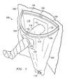
- FIGURE 1 is a perspective view of a surgical drape 100 being utilized during a surgical procedure according to one embodiment of the present invention.
- surgical drape 100 is being utilized during knee surgery; however, surgical drape 100 may be utilized during other surgical procedures or other medical procedures.
- the term surgery as used herein may mean any suitable medical procedures.
- Surgical drape 100 functions to collect surgical fluids, bodily fluids and/or tissue, and other suitable fluids or materials encountered during surgery.
- surgical drape 100 includes a fluid collection pouch 102, a plurality of inflatable bladders 104, a pair of pumps 106, and a patient drape 108.
- Fluid collection pouch 102 is illustrated in FIGURE 1 to be a generally coneshaped pouch formed from a low density polyethylene.
- fluid collection 102 may be any suitable shape and may be formed from any suitable fluid-impervious material.
- Fluid collection pouch 102 may also be formed from a transparent material, translucent material, or an opaque material.
- Fluid collection pouch includes an open end 110 that allows a surgeon, a doctor, or other suitable medical personnel to access the surgical area.
- a perimeter of open end 110 may include a channel 112 that houses inflatable bladder 104.
- open end 110 of fluid collection pouch 102 may be curled and sealed back to itself or may be formed in other suitable manners.
- Channel 112 may alternatively be a separate element that is coupled to fluid collection pouch 102.
- Drainage port 114 At the lower end of fluid collection pouch 102 is a drainage port 114 that facilitates the draining of any fluids collected during surgery. Drainage port 114 may facilitate the draining of the fluid by gravity or by the coupling of a suction device to drainage port 114. Drainage port 114 may be any suitable fitting that is coupled to fluid collection pouch 102 in any suitable manner.
- Fluid collection pouch 102 also includes opposed apertures 116 formed in its wall. Apertures 116, are adapted to accept a limb 118 of a patient to facilitate surgery. Surrounding apertures 116 may be a flexible material 120 that conforms to the patient's limb 118 in a such a manner that it prevents surgical and/or bodily fluids from leaking between patient's limb 118 and apertures 116. Flexible material 120, which may be any suitable size and shape, may be formed from any suitable material, such as an elasticized polymer. In a particular embodiment, flexible material 120 is formed from KratonTM manufactured by Shell Chemical Company.
- Inflatable bladders 104 substantially surround the perimeter of open end 110 of fluid collection pouch 102.
- the function of inflatable bladders 104 is to allow a surgeon or other medical personnel to deform the perimeter of open end 110 with the assurance that it will reform to its original shape after deforming. For example, if a surgeon needs to position a surgical tool in a certain position for surgery, then a portion of the perimeter of open end 110 will be contorted because of the hand position of a surgeon or the position of a surgical tool adjacent the surgical area. When the surgical tool is removed or the surgeon steps away from the surgical area, inflatable bladders 104 reforms to its natural position as a result of the air pressure therein.
- Inflatable bladders 104 are generally elongated air bladders having any suitable length that are formed from any material suitable to contain pressurized air therein.
- inflatable bladders 104 are housed within channel 112 around the perimeter of open end 110.
- inflatable bladders 104 may be directly coupled to fluid collection pouch 102 around the perimeter of open end 110 in any suitable manner. In other embodiments, one or more inflatable bladders 104 may be disposed generally vertically down, or generally horizontally around, the wall of collection pouch 102 to add additional stiffness to the wall of collection pouch 102.
- Pumps 106 are coupled to inflatable bladders 104 in any suitable manner and are operable to inflate inflatable bladders 104 in any suitable manner, such as the manner described in U.S. Patent No. 5,144,708 (the '708 patent) issued to Pekar and assigned to Dielectrics Industries of Chicopee, Massachusetts. Any suitable type of pump 106 is contemplated by the present invention, as well as other suitable types of inflating devices. Various examples of pumps 106 are shown and described below in conjunction with FIGURES 2B through 2E . In the embodiment illustrated in FIGURE 1 , each pump 106 includes an open cell foam structure disposed between a pair of plastic sheets, with one of the plastic sheets having an aperture formed therein to allow ambient air to enter the open cell foam.
- a check valve (such as the one disclosed in the '708 patent) is coupled to one end of the pump to allow air within the open cell foam structure to enter into inflatable bladder 104.
- the check valve prevents air within inflatable bladder 104 from traveling into pump 106. Accordingly, in operation, a user places his or her finger or thumb over the aperture in one of the plastic sheets and depresses the open cell foam structure so that air is pushed through the check valve and into inflatable bladder 104. The user would then release the pressure exerted on the open cell foam structure and remove his or her finger from over the aperture so that ambient air may fill the open cell foam structure. The process above is then repeated until a desired pressure is obtained within inflatable bladder 104.
- pumps 106 may be utilized.
- pump 106 is generally rectangular in shape; however, any suitably shaped pump may be utilized.
- pumps 106 may either be housed within channel 112 or, in an embodiment where channel 112 does not exist, be coupled to a perimeter of open end 110 of fluid collection pouch 102 in any suitable manner.
- the present invention also contemplates pumps 106 being external to inflatable bladders 104 and/or channel 112, such as those shown and described below in conjunction with FIGURES 2C through 2E ; however, it is desirable to house pumps 106 within channel 112 because this makes the packaging and shipping of surgical drape 100 easier.
- housing pumps 106 within channel 112 provides a more convenient way of inflating inflatable bladders 104 as well as eliminating any interference problems with a surgical procedure.
- Channel 112 may also protect pumps 106 from surgical and/or bodily fluids during surgery.
- Patient drape 108 may be coupled to fluid collection pouch 102 in any suitable manner depending on what portion of a patient's body that patient drape 108 is to protect.
- Patient drape 108 may be any suitable shape and may be formed from any suitable material. As illustrated in FIGURE 1 , patient drape 108 shields the rest of the patient's body from the surgical area.
- Surgical drape 100 will generally be packaged and shipped to a prospective user with inflatable bladders 104 in a deflated state, which is shown in FIGURE 2A .
- Packaging and shipping surgical drape 100 with deflated inflatable bladders 104 is easier and less expensive than packaging and shipping previous surgical drapes that had foam material rims.
- Pumps 106 are utilized to inflate inflatable bladders 104.
- FIGURES 2B through 2E illustrate inflatable bladders 104 being inflated by various examples of pumps 106.
- a user 200 simply uses his or her fingers and thumb to alternately squeeze and release pump 106 to suck in ambient air from outside pump 106 into pump 106 and through a check valve coupled to pump 106 and into inflatable bladders 104. This pumping continues until a desired stiffness of inflatable bladders 104 is obtained.
- user 200 may utilize a suitable squeeze bulb 210 having a suitable check valve to pump ambient air into inflatable bladders 104.
- FIGURE 2D Another type of pump 106 is illustrated in FIGURE 2D .
- a hand pump 220 may be utilized by user 200 to pump air into inflatable bladders 104.
- Hand pump 220 may be any suitable hand pump, such as those used to inflate pool rafts, basketballs, and the like.
- a compressed air source 230 may be utilized by user 200 to inflate inflatable bladders 204.
- Any suitable compressed air source 230 is contemplated by the present invention.
- Other suitable example pumps 106 are chemical reaction type pumps, such as those with an acid and base, and a gas cartridge, such as a CO 2 cartridge. In other embodiments, no pump is utilized.
- air from a human's lungs may be utilized to inflate inflatable bladders 104.
- surgical drape 100 may then be placed in its desired position with respect to a patient with collection pouch 102 underneath the surgical site. Surgical and/or bodily fluids may then be collected by collection pouch 102 during the surgical procedure. After the surgical procedure is completed, fluids may be drained off and surgical drape 100 discarded. In other embodiments, fluids are drained off and surgical drape 100 is re-used for another surgical procedure.
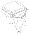
- FIGURE 3 is a perspective view of another embodiment of a surgical drape 300 being utilized during a surgical procedure.
- surgical drape 300 is coupled to a substrate 302.
- Substrate 302 may be any suitable substrate, such as a bed used in obstetrics, gynecology, or urology, or a surgical drape.
- Other intended uses for surgical drape 300 are contemplated by the present invention.
- Surgical drape 300 includes a fluid collection pouch 304, an inflatable bladder 306, a pump 308, and a flap 310.
- Fluid collection pouch 304 is illustrated in FIGURE 3 to be the general shape of a half of a cone; however, other suitable shapes may be utilized. Fluid collection pouch 304 is similar to fluid collection pouch 102 of FIGURE 1 and functions in a similar manner. However, since fluid collection pouch 304 is contemplated for obstetrical, gynecological, or urological procedures, it differs from fluid collection pouch 102 in that it does not have apertures in its wall for a patient's limb. Otherwise, fluid may leak out of fluid collection pouch 304. Fluid collection pouch 304 includes an open end 314 that collects fluid from a surgical site and directs it into a fluid collection pouch 304. Fluid collection pouch 304 does include a drainage port 312 at a lower end thereof. Drainage port 312 is similar to drainage port 114 of FIGURE 1 and functions in a similar manner.
- a channel 316 surrounds approximately one-half of the perimeter of open end 314 and functions to house inflatable bladder 306.
- Channel 316 is similar to channel 112 of surgical drape 100 and may be formed in a similar manner.
- Channel 316 only surrounds approximately one-half of the perimeter of open end 314 because the other approximately one-half of the perimeter comprises flap 310.
- Flap 310 which may be any suitable length and width, includes an adhesive strip 318 that allows surgical drape 300 to be coupled to substrate 302 or other suitable medical platform. Flap 310 and adhesive strip 318 may both be formed from any suitable material.
- Inflatable bladder 306 is similar to inflatable bladders 104 of FIGURE 1 and is inflated by pump 308, which is similar to pumps 106 in FIGURE 1 . Any suitable number of inflatable bladders 306 may be utilized and any suitable number of pumps 308 may be utilized. Similar to surgical drape 100, surgical drape 300 will generally be packaged and shipped with inflatable bladder 306 being in a deflated state. Pump 308 is utilized by medical personnel to inflate inflatable bladder 306 to a desired stiffness. Drape 300 may be attached by flap 310 prior to or after inflation. Surgical drape 300 may then be attached to substrate 302 by flap 310 and adhesive strip 318. Surgical drape 300 is positioned in such a manner that open end 314 is underneath the desired surgical area.
- fluid collection pouch 304 During the surgical procedure, surgical fluids and/or bodily fluids fall into fluid collection pouch 304 and collect near its bottom end. Drainage port 312 may then be used to drain the fluids off, or surgical drape 300 may be disposed of without draining the fluid.
- the advantages of using surgical drape 200 of FIGURE 3 are similar to those proffered above in conjunction with surgical drape 100 of FIGURE 1 .
Landscapes
- Health & Medical Sciences (AREA)
- Surgery (AREA)
- Life Sciences & Earth Sciences (AREA)
- Medical Informatics (AREA)
- Biomedical Technology (AREA)
- Heart & Thoracic Surgery (AREA)
- Engineering & Computer Science (AREA)
- Molecular Biology (AREA)
- Animal Behavior & Ethology (AREA)
- General Health & Medical Sciences (AREA)
- Public Health (AREA)
- Veterinary Medicine (AREA)
- External Artificial Organs (AREA)
- Media Introduction/Drainage Providing Device (AREA)
- Massaging Devices (AREA)
Abstract
Description
- The present invention relates generally to the field of surgical drapes, and more particularly to a surgical drape having a fluid collection pouch with an inflatable rim.
- Numerous surgeries and other medical procedures are performed in hospitals and medical buildings everyday across the world. Depending on the type of surgery being performed, there is usually surgical and/or bodily fluids that are encountered during the procedure. Medical personnel use collection pouches to collect these fluids to prevent spillage of the fluids, to keep the fluids away from the patient, and to protect operating room personnel. Medical personnel, therefore, desire that these collection pouches be easy to use and perform their function in a reliable manner.
- Some previous collection pouches have malleable wires around a perimeter of their open end that allow medical personnel to shape the perimeter of the collection pouch in a desired configuration. However, once the malleable wire is shaped in a certain way, it stays that way or collapses under pressure. Collection pouches having these malleable wires may be inadequate to conform adequately to a portion of a patient's body or to fully support the pouch when open. In addition, when a surgeon is finished with a particular positioning of the surgical tool, then one portion of the perimeter of the open end may be in such a position that surgical and/or bodily fluids leak out of the collection pouch and onto the floor, which is undesirable.
- Some previous collection pouches have a foam material around a perimeter of their open end that offered some stiffness to the perimeter so that the pouch could stay open, yet be resilient enough to allow a surgeon to position his or her hand or a surgical tool without much resistance from the foam material. However, these foamrimmed pouches were unreliable. Because of the environment the pouch is used in, the foam material has a tendency to crackle and peel to the extent that some of the foam material may fall into the surgical area, which is undesirable. To address this problem, the foam material was encased within a housing. However, these types of pouches had packaging and shipping problems, as well as additional manufacturing expense. An example of a prior surgical pouch approach for collecting fluids can be found in
US 5002069 , the two part form of claim 1 is based on this document. In a different field,US 5558654 shows collection of waste products. - According to one embodiment of the invention, an apparatus used for collecting fluids during a medical procedure includes a fluid collection pouch having an open end, an inflatable bladder substantially surrounding a perimeter of the open end, and a pump coupled to the inflatable bladder. The pump is operable to inflate the inflatable bladder.
- According to another embodiment of the invention, an apparatus used for collecting fluids during a medical procedure includes a fluid collection pouch having an open end with a perimeter, a channel surrounding approximately one half of the perimeter of the open end, an inflatable bladder disposed within the channel, and a pump disposed within the channel and coupled to the inflatable bladder. The pump is operable to inflate the inflatable bladder.
- Embodiments of the invention provide a number of technical advantages. Embodiments of the invention may include all, some, or none of these advantages. One technical advantage is a surgical drape that has "shape memory." Surgeons or other medical personnel oftentimes have to reform the rim of the collection pouch to facilitate specific positioning of a surgical instrument. Having one or more inflatable bladders around a perimeter of a fluid collection pouch allows a surgeon or other medical personnel to deform the inflatable rim with the assurance the rim will reform to its original shape after the deforming. This helps to prevent spillage of surgical and/or other fluids from the surgical site in addition to saving the surgeon valuable time from not having to reshape the rim themselves. An inflatable rim also facilitates better conformability. The inflatable rim naturally follows the contours of a patients body parts, which may help to avoid any fluids from toughing the patient or the bed that the patient is lying on. A surgical drape having an inflatable rim also may be packaged and shipped with the inflatable rim in a deflated state, which is easier and less expensive than shipping surgical drapes having foam rims,
- Other technical advantages are readily apparent to one skilled in the art from the following figures, descriptions, and claims.
- For a more complete understanding of the invention, and for further features and advantages, reference is now made to the following description, taken in conjunction with the accompanying drawings, in which:
-
FIGURE 1 is a perspective view of a surgical drape having a fluid collection pouch with an inflatable rim being used to collect fluids during a surgical procedure in accordance with one embodiment of the present invention; -
FIGURE 2A is a perspective view of the inflatable rim of the collection pouch ofFIGURE 1 showing the inflatable rim in a deflated state; -
FIGURES 2B through 2E are perspective views of the inflatable rim of the collection pouch ofFIGURE 1 being inflated by a user in accordance with various embodiments of the present invention; and -
FIGURE 3 is a perspective view of another surgical drape having a fluid collection pouch with an inflatable rim being used to collect fluids during a surgical procedure in accordance with another embodiment of the present invention. - Example embodiments of the present invention and their advantages are best understood by referring now to
FIGURES 1-3 of the drawings, in which like numerals refer to like parts. -
FIGURE 1 is a perspective view of asurgical drape 100 being utilized during a surgical procedure according to one embodiment of the present invention. In the illustrated embodiment,surgical drape 100 is being utilized during knee surgery; however,surgical drape 100 may be utilized during other surgical procedures or other medical procedures. The term surgery as used herein may mean any suitable medical procedures.Surgical drape 100 functions to collect surgical fluids, bodily fluids and/or tissue, and other suitable fluids or materials encountered during surgery. As illustrated inFIGURE 1 ,surgical drape 100 includes afluid collection pouch 102, a plurality ofinflatable bladders 104, a pair ofpumps 106, and apatient drape 108. -
Fluid collection pouch 102 is illustrated inFIGURE 1 to be a generally coneshaped pouch formed from a low density polyethylene. However,fluid collection 102 may be any suitable shape and may be formed from any suitable fluid-impervious material.Fluid collection pouch 102 may also be formed from a transparent material, translucent material, or an opaque material. Fluid collection pouch includes anopen end 110 that allows a surgeon, a doctor, or other suitable medical personnel to access the surgical area. A perimeter ofopen end 110 may include achannel 112 that housesinflatable bladder 104. To formchannel 112,open end 110 offluid collection pouch 102 may be curled and sealed back to itself or may be formed in other suitable manners. Channel 112 may alternatively be a separate element that is coupled tofluid collection pouch 102. - At the lower end of
fluid collection pouch 102 is a drainage port 114 that facilitates the draining of any fluids collected during surgery. Drainage port 114 may facilitate the draining of the fluid by gravity or by the coupling of a suction device to drainage port 114. Drainage port 114 may be any suitable fitting that is coupled tofluid collection pouch 102 in any suitable manner. -
Fluid collection pouch 102 also includesopposed apertures 116 formed in its wall.Apertures 116, are adapted to accept alimb 118 of a patient to facilitate surgery. Surroundingapertures 116 may be aflexible material 120 that conforms to the patient'slimb 118 in a such a manner that it prevents surgical and/or bodily fluids from leaking between patient'slimb 118 andapertures 116.Flexible material 120, which may be any suitable size and shape, may be formed from any suitable material, such as an elasticized polymer. In a particular embodiment,flexible material 120 is formed from Kraton™ manufactured by Shell Chemical Company. -
Inflatable bladders 104 substantially surround the perimeter ofopen end 110 offluid collection pouch 102. The function ofinflatable bladders 104 is to allow a surgeon or other medical personnel to deform the perimeter ofopen end 110 with the assurance that it will reform to its original shape after deforming. For example, if a surgeon needs to position a surgical tool in a certain position for surgery, then a portion of the perimeter ofopen end 110 will be contorted because of the hand position of a surgeon or the position of a surgical tool adjacent the surgical area. When the surgical tool is removed or the surgeon steps away from the surgical area,inflatable bladders 104 reforms to its natural position as a result of the air pressure therein. This helps to prevent spillage of surgical and/or other fluids from the surgical area in addition to saving the surgeon or other medical personnel valuable time from not having to re-shape the perimeter ofopen end 110 as in previous surgical drapes that had malleable rims. The malleable rims also do not prevent spillage as well asinflatable bladders 104. Previous surgical drapes having foam material rims did fairly well to prevent spillage; however, the foam rims had a tendency to be brittle and to crackle, which sometimes led to pieces of the foam falling into the surgical area. The foam material may be encased within a housing to prevent pieces of the foam falling into the surgical area. However, this adds to the manufacturing expense. The teachings of the present invention recognize that incorporatinginflatable bladders 104 around a perimeter ofopen end 110 may cause greater expense in manufacturingsurgical drape 100; however, the applicants believe thatsurgical drape 100 may be manufactured in a cost-effective manner. - In the illustrated embodiment, four
inflatable bladders 104 are shown; however, one or any suitable number ofinflatable bladders 104 may be utilized.Inflatable bladders 104 are generally elongated air bladders having any suitable length that are formed from any material suitable to contain pressurized air therein. Although the teachings of the present invention recognize that medical personnel may not desire to usesurgical drape 100 withinflatable bladders 104 because of the risk of puncturing them due to the sharp objects often employed in medical procedures, steps may be taken to mitigate this risk by, for example, using a thicker plastic to forminflatable bladders 104. In the illustrated embodiment,inflatable bladders 104 are housed withinchannel 112 around the perimeter ofopen end 110. However, in an embodiment wherechannel 112 does not exist,inflatable bladders 104 may be directly coupled tofluid collection pouch 102 around the perimeter ofopen end 110 in any suitable manner. In other embodiments, one or moreinflatable bladders 104 may be disposed generally vertically down, or generally horizontally around, the wall ofcollection pouch 102 to add additional stiffness to the wall ofcollection pouch 102. -
Pumps 106 are coupled toinflatable bladders 104 in any suitable manner and are operable to inflateinflatable bladders 104 in any suitable manner, such as the manner described inU.S. Patent No. 5,144,708 (the '708 patent) issued to Pekar and assigned to Dielectrics Industries of Chicopee, Massachusetts. Any suitable type ofpump 106 is contemplated by the present invention, as well as other suitable types of inflating devices. Various examples ofpumps 106 are shown and described below in conjunction withFIGURES 2B through 2E . In the embodiment illustrated inFIGURE 1 , eachpump 106 includes an open cell foam structure disposed between a pair of plastic sheets, with one of the plastic sheets having an aperture formed therein to allow ambient air to enter the open cell foam. A check valve (such as the one disclosed in the '708 patent) is coupled to one end of the pump to allow air within the open cell foam structure to enter intoinflatable bladder 104. The check valve prevents air withininflatable bladder 104 from traveling intopump 106. Accordingly, in operation, a user places his or her finger or thumb over the aperture in one of the plastic sheets and depresses the open cell foam structure so that air is pushed through the check valve and intoinflatable bladder 104. The user would then release the pressure exerted on the open cell foam structure and remove his or her finger from over the aperture so that ambient air may fill the open cell foam structure. The process above is then repeated until a desired pressure is obtained withininflatable bladder 104. - Although two
pumps 106 are shown inFIGURE 1 , onepump 106 or any suitable number ofpumps 106 may be utilized. In one embodiment, pump 106 is generally rectangular in shape; however, any suitably shaped pump may be utilized. Similarly toinflatable bladders 104, pumps 106 may either be housed withinchannel 112 or, in an embodiment wherechannel 112 does not exist, be coupled to a perimeter ofopen end 110 offluid collection pouch 102 in any suitable manner. The present invention also contemplatespumps 106 being external toinflatable bladders 104 and/orchannel 112, such as those shown and described below in conjunction withFIGURES 2C through 2E ; however, it is desirable to house pumps 106 withinchannel 112 because this makes the packaging and shipping ofsurgical drape 100 easier. In addition,housing pumps 106 withinchannel 112 provides a more convenient way of inflatinginflatable bladders 104 as well as eliminating any interference problems with a surgical procedure.Channel 112 may also protectpumps 106 from surgical and/or bodily fluids during surgery. -
Patient drape 108 may be coupled tofluid collection pouch 102 in any suitable manner depending on what portion of a patient's body thatpatient drape 108 is to protect.Patient drape 108 may be any suitable shape and may be formed from any suitable material. As illustrated inFIGURE 1 ,patient drape 108 shields the rest of the patient's body from the surgical area. -
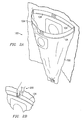
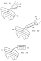
Surgical drape 100 will generally be packaged and shipped to a prospective user withinflatable bladders 104 in a deflated state, which is shown inFIGURE 2A . Packaging and shippingsurgical drape 100 with deflatedinflatable bladders 104 is easier and less expensive than packaging and shipping previous surgical drapes that had foam material rims.Pumps 106 are utilized to inflateinflatable bladders 104.FIGURES 2B through 2E illustrateinflatable bladders 104 being inflated by various examples ofpumps 106. - Referring to
FIGURE 2B , auser 200 simply uses his or her fingers and thumb to alternately squeeze andrelease pump 106 to suck in ambient air fromoutside pump 106 intopump 106 and through a check valve coupled to pump 106 and intoinflatable bladders 104. This pumping continues until a desired stiffness ofinflatable bladders 104 is obtained. Similarly, referring toFIGURE 2C ,user 200 may utilize asuitable squeeze bulb 210 having a suitable check valve to pump ambient air intoinflatable bladders 104. Another type ofpump 106 is illustrated inFIGURE 2D . Ahand pump 220 may be utilized byuser 200 to pump air intoinflatable bladders 104.Hand pump 220 may be any suitable hand pump, such as those used to inflate pool rafts, basketballs, and the like. As illustrated inFIGURE 2E , acompressed air source 230 may be utilized byuser 200 to inflate inflatable bladders 204. Any suitable compressedair source 230 is contemplated by the present invention. Other suitable example pumps 106 are chemical reaction type pumps, such as those with an acid and base, and a gas cartridge, such as a CO2 cartridge. In other embodiments, no pump is utilized. For example, air from a human's lungs may be utilized to inflateinflatable bladders 104. - After the desired stiffness of
inflatable bladders 104 is obtained,surgical drape 100 may then be placed in its desired position with respect to a patient withcollection pouch 102 underneath the surgical site. Surgical and/or bodily fluids may then be collected bycollection pouch 102 during the surgical procedure. After the surgical procedure is completed, fluids may be drained off andsurgical drape 100 discarded. In other embodiments, fluids are drained off andsurgical drape 100 is re-used for another surgical procedure. -
FIGURE 3 is a perspective view of another embodiment of asurgical drape 300 being utilized during a surgical procedure. In the illustrated embodiment,surgical drape 300 is coupled to asubstrate 302.Substrate 302 may be any suitable substrate, such as a bed used in obstetrics, gynecology, or urology, or a surgical drape. Other intended uses forsurgical drape 300 are contemplated by the present invention.Surgical drape 300 includes afluid collection pouch 304, aninflatable bladder 306, apump 308, and aflap 310. -
Fluid collection pouch 304 is illustrated inFIGURE 3 to be the general shape of a half of a cone; however, other suitable shapes may be utilized.Fluid collection pouch 304 is similar tofluid collection pouch 102 ofFIGURE 1 and functions in a similar manner. However, sincefluid collection pouch 304 is contemplated for obstetrical, gynecological, or urological procedures, it differs fromfluid collection pouch 102 in that it does not have apertures in its wall for a patient's limb. Otherwise, fluid may leak out offluid collection pouch 304.Fluid collection pouch 304 includes anopen end 314 that collects fluid from a surgical site and directs it into afluid collection pouch 304.Fluid collection pouch 304 does include adrainage port 312 at a lower end thereof.Drainage port 312 is similar to drainage port 114 ofFIGURE 1 and functions in a similar manner. - A
channel 316 surrounds approximately one-half of the perimeter ofopen end 314 and functions to houseinflatable bladder 306.Channel 316 is similar tochannel 112 ofsurgical drape 100 and may be formed in a similar manner.Channel 316 only surrounds approximately one-half of the perimeter ofopen end 314 because the other approximately one-half of the perimeter comprisesflap 310.Flap 310, which may be any suitable length and width, includes anadhesive strip 318 that allowssurgical drape 300 to be coupled tosubstrate 302 or other suitable medical platform.Flap 310 andadhesive strip 318 may both be formed from any suitable material. -
Inflatable bladder 306 is similar toinflatable bladders 104 ofFIGURE 1 and is inflated bypump 308, which is similar topumps 106 inFIGURE 1 . Any suitable number ofinflatable bladders 306 may be utilized and any suitable number ofpumps 308 may be utilized. Similar tosurgical drape 100,surgical drape 300 will generally be packaged and shipped withinflatable bladder 306 being in a deflated state.Pump 308 is utilized by medical personnel to inflateinflatable bladder 306 to a desired stiffness.Drape 300 may be attached byflap 310 prior to or after inflation.Surgical drape 300 may then be attached tosubstrate 302 byflap 310 andadhesive strip 318.Surgical drape 300 is positioned in such a manner thatopen end 314 is underneath the desired surgical area. During the surgical procedure, surgical fluids and/or bodily fluids fall intofluid collection pouch 304 and collect near its bottom end.Drainage port 312 may then be used to drain the fluids off, orsurgical drape 300 may be disposed of without draining the fluid. The advantages of usingsurgical drape 200 ofFIGURE 3 are similar to those proffered above in conjunction withsurgical drape 100 ofFIGURE 1 . - Although embodiments of the invention and some of their advantages are described in detail, a person skilled in the art could make various alterations, additions, and omissions without departing from scope of the present invention as defined by the appended claims.
Claims (16)
- A system used for collecting fluids during a medical procedure, comprising:a patient drape (108) configured to shield a portion of a patient's body during a medical procedure;a fluid collection pouch (102) coupled to the patient drape (108) and having an open end (110), the fluid collection pouch (102) having at least one aperture (116) formed in a wall of the fluid collection pouch (102), the aperture (116) adapted to accept a limb (118) of a patient, characterised by,an elongated inflatable bladder (104) disposed around a perimeter of the open end (110); andan inflating device (106) for inflating the inflatable bladder (104).
- The system of Claim 1, further comprising a channel (112) surrounding a perimeter of the open end (110).
- The system of Claim 2, wherein the elongated inflatable bladder (104)is disposed in the channel (112).
- The system of Claim 3, wherein the inflating device (106) is disposed in the channel (112) and coupled to the elongated inflatable bladder (104).
- The system of claim 1, further comprising a drainage port (114) coupled to a wall of the fluid collection pouch (102) for draining fluid from the fluid collection pouch (102).
- The system of claim 1, wherein the inflating device (106) is a carbon dioxide cartridge.
- The system of claim 1, wherein the inflating device (106) is a squeeze bulb (210).
- The system of claim 1, wherein the inflating device (106) is a hand pump (220).
- The system of claim 1, wherein the inflating device (106) is a compressed air source (230).
- The system of claim 1, wherein the inflating device (106) is a chemical reaction type pump.
- The system of claim 1, wherein the inflating device (106) is a pump.
- The system of Claim 11, wherein the pump includes an open cell foam disposed between two sheets.
- The system of Claim 12, wherein one of the sheets includes an aperture therein to allow ambient air to enter the open cell foam.
- The system of Claim 1, wherein the at least one aperture (116) is a pair of opposed apertures (116) in the wall of the fluid collection pouch (102).
- The system of Claim 1, further comprising:a flap (310) having an adhesive strip (318) to secure the fluid collection pouch (102) to a substrate (302).
- The system of Claim 1, wherein the inflatable bladder (104) comprises a plurality of inflatable bladders (104) each having separate inflating devices (106).
Applications Claiming Priority (5)
| Application Number | Priority Date | Filing Date | Title |
|---|---|---|---|
| US655495 | 2000-09-05 | ||
| US235309 | 2002-09-05 | ||
| US10/235,309 US20040045557A1 (en) | 2002-09-05 | 2002-09-05 | Surgical drape having a fluid collection pouch with an inflatable rim |
| US10/655,495 US7096871B2 (en) | 2002-09-05 | 2003-09-04 | Surgical drape having a fluid collection pouch with an inflatable rim |
| PCT/US2003/027927 WO2004021912A1 (en) | 2002-09-05 | 2003-09-05 | Surgical drape having a fluid collection pouch with an inflatable rim |
Publications (2)
| Publication Number | Publication Date |
|---|---|
| EP1545375A1 EP1545375A1 (en) | 2005-06-29 |
| EP1545375B1 true EP1545375B1 (en) | 2011-03-23 |
Family
ID=31980972
Family Applications (1)
| Application Number | Title | Priority Date | Filing Date |
|---|---|---|---|
| EP03749466A Expired - Lifetime EP1545375B1 (en) | 2002-09-05 | 2003-09-05 | Surgical drape having a fluid collection pouch with an inflatable rim |
Country Status (7)
| Country | Link |
|---|---|
| US (2) | US7690380B2 (en) |
| EP (1) | EP1545375B1 (en) |
| JP (1) | JP2005537869A (en) |
| AU (1) | AU2003268500B2 (en) |
| CA (1) | CA2497341C (en) |
| MX (1) | MXPA05002464A (en) |
| WO (1) | WO2004021912A1 (en) |
Families Citing this family (19)
| Publication number | Priority date | Publication date | Assignee | Title |
|---|---|---|---|---|
| US7409953B2 (en) * | 2003-12-16 | 2008-08-12 | Kimberly-Clark Worldwide, Inc. | Surgical drape having an expandable member |
| DE602006019308D1 (en) | 2005-11-30 | 2011-02-10 | Urotech Pty Ltd | UROLOGICAL CLOTH |
| JP5291332B2 (en) * | 2007-12-25 | 2013-09-18 | 株式会社リブドゥコーポレーション | Medical pouch and drape |
| CA2732936C (en) * | 2008-08-04 | 2016-11-29 | Asap-Norway As | Fluid absorbing sheet |
| US8833707B2 (en) | 2010-07-15 | 2014-09-16 | Allen Medical Systems, Inc. | Disposable urology drainage bag |
| US9125787B2 (en) | 2011-09-30 | 2015-09-08 | Covidien Lp | Compression garment having a foam layer |
| JP5513581B2 (en) * | 2012-10-24 | 2014-06-04 | 株式会社リブドゥコーポレーション | Medical pouch and drape |
| US9402779B2 (en) | 2013-03-11 | 2016-08-02 | Covidien Lp | Compression garment with perspiration relief |
| US10182877B2 (en) * | 2013-05-30 | 2019-01-22 | The Charlotte-Mecklenburg Hospital Authority | Surgical drape for collecting discharged fluid |
| US11109931B2 (en) * | 2015-11-02 | 2021-09-07 | Work Fluidics, LLC | Multi-layer pre-drape apparatus and process |
| US10912879B2 (en) * | 2016-10-13 | 2021-02-09 | Drue Maureen Orwig | Collection device for use in irrigation and drainage procedures |
| US10729507B2 (en) | 2017-01-12 | 2020-08-04 | Warsaw Orthopedic, Inc. | Surgical draping system and method for using same |
| EP3664648B1 (en) * | 2017-08-10 | 2023-04-26 | PROCEPT BioRobotics Corporation | Surgical drape |
| USD912255S1 (en) | 2018-05-09 | 2021-03-02 | Moleculight, Inc. | Darkening drape |
| USD903863S1 (en) * | 2019-01-15 | 2020-12-01 | Moleculight Inc. | Adapter for supporting a darkening drape |
| EP3804803B1 (en) * | 2019-10-10 | 2026-01-28 | Serres Oy | A valve for a pouch for collecting a fluid flow and a use of the valve |
| KR102408064B1 (en) * | 2020-04-03 | 2022-06-10 | 전북대학교산학협력단 | Operation drape for delivery |
| US11471234B2 (en) | 2020-09-01 | 2022-10-18 | Medline Industries Lp | Dual amniotic and placenta fluid measurement parturition drape |
| USD1047150S1 (en) * | 2020-09-01 | 2024-10-15 | Medline Industries Lp | Parturition drape |
Citations (1)
| Publication number | Priority date | Publication date | Assignee | Title |
|---|---|---|---|---|
| US5002069A (en) * | 1990-04-30 | 1991-03-26 | Baxter International, Inc. | Adjustable fluid control pouch |
Family Cites Families (23)
| Publication number | Priority date | Publication date | Assignee | Title |
|---|---|---|---|---|
| US542202A (en) | 1895-07-02 | John henry morrison | ||
| US763304A (en) | 1903-01-03 | 1904-06-21 | Meinecke & Co | Surgical or operating pad or cushion. |
| US762737A (en) | 1903-04-11 | 1904-06-14 | Meinecke And Company | Operating pad or receptacle. |
| US759084A (en) | 1903-05-16 | 1904-05-03 | Goodyear S India Rubber Glove Mfg Co | Surgical operating-cushion. |
| US1741836A (en) | 1927-03-02 | 1929-12-31 | Em Dee Supply Company | Surgical operating cushion |
| US1864434A (en) | 1927-03-29 | 1932-06-21 | John R Foley | Hospital pad and ring |
| US2658512A (en) | 1951-06-28 | 1953-11-10 | Tcheong Joana D Arc Yok Heng | Washing apparatus with cushion and drainage facilities |
| US3418663A (en) * | 1966-02-25 | 1968-12-31 | Nathaniel C. Scott | Disposable body waste receptacle |
| US3816858A (en) | 1973-03-16 | 1974-06-18 | M Martin | Inflatable hair washing aid |
| US4974604A (en) * | 1987-10-29 | 1990-12-04 | Johnson & Johnson Medical Inc. | Surgical drape with fluid collection system |
| US5342385A (en) | 1991-02-05 | 1994-08-30 | Norelli Robert A | Fluid-expandable surgical retractor |
| US5144708A (en) | 1991-02-26 | 1992-09-08 | Dielectrics Industries | Check valve for fluid bladders |
| US5419343A (en) * | 1992-03-18 | 1995-05-30 | Microtek Medical, Inc. | Arthroscopy drape and collection pouch |
| GB2269579A (en) * | 1992-08-14 | 1994-02-16 | John Richard Wickham Hardy | Waste product collection unit |
| US5372487A (en) | 1993-06-10 | 1994-12-13 | Dielectrics Industries | Inlet check valve for pump mechanism |
| US5620010A (en) | 1993-08-19 | 1997-04-15 | Aquintel, Inc. | Disposable surgical drape |
| US5514081A (en) | 1994-10-07 | 1996-05-07 | D'mannco, Inc. | Elbow orthosis having an inflatable bladder support and method of use |
| WO1997009001A2 (en) * | 1995-09-05 | 1997-03-13 | Kimberly-Clark Worldwide, Inc. | Surgical drape and method of assembly |
| US6070586A (en) * | 1996-06-05 | 2000-06-06 | Lingeman Medical Products, Inc. | Fluid control drape with conforming lip |
| US6442962B1 (en) | 2000-02-11 | 2002-09-03 | Margaret Gaetke | Portable salad bar |
| US6725864B2 (en) * | 2001-03-15 | 2004-04-27 | Allegiance Corporation | Surgical shoulder drape with pouch |
| US6782640B2 (en) | 2001-09-12 | 2004-08-31 | Craig D. Westin | Custom conformable device |
| US7409953B2 (en) * | 2003-12-16 | 2008-08-12 | Kimberly-Clark Worldwide, Inc. | Surgical drape having an expandable member |
-
2003
- 2003-09-05 EP EP03749466A patent/EP1545375B1/en not_active Expired - Lifetime
- 2003-09-05 AU AU2003268500A patent/AU2003268500B2/en not_active Expired
- 2003-09-05 JP JP2004534679A patent/JP2005537869A/en active Pending
- 2003-09-05 CA CA2497341A patent/CA2497341C/en not_active Expired - Lifetime
- 2003-09-05 WO PCT/US2003/027927 patent/WO2004021912A1/en not_active Ceased
- 2003-09-05 MX MXPA05002464A patent/MXPA05002464A/en active IP Right Grant
-
2006
- 2006-08-28 US US11/467,800 patent/US7690380B2/en not_active Expired - Lifetime
-
2010
- 2010-02-02 US US12/698,266 patent/US8020561B2/en not_active Expired - Fee Related
Patent Citations (1)
| Publication number | Priority date | Publication date | Assignee | Title |
|---|---|---|---|---|
| US5002069A (en) * | 1990-04-30 | 1991-03-26 | Baxter International, Inc. | Adjustable fluid control pouch |
Also Published As
| Publication number | Publication date |
|---|---|
| JP2005537869A (en) | 2005-12-15 |
| EP1545375A1 (en) | 2005-06-29 |
| US20070017529A1 (en) | 2007-01-25 |
| AU2003268500B2 (en) | 2009-09-17 |
| US7690380B2 (en) | 2010-04-06 |
| CA2497341A1 (en) | 2004-03-18 |
| MXPA05002464A (en) | 2005-06-03 |
| US8020561B2 (en) | 2011-09-20 |
| US20100137820A1 (en) | 2010-06-03 |
| CA2497341C (en) | 2010-07-06 |
| AU2003268500A1 (en) | 2004-03-29 |
| WO2004021912A1 (en) | 2004-03-18 |
Similar Documents
| Publication | Publication Date | Title |
|---|---|---|
| US8020561B2 (en) | Surgical drape having a fluid collection pouch with an inflatable rim | |
| US7096871B2 (en) | Surgical drape having a fluid collection pouch with an inflatable rim | |
| US11304774B2 (en) | Method of using surgical drape | |
| US20090082634A1 (en) | Surgical method | |
| US5316541A (en) | Enclosure for surgical procedures | |
| CN101180015B (en) | An appliance for irrigation and/or drainage | |
| JP3415839B2 (en) | Waste collection unit | |
| EP2042103B1 (en) | Inflatable medical device | |
| WO2004105622A1 (en) | Asymmetrically inflating flexi-tip gastroplasty calibration tube | |
| US20240180539A1 (en) | A system and tamponade for treating penetrating wounds | |
| US20100042058A1 (en) | System and Method for Draining Bodily Fluids from a Treatment Site | |
| EP1085924B1 (en) | Shape-adaptable topical hyperbaric oxygen chamber | |
| JP3989717B2 (en) | Medical discharge tool | |
| CN216358609U (en) | Lower limb wound emptier | |
| CN215821061U (en) | Ultrasonic cutting surgery hemostatic device | |
| CN101355908B (en) | Abdominal sac to stop the patient from bleeding | |
| US20230371940A1 (en) | Joint distraction device | |
| CN203447620U (en) | Drainage-pipe fixing cushion |
Legal Events
| Date | Code | Title | Description |
|---|---|---|---|
| PUAI | Public reference made under article 153(3) epc to a published international application that has entered the european phase |
Free format text: ORIGINAL CODE: 0009012 |
|
| 17P | Request for examination filed |
Effective date: 20050322 |
|
| AK | Designated contracting states |
Kind code of ref document: A1 Designated state(s): AT BE BG CH CY CZ DE DK EE ES FI FR GB GR HU IE IT LI LU MC NL PT RO SE SI SK TR |
|
| AX | Request for extension of the european patent |
Extension state: AL LT LV MK |
|
| DAX | Request for extension of the european patent (deleted) | ||
| RIN1 | Information on inventor provided before grant (corrected) |
Inventor name: GIL, MICHAEL, A. Inventor name: LEE, DAN, R. Inventor name: COOPER, LLOYD, G., B. Inventor name: COX, LEWIS, DORSEY |
|
| 17Q | First examination report despatched |
Effective date: 20070213 |
|
| GRAP | Despatch of communication of intention to grant a patent |
Free format text: ORIGINAL CODE: EPIDOSNIGR1 |
|
| GRAS | Grant fee paid |
Free format text: ORIGINAL CODE: EPIDOSNIGR3 |
|
| GRAA | (expected) grant |
Free format text: ORIGINAL CODE: 0009210 |
|
| AK | Designated contracting states |
Kind code of ref document: B1 Designated state(s): AT BE BG CH CY CZ DE DK EE ES FI FR GB GR HU IE IT LI LU MC NL PT RO SE SI SK TR |
|
| REG | Reference to a national code |
Ref country code: GB Ref legal event code: FG4D |
|
| REG | Reference to a national code |
Ref country code: CH Ref legal event code: EP |
|
| REG | Reference to a national code |
Ref country code: IE Ref legal event code: FG4D |
|
| REF | Corresponds to: |
Ref document number: 60336484 Country of ref document: DE Date of ref document: 20110505 Kind code of ref document: P |
|
| REG | Reference to a national code |
Ref country code: DE Ref legal event code: R096 Ref document number: 60336484 Country of ref document: DE Effective date: 20110505 |
|
| PG25 | Lapsed in a contracting state [announced via postgrant information from national office to epo] |
Ref country code: GR Free format text: LAPSE BECAUSE OF FAILURE TO SUBMIT A TRANSLATION OF THE DESCRIPTION OR TO PAY THE FEE WITHIN THE PRESCRIBED TIME-LIMIT Effective date: 20110624 Ref country code: SE Free format text: LAPSE BECAUSE OF FAILURE TO SUBMIT A TRANSLATION OF THE DESCRIPTION OR TO PAY THE FEE WITHIN THE PRESCRIBED TIME-LIMIT Effective date: 20110323 |
|
| REG | Reference to a national code |
Ref country code: ES Ref legal event code: FG2A Ref document number: 2363498 Country of ref document: ES Kind code of ref document: T3 Effective date: 20110805 |
|
| PG25 | Lapsed in a contracting state [announced via postgrant information from national office to epo] |
Ref country code: CY Free format text: LAPSE BECAUSE OF FAILURE TO SUBMIT A TRANSLATION OF THE DESCRIPTION OR TO PAY THE FEE WITHIN THE PRESCRIBED TIME-LIMIT Effective date: 20110323 Ref country code: BG Free format text: LAPSE BECAUSE OF FAILURE TO SUBMIT A TRANSLATION OF THE DESCRIPTION OR TO PAY THE FEE WITHIN THE PRESCRIBED TIME-LIMIT Effective date: 20110623 Ref country code: SI Free format text: LAPSE BECAUSE OF FAILURE TO SUBMIT A TRANSLATION OF THE DESCRIPTION OR TO PAY THE FEE WITHIN THE PRESCRIBED TIME-LIMIT Effective date: 20110323 Ref country code: FI Free format text: LAPSE BECAUSE OF FAILURE TO SUBMIT A TRANSLATION OF THE DESCRIPTION OR TO PAY THE FEE WITHIN THE PRESCRIBED TIME-LIMIT Effective date: 20110323 Ref country code: AT Free format text: LAPSE BECAUSE OF FAILURE TO SUBMIT A TRANSLATION OF THE DESCRIPTION OR TO PAY THE FEE WITHIN THE PRESCRIBED TIME-LIMIT Effective date: 20110323 |
|
| PG25 | Lapsed in a contracting state [announced via postgrant information from national office to epo] |
Ref country code: BE Free format text: LAPSE BECAUSE OF FAILURE TO SUBMIT A TRANSLATION OF THE DESCRIPTION OR TO PAY THE FEE WITHIN THE PRESCRIBED TIME-LIMIT Effective date: 20110323 |
|
| PG25 | Lapsed in a contracting state [announced via postgrant information from national office to epo] |
Ref country code: EE Free format text: LAPSE BECAUSE OF FAILURE TO SUBMIT A TRANSLATION OF THE DESCRIPTION OR TO PAY THE FEE WITHIN THE PRESCRIBED TIME-LIMIT Effective date: 20110323 Ref country code: PT Free format text: LAPSE BECAUSE OF FAILURE TO SUBMIT A TRANSLATION OF THE DESCRIPTION OR TO PAY THE FEE WITHIN THE PRESCRIBED TIME-LIMIT Effective date: 20110725 |
|
| PG25 | Lapsed in a contracting state [announced via postgrant information from national office to epo] |
Ref country code: SK Free format text: LAPSE BECAUSE OF FAILURE TO SUBMIT A TRANSLATION OF THE DESCRIPTION OR TO PAY THE FEE WITHIN THE PRESCRIBED TIME-LIMIT Effective date: 20110323 Ref country code: RO Free format text: LAPSE BECAUSE OF FAILURE TO SUBMIT A TRANSLATION OF THE DESCRIPTION OR TO PAY THE FEE WITHIN THE PRESCRIBED TIME-LIMIT Effective date: 20110323 Ref country code: CZ Free format text: LAPSE BECAUSE OF FAILURE TO SUBMIT A TRANSLATION OF THE DESCRIPTION OR TO PAY THE FEE WITHIN THE PRESCRIBED TIME-LIMIT Effective date: 20110323 |
|
| PLBE | No opposition filed within time limit |
Free format text: ORIGINAL CODE: 0009261 |
|
| STAA | Information on the status of an ep patent application or granted ep patent |
Free format text: STATUS: NO OPPOSITION FILED WITHIN TIME LIMIT |
|
| 26N | No opposition filed |
Effective date: 20111227 |
|
| PG25 | Lapsed in a contracting state [announced via postgrant information from national office to epo] |
Ref country code: DK Free format text: LAPSE BECAUSE OF FAILURE TO SUBMIT A TRANSLATION OF THE DESCRIPTION OR TO PAY THE FEE WITHIN THE PRESCRIBED TIME-LIMIT Effective date: 20110323 |
|
| REG | Reference to a national code |
Ref country code: DE Ref legal event code: R097 Ref document number: 60336484 Country of ref document: DE Effective date: 20111227 |
|
| PG25 | Lapsed in a contracting state [announced via postgrant information from national office to epo] |
Ref country code: MC Free format text: LAPSE BECAUSE OF NON-PAYMENT OF DUE FEES Effective date: 20110930 |
|
| REG | Reference to a national code |
Ref country code: CH Ref legal event code: PL |
|
| REG | Reference to a national code |
Ref country code: IE Ref legal event code: MM4A |
|
| PG25 | Lapsed in a contracting state [announced via postgrant information from national office to epo] |
Ref country code: LI Free format text: LAPSE BECAUSE OF NON-PAYMENT OF DUE FEES Effective date: 20110930 Ref country code: IE Free format text: LAPSE BECAUSE OF NON-PAYMENT OF DUE FEES Effective date: 20110905 Ref country code: CH Free format text: LAPSE BECAUSE OF NON-PAYMENT OF DUE FEES Effective date: 20110930 |
|
| PG25 | Lapsed in a contracting state [announced via postgrant information from national office to epo] |
Ref country code: LU Free format text: LAPSE BECAUSE OF NON-PAYMENT OF DUE FEES Effective date: 20110905 |
|
| PG25 | Lapsed in a contracting state [announced via postgrant information from national office to epo] |
Ref country code: TR Free format text: LAPSE BECAUSE OF FAILURE TO SUBMIT A TRANSLATION OF THE DESCRIPTION OR TO PAY THE FEE WITHIN THE PRESCRIBED TIME-LIMIT Effective date: 20110323 |
|
| PG25 | Lapsed in a contracting state [announced via postgrant information from national office to epo] |
Ref country code: HU Free format text: LAPSE BECAUSE OF FAILURE TO SUBMIT A TRANSLATION OF THE DESCRIPTION OR TO PAY THE FEE WITHIN THE PRESCRIBED TIME-LIMIT Effective date: 20110323 |
|
| REG | Reference to a national code |
Ref country code: FR Ref legal event code: PLFP Year of fee payment: 14 |
|
| REG | Reference to a national code |
Ref country code: FR Ref legal event code: PLFP Year of fee payment: 15 |
|
| REG | Reference to a national code |
Ref country code: FR Ref legal event code: PLFP Year of fee payment: 16 |
|
| PGFP | Annual fee paid to national office [announced via postgrant information from national office to epo] |
Ref country code: NL Payment date: 20220816 Year of fee payment: 20 |
|
| PGFP | Annual fee paid to national office [announced via postgrant information from national office to epo] |
Ref country code: IT Payment date: 20220811 Year of fee payment: 20 Ref country code: GB Payment date: 20220714 Year of fee payment: 20 Ref country code: DE Payment date: 20220609 Year of fee payment: 20 |
|
| PGFP | Annual fee paid to national office [announced via postgrant information from national office to epo] |
Ref country code: FR Payment date: 20220709 Year of fee payment: 20 |
|
| PGFP | Annual fee paid to national office [announced via postgrant information from national office to epo] |
Ref country code: ES Payment date: 20221004 Year of fee payment: 20 |
|
| REG | Reference to a national code |
Ref country code: DE Ref legal event code: R071 Ref document number: 60336484 Country of ref document: DE |
|
| REG | Reference to a national code |
Ref country code: NL Ref legal event code: MK Effective date: 20230904 |
|
| REG | Reference to a national code |
Ref country code: GB Ref legal event code: PE20 Expiry date: 20230904 Ref country code: ES Ref legal event code: FD2A Effective date: 20230927 |
|
| PG25 | Lapsed in a contracting state [announced via postgrant information from national office to epo] |
Ref country code: GB Free format text: LAPSE BECAUSE OF EXPIRATION OF PROTECTION Effective date: 20230904 Ref country code: ES Free format text: LAPSE BECAUSE OF EXPIRATION OF PROTECTION Effective date: 20230906 |