EP1545147B1 - Method for avoiding database overflow in a visitor location register (VLR) - Google Patents
Method for avoiding database overflow in a visitor location register (VLR) Download PDFInfo
- Publication number
- EP1545147B1 EP1545147B1 EP04077920A EP04077920A EP1545147B1 EP 1545147 B1 EP1545147 B1 EP 1545147B1 EP 04077920 A EP04077920 A EP 04077920A EP 04077920 A EP04077920 A EP 04077920A EP 1545147 B1 EP1545147 B1 EP 1545147B1
- Authority
- EP
- European Patent Office
- Prior art keywords
- service information
- subscriber service
- mobile station
- management unit
- station
- Prior art date
- Legal status (The legal status is an assumption and is not a legal conclusion. Google has not performed a legal analysis and makes no representation as to the accuracy of the status listed.)
- Expired - Lifetime
Links
Images


Classifications
-
- H—ELECTRICITY
- H04—ELECTRIC COMMUNICATION TECHNIQUE
- H04W—WIRELESS COMMUNICATION NETWORKS
- H04W8/00—Network data management
- H04W8/02—Processing of mobility data, e.g. registration information at HLR [Home Location Register] or VLR [Visitor Location Register]; Transfer of mobility data, e.g. between HLR, VLR or external networks
- H04W8/06—Registration at serving network Location Register, VLR or user mobility server
-
- H—ELECTRICITY
- H04—ELECTRIC COMMUNICATION TECHNIQUE
- H04W—WIRELESS COMMUNICATION NETWORKS
- H04W60/00—Affiliation to network, e.g. registration; Terminating affiliation with the network, e.g. de-registration
- H04W60/04—Affiliation to network, e.g. registration; Terminating affiliation with the network, e.g. de-registration using triggered events
-
- H—ELECTRICITY
- H04—ELECTRIC COMMUNICATION TECHNIQUE
- H04W—WIRELESS COMMUNICATION NETWORKS
- H04W24/00—Supervisory, monitoring or testing arrangements
-
- H—ELECTRICITY
- H04—ELECTRIC COMMUNICATION TECHNIQUE
- H04W—WIRELESS COMMUNICATION NETWORKS
- H04W76/00—Connection management
- H04W76/20—Manipulation of established connections
-
- H—ELECTRICITY
- H04—ELECTRIC COMMUNICATION TECHNIQUE
- H04W—WIRELESS COMMUNICATION NETWORKS
- H04W8/00—Network data management
- H04W8/02—Processing of mobility data, e.g. registration information at HLR [Home Location Register] or VLR [Visitor Location Register]; Transfer of mobility data, e.g. between HLR, VLR or external networks
- H04W8/04—Registration at HLR or HSS [Home Subscriber Server]
-
- H—ELECTRICITY
- H04—ELECTRIC COMMUNICATION TECHNIQUE
- H04W—WIRELESS COMMUNICATION NETWORKS
- H04W8/00—Network data management
- H04W8/02—Processing of mobility data, e.g. registration information at HLR [Home Location Register] or VLR [Visitor Location Register]; Transfer of mobility data, e.g. between HLR, VLR or external networks
- H04W8/08—Mobility data transfer
- H04W8/12—Mobility data transfer between location registers or mobility servers
-
- H—ELECTRICITY
- H04—ELECTRIC COMMUNICATION TECHNIQUE
- H04W—WIRELESS COMMUNICATION NETWORKS
- H04W8/00—Network data management
- H04W8/18—Processing of user or subscriber data, e.g. subscribed services, user preferences or user profiles; Transfer of user or subscriber data
- H04W8/20—Transfer of user or subscriber data
-
- H—ELECTRICITY
- H04—ELECTRIC COMMUNICATION TECHNIQUE
- H04W—WIRELESS COMMUNICATION NETWORKS
- H04W92/00—Interfaces specially adapted for wireless communication networks
- H04W92/16—Interfaces between hierarchically similar devices
- H04W92/24—Interfaces between hierarchically similar devices between backbone network devices
Definitions
- the present invention relates to a switching station, a subscriber location information registration method, a subscriber service information acquisition method, a subscriber service information registration method, and a subscriber service information transmission method.
- HLR Home Location Register
- VLR Visitd Location Register
- the switching station acquires subscriber service information about the mobile station from the switching station in whose coverage area the mobile station has been located (from the HLR at the time of the first location registration). Also, information on the location of the mobile station used at the time of call termination is registered in the HLR. When the mobile station makes a call origination, the switching station performs call origination processing by using subscriber service information from the VLR. At the time of call termination, call termination processing is performed by using the (subscriber) location information from the HLR.
- FIG. 1 is a diagram showing an example of a conventional mobile communication system and an example of processing when a location registration request is made.
- switching stations 11 and 12 have VLR 21 and 22, respectively.
- the switching station 11 receives a location registration (request) signal from the mobile station 50 (in S11 of FIG. 1 ) and acquires (in S12) subscriber service information about the mobile station 50 from the switching station 12 in whose coverage area the mobile station 50 has been located.
- a location registration (request) signal from the mobile station 50 (in S11 of FIG. 1 ) and acquires (in S12) subscriber service information about the mobile station 50 from the switching station 12 in whose coverage area the mobile station 50 has been located.
- no subscriber service information can be newly registered in the VLR 21 (in S13). Therefore location registration processing ends in failure (in S14) and updating (registration) of subscriber location information in an HLR 40 is not performed.
- call origination processing is not normally performed since the switching station 11 has no service information about the subscriber on the VLR 21.
- Call termination processing also ends in failure since the subscriber location information in the HLR 40 has not been updated.
- a subscriber can acquire service without dependence on the accommodation capacity of a management unit which manages subscriber information.
- FIG. 2 is a diagram showing an example of a configuration of a mobile communication system and an example of processing when a location registration request is made in the first embodiment of the present invention.
- switching stations 111 and 112 have VLRs 121 and 122, respectively.
- the VLRs 121 and 122 may be provided inside or outside the switching stations 111 and 112.
- the VLRs 121 and 122 which are management units respectively used by the switching stations in management of subscriber information, manage subscriber information such as subscriber service information and subscriber, location information.
- An HLR 140 is a management unit which is provided independently of switching stations, and which manages subscriber information.
- FIG. 3 is a diagram showing an example of a configuration of a switching station.
- the switching station 111 has a control portion 191 which performs various kinds of control, a storage portion 192 which stores various processing procedures, data, etc., and a communication portion 193.
- a VLR 121 may be provided inside or outside the switching station 111, as are those described above.
- the control portion 191 performs communication with other switching stations, mobile stations, HLRs, VLRs, etc., through the communication portion 193 and other switching stations, base stations or the like.
- the VLR 121 has a subscriber management memory 180 which stores subscriber information.
- Other switching stations (the switching station 112 etc. ) can have the same configuration as the switching station 111.
- the switching station 111 receives a location registration signal from the mobile station 150 (in S21 of FIG. 2 ) and acquires (in S22) subscriber service information about the mobile station 150 from the switching station 112 in whose coverage area the mobile station 150 has been located.
- a location registration signal from the mobile station 150 (in S21 of FIG. 2 ) and acquires (in S22) subscriber service information about the mobile station 150 from the switching station 112 in whose coverage area the mobile station 150 has been located.
- no subscriber service information can be newly registered in the VLR 121 (in S23).
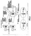
- FIG. 4 is a diagram showing an example of processing when a call origination request is made in the present explainatory example.
- the switching station 111 acquires subscriber service information about the mobile station 150 from the HLR 140 (in step S32) since the VLR 121 has no subscriber service information about the mobile station 150. Then the switching station 111 normally performs call origination connection processing (in S33).
- the arrangement may alternatively be such that in a case where a switching station cannot register subscriber service information in its own VLR, it registers the subscriber service information in the VLR of another switching station instead of acquiring the subscriber service information from the HLR 140.
- "Another switching station” may be an adjacent switching station, a switching station in whose coverage area the mobile station has been located, a switching station having a large capacity VLR, etc.
- a first candidate, a second candidate, and so on for "another switching station” may be determined in advance with respect to each switching station. When one switching station requests another switching station to register subscriber service information, the requested switching station registers the subscriber service information.
- Each switching station stores information that in which VLR the subscriber service information of the mobile station was stored, if it had subscriber service information registered by the another switching station in a situation where it could not register the subscriber service information of the mobile station in its own VLR. Thereby, the switching station can recognize the VLR in which the subscriber service information is stored, when call origination from the mobile station or call termination to the mobile station occurs later.
- FIG. 6 is a diagram showing an example of processing when a location registration request is made in the second explainatory example of the present invention.
- the switching station 111 receives a location registration signal from the mobile station 150 (in S51 of FIG. 6 ) and acquires (in S52) subscriber service information about the mobile station 150 from the switching station 112 in whose coverage area the mobile station 150 has been located.
- no subscriber service information can be newly registered in the VLR 121 (in S53).
- the switching station 111 registers subscriber location information about the mobile station 150 in the HLR 140 (in S54), as it stores corresponding information in the VLR 121 in the case where subscriber service information can be registered in the VLR 121. Further, the switching station 111 registers subscriber service information about the mobile station 150 in another switching station (in a VLR 123 of a switching station 113 in this example) (in S55), and normally completes location registration processing (in 856).
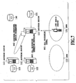
- the switching station When a call origination signal is transmitted from the mobile station to the switching station (in S61 of FIG. 7 ) after registration in the another VLR, the switching station acquires subscriber service information about the mobile station from the another VLR (in step S62) and performs call origination connection processing (in S63). When the switching station requests the another switching station to transmit the subscriber service information, the another switching station transmits the subscriber service information to the switching station.
- FIG. 8 is a diagram showing an example of processing when a call termination request is made in the present explainatory example.
- a method may be used in which a switching station deletes one of pieces of subscriber service information presently registered in its own VLR to enable registration of subscriber service information about a mobile station that has transmitted a location registration signal in its own VLR.
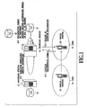
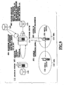
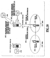
- FIG. 9 is a diagram showing an example of processing when a location registration request is made in the embodiment of the present invention.
- the switching station 111 receives a location registration signal from the mobile station 150 (in S81 of FIG. 9 ) and acquires (in S82) subscriber service information about the mobile station 150 from the switching station 112 in whose coverage area the mobile station 150 has been located. In this situation, no subscriber service information can be newly registered in the VLR 121.
- the switching station 111 deletes one of pieces of subscriber service information presently registered in the VLR 121 (assumed to be subscriber service information about a mobile station 151) and registers the subscriber service information about the mobile station 150 in the VLR 121 (in S83). The switching station 111 then registers subscriber location information about the mobile station 150 in the HLR 140 (in S84) , and normally completes location registration processing (in S85).
- the arrangement may be such that when one piece of subscriber service information presently registered in the VLR of the switching station is deleted, deletion from the VLR of the subscriber location information about the mobile station corresponding to the subscriber service information to be deleted is inhibited.
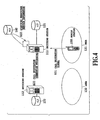
- FIG. 10 is a diagram showing an example of processing when a location registration request is made in the present embodiment.
- the switching station can acquire the subscriber location information about the mobile station from its own VLR (in S92), and register it in the HLR 140 (in S93). Then, the switching station normally completes location registration processing (in S94).
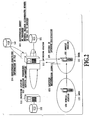
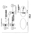
- FIG. 11 is a diagram showing an example of processing when a call origination request is made in the present embodiment.
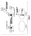
- FIG. 12 is a diagram showing an example of processing when a call termination request is made in the present embodiment.
- the mobile station whose subscriber service information is to be deleted can be selected in consideration of call origination, call termination, location registration, power state, etc. of mobile stations.
- FIG. 13 is a diagram for explaining attach state and detach state.
- a switching station makes the state of the mobile station attach state. Thereafter, the switching station finds, using a timer #2 (mobile not reachable timer), a mobile station which has made neither call origination, call termination nor location registration for predetermined period of time in the area of the switching station, and makes the state of the found mobile station detach state.
- the switching station also makes the state of a mobile station detach state, when it receives from the mobile station a detach signal indicating that the power has become off.
- the switching station makes the state of the mobile station attach state.
- a mobile station periodically (for example, every three hours) transmits, using a timer #1 (periodic routing update timer), a location registration signal to the switching station to request location registration.
- Attach state and detach state can be represented, for example, by using off and on of a (detach) flag.
- the mobile station whose subscriber service information is to be deleted can be selected in consideration of communication state of mobile stations.
- the communication is disconnected unconditionally. Therefore, as the mobile station whose subscriber service information is to be deleted, a mobile station which is not in communication can be selected. That is, when a switching station intends to select a mobile station as the mobile station whose subscriber service information is to be deleted, and if the mobile station is in communication, the switching station can select another mobile station as the mobile station whose subscriber service information is to be deleted.
- Communication state of each mobile station can be managed, for example, at VLR or a service control unit performing control regarding call processing and service to subscriber, by having management table of communication state.
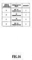
- FIG. 16 is a diagram for explaining an example of selecting a mobile station whose subscriber service information is to be deleted.
- the mobile stations A and D since the communication state of mobile stations A and D is not in communication and the state of mobile stations B and C is in communication, the mobile stations A and D have higher priority than the mobile stations B and C. That is, one of the mobile stations A and D is selected as the mobile station whose subscriber service information is to be deleted.
- the switching station registers, when it resisters subscriber service information, the subscriber service information as subscriber service information possible to be overwritten (subscriber service information possible to be deleted when the maximum number of accommodated users has been reached in VLR) or as subscriber service information impossible to be overwritten, and selects the subscriber service information to be overwritten from (pieces of) subscriber service information possible to be overwritten. For example, it is possible to register subscriber service information of a subscriber who frequently uses communication as subscriber service information impossible to be overwritten, and register subscriber service information of a subscriber who rarely uses communication as subscriber service information possible to be overwritten.
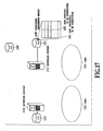
- FIG. 17 is a diagram showing an example of preparing an area possible to be overwritten and an area impossible to be overwritten in a subscriber management memory of VLR.
- the switching station 111 registers subscriber service information possible to be overwritten in an area 181 possible to be overwritten, and registers subscriber service information impossible to be overwritten in an area 182 impossible to be overwritten.
- the subscriber service information about a mobile station is acquired from a switching station in whose coverage area the mobile station has been located is described.
- the subscriber service information can be acquired from HLR when location registration other than the first location registration is made as well as when the first location registration is made.
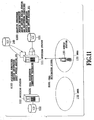
- FIG. 18 is a diagram showing an example of processing corresponding to the example of processing shown in FIG. 9 when a location registration request is made, in a case where subscriber service information is acquired from an HLR.
- the switching station 111 having the VLR 121 which has accepted the maximum number of subscribers receives a location registration signal from the mobile station 150 (in S111 of FIG. 18 )
- the switching station 111 registers subscriber location information about the mobile station 150 in the HLR 140, and receives subscriber service information about the mobile station 150 from the HLR 140 (in S112).
- the switching station 111 deletes one of pieces of subscriber service information presently registered in the VLR 121 and registers the subscriber service information about the mobile station 150 in the VLR 121 (in S113). In this way, location registration processing is normally completed (in S114).
- a subscriber can acquire service without dependence on the accommodation capacity of a management unit which manages subscriber information. That is, the system allows location registration, call origination and call termination processing for subscribers as an excess over the maximum number of accommodated subscribers, and more comfortable communication environment can be provided to subscribers by effectively using VLR memories.
Landscapes
- Engineering & Computer Science (AREA)
- Computer Networks & Wireless Communication (AREA)
- Signal Processing (AREA)
- Databases & Information Systems (AREA)
- Mobile Radio Communication Systems (AREA)
Description
- The present invention relates to a switching station, a subscriber location information registration method, a subscriber service information acquisition method, a subscriber service information registration method, and a subscriber service information transmission method.
- There are two methods for mobility control in mobile communication: an HLR (Home Location Register) method in which location information and service information of subscribers (users) are managed by an apparatus physically separated from a switching station; and a VLR (Visited Location Register) method in which subscriber location information and service information are managed by a VLR in a switching station.
- In the case of the VLR method, if the location of a user cannot be registered after the maximum number of accommodated users has been reached, neither of call origination and call termination by the user is allowed.
- In connection processing of location registration function, call origination function and call termination function of the VLR method, when a mobile station moves into an area covered by a switching station, the mobile station recognizes change of location area and transmits a location registration signal to the switching station.
- The switching station acquires subscriber service information about the mobile station from the switching station in whose coverage area the mobile station has been located (from the HLR at the time of the first location registration). Also, information on the location of the mobile station used at the time of call termination is registered in the HLR. When the mobile station makes a call origination, the switching station performs call origination processing by using subscriber service information from the VLR. At the time of call termination, call termination processing is performed by using the (subscriber) location information from the HLR.
-
FIG. 1 is a diagram showing an example of a conventional mobile communication system and an example of processing when a location registration request is made. Referring toFIG. 1 ,switching stations VLR - When a
mobile station 50 moves from an (service)area 32 of theswitching station 12 into anarea 31 of theswitching station 11 having theVLR 21 which has accepted the maximum number of subscribers, theswitching station 11 receives a location registration (request) signal from the mobile station 50 (in S11 ofFIG. 1 ) and acquires (in S12) subscriber service information about themobile station 50 from theswitching station 12 in whose coverage area themobile station 50 has been located. However, no subscriber service information can be newly registered in the VLR 21 (in S13). Therefore location registration processing ends in failure (in S14) and updating (registration) of subscriber location information in anHLR 40 is not performed. If the subscriber makes call origination in such a situation, call origination processing is not normally performed since theswitching station 11 has no service information about the subscriber on theVLR 21. Call termination processing also ends in failure since the subscriber location information in theHLR 40 has not been updated. - The number of subscribers (subscriber information items) possible to be registered in the VLR depends on hardware resources. Also, because the hardware resources are fixedly assigned, it is not possible to manage information on dynamically changing subscribers (users) with flexibility.
- From the patent publication
US-A-6078811 and the publication by LIN Y-B: "OVERFLOW CONTROL FOR CELLULAR MOBILITY DATABASE" there is known a scheme of mobile user registration overflow control for a portable communications network including one or more home location registers, one or more visitor location registers and one or more mobile terminal equipments. - Therefore an object of the present invention is to enable a subscriber to acquire service without dependence on the accommodation capacity of a management unit which manages subscriber information.
- In accordance with the first aspect of the present invention, there is provided a switching station as claimed in
claim 1. - In the second aspect of the present invention, there is provided a subscriber location information registration method as claimed in claim 13.
- According to the above mentioned aspects, a subscriber can acquire service without dependence on the accommodation capacity of a management unit which manages subscriber information.
- The above and other objects, effects, features and advantages of the present invention will become more apparent from the following description of embodiments thereof taken in conjunction with the accompanying drawings.
-
FIG. 1 is a diagram showing an example of a configuration of a conventional mobile communication system and an example of processing when a location registration request is made; -
FIG. 2 is a diagram showing an example of a configuration of a mobile communication system and an example of processing when a location registration request is made in the first explainatory example; -
FIG. 3 is a diagram showing an example of a configuration of a switching station; -
FIG. 4 is a diagram showing an example of processing when a call origination request is made in the first explainatory example; -
FIG. 5 is a diagram showing an example of processing when a call termination request is made in the first explainatory example; -
FIG. 6 is a diagram showing an example of processing when a location registration request is made in the second explainatory example; -
FIG. 7 is a diagram showing an example of processing when a call origination request is made in the second explainatory example; -
FIG. 8 is a diagram showing an example of processing when a call termination request is made in the second explainatory example; -
FIG. 9 is a diagram showing an example of processing when a location registration request is made in the embodiment of the present invention; -
FIG. 10 is a diagram showing an example of processing when a location registration request is made in the embodiment of the present invention; -
FIG. 11 is a diagram showing an example of processing when a call origination request is made in the embodiment of the present invention; -
FIG. 12 is a diagram showing an example of processing when a call termination request is made in the embodiment of the present invention; -
FIG. 13 is a diagram for explaining attach state and detach state; -
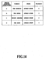
FIG. 14 is a diagram for explaining an example of selecting a mobile station whose subscriber service information is to be deleted; -
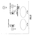
FIG. 15 is a diagram showing an example of inquiring communication state of a service control unit, when the service control unit manages the communication state; -
FIG. 16 is a diagram for explaining an example of selecting a mobile station whose subscriber service information is to be deleted; -
FIG. 17 is a diagram showing an example of preparing an area possible to be overwritten and an area impossible to be overwritten in a subscriber management memory of VLR; and -
FIG. 18 is a diagram showing an example of processing corresponding to the example of processing shown inFIG. 9 when a location registration request is made, in a case where subscriber service information is acquired from an HLR. - Embodiment of the present invention will be described in detail with reference to the accompanying drawings.
-
FIG. 2 is a diagram showing an example of a configuration of a mobile communication system and an example of processing when a location registration request is made in the first embodiment of the present invention. Referring toFIG. 2 ,switching stations VLRs VLRs switching stations VLRs HLR 140 is a management unit which is provided independently of switching stations, and which manages subscriber information. -
FIG. 3 is a diagram showing an example of a configuration of a switching station. Theswitching station 111 has acontrol portion 191 which performs various kinds of control, astorage portion 192 which stores various processing procedures, data, etc., and acommunication portion 193. A VLR 121 may be provided inside or outside theswitching station 111, as are those described above. Thecontrol portion 191 performs communication with other switching stations, mobile stations, HLRs, VLRs, etc., through thecommunication portion 193 and other switching stations, base stations or the like. The VLR 121 has asubscriber management memory 180 which stores subscriber information. Other switching stations (theswitching station 112 etc. ) can have the same configuration as theswitching station 111. - Referring again to
FIG. 2 , when amobile station 150 moves from anarea 132 of theswitching station 112 into anarea 131 of theswitching station 111 having theVLR 121 which has accepted the maximum number of subscribers, theswitching station 111 receives a location registration signal from the mobile station 150 (in S21 ofFIG. 2 ) and acquires (in S22) subscriber service information about themobile station 150 from theswitching station 112 in whose coverage area themobile station 150 has been located. Here, no subscriber service information can be newly registered in the VLR 121 (in S23). However, theswitching station 111 registers subscriber location information about themobile station 150 in the HLR 140 (in S24), as it stores corresponding information in theVLR 121 in the case where subscriber service information can be registered in theVLR 121. Theswitching station 111 normally completes location registration processing (in S25). Theswitching station 111 can store in thestorage portion 192 or theVLR 121, information of themobile station 150 as a mobile station whose subscriber service information is not registered in theVLR 121. Thereby, theswitching station 111 can recognize that subscriber service information of themobile station 150 is not registered in theVLR 121, when call origination from themobile station 150 or call termination to themobile station 150 occurs later. -
FIG. 4 is a diagram showing an example of processing when a call origination request is made in the present explainatory example. Thereafter, when a call origination signal is transmitted from themobile station 150 to the switching station 111 (in S31 ofFIG. 4 ), theswitching station 111 acquires subscriber service information about themobile station 150 from the HLR 140 (in step S32) since theVLR 121 has no subscriber service information about themobile station 150. Then theswitching station 111 normally performs call origination connection processing (in S33). -
FIG. 5 is a diagram showing an example of processing when a call termination request is made in the present explainatory example. When a call termination request is made to themobile station 150, call termination processing can also be performed normally since the subscriber location information about themobile station 150 has been correctly updated in theHLR 140. When a call termination signal to themobile station 150 is transmitted to the switching station 111 (in S41 ofFIG. 5 ), the switchingstation 111 acquires the subscriber service information about themobile station 150 from the HLR 140 (in S42) and performs call termination processing (in S43). - The arrangement may alternatively be such that in a case where a switching station cannot register subscriber service information in its own VLR, it registers the subscriber service information in the VLR of another switching station instead of acquiring the subscriber service information from the
HLR 140. "Another switching station" may be an adjacent switching station, a switching station in whose coverage area the mobile station has been located, a switching station having a large capacity VLR, etc. A first candidate, a second candidate, and so on for "another switching station" may be determined in advance with respect to each switching station. When one switching station requests another switching station to register subscriber service information, the requested switching station registers the subscriber service information. Each switching station stores information that in which VLR the subscriber service information of the mobile station was stored, if it had subscriber service information registered by the another switching station in a situation where it could not register the subscriber service information of the mobile station in its own VLR. Thereby, the switching station can recognize the VLR in which the subscriber service information is stored, when call origination from the mobile station or call termination to the mobile station occurs later. -
FIG. 6 is a diagram showing an example of processing when a location registration request is made in the second explainatory example of the present invention. When themobile station 150 moves from thearea 132 of the switchingstation 112 into thearea 131 of the switchingstation 111 having theVLR 121 which has accepted the maximum number of subscribers, the switchingstation 111 receives a location registration signal from the mobile station 150 (in S51 ofFIG. 6 ) and acquires (in S52) subscriber service information about themobile station 150 from the switchingstation 112 in whose coverage area themobile station 150 has been located. Here, no subscriber service information can be newly registered in the VLR 121 (in S53). However, the switchingstation 111 registers subscriber location information about themobile station 150 in the HLR 140 (in S54), as it stores corresponding information in theVLR 121 in the case where subscriber service information can be registered in theVLR 121. Further, the switchingstation 111 registers subscriber service information about themobile station 150 in another switching station (in aVLR 123 of a switchingstation 113 in this example) (in S55), and normally completes location registration processing (in 856). -
FIG. 7 is a diagram showing an example of processing when a call origination request is made in the present explainatory example. - When a call origination signal is transmitted from the mobile station to the switching station (in S61 of
FIG. 7 ) after registration in the another VLR, the switching station acquires subscriber service information about the mobile station from the another VLR (in step S62) and performs call origination connection processing (in S63). When the switching station requests the another switching station to transmit the subscriber service information, the another switching station transmits the subscriber service information to the switching station. -
FIG. 8 is a diagram showing an example of processing when a call termination request is made in the present explainatory example. - When a call termination signal is transmitted to the mobile station (in S71 of
FIG. 8 ) after registration in the another switching station, the switching station acquires the subscriber service information about the mobile station from the another switching station (in S72) and performs call termination processing (in S73). When the switching station requests the another switching station to transmit the subscriber service information, the another switching station transmits the subscriber service information to the switching station. - As an alternative to the method of using the method of acquiring subscriber service information from the
HLR 140 or the method of registering subscriber service information in another switching station, a method may be used in which a switching station deletes one of pieces of subscriber service information presently registered in its own VLR to enable registration of subscriber service information about a mobile station that has transmitted a location registration signal in its own VLR. -
FIG. 9 is a diagram showing an example of processing when a location registration request is made in the embodiment of the present invention. When themobile station 150 moves from thearea 132 of the switchingstation 112 into thearea 131 of the switchingstation 111 having theVLR 121 which has accepted the maximum number of subscribers, the switchingstation 111 receives a location registration signal from the mobile station 150 (in S81 ofFIG. 9 ) and acquires (in S82) subscriber service information about themobile station 150 from the switchingstation 112 in whose coverage area themobile station 150 has been located. In this situation, no subscriber service information can be newly registered in theVLR 121. However, the switchingstation 111 deletes one of pieces of subscriber service information presently registered in the VLR 121 (assumed to be subscriber service information about a mobile station 151) and registers the subscriber service information about themobile station 150 in the VLR 121 (in S83). The switchingstation 111 then registers subscriber location information about themobile station 150 in the HLR 140 (in S84) , and normally completes location registration processing (in S85). - The arrangement may be such that when one piece of subscriber service information presently registered in the VLR of the switching station is deleted, deletion from the VLR of the subscriber location information about the mobile station corresponding to the subscriber service information to be deleted is inhibited.
-
FIG. 10 is a diagram showing an example of processing when a location registration request is made in the present embodiment. - Thereafter, when a location registration signal is received from the mobile station whose subscriber service information has been deleted (in S91 of
FIG. 10 ), the switching station can acquire the subscriber location information about the mobile station from its own VLR (in S92), and register it in the HLR 140 (in S93). Then, the switching station normally completes location registration processing (in S94). -
FIG. 11 is a diagram showing an example of processing when a call origination request is made in the present embodiment. - In a case where the switching station receives a call origination signal from the mobile station whose subscriber service information has been deleted (in S101 of
FIG. 11 ), the switching station acquires the subscriber service information about the mobile station from the HLR 140 (in S102). If the switching station cannot newly register the acquired subscriber service information in its own VLR, it may delete one of pieces of subscriber service information presently registered in its own VLR and register the acquired subscriber service information in its own VLR (in S103). Then the switching station performs call origination connection processing (in S104). -
FIG. 12 is a diagram showing an example of processing when a call termination request is made in the present embodiment. - In a case where the switching station receives a call termination signal to the mobile station whose subscriber service information has been deleted (in S121 of
FIG. 12 ), the switching station acquires the subscriber service information about the mobile station from the HLR 140 (in S122). If the switching station cannot newly register the acquired subscriber service information in its own VLR, it may delete one of pieces of subscriber service information presently registered in its own VLR and register the acquired subscriber service information in its own VLR (in S123). Then the switching station performs call termination processing (in S124). - In the steps S83 S103 and S123, the mobile station whose subscriber service information is to be deleted can be selected in consideration of call origination, call termination, location registration, power state, etc. of mobile stations.
- For example, as the mobile station whose subscriber service information is to be deleted, a mobile station which has made neither call origination nor call termination during the longest time period till the present time can be selected.
- Also, for example, as the mobile station whose subscriber service information is to be deleted, a mobile station in detach state, i.e. , a mobile station which has made neither call origination, call termination nor location registration for predetermined period of time, or a mobile station whose power state is off can be selected.
- The second example will be described in detail.
-
FIG. 13 is a diagram for explaining attach state and detach state. When location registration is performed for a mobile station, a switching station makes the state of the mobile station attach state. Thereafter, the switching station finds, using a timer #2 (mobile not reachable timer), a mobile station which has made neither call origination, call termination nor location registration for predetermined period of time in the area of the switching station, and makes the state of the found mobile station detach state. The switching station also makes the state of a mobile station detach state, when it receives from the mobile station a detach signal indicating that the power has become off. When a mobile station whose state is detach state makes call origination, call termination or location registration, the switching station makes the state of the mobile station attach state. A mobile station periodically (for example, every three hours) transmits, using a timer #1 (periodic routing update timer), a location registration signal to the switching station to request location registration. Attach state and detach state can be represented, for example, by using off and on of a (detach) flag. -
FIG. 14 is a diagram for explaining an example of selecting a mobile station whose subscriber service information is to be deleted. InFIG. 14 , thetimer # 2 column shows, for each mobile station (subscriber), elapsed time since the last time the mobile station made call origination, call termination or location registration. The priority ofFIG. 14 is priority (rank) for each mobile station to be selected as the mobile station whose subscriber service information is to be deleted. In the example ofFIG. 14 , since the state of mobile stations A and B is attach state and the state of mobile stations C and D is detach state, the mobile stations C and D have higher priority than the mobile stations A and B. Between mobile stations having the same state, a mobile station having longer elapsed time has higher priority. Therefore, the mobile station D has higher priority than the mobile station C, and the mobile station B has higher priority than the mobile station A. - The mobile station whose subscriber service information is to be deleted can be selected in consideration of communication state of mobile stations. In general, when subscriber service information is deleted, and if the mobile station corresponding to the deleted subscriber service information is in communication, the communication is disconnected unconditionally. Therefore, as the mobile station whose subscriber service information is to be deleted, a mobile station which is not in communication can be selected. That is, when a switching station intends to select a mobile station as the mobile station whose subscriber service information is to be deleted, and if the mobile station is in communication, the switching station can select another mobile station as the mobile station whose subscriber service information is to be deleted. Communication state of each mobile station can be managed, for example, at VLR or a service control unit performing control regarding call processing and service to subscriber, by having management table of communication state.
-
FIG. 15 is a diagram showing an example of inquiring communication state of a service control unit, when the service control unit manages the communication state. In this embodiment, a service control unit is provided for each switching station. The switchingstation 111 inquires communication state of each mobile station of aservice control unit 161, receives its response from theservice control unit 161, and selects in consideration of the response, the mobile station whose subscriber service information is to be deleted. -
FIG. 16 is a diagram for explaining an example of selecting a mobile station whose subscriber service information is to be deleted. In the example ofFIG. 16 , since the communication state of mobile stations A and D is not in communication and the state of mobile stations B and C is in communication, the mobile stations A and D have higher priority than the mobile stations B and C. That is, one of the mobile stations A and D is selected as the mobile station whose subscriber service information is to be deleted. - The switching station registers, when it resisters subscriber service information, the subscriber service information as subscriber service information possible to be overwritten (subscriber service information possible to be deleted when the maximum number of accommodated users has been reached in VLR) or as subscriber service information impossible to be overwritten, and selects the subscriber service information to be overwritten from (pieces of) subscriber service information possible to be overwritten. For example, it is possible to register subscriber service information of a subscriber who frequently uses communication as subscriber service information impossible to be overwritten, and register subscriber service information of a subscriber who rarely uses communication as subscriber service information possible to be overwritten.
-
FIG. 17 is a diagram showing an example of preparing an area possible to be overwritten and an area impossible to be overwritten in a subscriber management memory of VLR. The switchingstation 111 registers subscriber service information possible to be overwritten in anarea 181 possible to be overwritten, and registers subscriber service information impossible to be overwritten in anarea 182 impossible to be overwritten. - In the foregoing description, a case where subscriber service information about a mobile station is acquired from a switching station in whose coverage area the mobile station has been located is described. However, the subscriber service information can be acquired from HLR when location registration other than the first location registration is made as well as when the first location registration is made.
-
FIG. 18 is a diagram showing an example of processing corresponding to the example of processing shown inFIG. 9 when a location registration request is made, in a case where subscriber service information is acquired from an HLR. When the switchingstation 111 having theVLR 121 which has accepted the maximum number of subscribers receives a location registration signal from the mobile station 150 (in S111 ofFIG. 18 ), the switchingstation 111 registers subscriber location information about themobile station 150 in theHLR 140, and receives subscriber service information about themobile station 150 from the HLR 140 (in S112). Then, the switchingstation 111 deletes one of pieces of subscriber service information presently registered in theVLR 121 and registers the subscriber service information about themobile station 150 in the VLR 121 (in S113). In this way, location registration processing is normally completed (in S114). - According to the present invention, as described above, a subscriber can acquire service without dependence on the accommodation capacity of a management unit which manages subscriber information. That is, the system allows location registration, call origination and call termination processing for subscribers as an excess over the maximum number of accommodated subscribers, and more comfortable communication environment can be provided to subscribers by effectively using VLR memories.
- The present invention has been described in detail with respect to preferred embodiment, and it will now be apparent from the foregoing to those skilled in the art that changes and modifications may be made without departing from the invention in its broader aspects, and it is the intention, therefore, in the appended claims to cover all such changes and modifications as fall within the scope of the invention.
Claims (13)
- A switching station (111) characterized by comprising:means for receiving a location registration signal (S81) from a mobile station (150);means for deleting (S83), when the location registration signal (S81) is received, one of pieces of subscriber service information presently registered in a first management unit (121) provided for use with the switching station for (111) managing subscriber information, the means for deleting further adapted to register (S83) subscriber service information of the mobile station (150) that has transmitted the location registration signal in the first management unit if no subscriber service information can be newly registered in the first management unit; characterised by
means for acquiring (S102), when a call origination signal (S101) is received from another mobile station (151) not presently registered in the first management unit, subscriber service information(102) about the another mobile station (151) from another management unit (140) that manages the subscriber service information of the another mobile station (151). - The switching station as claimed in claim 1, characterized by further comprising
means for registering subscriber location information about a mobile station in a second management unit managing subscriber information, and
means for receiving subscriber service information about the mobile station from said second management unit,
wherein said switching station is adapted to register, when the location registration signal is received, subscriber location information about the mobile station that has transmitted the location registration signal in the second management unit, to receive subscriber service information about the mobile station that has transmitted the location registration signal from said second management unit, to delete one of pieces of subscriber service information presently registered in the first management unit, and to register the subscriber service information of the mobile station that has transmitted the location registration signal in the first management unit, if no subscriber service information can be newly registered in the first management unit. - The switching station as claimed in claim 1, characterized by further comprising
means for registering subscriber location information about a mobile station in a second management unit managing subscriber information,
wherein when the switching station deletes one of pieces of subscriber service information presently registered in the first management unit, the switching station is adapted to not delete, from the first management unit, subscriber location information about a mobile station corresponding to the deleted subscriber service information, and
wherein when the switching station receives the location registration signal from the mobile station corresponding to the deleted subscriber service information, the switching station is adapted to register in the second management unit the subscriber location information about the mobile station registered in the first management unit. - The switching station as claimed in claim 1, characterized in that when the switching station receives, after deleting one of pieces of subscriber service information presently registered in the first management unit for use with the switching station, a call origination signal from a mobile station corresponding to the deleted subscriber service information, the switching station is adapted to acquire the deleted subscriber service information about the mobile station from a second management unit, and, if the acquired subscriber service information cannot be newly registered in the first management unit, the switching station is adapted to delete one of pieces of subscriber service information presently registered in the first management unit, and registers the acquired subscriber service information in the first management unit.
- The switching station as claimed in claim 1, characterized by further comprising
means for receiving a call termination signal to a mobile station, and
means for acquiring subscriber service information about a mobile station from a second management unit managing subscriber information,
wherein when the switching station receives, after deleting one of pieces of subscriber service information presently registered in the first management unit, a call termination signal to a mobile station corresponding to the deleted subscriber service information, the switching station is adapted to acquire the deleted subscriber service information about the mobile station from the second management unit, and, if the acquired subscriber service information cannot be newly registered in the first management unit, the switching station is adapted to delete one of pieces of subscriber service information presently registered in the first management unit, and to register the acquired subscriber service information in the first management unit. - The switching station as claimed in any one of claims 2 to 5, characterized in that said second management unit is an HLR.
- The switching station as claimed in claim 1, characterized in that said first management unit is a VLR.
- The switching station as claimed in claim 1, characterized in that said switching station is adapted to select the mobile station whose subscriber service information is to be deleted, in consideration of at least one of call origination, call termination, location registration, and power state of mobile stations.
- The switching station as claimed in claim 8, characterized in that said switching station is adapted to select, as the mobile station whose subscriber service information is to be deleted, a mobile station which has made neither call origination nor call termination during the longest time period till the present time.
- The switching station as claimed in claim 8, characterized in that said switching station is adapted to select, as the mobile station whose subscriber service information is to be deleted, a mobile station which has made neither call origination, call termination nor location registration for predetermined period of time, or a mobile station whose power state is off.
- The switching station as claimed in claim 1, characterized in that said switching station is adapted to select the mobile station whose subscriber service information is to be deleted, in consideration of communication state of mobile stations.
- The switching station as claimed in claim 1, characterized in that said switching station is adapted to register, when it registers subscriber service information, the subscriber service information as first type of subscriber service information or as second type of subscriber service information, and is adapted to select the subscriber service information to be
deleted from said first type of subscriber service information. - A subscriber service information registration method characterized by comprising the steps of:receiving, at a switching station (111), a location registration signal (S84) from a mobile station (150);deleting (S83), at the switching station (111), when the location registration signal (S81) is received, one of pieces of subscriber service information presently registered in a first management unit (121) provided for use with the switching station (111) and managing subscriber information, and registering (S83), at the switching station (111), subscriber service information of the mobile station (150) that has transmitted the location registration signal in the first management unit, if no subscriber service information can be newly registered in the first management unit;characterised by
acquiring (S102), when a call origination signal (S101) is received from another mobile station (151) not presently registered in the first management unit, subscriber service information (102) about the another mobile station (151) from an other management unit (140) that manages the subscriber service information of the another mobile station (151).
Applications Claiming Priority (3)
| Application Number | Priority Date | Filing Date | Title |
|---|---|---|---|
| JP2001031467 | 2001-02-07 | ||
| JP2001031467 | 2001-02-07 | ||
| EP02250831A EP1233640A3 (en) | 2001-02-07 | 2002-02-07 | Method for avoiding database overflow in a visitor location register (VLR) |
Related Parent Applications (2)
| Application Number | Title | Priority Date | Filing Date |
|---|---|---|---|
| EP02250831.1 Division | 2002-02-07 | ||
| EP02250831A Division EP1233640A3 (en) | 2001-02-07 | 2002-02-07 | Method for avoiding database overflow in a visitor location register (VLR) |
Publications (3)
| Publication Number | Publication Date |
|---|---|
| EP1545147A2 EP1545147A2 (en) | 2005-06-22 |
| EP1545147A3 EP1545147A3 (en) | 2005-07-06 |
| EP1545147B1 true EP1545147B1 (en) | 2012-05-30 |
Family
ID=18895547
Family Applications (3)
| Application Number | Title | Priority Date | Filing Date |
|---|---|---|---|
| EP02250831A Withdrawn EP1233640A3 (en) | 2001-02-07 | 2002-02-07 | Method for avoiding database overflow in a visitor location register (VLR) |
| EP04077919A Expired - Lifetime EP1511348B1 (en) | 2001-02-07 | 2002-02-07 | Method for avoiding database overflow in a visitor location register (VLR) |
| EP04077920A Expired - Lifetime EP1545147B1 (en) | 2001-02-07 | 2002-02-07 | Method for avoiding database overflow in a visitor location register (VLR) |
Family Applications Before (2)
| Application Number | Title | Priority Date | Filing Date |
|---|---|---|---|
| EP02250831A Withdrawn EP1233640A3 (en) | 2001-02-07 | 2002-02-07 | Method for avoiding database overflow in a visitor location register (VLR) |
| EP04077919A Expired - Lifetime EP1511348B1 (en) | 2001-02-07 | 2002-02-07 | Method for avoiding database overflow in a visitor location register (VLR) |
Country Status (7)
| Country | Link |
|---|---|
| US (4) | US7016677B2 (en) |
| EP (3) | EP1233640A3 (en) |
| KR (1) | KR100455701B1 (en) |
| CN (1) | CN100379298C (en) |
| AU (1) | AU770748B2 (en) |
| CA (1) | CA2371010C (en) |
| SG (3) | SG120057A1 (en) |
Families Citing this family (15)
| Publication number | Priority date | Publication date | Assignee | Title |
|---|---|---|---|---|
| JP2003319442A (en) * | 2002-04-25 | 2003-11-07 | Nec Corp | Mobile communication system |
| US7496102B2 (en) * | 2002-06-07 | 2009-02-24 | At&T Corp. | Broadband telecommunication service with personalized service capability for mobile terminals |
| US7792053B1 (en) | 2002-07-08 | 2010-09-07 | At&T Intellectual Property Ii, L.P. | System for accessing end-to-end broadband network via network access server platform |
| EP1580925B1 (en) * | 2002-12-12 | 2008-02-06 | Huawei Technologies Co., Ltd. | Method for establishing or cancelling a service connection between a wireless local area network and a user terminal |
| FR2852476A1 (en) * | 2003-03-11 | 2004-09-17 | France Telecom | METHOD AND SYSTEM FOR MONITORING MOBILE TELEPHONES |
| US20060003762A1 (en) * | 2004-06-22 | 2006-01-05 | General Motors Corporation | Method and system for telematically deactivating satellite radio systems |
| JP4268605B2 (en) * | 2005-09-07 | 2009-05-27 | パナソニック株式会社 | Wireless communication apparatus and communication control method |
| CN100415052C (en) * | 2005-09-19 | 2008-08-27 | 华为技术有限公司 | Method for solving mobile station called problem |
| JP4955490B2 (en) * | 2007-09-12 | 2012-06-20 | 株式会社エヌ・ティ・ティ・ドコモ | Mobile communication system, local subscriber information management apparatus, and communication information management method |
| KR101007353B1 (en) * | 2008-12-03 | 2011-01-13 | 주식회사 케이티 | Mobile communication system and method for call setup |
| EP2399412B1 (en) | 2009-02-19 | 2015-09-16 | Telefonaktiebolaget L M Ericsson (publ) | Traffic control for roaming subscribers |
| CN102065519A (en) * | 2009-11-11 | 2011-05-18 | 中国移动通信集团公司 | Data storage equipment, network subsystem and call control method |
| US9301182B2 (en) * | 2010-11-02 | 2016-03-29 | Lg Electronics Inc. | Method and apparatus for reporting measurement result in wireless communication system |
| JP5670962B2 (en) * | 2012-06-15 | 2015-02-18 | 株式会社Nttドコモ | Mobile communication control device, mobile communication system, mobile communication control method, mobile communication control program |
| CN117979300B (en) * | 2024-04-02 | 2024-07-30 | 中国信息通信研究院 | Abnormal network registration behavior analysis method and device |
Family Cites Families (13)
| Publication number | Priority date | Publication date | Assignee | Title |
|---|---|---|---|---|
| US5097951A (en) * | 1990-10-16 | 1992-03-24 | Nucon Corporation | Unit load assembly for spools |
| US6078811A (en) * | 1997-08-04 | 2000-06-20 | Industrial Technology Research Institute | Mobile user registration overflow control for portable communications network |
| US6097951A (en) * | 1997-08-06 | 2000-08-01 | Northern Telecom Limited | Method and apparatus for wireless network architecture based on subscriber distribution |
| US6253081B1 (en) * | 1998-08-12 | 2001-06-26 | Bellsouth Intellect Pty Corp | Method and system for providing roaming service in a telecommunications system that is partially enabled for local number portability |
| JP3584747B2 (en) | 1998-09-10 | 2004-11-04 | 富士通株式会社 | Call control device and method |
| JP2000138960A (en) | 1998-10-30 | 2000-05-16 | Fujitsu Ltd | Mobile communication system and subscriber data management method |
| EP1011274A1 (en) * | 1998-12-16 | 2000-06-21 | TELEFONAKTIEBOLAGET L M ERICSSON (publ) | Method and service providing means for providing services in a telecommunication network |
| JP3286939B2 (en) * | 1998-12-17 | 2002-05-27 | 富士通株式会社 | Method and apparatus for controlling subscriber data accommodation of mobile station in mobile communication system |
| KR100365784B1 (en) * | 1999-03-22 | 2002-12-26 | 삼성전자 주식회사 | Method for implementing different charging rate in cellular system |
| EP1065904A1 (en) * | 1999-06-29 | 2001-01-03 | Alcatel | Location registration system for a mobile communications system |
| JP2001086546A (en) * | 1999-08-23 | 2001-03-30 | Swisscom Ag | Signal transmitting method for electric communication network and converting device |
| TW530507B (en) * | 2000-05-05 | 2003-05-01 | Ind Tech Res Inst | VoIP mobility in IP/cellular networks interworking |
| US6804540B1 (en) * | 2000-08-02 | 2004-10-12 | Ericsson Inc. | Remote band-pass filter in a distributed antenna system |
-
2002
- 2002-02-06 CA CA2371010A patent/CA2371010C/en not_active Expired - Fee Related
- 2002-02-07 EP EP02250831A patent/EP1233640A3/en not_active Withdrawn
- 2002-02-07 EP EP04077919A patent/EP1511348B1/en not_active Expired - Lifetime
- 2002-02-07 SG SG200200738A patent/SG120057A1/en unknown
- 2002-02-07 KR KR10-2002-0006945A patent/KR100455701B1/en not_active IP Right Cessation
- 2002-02-07 SG SG200508436-3A patent/SG131817A1/en unknown
- 2002-02-07 CN CNB021008868A patent/CN100379298C/en not_active Expired - Fee Related
- 2002-02-07 EP EP04077920A patent/EP1545147B1/en not_active Expired - Lifetime
- 2002-02-07 SG SG200508432-2A patent/SG131816A1/en unknown
- 2002-02-07 US US10/071,933 patent/US7016677B2/en not_active Expired - Fee Related
- 2002-02-07 AU AU15503/02A patent/AU770748B2/en not_active Ceased
-
2006
- 2006-02-02 US US11/346,023 patent/US20060128378A1/en not_active Abandoned
- 2006-02-02 US US11/345,793 patent/US20060142065A1/en not_active Abandoned
- 2006-02-02 US US11/346,116 patent/US20060128379A1/en not_active Abandoned
Also Published As
| Publication number | Publication date |
|---|---|
| US20060128379A1 (en) | 2006-06-15 |
| KR20020065860A (en) | 2002-08-14 |
| SG131816A1 (en) | 2007-05-28 |
| US7016677B2 (en) | 2006-03-21 |
| SG120057A1 (en) | 2006-03-28 |
| EP1511348B1 (en) | 2012-06-20 |
| CN1370019A (en) | 2002-09-18 |
| EP1511348A2 (en) | 2005-03-02 |
| EP1233640A3 (en) | 2002-10-30 |
| EP1233640A2 (en) | 2002-08-21 |
| KR100455701B1 (en) | 2004-11-06 |
| EP1545147A3 (en) | 2005-07-06 |
| AU1550302A (en) | 2002-08-08 |
| SG131817A1 (en) | 2007-05-28 |
| AU770748B2 (en) | 2004-03-04 |
| CA2371010C (en) | 2010-06-22 |
| EP1545147A2 (en) | 2005-06-22 |
| US20020123346A1 (en) | 2002-09-05 |
| US20060142065A1 (en) | 2006-06-29 |
| CA2371010A1 (en) | 2002-08-07 |
| CN100379298C (en) | 2008-04-02 |
| US20060128378A1 (en) | 2006-06-15 |
| EP1511348A3 (en) | 2005-03-16 |
Similar Documents
| Publication | Publication Date | Title |
|---|---|---|
| US20060128378A1 (en) | Switching station, subscriber location information registration method, subscriber service information acquisition method, subscriber service information registration method, and subscriber service information transmission method | |
| JP4024855B2 (en) | Communication system architecture and delivery method therefor | |
| EP0888025B1 (en) | Method and apparatus for providing partitioned telecommunication service | |
| JP2853688B2 (en) | Mobility management method for personal communication system | |
| US7480507B2 (en) | Mobile communication terminal, mobile communication system, and roaming connection method | |
| WO2005002248A1 (en) | Location assisted communications mode switching | |
| EP1740004A1 (en) | Mobile communication system | |
| CN110138580A (en) | A kind of update method and network side equipment of PDU session | |
| MXPA97006518A (en) | Wireless shared service system for inquili | |
| CN101472266B (en) | Method, equipment and system for updating mobile terminal position | |
| CA2476345C (en) | Switching station, subscriber location information registration method, subscriber service information acquisition method, subscriber service information registration method, and subscriber service information transmission method | |
| JP3735075B2 (en) | Exchange, subscriber location information registration method, subscriber service information acquisition method, subscriber service information registration method, and subscriber service information transmission method | |
| US6081712A (en) | Method and system for transmitting messages between devices of a mobile radiotelephone network | |
| JP4215129B2 (en) | Exchange, subscriber location information registration method, subscriber service information acquisition method, subscriber service information registration method, and subscriber service information transmission method | |
| EP2037704B1 (en) | Mobile communication system, local subscriber information management device, and communication information management method | |
| JP4579210B2 (en) | Location management method, location management device, and wireless terminal | |
| US20240259922A1 (en) | Electronic device | |
| JP2897174B2 (en) | Mobile subscriber data access method | |
| KR100810248B1 (en) | Method for providing position information of a mobile communication terminal equipment in a mobile communication system | |
| JP2865120B2 (en) | Mobile subscriber data access method | |
| MXPA98005150A (en) | Method and apparatus for providing dividi telecommunication services |
Legal Events
| Date | Code | Title | Description |
|---|---|---|---|
| PUAI | Public reference made under article 153(3) epc to a published international application that has entered the european phase |
Free format text: ORIGINAL CODE: 0009012 |
|
| PUAL | Search report despatched |
Free format text: ORIGINAL CODE: 0009013 |
|
| AC | Divisional application: reference to earlier application |
Ref document number: 1233640 Country of ref document: EP Kind code of ref document: P |
|
| AK | Designated contracting states |
Kind code of ref document: A2 Designated state(s): DE FR GB IT |
|
| AK | Designated contracting states |
Kind code of ref document: A3 Designated state(s): DE FR GB IT |
|
| 17P | Request for examination filed |
Effective date: 20051017 |
|
| AKX | Designation fees paid |
Designated state(s): DE FR GB IT |
|
| 17Q | First examination report despatched |
Effective date: 20080111 |
|
| RIC1 | Information provided on ipc code assigned before grant |
Ipc: H04W 28/08 20090101ALN20110823BHEP Ipc: H04W 8/04 20090101ALN20110823BHEP Ipc: H04W 8/12 20090101ALN20110823BHEP Ipc: H04W 8/06 20090101AFI20110823BHEP |
|
| RIC1 | Information provided on ipc code assigned before grant |
Ipc: H04W 8/06 20090101AFI20110901BHEP Ipc: H04W 28/08 20090101ALN20110901BHEP Ipc: H04W 8/04 20090101ALN20110901BHEP Ipc: H04W 8/12 20090101ALN20110901BHEP |
|
| RIC1 | Information provided on ipc code assigned before grant |
Ipc: H04W 8/04 20090101ALN20110916BHEP Ipc: H04W 8/12 20090101ALN20110916BHEP Ipc: H04W 28/08 20090101ALN20110916BHEP Ipc: H04W 8/06 20090101AFI20110916BHEP |
|
| REG | Reference to a national code |
Ref country code: DE Ref legal event code: R079 Ref document number: 60243074 Country of ref document: DE Free format text: PREVIOUS MAIN CLASS: H04Q0007380000 Ipc: H04W0008060000 |
|
| GRAP | Despatch of communication of intention to grant a patent |
Free format text: ORIGINAL CODE: EPIDOSNIGR1 |
|
| RIC1 | Information provided on ipc code assigned before grant |
Ipc: H04W 28/08 20090101ALN20111208BHEP Ipc: H04W 8/04 20090101ALN20111208BHEP Ipc: H04W 8/12 20090101ALN20111208BHEP Ipc: H04W 8/06 20090101AFI20111208BHEP |
|
| GRAS | Grant fee paid |
Free format text: ORIGINAL CODE: EPIDOSNIGR3 |
|
| GRAA | (expected) grant |
Free format text: ORIGINAL CODE: 0009210 |
|
| RAP1 | Party data changed (applicant data changed or rights of an application transferred) |
Owner name: NTT DOCOMO, INC. |
|
| AC | Divisional application: reference to earlier application |
Ref document number: 1233640 Country of ref document: EP Kind code of ref document: P |
|
| AK | Designated contracting states |
Kind code of ref document: B1 Designated state(s): DE FR GB IT |
|
| REG | Reference to a national code |
Ref country code: GB Ref legal event code: FG4D |
|
| REG | Reference to a national code |
Ref country code: DE Ref legal event code: R096 Ref document number: 60243074 Country of ref document: DE Effective date: 20120726 |
|
| PLBE | No opposition filed within time limit |
Free format text: ORIGINAL CODE: 0009261 |
|
| STAA | Information on the status of an ep patent application or granted ep patent |
Free format text: STATUS: NO OPPOSITION FILED WITHIN TIME LIMIT |
|
| PGFP | Annual fee paid to national office [announced via postgrant information from national office to epo] |
Ref country code: GB Payment date: 20130207 Year of fee payment: 12 Ref country code: FR Payment date: 20130301 Year of fee payment: 12 Ref country code: DE Payment date: 20130131 Year of fee payment: 12 |
|
| 26N | No opposition filed |
Effective date: 20130301 |
|
| REG | Reference to a national code |
Ref country code: DE Ref legal event code: R097 Ref document number: 60243074 Country of ref document: DE Effective date: 20130301 |
|
| REG | Reference to a national code |
Ref country code: DE Ref legal event code: R119 Ref document number: 60243074 Country of ref document: DE |
|
| GBPC | Gb: european patent ceased through non-payment of renewal fee |
Effective date: 20140207 |
|
| REG | Reference to a national code |
Ref country code: FR Ref legal event code: ST Effective date: 20141031 |
|
| REG | Reference to a national code |
Ref country code: DE Ref legal event code: R119 Ref document number: 60243074 Country of ref document: DE Effective date: 20140902 |
|
| PG25 | Lapsed in a contracting state [announced via postgrant information from national office to epo] |
Ref country code: FR Free format text: LAPSE BECAUSE OF NON-PAYMENT OF DUE FEES Effective date: 20140228 Ref country code: GB Free format text: LAPSE BECAUSE OF NON-PAYMENT OF DUE FEES Effective date: 20140207 Ref country code: DE Free format text: LAPSE BECAUSE OF NON-PAYMENT OF DUE FEES Effective date: 20140902 |
|
| PG25 | Lapsed in a contracting state [announced via postgrant information from national office to epo] |
Ref country code: IT Free format text: LAPSE BECAUSE OF NON-PAYMENT OF DUE FEES Effective date: 20140207 |