EP1544978A2 - Axial gap motor - Google Patents
Axial gap motor Download PDFInfo
- Publication number
- EP1544978A2 EP1544978A2 EP04028377A EP04028377A EP1544978A2 EP 1544978 A2 EP1544978 A2 EP 1544978A2 EP 04028377 A EP04028377 A EP 04028377A EP 04028377 A EP04028377 A EP 04028377A EP 1544978 A2 EP1544978 A2 EP 1544978A2
- Authority
- EP
- European Patent Office
- Prior art keywords
- rotor
- rotor shaft
- magnets
- stator
- axis
- Prior art date
- Legal status (The legal status is an assumption and is not a legal conclusion. Google has not performed a legal analysis and makes no representation as to the accuracy of the status listed.)
- Granted
Links
Images


Classifications
-
- H—ELECTRICITY
- H02—GENERATION; CONVERSION OR DISTRIBUTION OF ELECTRIC POWER
- H02K—DYNAMO-ELECTRIC MACHINES
- H02K1/00—Details of the magnetic circuit
- H02K1/06—Details of the magnetic circuit characterised by the shape, form or construction
- H02K1/22—Rotating parts of the magnetic circuit
- H02K1/27—Rotor cores with permanent magnets
- H02K1/2793—Rotors axially facing stators
- H02K1/2795—Rotors axially facing stators the rotor consisting of two or more circumferentially positioned magnets
- H02K1/2796—Rotors axially facing stators the rotor consisting of two or more circumferentially positioned magnets where both axial sides of the rotor face a stator
-
- H—ELECTRICITY
- H02—GENERATION; CONVERSION OR DISTRIBUTION OF ELECTRIC POWER
- H02K—DYNAMO-ELECTRIC MACHINES
- H02K21/00—Synchronous motors having permanent magnets; Synchronous generators having permanent magnets
- H02K21/12—Synchronous motors having permanent magnets; Synchronous generators having permanent magnets with stationary armatures and rotating magnets
- H02K21/24—Synchronous motors having permanent magnets; Synchronous generators having permanent magnets with stationary armatures and rotating magnets with magnets axially facing the armatures, e.g. hub-type cycle dynamos
Definitions
- the present invention relates in general to electric motors and motor particularly to the motors of an axial gap type, which comprises a rotor shaft that is rotatable about its axis, at least one rotor that is fixed to the rotor shaft to rotate therewith and at least one stator that is disposed about the rotor shaft and axially spaced from the rotor.
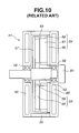
- the axial gap motor 51 comprises a case 55, a rotor shaft 52 rotatably disposed in case 55, an annular rotor 53 fixed to rotor shaft 52 to rotate therewith and a stator 54 arranged about rotor shaft 52 at a position to face rotor 53.
- Axially spaced two bearings 56 are employed for rotatably supporting rotor shaft 52 relative to case 55.
- Rotor 53 comprises a rotor back core 57, twelve flat plate magnets 58 and a rotor core 59 which are assembled to constitute one unit.
- stator 54 comprises a stator back core 60, a stator core 61 and stator coils 62 which are assembled to constitute one unit. As shown, between stator 54 and rotor 53, there is defined a certain gap 63. Near one axial end of rotor shaft 52, there is arranged an encoder 64 that detects a rotation speed (or angular position) of rotor shaft 52.
- Case 55 is formed with a water jacket 65 through which cooling water flows to cool the motor 51.
- Rotor back core 57 functions to turn a looped magnetic flux about the axis X of rotor shaft 52. That is, for operating the motor 51, a looped magnetic flux that has passed through one group of flat plate magnets 58 is needed to turn in a circumferential direction for passing through the other group of flat plate magnets 58 and stator 54 next.
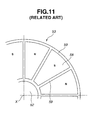
- Fig. 11 is an enlarged view of a part of rotor 53 taken from gap 63 between stator 54 and rotor 53 (see Fig. 10). As shown, with the presence of twelve flat plate magnets 58, rotor 53 has twelve poles, six N-poles and six S-poles alternately arranged. These flat plate magnets 58 are exposed at their main surfaces to gap 63 that is defined between stator 54 and rotor 53.
- axial gap motor 51 In axial gap motor 51 mentioned hereinabove, the output or power of the same depends substantially on quantity of magnetism possessed by rotor 53. Thus, when higher output is required, it is necessary to increase the number of flat plate magnets 58. However, due to the nature of the flat arrangement of flat plate magnets 58 that has been explained hereinabove, increasing the number of the magnets 58 directly brings about enlargement in size of rotor 53. Of course, in this case, the axial gap motor 51 becomes bulky. Furthermore, due to its inherent construction, the motor 51 tends to have even magnetic resistance and thus practical usage of a reluctance torque is poor. Furthermore, usage of rotor back core 57 increases the cost of motor 51.
- an object of the present invention is to provide an axial gap motor which is free of the above-mentioned drawbacks.
- an axial gap motor which can effectively use a reluctance torque and thus generate a higher power without increasing the size of the motor.
- an axial gap motor which comprises a rotor shaft rotatable about its axis; a rotor fixed to the rotor shaft to rotate therewith, the rotor including a plurality of magnets; and a stator disposed about the rotor shaft at a position to coaxially face the rotor, the stator including a plurality of coils, wherein the magnets of the rotor have each opposed pole faces that extend in a direction other than a direction that is perpendicular to the axis of the rotor shaft.
- an axial gap motor which comprises a case; a rotor shaft rotatably installed in the case, the rotor shaft having an axis about which the rotor shaft is rotatable; an annular rotor fixed to the rotor shaft to rotate therewith, the annular rotor including a plurality of magnets which are arranged about the axis of the rotor shaft at equally spaced intervals; and an annular stator disposed about the rotor shaft at a potion to coaxially face the annular rotor, the annular stator including a plurality of coils which are arranged about the axis of the rotor shaft at evenly spaced intervals, wherein the magnets of the annular rotor are of a flat plate type and opposed pole faces of each magnet extend in a direction other than a direction that is perpendicular to the axis of the rotor shaft.
- an axial gap motor which comprises a case; a rotor shaft rotatably installed in the case, the rotor shaft having an axis about which the rotor shaft is rotatable; an annular rotor fixed to the rotor shaft to rotate therewith, the annular rotor including a plurality of magnets which are arranged about the axis of the rotor shaft at equally spaced intervals; and first and second annular stators disposed about the rotor shaft at positions to put therebetween the annular rotor, each of the first and second annular stators including a plurality of coils which are arranged about the axis of the rotor shaft at evenly spaced intervals, wherein the magnets of the annular rotor are of a flat plate type and opposed pole faces of each magnet extend in a direction other than a direction that is perpendicular to the axis of the rotor shaft.
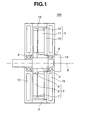
- FIG. 1 of the drawings there is shown in a sectional form an axial gap motor 100 of single rotor-single stator type, which is a first embodiment of the present invention.
- Axial gap motor 100 of this first embodiment comprises a case 5, a rotor shaft 2 rotatably installed in case 5, an annular rotor 3 concentrically disposed on rotor shaft 2 to rotate therewith and a stator 4 concentrically arranged about rotor shaft 52 at a position to coaxially face rotor 3.
- Two bearings 6 are held on axially spaced portions of case 5 to rotatably support rotor shaft 2 relative to case 5, as shown.
- Annular rotor 3 comprises a rotor ring 7, twelve magnets 8 and a rotor core 9 which are assembled to constitute one unit.
- Rotor core 9 is made of a pressed iron-powder, through which magnetism can penetrate. The detail of the annular rotor 3 will be described hereinafter.
- Stator 4 comprises a stator back core 10, a stator core 11 and stator coils 12 which are assembled to constitute one unit.
- Stator back core 10 is arranged to fix stator core 11 to case 5 and functions to turn a looped magnetic flux of stator core 11 about the axis X of rotor shaft 2.
- Stator coils 12 are arranged on equally spaced portions of a peripheral edge of stator core 11.
- stator 4 As shown, between stator 4 and rotor 3, there is defined a certain gap 13.
- an encoder 14 that detects a rotation speed (or angular position) of rotor shaft 2.
- Case 5 is formed with a water jacket 15 through which cooling water flows to cool entire construction of motor 100.
- the annular rotor 3 has a unique structure as will be described in the following.
- each of magnets 8 held by rotor ring 7 and rotor core 9 is shaped into a flat rectangular plate.
- the twelve flat plate magnets 8 are arranged about the axis X of rotor shaft 2 at evenly spaced intervals, and thus, the entire construction of annular rotor 3 is shaped like a water wheel. That is, in an assembled condition, opposed two major flat surfaces 8a and 8b (or pole faces) of each of the magnets 8 are perpendicular to an imaginary plane (not shown) that is perpendicular to the axis X of rotor shaft 2. In other words, the major flat surfaces 8a and 8b of the magnets 8 are perpendicular to an imaginary plane (not shown) that is substantially defined by the gap 13.
- adjacent two of the magnets 8 are all arranged in a reversed way regarding N-S position. That is, as shown, adjacent two of the magnets 8 are all arranged in such a manner that mutually facing major surfaces (or mutually facing pole faces) thereof have the same polarity for example, respective N-polarity or respective S-polarity.
- each of flat plate magnets 8 has two opposed major surfaces 8a and 8b.
- Fig. 4A shows the arrangement of the above-mentioned related art of Fig. 11, and Fig. 4B shows the arrangement in the first embodiment 100.
- the motor 100 of the first embodiment can exhibit the same quantity of magnetism as the axial gap motor 51 of Fig. 10.
- Fig. 5A shows a positional relation between each magnet 58 of rotor 53 and stator core 61 of stator 54 (see Fig. 11), and Fig. 5B shows a positional relation between each magnet 8 of rotor 3 and stator core 11 of stator 4 (see Fig. 1).
- the magnetic fluxes (see Fig. 10) run axially from stator 54 toward rotor 53 passing through the perpendicularly facing flat plate magnets 58 and constitute looped magnetic fluxes.
- spaces defined between elements of stator core 61 face the pole faces of flat plate magnets 58, and thus, the gap 63 fails to have any portion through which Q-axis magnetic flux passes.
- the conventional axial gap motor 51 hardly produces a reluctance torque. While, in the unique positional relation shown in Fig.
- stator core 11 of stator 4 has two (viz., first and second) groups of paired elements of stator core 11, in which the paired elements of the first group are incorporated with one of the magnets 8 and those of the second group are incorporated with a part of rotor core 9 which is put between adjacent two magnets 8.
- the first group can produce a magnetic toque and the second group can produce a reluctance torque.
- Fig. 6 shows a first modification 3A of annular rotor 3 employed in the axial gap motor 100 of the first embodiment.
- each magnet 8A includes two mutually angled rectangular plate portions that have radially inner ends thereof integrated.
- each magnet 8A has a generally V-shaped cross section.
- the twelve magnets 8A are arranged about the axis X of rotor shaft 2 at evenly spaced intervals having the integrated bottom portions of the two rectangular plate portions of each magnet 8A directed toward the axis X of rotor shaft 2. Furthermore, the two mutually angled rectangular plate portions of each magnet 8A have mutually facing major surfaces that have the same polarity N (or S) and mutually opposed major surfaces that have the same polarity S (or N). Furthermore, as shown, adjacent two magnets 8A are so arranged that mutually closed rectangular plate portions of the two magnets 8A have mutually facing major surfaces that have different polarities S and N (or N and S).
- the quantity of magnetism can be increased without increasing the diameter of the motor 100, for the reason as has been mentioned hereinabove.
- the gap 13 faces rotor core 9 of rotor 3 (and 3A) that is constructed by pressed iron-powder, a reluctance torque is effectively produced by the motor 100, which promotes increase in power of the motor 100.
- Fig. 7 shows a second modification 3B of annular rotor employed in the axial gap motor 100 of the first embodiment.
- each flat plate magnet 8B is angled relative to an imaginary plane (not shown) that extends perpendicular to the axis X of rotor shaft 2. More specifically, as is understood from the drawing, adjacent two of the flat plate magnets 8B are angled to each other and angled with respect to an imaginary plane that extends in parallel with the axis X of rotor shaft 2 with one paired pole faces N-N (or S-S) facing forward and the other paired pole faces S-S (or N-N) facing rearward.
- the quantity of magnetism is much increased due to a three-dimensional arrangement of the magnets 8B in rotor 3B.
- the major surface of each magnet 8B can be much increased.
- the distance from the major surface of each magnet 8B to the stator 4 is reduced, and thus, the magnetic resistance is reduced increasing the quantity of magnetic fluxes.
- the thickness of rotor 3B is reduced, the volume of motor 100 is reduced and thus the power density of motor 100 is increased.
- FIG. 8 is a development elevation of the single rotor-single stator type axial gap motor 100 to which the modified rotor 3B of Fig. 7 is practically applied.
- stator 4 has stator teeth each having a V-shape coil, W-phase coil or U-phase coil mounted therearound.
- One unit including three types of coils V, W and U is in incorporation with paired magnets 8B that are angled to open toward the unit.
- each part of rotor core 9 that is substantially enclosed by paired magnets 8B and the unit of coils V, W and U is denoted by numeral 21(9).
- the paired magnets 8B that are angled to each other have mutually facing surfaces that carry the same polarity N (or S) and the other surfaces that carry the other same polarity S (or N).
- FIG. 2 there is shown in a sectional form an axial gap motor 200 of single rotor-double stator type, which is a second embodiment of the present invention.
- axial gap motor 200 of this second embodiment is similar to the above-mentioned motor 100 of the first embodiment, only portions or parts that are different from those of the motor 100 will be described in detail in the following.
- an additional stator 4' is further employed, which is arranged at an axially opposite position of stator 4 with respect to rotor 3.
- these two stators 4 and 4' will be called first and second stators in the following description.
- First and second stators 4 and 4' are substantially the same in construction. That is, like stator 4, stator 4' comprises a stator back core 10', a stator core 11' and stator coils 12' which are assembled to constitute one unit. Stator back core 10' is arranged to fix stator core 11' to case 5 and functions to turn a looped magnetic flux of stator core 11' about the axis X of rotor shaft 2. Stator coils 12' are arranged on equally spaced portions of a peripheral edge of stator core 11'.
- first and second stators 4 and 4' are coaxially disposed about rotor shaft 2 having rotor 3 put therebetween.
- a certain gap 13 is defined between stator 4' and rotor 3, like the gap 13 between stator 4 and rotor 3.
- rotor 3 As rotor 3, the above-mentioned rotors 3, 3A and 3B respectively shown in Figs. 3B, 6 and 7 are usable.
- Fig. 9 is a development elevation of single rotor-double stator type axial gap motor 200 to which a third modification 3C of annular rotor is practically applied.
- the third modification 3C of rotor has, in addition to the group of the above-mentioned paired magnets 8B, another group of paired magnets 8B' that are incorporated with the additional stator 4'.
- the two groups of paired magnets 8B and 8B' are symmetrically arranged with respect to an imaginary plane Y that is perpendicular to the axis X of rotor shaft 2, and mutually facing major surfaces of the two groups of paired magnets 8B and 8B' have different polarities, that is, N-polarity and S-polarity or S-polarity and N-polarity, as shown.
- the quantity of magnetism produced by the motor 200 of this embodiment is increased as compared with the motor 100 and thus the motor 200 can generate a higher power than the motor 100.
- the motor 200 employing the third modification 3C of rotor can generate much high power due to employment of two groups of paired magnets 8B and 8B' in addition to the two stators 4 and 4'.
Landscapes
- Engineering & Computer Science (AREA)
- Power Engineering (AREA)
- Permanent Magnet Type Synchronous Machine (AREA)
- Permanent Field Magnets Of Synchronous Machinery (AREA)
- Iron Core Of Rotating Electric Machines (AREA)
Abstract
Description
Claims (20)
- An axial gap motor (100, 200) comprising:wherein the magnets (8) of the rotor have each opposed pole faces that extend in a direction other than a direction that is perpendicular to the axis (X) of the rotor shaft (2).a rotor shaft (2) rotatable about its axis (X);a rotor (3) fixed to the rotor shaft to rotate therewith, the rotor including a plurality of magnets (8); anda stator (4) disposed about the rotor shaft at a position to coaxially face the rotor, the stator including a plurality of coils (12),
- An axial gap motor as claimed in Claim 1, in which the magnets (8) of the rotor are of a flat plate type and in which each magnet has two major flat surfaces (8a, 8b) that extend in parallel with the axis (X) of the rotor shaft (2).
- An axial gap motor as claimed in Claim 1 or 2, in which the magnets (8) are arranged about the axis (X) of the rotor shaft (2) at evenly spaced intervals.
- An axial gap motor as claimed in Claim 1, 2 or 3, in which adjacent two (8, 8) of the magnets are arranged in such a manner that mutually facing major surfaces (8a, 8a) (8b, 8b) thereof bear the same polarity.
- An axial gap motor as claimed in Claim 1, 2, 3 or 4, in which the magnets (8) are housed in a holder structure including a rotor core (9) and a rotor ring (7), so that the rotor is shaped like a water wheel.
- An axial gap motor as claimed in Claim 1, in which each of the magnets (8A) includes two mutually angled rectangular plate portions with radially inner ends integrated, so that the magnet (8A) has a generally V-shaped cross section, and in which the magnets (8A) are arranged about the axis (X) of the rotor shaft (2) at evenly spaced intervals having the integrated inner ends of the two plate portions of each magnet directed toward the axis (X) of the rotor shaft (2).
- An axial gap motor as claimed in Claim 6, in which the two mutually angled rectangular plate portions of each magnet (8A) have mutually facing major surfaces that have the same polarity and mutually opposed major surfaces that have the other same polarity.
- An axial gap motor as claimed in Claim 7, in which adjacent two magnets (8A) are so arranged that mutually closed rectangular plate portions of the two magnets are mutually facing major surfaces that have different polarities.
- An axial gap motor as claimed in Claim 1, in which the magnets of the rotor (3) are of a flat plate type and in which adjacent two of the flat plate magnets (8B) are angled to each other and angled with respect to an imaginary plane that extends in parallel with the axis (X) of the rotor shaft (2) with one paired mutually facing pole faces facing in a first direction and the other paired mutually opposed pole faces facing in a second direction.
- An axial gap motor as claimed in Claim 1, further comprising an additional stator (4') that is disposed about the rotor shaft (2) at a position opposite to said stator (4) with respect to the rotor (3).
- An axial gap motor as claimed in Claim 10, in which the magnets (8) of the rotor are of a flat plate type and in which each magnet (8) has two major flat surfaces that extend in parallel with the axis (X) of the rotor shaft (2).
- An axial gap motor as claimed in Claim 11, in which the flat type magnets (8) are arranged about the axis of the rotor shaft at evenly spaced intervals.
- An axial gap motor as claimed in Claim 12, in which adjacent two of the flat plate type magnets (8) are arranged in such a manner that mutually facing major surfaces (8a, 8a), (8b, 8b) thereof bear the same polarity.
- An axial gap motor as claimed in Claim 10, in which each of the magnets (8A) includes two mutually angled rectangular plate portions with radially inner ends integrated, so that the magnet has a generally V-shaped cross section, and in which the magnets (8A) are arranged about the axis of the rotor shaft at evenly spaced intervals having the integrated inner ends of the two plate portions of each magnet directed toward the axis (X) of the rotor shaft (2).
- An axial gap motor as claimed in Claim 10, in which the magnets of the rotor are of a flat plate type and include first and second groups of magnets (8B, 8B') which are positioned at axially different portions with respect to the axis (X) of the rotor shaft (2).
- An axial gap motor as claimed in Claim 15, in which adjacent two of the flat plate magnets of the first group (8B) are angled to each other and angled with respect to an imaginary plane that extends in parallel with the axis of the rotor shaft with one paired mutually facing pole faces facing in a first direction and the other paired mutually opposed pole faces facing in a second direction and in which adjacent two of the flat plate magnets of the second group (8B') are angled to each other and angled with respect to the imaginary plane with one paired mutually facing pole faces facing in the second direction and the other paired mutually opposed pole faces facing in the first direction.
- An axial gap motor as claimed in Claim 1, in which the stator (4) comprises a stator back core (10), a stator core (11) and stator coils (12) which are assembled to constitute one unit, in which the stator coils (12) are arranged on equally spaced portions of a peripheral edge of the stator core, and in which the stator coils include a U-phase coil (U), a V-phase coil (V) and a W-phase coil (W).
- An axial gap motor as claimed in Claim 10, in which the stator and the additional stator each comprise a stator back core (10, 10'), a stator core (11, 11') and stator coils (12, 12') which are assembled to constitute one unit, in which the stator coils (12, 12') are arranged on equally spaced portions of a peripheral edge of the stator core, and in which the stator coils include a U-phase coil (U), a V-phase coil (V) and a W-phase coil (W).
- An axial gap motor (100) comprising:wherein the magnets (8) of the annular rotor are of a flat plate type and opposed pole faces (8a, 8b) of each magnet (8) extend in a direction other than a direction that is perpendicular to the axis (X) of the rotor shaft (2).a case (5);a rotor shaft (2) rotatably installed in the case (5), the rotor shaft having an axis (X) about which the rotor shaft is rotatable;an annular rotor (3) fixed to the rotor shaft to rotate therewith, the annular rotor including a plurality of magnets (8) which are arranged about the axis (X) of the rotor shaft (2) at equally spaced intervals; andan annular stator (4) disposed about the rotor shaft (2) at a potion to coaxially face the annular rotor (3), the annular stator (4) including a plurality of coils (12) which are arranged about the axis (X) of the rotor shaft (2) at evenly spaced intervals,
- An axial gap motor (200) comprising:wherein the magnets (8) of the annular rotor (2) are of a flat plate type and opposed pole faces of each magnet extend in a direction other than a direction that is perpendicular to the axis (X) of the rotor shaft (2).a case (5);a rotor shaft (2) rotatably installed in the case, the rotor shaft (2) having an axis (X) about which the rotor shaft is rotatable;an annular rotor (3) fixed to the rotor shaft (2) to rotate therewith, the annular rotor (3) including a plurality of magnets (8) which are arranged about the axis (X) of the rotor shaft at equally spaced intervals; andfirst and second annular stators (4, 4') disposed about the rotor shaft at positions to put therebetween the annular rotor, each of the first and second annular stators including a plurality of coils (12, 12') which are arranged about the axis (X) of the rotor shaft (2) at evenly spaced intervals,
Applications Claiming Priority (2)
| Application Number | Priority Date | Filing Date | Title |
|---|---|---|---|
| JP2003416591 | 2003-12-15 | ||
| JP2003416591A JP4193685B2 (en) | 2003-12-15 | 2003-12-15 | Axial gap motor structure |
Publications (3)
| Publication Number | Publication Date |
|---|---|
| EP1544978A2 true EP1544978A2 (en) | 2005-06-22 |
| EP1544978A3 EP1544978A3 (en) | 2008-01-23 |
| EP1544978B1 EP1544978B1 (en) | 2010-04-21 |
Family
ID=34510587
Family Applications (1)
| Application Number | Title | Priority Date | Filing Date |
|---|---|---|---|
| EP04028377A Expired - Lifetime EP1544978B1 (en) | 2003-12-15 | 2004-11-30 | Axial gap electric motor |
Country Status (5)
| Country | Link |
|---|---|
| US (1) | US7315102B2 (en) |
| EP (1) | EP1544978B1 (en) |
| JP (1) | JP4193685B2 (en) |
| CN (1) | CN1630170A (en) |
| DE (1) | DE602004026675D1 (en) |
Cited By (4)
| Publication number | Priority date | Publication date | Assignee | Title |
|---|---|---|---|---|
| WO2008098867A1 (en) * | 2007-02-15 | 2008-08-21 | Siemens Aktiengesellschaft | Recycling machine, in particular comminuting machine |
| CN103812245A (en) * | 2012-11-09 | 2014-05-21 | 财团法人工业技术研究院 | Axial magnetic flux magnetic collection rotor structure |
| EP2869433A1 (en) * | 2013-10-30 | 2015-05-06 | SC BMEnergy SRL | Axial flux permanent magnet electrical machine with magnetic flux concentration |
| EP2066004A4 (en) * | 2006-09-19 | 2016-10-19 | Daikin Ind Ltd | ENGINE AND COMPRESSOR |
Families Citing this family (45)
| Publication number | Priority date | Publication date | Assignee | Title |
|---|---|---|---|---|
| US8058762B2 (en) * | 2005-01-19 | 2011-11-15 | Daikin Industries, Ltd. | Rotor, axial gap type motor, method of driving motor, and compressor |
| FR2895844A1 (en) | 2006-01-03 | 2007-07-06 | Leroy Somer Moteurs | Radial or disk shaped rotating electrical machine, has pole piece associated with permanent magnets to concentrate magnetic flux of magnets, where magnets define three different magnetization directions |
| US8030816B2 (en) * | 2006-06-06 | 2011-10-04 | Honda Motor Co., Ltd. | Motor and motor control device |
| JP4169055B2 (en) * | 2006-07-14 | 2008-10-22 | ダイキン工業株式会社 | Rotating electric machine |
| US7737594B2 (en) * | 2006-12-01 | 2010-06-15 | Honda Motor Co., Ltd. | Axial gap type motor |
| WO2008068977A1 (en) * | 2006-12-06 | 2008-06-12 | Honda Motor Co., Ltd. | Axial gap motor |
| JP4394115B2 (en) * | 2006-12-26 | 2010-01-06 | 本田技研工業株式会社 | Axial gap type motor |
| JP2008271640A (en) * | 2007-04-17 | 2008-11-06 | Honda Motor Co Ltd | Axial gap type motor |
| JP4707696B2 (en) * | 2007-06-26 | 2011-06-22 | 本田技研工業株式会社 | Axial gap type motor |
| JP4961302B2 (en) * | 2007-08-29 | 2012-06-27 | 本田技研工業株式会社 | Axial gap type motor |
| US7977843B2 (en) * | 2007-10-04 | 2011-07-12 | Honda Motor Co., Ltd. | Axial gap type motor |
| JP4729551B2 (en) * | 2007-10-04 | 2011-07-20 | 本田技研工業株式会社 | Axial gap type motor |
| GB0800225D0 (en) * | 2008-01-07 | 2008-02-13 | Evo Electric Ltd | A rotor for an electrical machine |
| TWI517526B (en) * | 2008-03-19 | 2016-01-11 | 好根那公司 | Permanent magnet machine |
| US7906883B2 (en) * | 2008-06-02 | 2011-03-15 | Honda Motor Co., Ltd. | Axial gap motor |
| US8049389B2 (en) * | 2008-06-02 | 2011-11-01 | Honda Motor Co., Ltd. | Axial gap motor |
| JP4678549B2 (en) * | 2008-10-09 | 2011-04-27 | 本田技研工業株式会社 | Axial gap type motor |
| JP2011010375A (en) * | 2009-06-23 | 2011-01-13 | Hokkaido Univ | Axial motor |
| JP5440079B2 (en) * | 2009-10-01 | 2014-03-12 | 信越化学工業株式会社 | Rotor for axial gap type permanent magnet type rotating machine and axial gap type permanent magnet type rotating machine |
| US9270150B2 (en) | 2009-12-16 | 2016-02-23 | Clear Path Energy, Llc | Axial gap rotating electrical machine |
| KR20120103641A (en) * | 2009-12-16 | 2012-09-19 | 클리어 패쓰 에너지, 엘엘씨 | Floating underwater support structure |
| RU2427067C1 (en) * | 2009-12-25 | 2011-08-20 | Сергей Михайлович Есаков | Magnetoelectric generator |
| US8468898B2 (en) * | 2010-10-28 | 2013-06-25 | General Electric Company | Method and apparatus for continuous sectional magnetic encoding to measure torque on large shafts |
| JP5538448B2 (en) * | 2012-01-19 | 2014-07-02 | 富士重工業株式会社 | Axial gap type power generator |
| WO2014026006A2 (en) * | 2012-08-08 | 2014-02-13 | Marvell World Trade Ltd. | Controlling fan motors using capacitive sensing |
| US10559864B2 (en) | 2014-02-13 | 2020-02-11 | Birmingham Technologies, Inc. | Nanofluid contact potential difference battery |
| US10797573B2 (en) * | 2014-04-16 | 2020-10-06 | Power It Perfect, Inc. | Axial motor/generator having multiple inline stators and rotors with stacked/layered permanent magnets, coils, and a controller |
| US10298104B2 (en) * | 2014-04-16 | 2019-05-21 | Power It Perfect, Inc. | Electrical motor and electrical generator device |
| EP3026798B1 (en) | 2014-11-25 | 2020-10-14 | Black & Decker Inc. | Brushless motor for a power tool |
| US10328566B2 (en) | 2015-10-14 | 2019-06-25 | Black & Decker Inc. | Brushless motor system for power tools |
| GB201717871D0 (en) * | 2017-10-30 | 2017-12-13 | Romax Tech Limited | Motor |
| DE102017127157A1 (en) * | 2017-11-17 | 2019-05-23 | Gkn Sinter Metals Engineering Gmbh | Rotor for an axial flux motor |
| US10358039B1 (en) * | 2018-09-14 | 2019-07-23 | Edward Michael Frierman | Vehicle turbine system |
| US11264877B2 (en) * | 2018-10-02 | 2022-03-01 | The University Of Akron | Axial flux machine |
| GB2583974B (en) * | 2019-05-17 | 2023-12-06 | Time To Act Ltd | Improvements to the construction of axial flux rotary generators |
| TWI711246B (en) * | 2019-06-03 | 2020-11-21 | 威剛科技股份有限公司 | Axial rotor of axial gap type electrical rotation machine |
| US10938258B1 (en) * | 2019-10-30 | 2021-03-02 | Maxxwell Motors, Inc. | Rotor for an axial flux rotating electrical machine compressed with a band |
| CN112910125A (en) * | 2019-11-19 | 2021-06-04 | 通用汽车环球科技运作有限责任公司 | Axial flux motor assembly with variable thickness rotor and rotor with built-in magnets |
| US11223249B2 (en) * | 2020-05-13 | 2022-01-11 | Kobe Steel, Ltd. | Electric motor |
| DE102020209436A1 (en) * | 2020-07-27 | 2022-01-27 | Robert Bosch Gesellschaft mit beschränkter Haftung | Rotor device and electric motor |
| CN114552815B (en) | 2020-11-26 | 2025-05-02 | 通用汽车环球科技运作有限责任公司 | Direct contact cooling of axial flux motor stators |
| US11424666B1 (en) | 2021-03-18 | 2022-08-23 | Maxxwell Motors, Inc. | Manufactured coil for an electrical machine |
| US20230067006A1 (en) * | 2021-07-27 | 2023-03-02 | Ramesh Chandra | Flat dc electric machine |
| EP4142125A1 (en) * | 2021-08-26 | 2023-03-01 | Universidad de Alcalá (UAH) | Miniaturized electromagnetic rotary actuator |
| JP7797948B2 (en) * | 2022-04-07 | 2026-01-14 | 株式会社明電舎 | Axial gap motor |
Family Cites Families (13)
| Publication number | Priority date | Publication date | Assignee | Title |
|---|---|---|---|---|
| US3688306A (en) * | 1970-03-18 | 1972-08-29 | Nippon Denso Co | Digital type rotational angle detector |
| US3633055A (en) * | 1970-06-22 | 1972-01-04 | Molon Motor & Coil Corp | Permanent magnet motor |
| DE2337905A1 (en) * | 1973-07-26 | 1975-02-13 | Gerhard Berger Fabrikation Ele | SELF-STARTING SYNCHRONOUS MOTOR WITH PERMANENT MAGNETIC RUNNING |
| US4814654A (en) * | 1984-10-12 | 1989-03-21 | Gerfast Sten R | Stator or rotor based on permanent magnet segments |
| JPS6181773U (en) | 1984-10-29 | 1986-05-30 | ||
| FR2606951A1 (en) * | 1986-11-13 | 1988-05-20 | Alsthom Cgee | Motor with magnets |
| JPH0349545A (en) | 1989-07-17 | 1991-03-04 | Toyota Motor Corp | Permanent magnet type synchronous motor |
| JPH03289342A (en) | 1990-04-05 | 1991-12-19 | Hitachi Metals Ltd | Flat brushless motor |
| US5245238A (en) * | 1991-04-30 | 1993-09-14 | Sundstrand Corporation | Axial gap dual permanent magnet generator |
| US5619087A (en) * | 1992-03-18 | 1997-04-08 | Kabushiki Kaisha Toshiba | Axial-gap rotary-electric machine |
| JP3630332B2 (en) | 1995-01-20 | 2005-03-16 | 株式会社Neomax | Permanent magnet rotor |
| US6411002B1 (en) * | 1996-12-11 | 2002-06-25 | Smith Technology Development | Axial field electric machine |
| JPH11187635A (en) | 1997-12-19 | 1999-07-09 | Sawafuji Electric Co Ltd | Flat rotating machine |
-
2003
- 2003-12-15 JP JP2003416591A patent/JP4193685B2/en not_active Expired - Fee Related
-
2004
- 2004-11-30 DE DE602004026675T patent/DE602004026675D1/en not_active Expired - Lifetime
- 2004-11-30 EP EP04028377A patent/EP1544978B1/en not_active Expired - Lifetime
- 2004-12-07 US US11/004,824 patent/US7315102B2/en not_active Expired - Lifetime
- 2004-12-14 CN CN200410102104.XA patent/CN1630170A/en active Pending
Cited By (5)
| Publication number | Priority date | Publication date | Assignee | Title |
|---|---|---|---|---|
| EP2066004A4 (en) * | 2006-09-19 | 2016-10-19 | Daikin Ind Ltd | ENGINE AND COMPRESSOR |
| WO2008098867A1 (en) * | 2007-02-15 | 2008-08-21 | Siemens Aktiengesellschaft | Recycling machine, in particular comminuting machine |
| CN103812245A (en) * | 2012-11-09 | 2014-05-21 | 财团法人工业技术研究院 | Axial magnetic flux magnetic collection rotor structure |
| CN103812245B (en) * | 2012-11-09 | 2016-02-10 | 财团法人工业技术研究院 | Axial magnetic flux magnetic collection rotor structure |
| EP2869433A1 (en) * | 2013-10-30 | 2015-05-06 | SC BMEnergy SRL | Axial flux permanent magnet electrical machine with magnetic flux concentration |
Also Published As
| Publication number | Publication date |
|---|---|
| EP1544978B1 (en) | 2010-04-21 |
| JP2005176575A (en) | 2005-06-30 |
| EP1544978A3 (en) | 2008-01-23 |
| US20050127769A1 (en) | 2005-06-16 |
| US7315102B2 (en) | 2008-01-01 |
| JP4193685B2 (en) | 2008-12-10 |
| CN1630170A (en) | 2005-06-22 |
| DE602004026675D1 (en) | 2010-06-02 |
Similar Documents
| Publication | Publication Date | Title |
|---|---|---|
| EP1544978B1 (en) | Axial gap electric motor | |
| US10644550B2 (en) | Rotor for rotating electric machine | |
| US7737594B2 (en) | Axial gap type motor | |
| US6172438B1 (en) | Two-phase permanent-magnet electric rotating machine | |
| US11799337B2 (en) | Rotating electric machine | |
| US20060028082A1 (en) | Interior permanent magnet electric rotating machine | |
| JP3182502B2 (en) | Hybrid type step motor | |
| US5723921A (en) | Hybrid-type stepping motor | |
| CN101779366A (en) | Axial gap type motor | |
| US5856714A (en) | Hybrid type stepping motor | |
| JP2014131376A (en) | Rotor, and dynamo-electric machine using the same | |
| KR101502115B1 (en) | Brushless motor | |
| CN102624108B (en) | Stator for axial clearance type motor and axial clearance type motor | |
| WO2017195263A1 (en) | Permanent magnet motor | |
| US20220060070A1 (en) | Rotating electric machine | |
| KR20220164175A (en) | Motor including double stators | |
| US6236133B1 (en) | Three-phase brushless motor | |
| JP6309065B1 (en) | Rotating electric machine rotor and rotating electric machine using the same | |
| JP2001298922A (en) | Vernier motor | |
| JP5940354B2 (en) | Electric power steering system motor rotor and electric power steering system motor | |
| US7728465B2 (en) | Hybrid stepping motor having high torque density | |
| JP3410519B2 (en) | Three-phase claw-pole type permanent magnet type rotating electric machine | |
| JP2006074989A (en) | Axial gap type rotating electrical machine | |
| JP2016178863A (en) | Brushless motor for vehicle | |
| JP2000125533A (en) | motor |
Legal Events
| Date | Code | Title | Description |
|---|---|---|---|
| PUAI | Public reference made under article 153(3) epc to a published international application that has entered the european phase |
Free format text: ORIGINAL CODE: 0009012 |
|
| 17P | Request for examination filed |
Effective date: 20041130 |
|
| AK | Designated contracting states |
Kind code of ref document: A2 Designated state(s): AT BE BG CH CY CZ DE DK EE ES FI FR GB GR HU IE IS IT LI LU MC NL PL PT RO SE SI SK TR |
|
| AX | Request for extension of the european patent |
Extension state: AL HR LT LV MK YU |
|
| PUAL | Search report despatched |
Free format text: ORIGINAL CODE: 0009013 |
|
| AK | Designated contracting states |
Kind code of ref document: A3 Designated state(s): AT BE BG CH CY CZ DE DK EE ES FI FR GB GR HU IE IS IT LI LU MC NL PL PT RO SE SI SK TR |
|
| AX | Request for extension of the european patent |
Extension state: AL HR LT LV MK YU |
|
| 17Q | First examination report despatched |
Effective date: 20080722 |
|
| AKX | Designation fees paid |
Designated state(s): DE FR GB |
|
| RTI1 | Title (correction) |
Free format text: AXIAL GAP ELECTRIC MOTOR |
|
| GRAP | Despatch of communication of intention to grant a patent |
Free format text: ORIGINAL CODE: EPIDOSNIGR1 |
|
| GRAS | Grant fee paid |
Free format text: ORIGINAL CODE: EPIDOSNIGR3 |
|
| GRAA | (expected) grant |
Free format text: ORIGINAL CODE: 0009210 |
|
| AK | Designated contracting states |
Kind code of ref document: B1 Designated state(s): DE FR GB |
|
| REG | Reference to a national code |
Ref country code: GB Ref legal event code: FG4D |
|
| REF | Corresponds to: |
Ref document number: 602004026675 Country of ref document: DE Date of ref document: 20100602 Kind code of ref document: P |
|
| PLBE | No opposition filed within time limit |
Free format text: ORIGINAL CODE: 0009261 |
|
| STAA | Information on the status of an ep patent application or granted ep patent |
Free format text: STATUS: NO OPPOSITION FILED WITHIN TIME LIMIT |
|
| 26N | No opposition filed |
Effective date: 20110124 |
|
| REG | Reference to a national code |
Ref country code: FR Ref legal event code: PLFP Year of fee payment: 12 |
|
| REG | Reference to a national code |
Ref country code: FR Ref legal event code: PLFP Year of fee payment: 13 |
|
| REG | Reference to a national code |
Ref country code: FR Ref legal event code: PLFP Year of fee payment: 14 |
|
| REG | Reference to a national code |
Ref country code: FR Ref legal event code: PLFP Year of fee payment: 15 |
|
| REG | Reference to a national code |
Ref country code: FR Ref legal event code: PLFP Year of fee payment: 16 |
|
| PGFP | Annual fee paid to national office [announced via postgrant information from national office to epo] |
Ref country code: DE Payment date: 20191119 Year of fee payment: 16 |
|
| PGFP | Annual fee paid to national office [announced via postgrant information from national office to epo] |
Ref country code: FR Payment date: 20191014 Year of fee payment: 16 |
|
| PGFP | Annual fee paid to national office [announced via postgrant information from national office to epo] |
Ref country code: GB Payment date: 20191129 Year of fee payment: 16 |
|
| REG | Reference to a national code |
Ref country code: DE Ref legal event code: R119 Ref document number: 602004026675 Country of ref document: DE |
|
| GBPC | Gb: european patent ceased through non-payment of renewal fee |
Effective date: 20201130 |
|
| PG25 | Lapsed in a contracting state [announced via postgrant information from national office to epo] |
Ref country code: FR Free format text: LAPSE BECAUSE OF NON-PAYMENT OF DUE FEES Effective date: 20201130 |
|
| PG25 | Lapsed in a contracting state [announced via postgrant information from national office to epo] |
Ref country code: GB Free format text: LAPSE BECAUSE OF NON-PAYMENT OF DUE FEES Effective date: 20201130 Ref country code: DE Free format text: LAPSE BECAUSE OF NON-PAYMENT OF DUE FEES Effective date: 20210601 |