EP1544797A2 - Coprocesseur de calcul d'une transformation pour la compression vidéo à haute performance et à faible consommation d'énergie - Google Patents
Coprocesseur de calcul d'une transformation pour la compression vidéo à haute performance et à faible consommation d'énergie Download PDFInfo
- Publication number
- EP1544797A2 EP1544797A2 EP04257767A EP04257767A EP1544797A2 EP 1544797 A2 EP1544797 A2 EP 1544797A2 EP 04257767 A EP04257767 A EP 04257767A EP 04257767 A EP04257767 A EP 04257767A EP 1544797 A2 EP1544797 A2 EP 1544797A2
- Authority
- EP
- European Patent Office
- Prior art keywords
- matrix
- transform
- data
- multiplying
- input
- Prior art date
- Legal status (The legal status is an assumption and is not a legal conclusion. Google has not performed a legal analysis and makes no representation as to the accuracy of the status listed.)
- Withdrawn
Links
Images
Classifications
-
- H—ELECTRICITY
- H04—ELECTRIC COMMUNICATION TECHNIQUE
- H04N—PICTORIAL COMMUNICATION, e.g. TELEVISION
- H04N19/00—Methods or arrangements for coding, decoding, compressing or decompressing digital video signals
- H04N19/42—Methods or arrangements for coding, decoding, compressing or decompressing digital video signals characterised by implementation details or hardware specially adapted for video compression or decompression, e.g. dedicated software implementation
- H04N19/436—Methods or arrangements for coding, decoding, compressing or decompressing digital video signals characterised by implementation details or hardware specially adapted for video compression or decompression, e.g. dedicated software implementation using parallelised computational arrangements
-
- H—ELECTRICITY
- H04—ELECTRIC COMMUNICATION TECHNIQUE
- H04N—PICTORIAL COMMUNICATION, e.g. TELEVISION
- H04N19/00—Methods or arrangements for coding, decoding, compressing or decompressing digital video signals
- H04N19/42—Methods or arrangements for coding, decoding, compressing or decompressing digital video signals characterised by implementation details or hardware specially adapted for video compression or decompression, e.g. dedicated software implementation
-
- H—ELECTRICITY
- H04—ELECTRIC COMMUNICATION TECHNIQUE
- H04N—PICTORIAL COMMUNICATION, e.g. TELEVISION
- H04N19/00—Methods or arrangements for coding, decoding, compressing or decompressing digital video signals
- H04N19/60—Methods or arrangements for coding, decoding, compressing or decompressing digital video signals using transform coding
Definitions
- This disclosure is generally directed to data processing and more specifically to video compression processing.
- H.264/AVC is the latest video compression standard. It was developed by the Joint Video Team (JVT), which includes experts from the Video Coding Experts Group (VCEG) of the International Telecommunications Union (ITU-T) and the Moving Picture Experts Group (MPEG) from the International Organization for Standardisation (ISO) and the International Electrotechnical Commission (IEC).
- JVT Joint Video Team
- VCEG Video Coding Experts Group
- MPEG Moving Picture Experts Group
- IEC International Electrotechnical Commission
- H.264/AVC has many applications, including: video broadcasting over cable, satellite and DSL; video-on-demand or multimedia streaming services; conversational services over ISDN, Ethernet, LAN, wireless and mobile networks; and interactive or serial storage on optical devices such as DVD.
- H.264/AVC was designed for higher coding efficiency.
- H.264/AVC standard adopted many advanced video coding techniques.
- H.264/AVC uses a directional spatial prediction scheme to find more redundancies among pixels within a video frame.
- H.264/AVC implements multiple frames reference, weighted prediction,.de-blocking filter, variable block size and quarter sample accurate motion compensations.
- H.264/AVC uses a small, block-based, integer, and hierarchical transform.
- H.264/AVC adopts two different coding techniques.
- CABAC context adaptive based arithmetic coding
- CAVLC context adaptive variable length coding
- H.264/AVC has lower complexity than that of the Discrete Cosine Transform (DCT) in previous video compression standards.
- DCT Discrete Cosine Transform
- the Discrete Cosine Transform is one of the most important transformations in image and video processing. It has been used in many compression standards which include JPEG, H.261, H.263, MPEG-1, MPEG-2, and MPEG-4.
- the DCT was first proposed by Ahmed, Natarajan, and Rao in 1974 (see document [3] above). Their landmark paper presents an N-point DCT that can be computed with a 2N-point FFT and some additional post-processing.
- X be a 4x4 input matrix
- Y be a 4x4 output matrix
- H t be the transpose matrix of H .
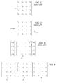
- FIGURE 2 illustrates the use of the integer transform matrix 21 to perform a 4-point one-dimensional integer transform on a vector x .
- Exemplary embodiments of the invention utilize first and second integer transform matrices to approximate the discrete cosine transform.
- An input matrix of data is multiplied by a first transform matrix of integers to produce an intermediate matrix of data.
- the intermediate matrix is multiplied by a second transform matrix of integers to produce a transform result matrix of data.
- the multiplications by the first and second transform matrices can be pipelined to increase throughput.
- a plurality of transform data paths can also be provided in parallel to increase throughput.
- FIGURES 1 through 13 discussed below, and the various embodiments used to describe the principles of the present invention in this patent document are by way of illustration only and should not be construed in any way to limit the scope of the invention. Those skilled in the art will understand that the principles of the present invention may be implemented relative to any suitable data processing application.
- FIGURE 4 illustrates factoring of the integer transform matrix 21 of FIGURES 2 and 3 according to exemplary embodiments of the invention.
- the integer transform matrix 21 is factored into constituent transform matrices 41 and 42 which, when multiplied together, produce the matrix 21.
- that transform requires twelve addition operations and four multiplication (typically data shift) operations.
- a 4 point one dimensional integer transform operation of the type illustrated in FIGURE 3 can be performed with only 8 addition operations and 2 multiplication (shift) operations.
- FIGURE 5 illustrates an exemplary implementation of the constituent factor transform matrices 41 and 42 of FIGURE 4 according to the invention.
- the transform matrices 41 and 42 are used to perform a 4x4 one dimensional integer transform on a matrix 51 of input data, in order to produce a 4x4 transform result matrix 52.
- the data components of input matrix 51 are designated by x rj in FIGURE 5 where r and j are the respective row and column indices of the matrix 51, and where r and j can each take the values 0, 1, 2 and 3.
- the data components of the transform result matrix 52 are designated as b rj in FIGURE 5, where r and j are the same respective row and column indices as described above with respect to matrix 51.
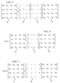
- FIGURE 6 illustrates a first stage (stage 1) integer transform operation associated with the implementation of FIGURE 5.
- the transform matrix 41 is used as a first stage transform matrix and is multiplied by the input data matrix 51 to produce an intermediate data matrix 61 whose components are designated as a rj , where r and j are the same respective row and column indices as described above with respect to matrices 51 and 52.
- FIGURE 7 illustrates a second stage (stage 2) integer transform operation associated with the implementation of FIGURE 5.
- the matrix 42 is used as a second stage transform matrix and is multiplied by the intermediate matrix 61 in order to produce the transform result matrix 52 (see also FIGURE 5).
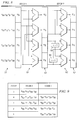
- FIGURE 8 diagrammatically illustrates exemplary embodiments of a data processing apparatus which can perform the first and second stage operations described above with respect to FIGURES 6 and 7.
- the apparatus of FIGURE 8 includes a matrix multiplication apparatus having a matrix multiplier 81 which performs the first stage matrix multiplication operation illustrated in FIGURE 6, and having a matrix multiplier 82 which performs the second stage matrix multiplication operation illustrated in FIGURE 7.
- the first stage matrix multiplier 81 receives the data from the input data matrix 51 and performs the arithmetic operations necessary to produce the intermediate data matrix 61 (see also FIGURE 6).
- the matrix multiplier 81 includes four adders connected appropriately, and with necessary inversions, to perform the four addition operations required to implement the matrix multiplication equation of FIGURE 6.
- the matrix multiplier 82 receives the data from the intermediate matrix 61 and performs the arithmetic operations necessary to produce the transform result matrix 52 (see also FIGURE 7).
- the matrix multiplier 82 includes four adders connected appropriately, and with necessary inversions and shifters, to perform the four addition operations and two shift operations required to implement the matrix multiplication equation of FIGURE 7.
- Data shifters 83 and 84 each perform a single left shift (multiply by 2) operation in order to implement the two multiplication operations required by the equation of FIGURE 7.
- FIGURE 9 illustrates in tabular format the timing of exemplary operations which can be performed by the data processing apparatus of FIGURE 8.
- the data processing apparatus of FIGURE 8 can produce each column of the matrix 61 of FIGURE 6 in a single clock cycle, and can also produce each column of the matrix 52 of FIGURE 7 in a single clock cycle. That is, the adders of the matrix multiplier 81 can effectuate a multiplication of all four rows of the transform matrix 41 by any given column of the input matrix 51 in a single clock cycle, and the adders of the matrix multiplier 82, together with shifters 83 and 84, can effectuate multiplication of all four rows of matrix 42 by any given column of matrix 61 in a single clock cycle.
- the second stage matrix multiplier 82 can use the first column of the intermediate matrix 61 to produce the first column of the transform result matrix 52.
- the matrix multiplier 81 produces the first column (column 0) of the intermediate matrix 61.
- the second stage matrix multiplier 82 is simultaneously using the already-produced first column of intermediate matrix 61 to produce the first column of the transform result matrix 52.
- the operations of the matrix multipliers 81 and 82 can be pipelined as shown in FIGURE 9 in order to produce the complete transform result matrix 52 of FIGURE 7 in five clock cycles. So the data processing apparatus of FIGURE 8 can perform a 4x4 one dimensional integer transform in five clock cycles. As indicated by FIGURE 9, during clock cycle 5, while the second stage matrix multiplier 82 is producing the fourth column (column 3) of the transform result matrix 52 of FIGURE 7, the first stage matrix multiplier 81 can be simultaneously operating on a subsequent input data matrix 51 to produce the first column of a subsequent intermediate data matrix 61 (see also FIGURE 6).
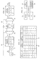
- FIGURE 10 diagrammatically illustrates exemplary embodiments of a data processing apparatus which can perform a 4x4 two dimensional integer transform according to the invention.
- the architecture of FIGURE 8 is used to perform a horizontal transform HT and is also used to perform a vertical transform VT.
- the horizontal transform portion HT performs the operations illustrated in FIGURE 8 to produce the transform result matrix 52.
- This transform result matrix 52 is then stored in one of two buffers 105 and 106, as selected by a selector 103 under control of a control signal 107.
- a further selector 104 under control of a control signal 108 provides the content of one of buffers 105 and 106 to the vertical transform portion VT.
- the buffers 105 and 106 can be read such that the data from the buffered transform result matrix 52 is provided to the vertical transform portion VT on a row-by-row basis, so the vertical transform portion VT operates on the transpose of the buffered transform result matrix 52.
- This effective transposing of the buffered transform result matrix 52 is illustrated in FIGURE 10 by the use of the reference character 52 t . Transposition of the result matrix produced by horizontal transform portion HT permits the vertical transform portion VT to perform the transform in the second dimension.
- FIGURE 11 illustrates in tabular format the timing of exemplary operations which can be performed by the data processing apparatus of FIGURE 10.
- the horizontal transform portion HT completes its operation on the first 4x4 input data matrix 51 (also designated as B 1 ), and stage 1 of the HT portion has also already begun operation on the second 4x4 input data matrix 51 (also designated as B 2 ).
- the vertical transform portion VT can begin operations on the transpose 52 t of the first transform result matrix 52 during clock cycle 6.
- the correspondence of the transposed transform result matrices 52 t to the input data matrices 51 is illustrated in FIGURE 11 by maintaining corresponding subscript numbers on the designators B.
- the selectors 103 and 104 are controlled by logically complementary control signals 107 and 108 such that the vertical transform portion VT is never accessing the buffer to which the horizontal transform portion HT is writing.
- the horizontal transform portion HT is simultaneously processing data from the second input data matrix 51/B 2 in the sequence of input data matrices.
- the horizontal transform portion HT can complete its operation on a sequence of six 4x4 input matrices in 25 clock cycles and, by virtue of the pipelining illustrated in FIGURE 11, the complete two dimensional transform of a sequence of six 4x4 input data matrices is completed in thirty clock cycles.
- the output of the vertical transform portion VT in FIGURE 10 can be provided to a conventional quantization stage for conventional rescaling and quantizing.
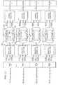
- FIGURE 12 diagrammatically illustrates exemplary embodiments of a data processing apparatus which can perform a plurality of 4x4 two-dimensional integer transforms in parallel according to the invention.
- the example of FIGURE 12 generally uses four instances of the architecture of FIGURE 10, arranged in parallel. Therefore, the apparatus of FIGURE 12 can perform two dimensional transform processing on 24 4x4 input matrices in thirty clock cycles (see also FIGURE 11).
- the twenty four 4x4 input data blocks illustrated in the example of FIGURE 12 are the well-known constituent blocks of a conventional H.264/AVC macroblock. Each of the four 32-bit input registers can hold four 8-bit input pixels.
- FIGURE 13 diagrammatically illustrates exemplary embodiments of a data processing system according to the invention.
- the system of FIGURE 13 for example a high definition television system or a digital cinema system, includes a main processor 131, a memory portion 132, a user interface (I/O) 133 and an accelerator coprocessor 134. These components are interconnected by a bus system 135.
- the accelerator coprocessor 134 can implement the various exemplary integer transform architectures described above with respect to FIGURES 8-12.
- the main processor 131 and the coprocessor 134 implement respective pipelines.
- the coprocessor 134 receives instructions from the main processor 131, and uses a pipeline follower to determine what instruction it must execute. To avoid congestion in the critical path, in some embodiments the coprocessor pipeline operates one clock cycle behind the main processor pipeline. After receiving a given instruction, the coprocessor loads data from the memory and performs the necessary transform operations.
- the main processor 131 is an ARM946E-S processor
- the system memory portion 132 includes 512 kilobytes of SRAM and 4 megabytes of SDRAM
- the bus system 135 is a conventional high speed AMBA bus system for increased data throughput between the main processor 131, the coprocessor 134 and the system memory 132.
- the hardware cost of the illustrated architecture is low. It requires four 32-bit registers, four 64-bit registers, 16 multiplexers, 32 adders and 256 bytes of buffer memory.
- the small buffer memory is implemented with D flip-flops in some embodiments.
- the footprint of the FIGURE 12 architecture is only 0.0838 mm 2 . Even with this small footprint, the architecture still provides sufficient computing power for real time video processing.
- the architecture can compute integer transforms for 2Kx1K (2048x1024) format at 30 frames per second.
- 16:9 format (4096x2034) running at 60 frames per second
- the architecture requires 66,355,200 clock cycles, which is equivalent to 67 MHz.
- the design of the architecture can be scaled to meet this real time constraint.
- the clock rate is 10 MHz
- the global voltage is 1.55 V
- the load capacitance is 1 pf.
- the switching power reported by a hardware simulation for this example is 529 ⁇ W.
- exemplary embodiments of the invention require only a small data range. From FIGURES 5-7, the data range at the output of each stage can be easily determined. In the worst case, and assuming 8-bit pixel inputs, the outputs of the first dimensional transform (e.g. HT in FIGURES 10 and 12) are 11 bits and the outputs of the second dimensional transform (e.g. VT in FIGURES 10 and 12) are 14 bits. Hence, a 4x4 two-dimensional integer transform can be implemented with a 14-bit wide data path.
- the first dimensional transform e.g. HT in FIGURES 10 and 12
- the outputs of the second dimensional transform e.g. VT in FIGURES 10 and 12
- exemplary embodiments of the invention introduce a method and an apparatus to reduce computational complexity and increase the throughput of the integer transform in H.264 video compression standard.
- the method factors the integer transform matrix into two integer matrices with less computations.
- this approach also allows the integer transform be calculated in two steps, which is well suited for pipeline architecture.
Landscapes
- Engineering & Computer Science (AREA)
- Multimedia (AREA)
- Signal Processing (AREA)
- Computing Systems (AREA)
- Theoretical Computer Science (AREA)
- Complex Calculations (AREA)
- Compression Or Coding Systems Of Tv Signals (AREA)
- Compression Of Band Width Or Redundancy In Fax (AREA)
Applications Claiming Priority (4)
| Application Number | Priority Date | Filing Date | Title |
|---|---|---|---|
| US53148903P | 2003-12-19 | 2003-12-19 | |
| US531489P | 2003-12-19 | ||
| US975638 | 2004-10-28 | ||
| US10/975,638 US7756351B2 (en) | 2003-12-19 | 2004-10-28 | Low power, high performance transform coprocessor for video compression |
Publications (2)
| Publication Number | Publication Date |
|---|---|
| EP1544797A2 true EP1544797A2 (fr) | 2005-06-22 |
| EP1544797A3 EP1544797A3 (fr) | 2009-04-01 |
Family
ID=34527154
Family Applications (1)
| Application Number | Title | Priority Date | Filing Date |
|---|---|---|---|
| EP04257767A Withdrawn EP1544797A3 (fr) | 2003-12-19 | 2004-12-14 | Coprocesseur de calcul d'une transformation pour la compression vidéo à haute performance et à faible consommation d'énergie |
Country Status (3)
| Country | Link |
|---|---|
| US (1) | US7756351B2 (fr) |
| EP (1) | EP1544797A3 (fr) |
| JP (1) | JP2005184829A (fr) |
Cited By (2)
| Publication number | Priority date | Publication date | Assignee | Title |
|---|---|---|---|---|
| WO2009042943A3 (fr) * | 2007-09-26 | 2010-12-29 | Qualcomm Incorporated | Techniques de transformation efficaces pour le codage vidéo |
| RU2595592C2 (ru) * | 2010-12-28 | 2016-08-27 | Сан Пэтент Траст | Способ декодирования движущегося изображения, способ кодирования движущегося изображения, устройство декодирования движущегося изображения, устройство кодирования движущегося изображения и устройство кодирования и декодирования движущегося изображения |
Families Citing this family (7)
| Publication number | Priority date | Publication date | Assignee | Title |
|---|---|---|---|---|
| KR100711088B1 (ko) * | 2005-04-13 | 2007-04-24 | 광주과학기술원 | 동화상 인코더를 위한 정수 변환 장치 |
| KR101982819B1 (ko) | 2010-09-28 | 2019-05-28 | 삼성전자주식회사 | 비디오의 부호화 방법 및 장치, 복호화 방법 및 장치 |
| US9241163B2 (en) * | 2013-03-15 | 2016-01-19 | Intersil Americas LLC | VC-2 decoding using parallel decoding paths |
| US9098449B2 (en) * | 2013-03-15 | 2015-08-04 | Analog Devices, Inc. | FFT accelerator |
| US9426434B1 (en) | 2014-04-21 | 2016-08-23 | Ambarella, Inc. | Two-dimensional transformation with minimum buffering |
| CA2959023C (fr) * | 2014-08-22 | 2023-01-10 | Nova Southeastern University | Compression adaptative de donnees et chiffrement de donnees a l'aide de produits de kronecker |
| US20220094984A1 (en) * | 2021-12-06 | 2022-03-24 | Atthar Mohammed | Unrestricted intra content to improve video quality of real-time encoding |
Citations (6)
| Publication number | Priority date | Publication date | Assignee | Title |
|---|---|---|---|---|
| US4791598A (en) * | 1987-03-24 | 1988-12-13 | Bell Communications Research, Inc. | Two-dimensional discrete cosine transform processor |
| US5523847A (en) | 1992-10-09 | 1996-06-04 | International Business Machines Corporation | Digital image processor for color image compression |
| US6185595B1 (en) | 1995-06-01 | 2001-02-06 | Hitachi, Ltd. | Discrete cosine transformation operation circuit |
| US20020124035A1 (en) | 2000-12-01 | 2002-09-05 | Vance Faber | Method for lossless encoding of image data by approximating linear transforms and preserving selected properties for image processing |
| WO2003019787A2 (fr) | 2001-08-30 | 2003-03-06 | Nokia Corporation | Mise en oeuvre d'une transformee et d'une quantification subsequente |
| US20030099291A1 (en) | 2001-08-09 | 2003-05-29 | Kerofsky Louis J. | Systems and methods for enabling reduced bit-depth processing and memory reduction in video-related data processing |
Family Cites Families (1)
| Publication number | Priority date | Publication date | Assignee | Title |
|---|---|---|---|---|
| WO2000010320A2 (fr) * | 1998-08-13 | 2000-02-24 | Equator Technologies, Inc. | Circuit et procede de realisation d'une transformee bidimensionnelle pendant le traitement d'une image |
-
2004
- 2004-10-28 US US10/975,638 patent/US7756351B2/en not_active Expired - Fee Related
- 2004-12-14 EP EP04257767A patent/EP1544797A3/fr not_active Withdrawn
- 2004-12-17 JP JP2004365275A patent/JP2005184829A/ja active Pending
Patent Citations (6)
| Publication number | Priority date | Publication date | Assignee | Title |
|---|---|---|---|---|
| US4791598A (en) * | 1987-03-24 | 1988-12-13 | Bell Communications Research, Inc. | Two-dimensional discrete cosine transform processor |
| US5523847A (en) | 1992-10-09 | 1996-06-04 | International Business Machines Corporation | Digital image processor for color image compression |
| US6185595B1 (en) | 1995-06-01 | 2001-02-06 | Hitachi, Ltd. | Discrete cosine transformation operation circuit |
| US20020124035A1 (en) | 2000-12-01 | 2002-09-05 | Vance Faber | Method for lossless encoding of image data by approximating linear transforms and preserving selected properties for image processing |
| US20030099291A1 (en) | 2001-08-09 | 2003-05-29 | Kerofsky Louis J. | Systems and methods for enabling reduced bit-depth processing and memory reduction in video-related data processing |
| WO2003019787A2 (fr) | 2001-08-30 | 2003-03-06 | Nokia Corporation | Mise en oeuvre d'une transformee et d'une quantification subsequente |
Cited By (3)
| Publication number | Priority date | Publication date | Assignee | Title |
|---|---|---|---|---|
| WO2009042943A3 (fr) * | 2007-09-26 | 2010-12-29 | Qualcomm Incorporated | Techniques de transformation efficaces pour le codage vidéo |
| US8654833B2 (en) | 2007-09-26 | 2014-02-18 | Qualcomm Incorporated | Efficient transformation techniques for video coding |
| RU2595592C2 (ru) * | 2010-12-28 | 2016-08-27 | Сан Пэтент Траст | Способ декодирования движущегося изображения, способ кодирования движущегося изображения, устройство декодирования движущегося изображения, устройство кодирования движущегося изображения и устройство кодирования и декодирования движущегося изображения |
Also Published As
| Publication number | Publication date |
|---|---|
| EP1544797A3 (fr) | 2009-04-01 |
| US20050141776A1 (en) | 2005-06-30 |
| JP2005184829A (ja) | 2005-07-07 |
| US7756351B2 (en) | 2010-07-13 |
Similar Documents
| Publication | Publication Date | Title |
|---|---|---|
| US6587590B1 (en) | Method and system for computing 8×8 DCT/IDCT and a VLSI implementation | |
| EP1359546A1 (fr) | Transformations bidimensionelles pour le codage d'images ou de vidéos | |
| Masera et al. | Adaptive approximated DCT architectures for HEVC | |
| US9665540B2 (en) | Video decoder with a programmable inverse transform unit | |
| Masaki et al. | VLSI implementation of inverse discrete cosine transformer and motion compensator for MPEG2 HDTV video decoding | |
| US20100321579A1 (en) | Front End Processor with Extendable Data Path | |
| Amish et al. | Fully pipelined real time hardware solution for High Efficiency Video Coding (HEVC) intra prediction | |
| JP2002531973A (ja) | 画像の圧縮及び伸張 | |
| Ben Atitallah et al. | An FPGA comparative study of high‐level and low‐level combined designs for HEVC intra, inverse quantization, and IDCT/IDST 2D modules | |
| US7756351B2 (en) | Low power, high performance transform coprocessor for video compression | |
| Saponara | Real-time and low-power processing of 3D direct/inverse discrete cosine transform for low-complexity video codec | |
| US20020021842A1 (en) | Circuit and method for performing a two-dimensional transform during the processing of an image | |
| Dias et al. | Unified transform architecture for AVC, AVS, VC-1 and HEVC high-performance codecs | |
| Sun et al. | VLSI implementation of a configurable IP Core for quantized discrete cosine and integer transforms | |
| Dias et al. | High performance multi-standard architecture for DCT computation in H. 264/AVC high profile and HEVC codecs | |
| US20060129622A1 (en) | Method and system for fast implementation of an approximation of a discrete cosine transform | |
| Joshi et al. | Efficient large size transforms for high-performance video coding | |
| JP4704333B2 (ja) | 画像符号化装置および画像復号化装置、ならびにそれらで用いられる集積回路 | |
| Chang et al. | A fast algorithm-based cost-effective and hardware-efficient unified architecture design of 4× 4, 8× 8, 16× 16, and 32× 32 inverse core transforms for HEVC | |
| Hatim et al. | Efficient architecture for direct 8× 8 2D DCT computations with earlier zigzag ordering | |
| Shen et al. | A unified forward/inverse transform architecture for multi-standard video codec design | |
| Dang et al. | BinDCT and its efficient VLSI architectures for real-time embedded applications | |
| Loukil et al. | A novel architecture design for VLSI implementation of integer DCT in HEVC standard | |
| Atitallah et al. | Advanced design of TQ/IQT component for H. 264/AVC based on SoPC validation | |
| Yang et al. | An efficient two-dimensional inverse discrete cosine transform algorithm for HDTV receivers |
Legal Events
| Date | Code | Title | Description |
|---|---|---|---|
| PUAI | Public reference made under article 153(3) epc to a published international application that has entered the european phase |
Free format text: ORIGINAL CODE: 0009012 |
|
| AK | Designated contracting states |
Kind code of ref document: A2 Designated state(s): AT BE BG CH CY CZ DE DK EE ES FI FR GB GR HU IE IS IT LI LT LU MC NL PL PT RO SE SI SK TR |
|
| AX | Request for extension of the european patent |
Extension state: AL BA HR LV MK YU |
|
| PUAL | Search report despatched |
Free format text: ORIGINAL CODE: 0009013 |
|
| AK | Designated contracting states |
Kind code of ref document: A3 Designated state(s): AT BE BG CH CY CZ DE DK EE ES FI FR GB GR HU IE IS IT LI LT LU MC NL PL PT RO SE SI SK TR |
|
| AX | Request for extension of the european patent |
Extension state: AL BA HR LV MK YU |
|
| RIC1 | Information provided on ipc code assigned before grant |
Ipc: H04N 7/26 20060101ALI20090223BHEP Ipc: G06T 9/00 20060101AFI20050218BHEP |
|
| 17P | Request for examination filed |
Effective date: 20090923 |
|
| 17Q | First examination report despatched |
Effective date: 20091019 |
|
| AKX | Designation fees paid |
Designated state(s): DE FR GB IT |
|
| RAP1 | Party data changed (applicant data changed or rights of an application transferred) |
Owner name: STMICROELECTRONICS, INC. |
|
| STAA | Information on the status of an ep patent application or granted ep patent |
Free format text: STATUS: THE APPLICATION IS DEEMED TO BE WITHDRAWN |
|
| 18D | Application deemed to be withdrawn |
Effective date: 20150228 |