EP1544698B1 - Dispositif et méthode pour contrôler un réseau d'énergie électrique - Google Patents
Dispositif et méthode pour contrôler un réseau d'énergie électrique Download PDFInfo
- Publication number
- EP1544698B1 EP1544698B1 EP20030104858 EP03104858A EP1544698B1 EP 1544698 B1 EP1544698 B1 EP 1544698B1 EP 20030104858 EP20030104858 EP 20030104858 EP 03104858 A EP03104858 A EP 03104858A EP 1544698 B1 EP1544698 B1 EP 1544698B1
- Authority
- EP
- European Patent Office
- Prior art keywords
- power supply
- supply system
- prediction
- vehicle power
- vehicle
- Prior art date
- Legal status (The legal status is an assumption and is not a legal conclusion. Google has not performed a legal analysis and makes no representation as to the accuracy of the status listed.)
- Expired - Lifetime
Links
- 238000000034 method Methods 0.000 title claims description 35
- 239000013598 vector Substances 0.000 claims description 48
- 230000008859 change Effects 0.000 claims description 5
- 238000001514 detection method Methods 0.000 claims description 5
- 239000011159 matrix material Substances 0.000 claims description 4
- 238000004519 manufacturing process Methods 0.000 claims description 3
- 238000012544 monitoring process Methods 0.000 claims 1
- 230000006870 function Effects 0.000 description 10
- 238000004422 calculation algorithm Methods 0.000 description 7
- 238000005259 measurement Methods 0.000 description 7
- 238000012360 testing method Methods 0.000 description 6
- 238000004364 calculation method Methods 0.000 description 5
- 230000000875 corresponding effect Effects 0.000 description 5
- 230000001276 controlling effect Effects 0.000 description 4
- 238000002485 combustion reaction Methods 0.000 description 3
- 230000006978 adaptation Effects 0.000 description 2
- 230000003044 adaptive effect Effects 0.000 description 2
- 238000005070 sampling Methods 0.000 description 2
- 238000004458 analytical method Methods 0.000 description 1
- 230000008901 benefit Effects 0.000 description 1
- 238000010276 construction Methods 0.000 description 1
- 230000002596 correlated effect Effects 0.000 description 1
- 238000009795 derivation Methods 0.000 description 1
- 238000011161 development Methods 0.000 description 1
- 230000018109 developmental process Effects 0.000 description 1
- 238000011156 evaluation Methods 0.000 description 1
- 238000000605 extraction Methods 0.000 description 1
- 238000011068 loading method Methods 0.000 description 1
- 238000012986 modification Methods 0.000 description 1
- 230000004048 modification Effects 0.000 description 1
- 238000003909 pattern recognition Methods 0.000 description 1
- 238000012545 processing Methods 0.000 description 1
- 230000009466 transformation Effects 0.000 description 1
- 230000017105 transposition Effects 0.000 description 1
Images


Classifications
-
- B—PERFORMING OPERATIONS; TRANSPORTING
- B60—VEHICLES IN GENERAL
- B60R—VEHICLES, VEHICLE FITTINGS, OR VEHICLE PARTS, NOT OTHERWISE PROVIDED FOR
- B60R16/00—Electric or fluid circuits specially adapted for vehicles and not otherwise provided for; Arrangement of elements of electric or fluid circuits specially adapted for vehicles and not otherwise provided for
- B60R16/02—Electric or fluid circuits specially adapted for vehicles and not otherwise provided for; Arrangement of elements of electric or fluid circuits specially adapted for vehicles and not otherwise provided for electric constitutive elements
- B60R16/023—Electric or fluid circuits specially adapted for vehicles and not otherwise provided for; Arrangement of elements of electric or fluid circuits specially adapted for vehicles and not otherwise provided for electric constitutive elements for transmission of signals between vehicle parts or subsystems
-
- B—PERFORMING OPERATIONS; TRANSPORTING
- B62—LAND VEHICLES FOR TRAVELLING OTHERWISE THAN ON RAILS
- B62D—MOTOR VEHICLES; TRAILERS
- B62D5/00—Power-assisted or power-driven steering
- B62D5/04—Power-assisted or power-driven steering electrical, e.g. using an electric servo-motor connected to, or forming part of, the steering gear
- B62D5/0457—Power-assisted or power-driven steering electrical, e.g. using an electric servo-motor connected to, or forming part of, the steering gear characterised by control features of the drive means as such
- B62D5/0481—Power-assisted or power-driven steering electrical, e.g. using an electric servo-motor connected to, or forming part of, the steering gear characterised by control features of the drive means as such monitoring the steering system, e.g. failures
Definitions
- the invention relates to a method for predicting a future load condition in the electrical system of a motor vehicle and to a method and a device for controlling the electrical system of a motor vehicle.
- Modern motor vehicles are characterized by an increasing number of electrical and electronic devices, which must be powered by the electrical system of the motor vehicle with energy.
- Certain consumers such as an electric steering assistance system - often cause problems, as they can temporarily cause very high peak loads in the electrical system, which exceed the current capacity of the electrical system.
- a controller for an electric power steering for a motor vehicle is known.
- the controller is configured to predict a decrease in the supply voltage of a power steering motor and to perform an idle speed increase when a decrease in the supply voltage is predicted.
- DE 193 18 505 A1 discloses an electronic power steering system and method in which vehicle operating parameters are used to predict future power requirements of the power steering system. Based on these predicted power requirements, vehicle operating parameters, such as the engine and an alternator system, are adjusted to ensure proper power supply to the power steering system without voltage spikes or voltage dips.
- Object of the present invention was therefore to provide alternative means by which the functionality of the electrical system of a motor vehicle can be ensured as continuously as possible.
- the method enables the prediction of future loadings of the on-board network on the basis of currently measured parameter vectors, wherein the predictive model is empirically derived from example data. It is not necessary to know or analyze functional relationships between operating parameters of the motor vehicle and future power consumption. Rather, such relationships are extracted from the example data by an adaptation method and converted into a prediction zone subdivision of the parameter space. The predictions about the future load obtained by the method can be used to advantage To counteract exceeding the capacity limits of the electrical system and thereby ensure a continuous functioning of the network.
- a load state of the electrical system can be defined by the fact that within a given future period of the current flow in the electrical system or in a particular consumer on the electrical system is at least temporarily in a predetermined interval. For example, by specifying the current interval [ ⁇ , ⁇ [exactly two load states can be distinguished, namely the remaining of the current below the threshold ⁇ or the exceeding of this threshold within the next ⁇ seconds after the time in question. By specifying a plurality of such thresholds, in principle any number of load states can be differentiated.
- the parameter vector may contain at least one of the variables enumerated below and / or at least one (single or multiple) time derivative thereof: the current flow in the electrical system or in a specific consumer on the electrical system; the rate of change of the current flow in the electrical system or in a specific consumer on the electrical system; the vehicle speed; the steering angle and / or the rate of change of the steering angle, which quantities are particularly important with regard to power peaks of an electric steering assistance; the accelerator pedal position; Road parameters such as upcoming branches, gradients or curves, where the road parameters may be provided by a navigation system; the state of the turn signal to the direction indicator, which size may be important for the display of upcoming steering maneuvers of importance.
- a prediction zone can be characterized or defined by statistical characteristics of the respectively associated subset of the example data.
- the subset of the example data associated with a prediction zone comprises all the example data whose load state corresponds to the load state associated with the prediction zone.
- the total amount of all the sample data is divided into subsets, each characterized by a particular load condition, and within the subsets, statistical measures are then determined to define corresponding prediction zones.
- the above-mentioned statistical parameters may in particular be the mean value ⁇ and the covariance matrix ⁇ of all the parameter vectors of the respective subset.
- the mean value describes a characteristic or representative point of the respective subset, while the covariance detects correlations between the components of the parameter vectors.
- the above-mentioned statistical characteristics of the mean value and the covariance can be used in particular as follows for the definition of the prediction zones or for the assignment of a current parameter vector S (t):
- An (arbitrary or current) parameter vector S is assigned to that prediction zone to which it is assigned has the shortest Mahalanobis distance, where the Mahalanobis distance is defined as the size ( S- ⁇ ) T ⁇ -1 ( S- ⁇ ).
- the Mahalanobis distance is defined as the size ( S- ⁇ ) T ⁇ -1 ( S- ⁇ ).
- step a) of the method and the subdivision of the space of the parameter vectors into prediction zones can be carried out separately, ie uniformly and driver-independently for a large number of vehicles. However, it is preferably carried out while driving a motor vehicle, so that the example data specific to the individual motor vehicle and the driver and, if necessary, can also adapt to changes over time.
- the method can ensure that impending load peaks do not lead to an overload of the vehicle electrical system.
- the invention further relates to a device for controlling the electrical system of a motor vehicle, which is designed to carry out a method of the type described above.
- the device can be realized, in particular, by a data processing device (microcontroller, etc.) which is equipped with corresponding signal inputs for detecting a parameter vector and optionally with control outputs for controlling the power consumption of consumers or the power production of generators.
- a data processing device microcontroller, etc.
- the electrical system controlled by the device can be an electric steering assist system, an electric compressor for the internal combustion engine and / or a fan for the internal combustion engine included.
- These components are devices which are characterized by consumption with peak loads, so that a forward-looking management of the electrical system is particularly important for this purpose.
- FIG. 1 shows a typical time profile of the current consumption I of an electric power assisted steering system (EPAS) of a motor vehicle. While the power consumption averaged over the travel time of such a system is relatively low, the course again and again has very short current peaks of up to 100 A. Such current peaks can pose a problem for the stability of the electrical system of the motor vehicle. Therefore, in the present case, a method is proposed in which situations are detected in advance based on a statistical pattern recognition in which a steering assist system or other system such as an electrically driven diesel compressor (EDC) or a fan motor for an internal combustion engine lead to current spikes. Based on this prediction, a control device for the vehicle electrical system can then react accordingly in order to avoid exceeding the capacities of the electrical system and high fluctuations of the voltage.
- EDC electrically driven diesel compressor
- control device can reduce the power consumption of less critical consumers such as heaters for a short time, delay or switch off.
- control device can also drive up the power supply by a generator (alternator, etc.) in order to guarantee the provision of sufficient power.
- a (future) load state of the vehicle electrical system is represented as an (EPAS) current peak of more than ⁇ A within the next ⁇ seconds, ie in the time interval [t, t + ⁇ ], defined.
- the first component S 1 (t) of the parameter vector should be the instantaneous value of the EPAS current flow.
- CPD ⁇ . ⁇ ( S ( t ) ) 0 . if no current peak is detected ,
- FIG. 3 shows the correct prediction function (lower bar) for test data of the current profile I analogous to FIG. 2, as well as the prediction of a calculated prediction function CPD ⁇ , ⁇ (upper bar). Deviations between the two bars represent the prediction errors and therefore contribute to the percentages p 01 and p 10, respectively. These percentages can be used as the first quality measure for the calculated predictive function.
- E 2 can be regarded as the error rate, the minimization of which is more important since it corresponds to the undetected and thus untreated current peaks, while the errors underlying E 1 can "only" lead to superfluous control actions in the electrical system.
- test data When judging a prediction function obtained according to the first step from "test data”, care should be taken that the learning data and the test data are different, since good predictions on the learning data are a necessary condition, but a poor measure of the generalization ability , In this sense, nine sets of test data, each corresponding to a driver's data, were generated from the total measurement data explained above, with the associated learning data being constituted by the data of the remaining drivers.
- the value of the searched prediction function CPD ⁇ , ⁇ for a current parameter vector S (t) can be calculated according to the following symbolically notated algorithm:
- T denotes the transposition of a vector and "-1" the inversion of a matrix.
- the described algorithm can be implemented quickly and easily.
- the influence of the quantities ⁇ and ⁇ , which define the load state, is indirect because it influences the division of the example data into the sub-sets G 0 and G 1 and thus the statistical parameters derived therefrom.
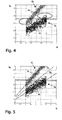
- FIG. 4 shows in this respect a typical distribution of two components S i , S k of the parameter vectors of example data (crosses). Immediately recognizable is that the sample data is distributed over two clusters which correspond to subsets G 0 (no subsequent load condition observed) and G 1 (subsequent load condition observed). Because a correlation of the vector components S i, S k, the cluster have an elongated shape, respectively, wherein the mean values ⁇ 0 and ⁇ 1 in the center of the cluster G 0 and G 1 are.
- the "Mahalanobis decision boundary" is entered as a dashed line, which divides the parameter plane into the two prediction zones (half planes) V 0 and V 1 and which lies exactly between the named axes, which greatly prevents misclassifications. Points lying on the decision boundary itself can, for example, be assigned to the zone V 0 by definition.
- the tendency indicated herein can be confirmed by a complete analysis of the weighted averages of E 1 and E 2 in that the quality of the prediction algorithm increases with an increase in ⁇ and / or with a decrease in ⁇ .
- cov n (S i , S j ) means the covariance between S i and S j after n measurements and ⁇ i (n-1) for the mean value of the signal S i after the first (n-1) measurements.
- more than two load states or more than two prediction zones could be considered.
- the occurrence of one of the following m events could be predicted: “no current spike”, “current spike between ⁇ 1 A and ⁇ 2 A”, ..., “current spike between ⁇ m-1 A, and ⁇ m A” in the next ⁇ seconds.
- This is a direct generalization of the method described above, wherein only m different subsets need to be defined, the corresponding number of parameters (mean vectors and covariance matrices) must be calculated, and the decision must be extended to the calculation of the minimum of m distances ,
Landscapes
- Engineering & Computer Science (AREA)
- Mechanical Engineering (AREA)
- Chemical & Material Sciences (AREA)
- Combustion & Propulsion (AREA)
- Transportation (AREA)
- Control Of Electric Motors In General (AREA)
- Feedback Control In General (AREA)
Claims (8)
- Procédé pour prédire un futur état de charge du réseau de bord d'un véhicule automobile à l'aide de vecteurs de paramètres qui contiennent les paramètres de fonctionnement caractéristiques du véhicule automobile, comprenant les étapes :a) Division de l'espace des vecteurs de paramètres (S) en zones de prédiction (V0, V1), différents états de charge du réseau de bord étant associés aux zones de prédiction et la division étant obtenue par adaptation au moyen d'exemples de données (G0, G1) des vecteurs de paramètres mesurés et des états de charge correspondants du réseau de bord ;b) Acquisition du vecteur de paramètre correspondant à un instant actuel (t) ;c) détermination de la zone de prédiction (V0, V1) dans laquelle se trouve le paramètre de vecteur actuel et utilisation de l'état de charge qui lui est associé comme prédiction du futur état de charge du réseau de bord.
- Procédé selon la revendication 1, caractérisé en ce que l'état de charge du réseau de bord est caractérisé en ce qu'au sien d'une période future prédéfinie ([t, t+π]), le flux de courant (I) dans le réseau de bord ou dans une charge donnée du réseau de bord se trouve au moins temporairement dans un intervalle prédéfini ([Θ, ∞]).
- Procédé selon la revendication 1 ou 2, caractérisé en ce que le vecteur de paramètre (S) contient au moins l'une des grandeurs suivantes et/ou au moins une dérivée dans le temps de celle-ci : le flux de courant (I) dans le réseau de bord ou dans une charge donnée du réseau de bord ; le taux de variation du flux de courant dans le réseau de bord ou dans une charge donnée du réseau de bord ; la vitesse du véhicule ; l'angle de direction ; le taux de variation de l'angle de direction ; la position de la pédale des gaz ; un paramètre de la route provenant d'un système de navigation ; l'état de la centrale clignotante.
- Procédé selon l'une des revendications 1 à 3, caractérisé en ce que les zones de prédiction (V0, V1) sont caractérisées par des grandeurs caractéristiques statistiques du sous-ensemble (G0, G1) correspondant.
- Procédé selon la revendication 4, caractérisé en ce que les grandeurs caractéristiques statistiques comprennent la valeur moyenne µ correspondante et la matrice de covariance Σ correspondante du sous-ensemble (G0, G1) .
- Procédé selon la revendication 5, caractérisé en ce qu'un vecteur de paramètre actuel S(t) est associé à la zone de prédiction (V0, V1) par rapport à laquelle il présente la distance de Mahalanobis la plus courte, laquelle est définie sous la forme (S-µ)T Σ-1 (S-µ).
- Procédé selon l'une des revendications 1 à 6, caractérisé en ce que l'étape a) ainsi que l'acquisition des exemples de données est exécutée pendant le déplacement d'un véhicule automobile.
- Procédé de contrôle du réseau de bord d'un véhicule automobile, caractérisé par les étapesa) Prédiction d'un futur état de charge du réseau de bord avec un procédé selon au moins l'une des revendications 1 à 7 ;b) Contrôle de la puissance consommée par les charges et/ou de la puissance produite par les générateurs de telle sorte que l'état de charge prédit se trouve dans la plage de capacité du réseau de bord.
Priority Applications (2)
| Application Number | Priority Date | Filing Date | Title |
|---|---|---|---|
| DE50305439T DE50305439D1 (de) | 2003-12-19 | 2003-12-19 | Vorrichtung und Verfahren zur Kontrolle eines Bordnetzes |
| EP20030104858 EP1544698B1 (fr) | 2003-12-19 | 2003-12-19 | Dispositif et méthode pour contrôler un réseau d'énergie électrique |
Applications Claiming Priority (1)
| Application Number | Priority Date | Filing Date | Title |
|---|---|---|---|
| EP20030104858 EP1544698B1 (fr) | 2003-12-19 | 2003-12-19 | Dispositif et méthode pour contrôler un réseau d'énergie électrique |
Publications (2)
| Publication Number | Publication Date |
|---|---|
| EP1544698A1 EP1544698A1 (fr) | 2005-06-22 |
| EP1544698B1 true EP1544698B1 (fr) | 2006-10-18 |
Family
ID=34486408
Family Applications (1)
| Application Number | Title | Priority Date | Filing Date |
|---|---|---|---|
| EP20030104858 Expired - Lifetime EP1544698B1 (fr) | 2003-12-19 | 2003-12-19 | Dispositif et méthode pour contrôler un réseau d'énergie électrique |
Country Status (2)
| Country | Link |
|---|---|
| EP (1) | EP1544698B1 (fr) |
| DE (1) | DE50305439D1 (fr) |
Families Citing this family (5)
| Publication number | Priority date | Publication date | Assignee | Title |
|---|---|---|---|---|
| DE102006038675A1 (de) * | 2006-08-17 | 2008-03-06 | Bayerische Motoren Werke Ag | Energiemanagementvorrichtung für ein Kraftfahrzeug |
| FR2905646B1 (fr) * | 2006-09-13 | 2008-12-05 | Renault Sas | Systeme et procede de gestion du fonctionnement d'un ensemble moteur-alternateur |
| JP4333743B2 (ja) | 2007-01-10 | 2009-09-16 | トヨタ自動車株式会社 | 操舵装置 |
| LU101181B1 (de) * | 2019-04-12 | 2020-10-12 | Compredict Gmbh | Verfahren zur Bestimmung einer Belastungsvorhersage für ein Bauteil eines Kraftfahrzeugs |
| CN110097297B (zh) * | 2019-05-21 | 2023-08-22 | 国网湖南省电力有限公司 | 一种多维度窃电态势智能感知方法、系统、设备及介质 |
Family Cites Families (2)
| Publication number | Priority date | Publication date | Assignee | Title |
|---|---|---|---|---|
| JP3951337B2 (ja) * | 1997-02-25 | 2007-08-01 | 日本精工株式会社 | 電動パワーステアリング装置の制御装置 |
| US6647330B1 (en) * | 2002-04-30 | 2003-11-11 | Visteon Global Technologies, Inc. | Electronic power assisted steering system and method |
-
2003
- 2003-12-19 EP EP20030104858 patent/EP1544698B1/fr not_active Expired - Lifetime
- 2003-12-19 DE DE50305439T patent/DE50305439D1/de not_active Expired - Lifetime
Also Published As
| Publication number | Publication date |
|---|---|
| DE50305439D1 (de) | 2006-11-30 |
| EP1544698A1 (fr) | 2005-06-22 |
Similar Documents
| Publication | Publication Date | Title |
|---|---|---|
| EP2509828B1 (fr) | Procédé et boîtier de commande pour la détermination du type d'une collision d'un véhicule | |
| DE102008027591B4 (de) | Fahrzeugelektroniksteuerung | |
| EP1259941B1 (fr) | Procede et dispositif pour determiner la duree de vie residuelle d'un produit | |
| DE3603336C2 (fr) | ||
| EP2064522B1 (fr) | Procédé et dispositif destiné à surveiller le bruit d'un capteur | |
| EP2258939B1 (fr) | Procédé de réglage de la température d'une bougie de préchauffage | |
| EP2593754B1 (fr) | Procédé de détection d'une position de commutation d'un dispositif de commutation | |
| DE102014206292B4 (de) | Elektroniksteuervorrichtung | |
| EP3649033B1 (fr) | Procédé pour l'analyse d'un comportement fonctionnel d'un composant d'une installation technique, programme informatique et support d'enregistrement lisible par ordinateur | |
| EP1947623A1 (fr) | Procédé et dispositif destinés à la classification dynamique d'objets et/ou de situations de trafic | |
| EP1544698A1 (fr) | Dispositif et méthode pour contrôler un réseau d'énergie électrique | |
| EP3460727A1 (fr) | Procédé d'analyse d'un comportement fonctionnel d'un système technique et unité d'évaluation | |
| DE10345948B4 (de) | Verfahren zur Bewertung und zeitlichen Stabilisierung von Klassifizierungsergebnissen | |
| WO2005124713A1 (fr) | Procede et dispositif pour detecter la fatigue chez un conducteur de vehicule | |
| DE102010055597A1 (de) | Verfahren und Vorrichtung zum Bestimmen eines Parameters einer Fahrzeugbatterie, insbesondere einer Lithium-Ionen-Batterie | |
| DE102019213835A1 (de) | Verfahren und Vorrichtung zum Erkennen eines zusätzlichen Verbrauchers in einem Energienetz | |
| DE102021103121A1 (de) | Verfahren und Vorrichtungen zur Detektion eines Lichtbogens | |
| EP2105341B1 (fr) | Dispositif d'alimentation en énergie pour un véhicule | |
| DE102010003317B4 (de) | Verfahren und Vorrichtung zur Kombination von Sensordaten für eine Klassifizierung einer Kollision eines Fahrzeugs | |
| EP1889754B1 (fr) | Procédé et dispositif destinés à commander des moyens de protection des personnes et produit de programme informatique | |
| DE102006048907A1 (de) | Verfahren und Vorrichtung zur Ansteuerung von Personenschutzmitteln sowie ein entsprechendes Computerprogramm und Computerprogrammprodukt | |
| DE102021201628B4 (de) | Computerimplementiertes Verfahren und Vorrichtung zur Codierung und Verarbeitung von hochdimensionalen Sensorpfaddaten einer Sensoreinheit zur Steuerung eines Fahrzeugs | |
| DE102021205161B4 (de) | Verfahren und Steuergerät zum Bestimmen einer Maximalstromgrenze eines Batteriesystems mit mindestens zwei Batterien | |
| EP1922217B1 (fr) | Procede d'amelioration d'un systeme de surveillance de la pression des pneus a mesure indirecte | |
| DE102007011277B4 (de) | Verfahren und Vorrichtung zur Sitzüberwachung |
Legal Events
| Date | Code | Title | Description |
|---|---|---|---|
| PUAI | Public reference made under article 153(3) epc to a published international application that has entered the european phase |
Free format text: ORIGINAL CODE: 0009012 |
|
| AK | Designated contracting states |
Kind code of ref document: A1 Designated state(s): AT BE BG CH CY CZ DE DK EE ES FI FR GB GR HU IE IT LI LU MC NL PT RO SE SI SK TR |
|
| AX | Request for extension of the european patent |
Extension state: AL LT LV MK |
|
| 17P | Request for examination filed |
Effective date: 20051222 |
|
| AKX | Designation fees paid |
Designated state(s): DE FR GB |
|
| GRAP | Despatch of communication of intention to grant a patent |
Free format text: ORIGINAL CODE: EPIDOSNIGR1 |
|
| GRAS | Grant fee paid |
Free format text: ORIGINAL CODE: EPIDOSNIGR3 |
|
| GRAA | (expected) grant |
Free format text: ORIGINAL CODE: 0009210 |
|
| AK | Designated contracting states |
Kind code of ref document: B1 Designated state(s): DE FR GB |
|
| REG | Reference to a national code |
Ref country code: GB Ref legal event code: FG4D Free format text: NOT ENGLISH |
|
| REF | Corresponds to: |
Ref document number: 50305439 Country of ref document: DE Date of ref document: 20061130 Kind code of ref document: P |
|
| GBT | Gb: translation of ep patent filed (gb section 77(6)(a)/1977) |
Effective date: 20070129 |
|
| ET | Fr: translation filed | ||
| PLBE | No opposition filed within time limit |
Free format text: ORIGINAL CODE: 0009261 |
|
| STAA | Information on the status of an ep patent application or granted ep patent |
Free format text: STATUS: NO OPPOSITION FILED WITHIN TIME LIMIT |
|
| 26N | No opposition filed |
Effective date: 20070719 |
|
| REG | Reference to a national code |
Ref country code: FR Ref legal event code: PLFP Year of fee payment: 13 |
|
| PGFP | Annual fee paid to national office [announced via postgrant information from national office to epo] |
Ref country code: GB Payment date: 20151125 Year of fee payment: 13 |
|
| PGFP | Annual fee paid to national office [announced via postgrant information from national office to epo] |
Ref country code: FR Payment date: 20151124 Year of fee payment: 13 |
|
| PGFP | Annual fee paid to national office [announced via postgrant information from national office to epo] |
Ref country code: DE Payment date: 20151230 Year of fee payment: 13 |
|
| REG | Reference to a national code |
Ref country code: DE Ref legal event code: R119 Ref document number: 50305439 Country of ref document: DE |
|
| GBPC | Gb: european patent ceased through non-payment of renewal fee |
Effective date: 20161219 |
|
| REG | Reference to a national code |
Ref country code: FR Ref legal event code: ST Effective date: 20170831 |
|
| PG25 | Lapsed in a contracting state [announced via postgrant information from national office to epo] |
Ref country code: FR Free format text: LAPSE BECAUSE OF NON-PAYMENT OF DUE FEES Effective date: 20170102 |
|
| PG25 | Lapsed in a contracting state [announced via postgrant information from national office to epo] |
Ref country code: GB Free format text: LAPSE BECAUSE OF NON-PAYMENT OF DUE FEES Effective date: 20161219 Ref country code: DE Free format text: LAPSE BECAUSE OF NON-PAYMENT OF DUE FEES Effective date: 20170701 |