EP1544604B1 - Verfahren zur Wellenlängenmodulationsspektroskopie - Google Patents
Verfahren zur Wellenlängenmodulationsspektroskopie Download PDFInfo
- Publication number
- EP1544604B1 EP1544604B1 EP03029102.5A EP03029102A EP1544604B1 EP 1544604 B1 EP1544604 B1 EP 1544604B1 EP 03029102 A EP03029102 A EP 03029102A EP 1544604 B1 EP1544604 B1 EP 1544604B1
- Authority
- EP
- European Patent Office
- Prior art keywords
- ref
- meas
- light
- gas
- detector output
- Prior art date
- Legal status (The legal status is an assumption and is not a legal conclusion. Google has not performed a legal analysis and makes no representation as to the accuracy of the status listed.)
- Expired - Lifetime
Links
- 238000004611 spectroscopical analysis Methods 0.000 title claims description 10
- 238000010521 absorption reaction Methods 0.000 claims description 33
- 230000001419 dependent effect Effects 0.000 claims description 11
- 238000000034 method Methods 0.000 claims description 11
- 230000005540 biological transmission Effects 0.000 claims description 6
- 238000004458 analytical method Methods 0.000 claims description 4
- 238000001914 filtration Methods 0.000 claims 1
- 238000005259 measurement Methods 0.000 description 18
- 230000003287 optical effect Effects 0.000 description 10
- 238000002347 injection Methods 0.000 description 6
- 239000007924 injection Substances 0.000 description 6
- 238000001228 spectrum Methods 0.000 description 4
- 238000010586 diagram Methods 0.000 description 3
- QXNQBFTWZZTGHQ-UHFFFAOYSA-N 12beta-O-Acetyl-coleon Z Natural products CC1CC11C(=O)C(C(OC(C)=O)C(O)C2C3(CCC(=C)C2=C)C)=C3C(=O)C1OC(C)=O QXNQBFTWZZTGHQ-UHFFFAOYSA-N 0.000 description 2
- 230000000737 periodic effect Effects 0.000 description 2
- 230000010363 phase shift Effects 0.000 description 2
- 230000035945 sensitivity Effects 0.000 description 2
- TVEXGJYMHHTVKP-UHFFFAOYSA-N 6-oxabicyclo[3.2.1]oct-3-en-7-one Chemical compound C1C2C(=O)OC1C=CC2 TVEXGJYMHHTVKP-UHFFFAOYSA-N 0.000 description 1
- 238000013459 approach Methods 0.000 description 1
- 230000002238 attenuated effect Effects 0.000 description 1
- 238000012544 monitoring process Methods 0.000 description 1
- 238000010606 normalization Methods 0.000 description 1
- 238000012546 transfer Methods 0.000 description 1
Images

Classifications
-
- G—PHYSICS
- G01—MEASURING; TESTING
- G01J—MEASUREMENT OF INTENSITY, VELOCITY, SPECTRAL CONTENT, POLARISATION, PHASE OR PULSE CHARACTERISTICS OF INFRARED, VISIBLE OR ULTRAVIOLET LIGHT; COLORIMETRY; RADIATION PYROMETRY
- G01J3/00—Spectrometry; Spectrophotometry; Monochromators; Measuring colours
- G01J3/28—Investigating the spectrum
- G01J3/42—Absorption spectrometry; Double beam spectrometry; Flicker spectrometry; Reflection spectrometry
- G01J3/433—Modulation spectrometry; Derivative spectrometry
- G01J3/4338—Frequency modulated spectrometry
-
- G—PHYSICS
- G01—MEASURING; TESTING
- G01N—INVESTIGATING OR ANALYSING MATERIALS BY DETERMINING THEIR CHEMICAL OR PHYSICAL PROPERTIES
- G01N21/00—Investigating or analysing materials by the use of optical means, i.e. using sub-millimetre waves, infrared, visible or ultraviolet light
- G01N21/17—Systems in which incident light is modified in accordance with the properties of the material investigated
- G01N21/25—Colour; Spectral properties, i.e. comparison of effect of material on the light at two or more different wavelengths or wavelength bands
- G01N21/31—Investigating relative effect of material at wavelengths characteristic of specific elements or molecules, e.g. atomic absorption spectrometry
- G01N21/39—Investigating relative effect of material at wavelengths characteristic of specific elements or molecules, e.g. atomic absorption spectrometry using tunable lasers
- G01N2021/396—Type of laser source
- G01N2021/399—Diode laser
-
- G—PHYSICS
- G01—MEASURING; TESTING
- G01N—INVESTIGATING OR ANALYSING MATERIALS BY DETERMINING THEIR CHEMICAL OR PHYSICAL PROPERTIES
- G01N2201/00—Features of devices classified in G01N21/00
- G01N2201/06—Illumination; Optics
- G01N2201/069—Supply of sources
- G01N2201/0691—Modulated (not pulsed supply)
Definitions
- the invention relates to a wavelength modulation spectroscopy method for measuring the concentration of a gas component of interest in a gas sample according to the preamble of claim 1.
- WMS wavelength modulation spectroscopy
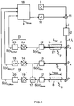
- a portion of the light of a tunable light source usually a continuously tunable laser such as a diode laser, is passed through a reference gas comprising the known gas component or another suitable gas component of constant concentration. Afterwards the light is detected by a reference detector. Another portion of the light is directed to a monitor detector for normalization purposes. Yet another portion of the light is passed through the gas sample and thereafter to a measuring detector.
- the light emitted by the light source is modulated with a frequency f m , while the wavelength is swept over a molecular absorption line of the gas component.
- wavelength dependent absorption converts some of the wavelength modulation into an intensity modulation of the light.
- the light will have an overtone spectrum generated by the absorption process, the harmonic content of the spectrum being dependent on the width and shape of the molecular absorption line in the gas and the etalons in the spectroscopy system.
- the modulation of the emitted light can most conveniently be accomplished by modulation of the injection current of the diode laser, which imposes modulation on the wavelength and to some extend on the intensity of the emitted light.
- the demodulated Nf m absorption signal depends not only on the concentration of the measured gas but also on the modulation parameters of the light source, variations of these modulation parameters can affect the accuracy of the measurement.
- the concentration of the gas component is calculated from the measuring detector output and the reference detector output which contain a factor dependent on the modulation amplitude of the diode laser and on the width of the absorption line.
- the width of the absorption line is described by a mathematical expression containing the unknown gas pressure (or gas temperature at fixed reference gas volume).
- the concentration is determined from the measuring and reference detector outputs, the mathematical expression of the width of the absorption line, the measured gas pressures and the modulation amplitude, the latter is assumed to be known.
- the invention now seeks to provide a wavelength modulation spectroscopy method, which automatically compensates for variations of the modulation parameters of the light source in real time.
- the approach in this invention is to provide a mathematical description of the demodulated reference detector output based on Fourier analysis of the modulated light and on a mathematical expression for the absorption line, said mathematical description comprising the unknown modulation parameters of the light source, and determining said modulation parameters from the demodulated reference detector output and its mathematical description.
- the concentration of the gas component in the gas sample is determined by providing a further equivalent mathematical description of the demodulated measuring detector output based on Fourier analysis of the modulated light and on a mathematical expression for the absorption line, said further mathematical description comprising said modulation parameters and the unknown concentration of the gas component of interest in the gas sample, and determining said concentration of the gas component from the demodulated measuring detector output, its mathematical description and the determined modulation parameters.
- I is the intensity of the light 1 after passing through the measurement path 5
- I L is the intensity of the light 1 emitted from the light source 2
- T Meas is a transmission factor over the measurement path 5, which transmission factor stands for the wavelength independent transmission of the optical system
- L Meas is the length of the measurement path 5
- ⁇ is the wavelength dependent absorption coefficient
- ⁇ c the line center frequency
- ⁇ ⁇ / ⁇
- the light 1 of the diode laser 2 is modulated through its injection current i, which imposes modulation on the optical frequency ⁇ L and to some extend on the intensity I L of the emitted light 1.
- the modulation is performed by a first modulation means 9 generating a sinusoidal signal at a frequency f m and a second modulation means 10 generating a periodic slow sweep function, which may be part-wise linear in time or of an arbitrary shape.
- the signals of said first and second modulation means 9 and 10 are summed in adding means 11 and fed to a modulation input of the diode laser 2.
- ⁇ 0 (t) represents a sweep of the optical frequency over the absorption line of interest
- ⁇ a is the modulation amplitude of the optical frequency ⁇ L at the modulation frequency f m .
- the modulation of the optical frequency ⁇ L follows the modulation of the injection current i without phase shift.
- the modulation of the injection current i of the diode laser 2 also results in modulation of the intensity I L of the emitted light 1:
- I L v 0 v a t I L , 0 v 0 + ⁇ 1 v a cos 2 ⁇ f m t + ⁇
- I L,0 ( ⁇ 0 ) the slow intensity variation due to the sweep of the optical frequency of the light 1
- ⁇ 1 is defined as the linear intensity modulation coefficient.
- Equation 5 possible nonlinear terms of the intensity modulation of the emitted light 1 are neglected.
- the optical frequency of the emitted light 1 sweeps over the molecular absorption line of interest of the gas sample 8 in the measurement path 5, while the light 1 is modulated with the frequency f m . Due to the nonlinear wavelength dependent absorption the light 1 will have an overtone spectrum, the harmonic content of the spectrum being dependent on the width and shape of the molecular absorption line.
- the monitor detector output S Mon is fed via an analog-to-digital converter 14 and a low-pass filter 15 to a calculating means 16 of the spectroscopy system.
- the monitor detector output S Mon is further used for correcting any transmission changes in the measurement path 5 and is therefore fed to an automatic gain control unit 17 together with the measuring detector output S Meas .
- Equation 7 As the line-shape function ⁇ ( ⁇ L ,t) follows the modulation of the frequency without phase delay, only the cosine terms in the series expansion are needed.
- Equation 6 and 11 By inserting Equations 6 and 11 into Equation 7 one obtains an optical-frequency-dependent expression for measuring detector output S( ⁇ ) Meas .
- a first demodulation means 18 comprising an analog-to-digital converter 19 and a lock-in amplifier 20 for digitizing the gained measuring detector output S( ⁇ ) Meas and converting it to base band.
- the demodulation at Nf m shifts the measurement from frequencies near DC, where the light source 2 is noisy, into a higher frequency range, where the noise is lower, thus improving the measurement sensitivity by approximately an order of 10 2 -10 3 compared to a direct unmodulated absorption measurement.
- the in-phase component of the measuring detector output S( ⁇ ) Meas demodulated at Nf m can be written as: S v N , Meas e ⁇ ⁇ G Mon A Meas T c Meas p Meas 1 ⁇ Meas L Meas I L , 0 e v 0 ⁇ N e v ⁇ 0 v ⁇ a + ⁇ 1 v a cos ⁇ 2 ⁇ N ⁇ 1 e v ⁇ 0 v ⁇ a + ⁇ N + 1 e v ⁇ 0 v ⁇ a
- m ⁇ 1 ⁇ a is the intensity modulation amplitude.
- the demodulated measuring detector output S( ⁇ ) Meas can be presented as a product of the concentration (mole fraction) C Meas of the absorbing gas component, a known pressure and temperature dependent parameter par(T,p) and a function ⁇ Meas ( ⁇ 0 , ⁇ a ,m, ⁇ Meas ) dependent on laser modulation parameters and the width of the molecular absorption line of interest.
- yet another portion of the light 1 of the diode laser 2 is passed through the reference path 7, which contains in a reference cell of known length L Ref a reference gas 21 comprising the gas component to be detected in the gas sample 8 in a known concentration.
- the reference detector 22 After passing through the reference path 7 the light 1 impinges onto a reference detector 22.
- the reference detector output S( ⁇ ) Ref is demodulated at the higher harmonic Nf m in a second demodulation means 23 comprising an analog-to-digital converter 24 and a lock-in amplifier 25.
- the demodulated reference detector output S( ⁇ ) N,Ref can be written as a product of a constant value and a function ⁇ Ref ( ⁇ 0 , ⁇ a , m) , which is solely dependent on laser modulation parameters, since the half width ⁇ Ref of the reference absorption line is also constant.
- the demodulated measuring detector output S( ⁇ ) N,Meas and reference detector output S( ⁇ ) N,Ref and the low-pass filtered monitor detector output S Mon,LP are fed to the calculating means 16 for calculating the concentration of the gas component in the gas sample 8 and for automatically correcting any changes of the FM/AM parameters of the diode laser 2 in real time.
- Figure 2 shows a functional block diagram of the calculating means 16.
- the average value I L,0 ( ⁇ ) of the intensity of the modulated light 1 is calculated from the low-pass filtered monitor detector output S Mon,LP and the known constant gain G Mon by using Equation 8.
- Equation 15 is applied to the demodulated reference detector output S( ⁇ ) N,Ref . Since I L,0 ( ⁇ ) is provided and the width ⁇ Ref of the reference absorption line is constant, the laser modulation parameters, i. e. the intensity modulation amplitude m and the frequency modulation amplitude ⁇ a can be extracted.
- the gas in the reference path 7 do not have to be the same as the gas component to be measured in the measurement path 5.
- the concentration, temperature and pressure of the gas in the reference path 7 are kept constant, thus assuring a constant width ⁇ Ref of the reference absorption line.
- the parameters ⁇ a and m are then used for determining the concentration c Meas of the gas component of interest in the measurement path 5 by fitting Equation 13 to the demodulated measuring detector output S( ⁇ ) N,Meas in block 28 and dividing the result c Meas par(T,p) by the known parameter par(T,p) in block 29.
- This method allows real time monitoring of any changes in FM/AM laser characteristics in the frequency band around f m and any drifts of the sine amplitude generated in the first modulation means 9.
- the width ⁇ Ref of the reference absorption line is extracted from the fit of Equation 15 to the demodulated reference detector output S( ⁇ ) N,Ref in block 27 and afterwards compared to an initial recorded value ⁇ Ref,initial in block 30.
- the ratio is then fed to a sweep control unit 31, which controls the amplitude of the slow sweep function generated by the second modulation means 10.
Landscapes
- Physics & Mathematics (AREA)
- Spectroscopy & Molecular Physics (AREA)
- General Physics & Mathematics (AREA)
- Optics & Photonics (AREA)
- Health & Medical Sciences (AREA)
- Life Sciences & Earth Sciences (AREA)
- Chemical & Material Sciences (AREA)
- Analytical Chemistry (AREA)
- Biochemistry (AREA)
- General Health & Medical Sciences (AREA)
- Immunology (AREA)
- Pathology (AREA)
- Investigating Or Analysing Materials By Optical Means (AREA)
Claims (5)
- Verfahren zur Wellenlängenmodulationsspektroskopie zum Messen der Konzentration (cMeas) einer interessierenden Gaskomponente in einer Gasprobe (8), das die folgenden Schritte umfasst:- Schicken eines Anteils des Lichts (1) einer Lichtquelle (2) durch ein Referenzgas (21) und danach zu einem Referenzdetektor (22), wobei das Referenzgas (21) die interessierende Gaskomponente oder eine andere geeignete Gaskomponente in einer bekannten Konzentration umfasst,- Schicken eines anderen Anteils des Lichts (1) durch die Gasprobe und danach zu einem Messdetektor (12),- Modulieren der Wellenlänge des Lichts (1) mit einer Frequenz (fm), während die Wellenlänge eine Absorptionslinie der Gaskomponente überstreicht,- Demodulieren der Referenzdetektorausgabe (S(ν)Ref) mit einer höheren Harmonischen (Nfm) der Frequenz (fm),- Demodulieren der Messdetektorausgabe (S(ν)Meas) mit der höheren Harmonischen (Nfm) der Frequenz (fm) und- Bestimmen der Konzentration (cMeas) der Gaskomponente aus den demodulierten Mess- und Referenzdetektorausgaben (S(ν)N,Ref, S(ν)N,Meas), gekennzeichnet durch- Bereitstellen einer mathematischen Beschreibung der demodulierten Referenzdetektorausgabe (S(ν)N,Ref) basierend auf der Fourier-Analyse des modulierten Lichts (1) und einem mathematischen Ausdruck für die Absorptionslinie, wobei die mathematische Beschreibung unbekannte Modulationsparameter bezüglich der Modulation des Lichts (1) umfasst,- Bestimmen der Modulationsparameter aus der demodulierten Referenzdetektorausgabe (S(ν)N,Ref) und ihrer mathematischen Beschreibung,- Bereitstellen einer weiteren mathematischen Beschreibung der demodulierten Messdetektorausgabe (S(ν)N,Meas) basierend auf der Fourier-Analyse des modulierten Lichts (1) und einem mathematischen Ausdruck für die Absorptionslinie, wobei die weitere mathematische Beschreibung die unbekannten Modulationsparameter und die unbekannte Konzentration (cMeas) der interessierenden Gaskomponente in der Gasprobe (8) umfasst, und- Bestimmen der Konzentration (cMeas) der Gaskomponente aus der demodulierten Messdetektorausgabe (S(ν)N,Meas), deren mathematischer Beschreibung und den bestimmten Modulationsparametern.
- Verfahren nach Anspruch 1, wobei die Lorentz-Linienformfunktion für den mathematischen Ausdruck für die Absorptionslinie verwendet wird.
- Verfahren nach Anspruch 1 oder 2, das ferner die folgenden Schritte umfasst:- Lenken eines anderen Anteils des Lichts (1) zu einem Überwachungsdetektor (13), undwobei die mathematische Beschreibung der demodulierten Referenzdetektorausgabe (S(ν)N,Ref) einen Mittelwert der Intensität des modulierten Lichts (1) enthält, und wobei der Mittelwert aus der Überwachungsdetektorausgabe (S(ν)Mon) durch Tiefpass-Filtern extrahiert wird.
- Verfahren nach einem der vorhergehenden Ansprüche, wobei die mathematische Beschreibung der demodulierten Referenzdetektorausgabe (S(ν)N,Ref) gegeben ist durch:
 wobei ηRef ein Instrumentfaktor und TRef ein Transmissionsfaktor über einen Referenzpfad 7 ist, der das Referenzgas (21) enthält und eine Länge LRef aufweist,ARef (T) und
 γRef der halben Halbwertsbreite (HWHM) der Absorptionslinie entspricht,cRef der Molfraktion der absorbierenden Gaskomponente entspricht,pRef dem Gesamtdruck im Referenzpfad 7 entspricht,
 m und νa eine Intensität bzw. einen Frequenzmodulationsparameter darstellen.
 - Verfahren nach einem der vorhergehenden Ansprüche, wobei die mathematische Beschreibung der demodulierten Messdetektorausgabe (S(ν)N,Meas) gegeben ist durch:
 wobei cMeas der Konzentration (Molfraktion) der zu messenden Gaskomponente entspricht,par(T,p) einem bekannten Parameter entspricht, der von dem Druck und der Temperatur der Gasprobe (8) abhängig ist,
 γMeas der halben Halbwertsbreite (HWHM) der Absorptionslinie entspricht,
 m und νa eine Intensität bzw. einen Frequenzmodulationsparameter darstellen.
Priority Applications (2)
| Application Number | Priority Date | Filing Date | Title |
|---|---|---|---|
| EP03029102.5A EP1544604B1 (de) | 2003-12-17 | 2003-12-17 | Verfahren zur Wellenlängenmodulationsspektroskopie |
| US11/011,691 US7251034B2 (en) | 2003-12-17 | 2004-12-14 | Wavelength modulation spectroscopy method |
Applications Claiming Priority (1)
| Application Number | Priority Date | Filing Date | Title |
|---|---|---|---|
| EP03029102.5A EP1544604B1 (de) | 2003-12-17 | 2003-12-17 | Verfahren zur Wellenlängenmodulationsspektroskopie |
Publications (2)
| Publication Number | Publication Date |
|---|---|
| EP1544604A1 EP1544604A1 (de) | 2005-06-22 |
| EP1544604B1 true EP1544604B1 (de) | 2017-09-27 |
Family
ID=34486237
Family Applications (1)
| Application Number | Title | Priority Date | Filing Date |
|---|---|---|---|
| EP03029102.5A Expired - Lifetime EP1544604B1 (de) | 2003-12-17 | 2003-12-17 | Verfahren zur Wellenlängenmodulationsspektroskopie |
Country Status (2)
| Country | Link |
|---|---|
| US (1) | US7251034B2 (de) |
| EP (1) | EP1544604B1 (de) |
Families Citing this family (23)
| Publication number | Priority date | Publication date | Assignee | Title |
|---|---|---|---|---|
| US8994947B2 (en) * | 2001-03-19 | 2015-03-31 | Pranalytica, Inc. | Diagnostic method for high sensitivity detection of component concentrations in human gas emissions |
| EP1544604B1 (de) * | 2003-12-17 | 2017-09-27 | Siemens Aktiengesellschaft | Verfahren zur Wellenlängenmodulationsspektroskopie |
| EP1693665B1 (de) * | 2005-02-22 | 2008-12-03 | Siemens Aktiengesellschaft | Verfahren und Vorrichtung zum Nachweis von Spurengasen |
| RU2299423C1 (ru) * | 2005-10-11 | 2007-05-20 | Общество с ограниченной ответственностью "Интеллект-Клуб РадиоФосфор-32" | Оптико-электронный спектральный газоанализатор |
| DE102006016855A1 (de) * | 2006-04-07 | 2007-10-11 | Emerson Process Management Gmbh & Co. Ohg | Verfahren und Vorrichtung zur Messung der optischen Absorption von Proben |
| US20100242572A1 (en) * | 2006-10-28 | 2010-09-30 | James Yu | Wavelength modulation spectroscopy for simultaneous measurement of two or more gas ingredients |
| EP1969997A1 (de) * | 2007-03-12 | 2008-09-17 | Radiometer Basel AG | Sensorensystem |
| US7969576B1 (en) * | 2007-03-23 | 2011-06-28 | The Regents Of The University Of California | Optical sensing based on wavelength modulation spectroscopy |
| DE102007015611A1 (de) * | 2007-03-30 | 2008-10-09 | Siemens Ag | Verfahren zur nichtdispersiven Infrarot-Gasanalyse |
| EP2072979B1 (de) * | 2007-12-21 | 2012-02-29 | Siemens Aktiengesellschaft | Verfahren zur Messung der Konzentration einer Gaskomponente in einem Messgas |
| US7957001B2 (en) * | 2008-10-10 | 2011-06-07 | Ge Infrastructure Sensing, Inc. | Wavelength-modulation spectroscopy method and apparatus |
| US7943915B2 (en) | 2008-10-10 | 2011-05-17 | Ge Infrastructure Sensing, Inc. | Method of calibrating a wavelength-modulation spectroscopy apparatus |
| DE102012202893B3 (de) * | 2012-02-27 | 2013-01-17 | Siemens Aktiengesellschaft | Verfahren zur Messung der Konzentration einer Gaskomponente in einem Messgas und Laserspektrometer |
| US8896836B1 (en) * | 2012-04-23 | 2014-11-25 | Southwest Sciences Incorporated | Fluid properties measurements using wavelength modulation spectroscopy with first harmonic detection |
| EP2946194B1 (de) | 2013-01-17 | 2023-07-05 | Detector Electronics Corporation | Gasdetektor mit offener messstrecke |
| CN103411678B (zh) * | 2013-07-24 | 2015-11-18 | 江苏苏威尔科技有限公司 | 一种光路自动校正的色度计及色度测量方法 |
| EP2857812B1 (de) * | 2013-10-02 | 2016-04-27 | Siemens Aktiengesellschaft | Verfahren zur messung der konzentration einer gaskomponente in einem messgas |
| GB2524725B (en) * | 2014-03-24 | 2016-03-30 | Servomex Group Ltd | Method and system for correcting incident light fluctuations in absorption spectroscopy |
| CN103868884B (zh) * | 2014-03-27 | 2016-06-15 | 清华大学 | 一种基于调制系数的气体吸收率在线测量方法 |
| EP3001180A1 (de) * | 2014-09-29 | 2016-03-30 | Siemens Aktiengesellschaft | Verfahren und Gasanalysator zur Messung der Konzentration einer Gaskomponente in einem Messgas |
| EP3364169B1 (de) | 2017-02-17 | 2019-05-15 | Siemens Aktiengesellschaft | Prozess-gasanalysator |
| AT521624B1 (de) * | 2019-01-17 | 2020-03-15 | Scan Messtechnik Gmbh | Vorrichtung und Verfahren zum Erfassen von Eigenschaften eines zu untersuchenden Fluids |
| US11041803B2 (en) * | 2019-03-26 | 2021-06-22 | International Business Machines Corporation | Feed-forward spectral calibration methodology for line-scanned tunable laser absorption spectroscopy |
Family Cites Families (6)
| Publication number | Priority date | Publication date | Assignee | Title |
|---|---|---|---|---|
| US6351309B1 (en) * | 1991-08-06 | 2002-02-26 | Southwest Sciences Incorporated | Dual modulation laser line-locking technique for wavelength modulation spectroscopy |
| US5572031A (en) * | 1994-11-23 | 1996-11-05 | Sri International | Pressure- and temperature-compensating oxygen sensor |
| US6356350B1 (en) * | 1998-07-30 | 2002-03-12 | Southwest Sciences Incorporated | Wavelength modulation spectroscopy with multiple harmonic detection |
| US6611335B1 (en) * | 1999-08-17 | 2003-08-26 | Southwest Sciences Incorporated | Tone burst diode laser spectroscopy |
| DE60310712T2 (de) * | 2003-08-28 | 2007-10-11 | Siemens Ag | Verfahren und System zur Wellenlängenmodulationsspektrometrie |
| EP1544604B1 (de) * | 2003-12-17 | 2017-09-27 | Siemens Aktiengesellschaft | Verfahren zur Wellenlängenmodulationsspektroskopie |
-
2003
- 2003-12-17 EP EP03029102.5A patent/EP1544604B1/de not_active Expired - Lifetime
-
2004
- 2004-12-14 US US11/011,691 patent/US7251034B2/en not_active Expired - Lifetime
Non-Patent Citations (1)
| Title |
|---|
| None * |
Also Published As
| Publication number | Publication date |
|---|---|
| US7251034B2 (en) | 2007-07-31 |
| EP1544604A1 (de) | 2005-06-22 |
| US20050140979A1 (en) | 2005-06-30 |
Similar Documents
| Publication | Publication Date | Title |
|---|---|---|
| EP1544604B1 (de) | Verfahren zur Wellenlängenmodulationsspektroskopie | |
| EP2072979B1 (de) | Verfahren zur Messung der Konzentration einer Gaskomponente in einem Messgas | |
| EP1510798B1 (de) | Verfahren und System zur Wellenlängenmodulationsspektrometrie | |
| JP6022456B2 (ja) | 時間領域信号の減衰定数を決定する方法とシステム | |
| US4410273A (en) | Scanning laser spectrometer | |
| US6356350B1 (en) | Wavelength modulation spectroscopy with multiple harmonic detection | |
| EP2122328B1 (de) | Druckunabhängiger spurengasnachweis | |
| EP2942616B1 (de) | Gasabsorptionsspektroskopiesystem und gasabsorptionsspektroskopieverfahren | |
| US6940599B1 (en) | Envelope functions for modulation spectroscopy | |
| EP2000792A1 (de) | Verfahren zur Messung der Konzentration einer Gaskomponente in einem Messgas | |
| US6044329A (en) | Laser gas analyzer and a method of operating the laser to reduce non-linearity errors | |
| JP7135608B2 (ja) | ガス吸収分光装置、及びガス吸収分光方法 | |
| US4084906A (en) | Multigas digital correlation spectrometer | |
| KR100747768B1 (ko) | 파장 변조 방법을 이용한 유해 가스 측정 장치 | |
| EP3940368B1 (de) | Vorrichtung und verfahren zur messung von zirkulardichroismus | |
| US5742399A (en) | Method for stabilizing the wavelength in a laser spectrometer system | |
| Strahl et al. | Comparison of laser-based photoacoustic and optical detection of methane | |
| Chaux et al. | Relative line intensity measurement in absorption spectra using a tunable diode laser at 1.6 μm: application to the determination of 13CO2/12CO2 isotope ratio | |
| Werle | Analytical applications of infrared semiconductor lasers in atmospheric trace gas monitoring | |
| RU2011971C1 (ru) | Способ анализа газов с помощью свч-энергии | |
| CN118896932A (zh) | 一种用于遥测场景下的tdlas系统气体浓度测量方法 | |
| CN121141584A (zh) | 一种基于量子级联激光的气体检测方法 | |
| IT202100032276A1 (it) | Un apparato e un metodo fotoacustico per rilevare un analita in un campione di un materiale da ispezionare | |
| Bullock et al. | Sensitive nonintrusive sensing by modulation spectroscopy with diode lasers | |
| Werle | Fast sub-ppb Trace Gas Detection by Infrared Diode-Laser FM-Spectroscopy |
Legal Events
| Date | Code | Title | Description |
|---|---|---|---|
| PUAI | Public reference made under article 153(3) epc to a published international application that has entered the european phase |
Free format text: ORIGINAL CODE: 0009012 |
|
| 17P | Request for examination filed |
Effective date: 20040906 |
|
| AK | Designated contracting states |
Kind code of ref document: A1 Designated state(s): AT BE BG CH CY CZ DE DK EE ES FI FR GB GR HU IE IT LI LU MC NL PT RO SE SI SK TR |
|
| AX | Request for extension of the european patent |
Extension state: AL LT LV MK |
|
| AKX | Designation fees paid |
Designated state(s): DE FR GB SE |
|
| 17Q | First examination report despatched |
Effective date: 20060905 |
|
| RAP1 | Party data changed (applicant data changed or rights of an application transferred) |
Owner name: SIEMENS AKTIENGESELLSCHAFT |
|
| RAP1 | Party data changed (applicant data changed or rights of an application transferred) |
Owner name: SIEMENS AKTIENGESELLSCHAFT |
|
| GRAP | Despatch of communication of intention to grant a patent |
Free format text: ORIGINAL CODE: EPIDOSNIGR1 |
|
| INTG | Intention to grant announced |
Effective date: 20170328 |
|
| GRAS | Grant fee paid |
Free format text: ORIGINAL CODE: EPIDOSNIGR3 |
|
| GRAA | (expected) grant |
Free format text: ORIGINAL CODE: 0009210 |
|
| RAP1 | Party data changed (applicant data changed or rights of an application transferred) |
Owner name: SIEMENS AKTIENGESELLSCHAFT |
|
| AK | Designated contracting states |
Kind code of ref document: B1 Designated state(s): DE FR GB SE |
|
| REG | Reference to a national code |
Ref country code: GB Ref legal event code: FG4D |
|
| REG | Reference to a national code |
Ref country code: DE Ref legal event code: R096 Ref document number: 60350636 Country of ref document: DE |
|
| REG | Reference to a national code |
Ref country code: FR Ref legal event code: PLFP Year of fee payment: 15 |
|
| PG25 | Lapsed in a contracting state [announced via postgrant information from national office to epo] |
Ref country code: SE Free format text: LAPSE BECAUSE OF FAILURE TO SUBMIT A TRANSLATION OF THE DESCRIPTION OR TO PAY THE FEE WITHIN THE PRESCRIBED TIME-LIMIT Effective date: 20170927 |
|
| REG | Reference to a national code |
Ref country code: DE Ref legal event code: R097 Ref document number: 60350636 Country of ref document: DE |
|
| PLBE | No opposition filed within time limit |
Free format text: ORIGINAL CODE: 0009261 |
|
| STAA | Information on the status of an ep patent application or granted ep patent |
Free format text: STATUS: NO OPPOSITION FILED WITHIN TIME LIMIT |
|
| 26N | No opposition filed |
Effective date: 20180628 |
|
| PGFP | Annual fee paid to national office [announced via postgrant information from national office to epo] |
Ref country code: FR Payment date: 20221214 Year of fee payment: 20 |
|
| PGFP | Annual fee paid to national office [announced via postgrant information from national office to epo] |
Ref country code: GB Payment date: 20230103 Year of fee payment: 20 Ref country code: DE Payment date: 20230217 Year of fee payment: 20 |
|
| REG | Reference to a national code |
Ref country code: DE Ref legal event code: R071 Ref document number: 60350636 Country of ref document: DE |
|
| REG | Reference to a national code |
Ref country code: GB Ref legal event code: PE20 Expiry date: 20231216 |
|
| PG25 | Lapsed in a contracting state [announced via postgrant information from national office to epo] |
Ref country code: GB Free format text: LAPSE BECAUSE OF EXPIRATION OF PROTECTION Effective date: 20231216 |
|
| PG25 | Lapsed in a contracting state [announced via postgrant information from national office to epo] |
Ref country code: GB Free format text: LAPSE BECAUSE OF EXPIRATION OF PROTECTION Effective date: 20231216 |