EP1544586A1 - Sensor element - Google Patents
Sensor element Download PDFInfo
- Publication number
- EP1544586A1 EP1544586A1 EP04026987A EP04026987A EP1544586A1 EP 1544586 A1 EP1544586 A1 EP 1544586A1 EP 04026987 A EP04026987 A EP 04026987A EP 04026987 A EP04026987 A EP 04026987A EP 1544586 A1 EP1544586 A1 EP 1544586A1
- Authority
- EP
- European Patent Office
- Prior art keywords
- sensor
- sensor element
- cover
- lever
- magnet
- Prior art date
- Legal status (The legal status is an assumption and is not a legal conclusion. Google has not performed a legal analysis and makes no representation as to the accuracy of the status listed.)
- Withdrawn
Links
- 230000005291 magnetic effect Effects 0.000 claims abstract description 18
- 238000011156 evaluation Methods 0.000 claims abstract description 6
- 239000002828 fuel tank Substances 0.000 claims description 28
- 239000004020 conductor Substances 0.000 claims description 21
- 239000002775 capsule Substances 0.000 claims description 6
- 238000003780 insertion Methods 0.000 claims description 6
- 230000037431 insertion Effects 0.000 claims description 6
- 239000000463 material Substances 0.000 claims description 5
- 239000000615 nonconductor Substances 0.000 claims description 2
- 230000005355 Hall effect Effects 0.000 abstract description 2
- 238000013459 approach Methods 0.000 description 14
- 239000000446 fuel Substances 0.000 description 11
- 239000011347 resin Substances 0.000 description 6
- 229920005989 resin Polymers 0.000 description 6
- 238000005476 soldering Methods 0.000 description 5
- 239000000919 ceramic Substances 0.000 description 4
- 238000005266 casting Methods 0.000 description 3
- 238000009792 diffusion process Methods 0.000 description 3
- 238000004519 manufacturing process Methods 0.000 description 3
- 238000005259 measurement Methods 0.000 description 3
- 229910000679 solder Inorganic materials 0.000 description 3
- 230000007797 corrosion Effects 0.000 description 2
- 238000005260 corrosion Methods 0.000 description 2
- 238000013461 design Methods 0.000 description 2
- 239000000565 sealant Substances 0.000 description 2
- 125000006850 spacer group Chemical group 0.000 description 2
- 230000001629 suppression Effects 0.000 description 2
- 229910018072 Al 2 O 3 Inorganic materials 0.000 description 1
- 239000002313 adhesive film Substances 0.000 description 1
- 230000000694 effects Effects 0.000 description 1
- 230000005294 ferromagnetic effect Effects 0.000 description 1
- 230000009969 flowable effect Effects 0.000 description 1
- 239000012530 fluid Substances 0.000 description 1
- 230000000149 penetrating effect Effects 0.000 description 1
- 230000002093 peripheral effect Effects 0.000 description 1
- 230000000704 physical effect Effects 0.000 description 1
- 238000012545 processing Methods 0.000 description 1
- 230000006641 stabilisation Effects 0.000 description 1
- 238000011105 stabilization Methods 0.000 description 1
- 230000008719 thickening Effects 0.000 description 1
Images


Classifications
-
- G—PHYSICS
- G01—MEASURING; TESTING
- G01R—MEASURING ELECTRIC VARIABLES; MEASURING MAGNETIC VARIABLES
- G01R33/00—Arrangements or instruments for measuring magnetic variables
- G01R33/02—Measuring direction or magnitude of magnetic fields or magnetic flux
- G01R33/06—Measuring direction or magnitude of magnetic fields or magnetic flux using galvano-magnetic devices
- G01R33/07—Hall effect devices
-
- G—PHYSICS
- G01—MEASURING; TESTING
- G01F—MEASURING VOLUME, VOLUME FLOW, MASS FLOW OR LIQUID LEVEL; METERING BY VOLUME
- G01F23/00—Indicating or measuring liquid level or level of fluent solid material, e.g. indicating in terms of volume or indicating by means of an alarm
- G01F23/30—Indicating or measuring liquid level or level of fluent solid material, e.g. indicating in terms of volume or indicating by means of an alarm by floats
- G01F23/32—Indicating or measuring liquid level or level of fluent solid material, e.g. indicating in terms of volume or indicating by means of an alarm by floats using rotatable arms or other pivotable transmission elements
- G01F23/38—Indicating or measuring liquid level or level of fluent solid material, e.g. indicating in terms of volume or indicating by means of an alarm by floats using rotatable arms or other pivotable transmission elements using magnetically actuated indicating means
Definitions
- the invention relates to a sensor element for non-contact measurement of a Magnetic field in an aggressive environment, especially for use within a fuel tank of a motor vehicle.
- a non-contact level sensor is known to the Measurement of a level in a fuel tank as a sensor element a Hall sensor used, which detects the magnetic field of a magnet.
- a Hall sensor used, which detects the magnetic field of a magnet.
- the lever is rotatably supported via a rotation axis.
- the The axis of rotation is partially formed by the magnet designed as a ring magnet includes.
- the ring magnet is in this case between the Hall sensor and the Rotary axis arranged.
- the magnet is in a two-piece case arranged, wherein the housing halves by means of a casting resin are sealed liquid-tight.
- the Hall sensor is molded in a housing formed in a housing Bag arranged, which is also filled with cast resin.
- the protection of the casting resin is not sufficient because of fuel on the Housing wall comes into contact with the casting resin by, through this gradually diffused through, so that the sensor element, for example, by Corrosion is damaged, so that the life is relatively short.
- the object of the invention is to provide a sensor element with an aggressive Environment to provide increased lifespan.
- the sensor element according to the invention with which a magnetic field generated by a movable magnet is measured, has a base element, which consists of an electrical insulator material, in particular a ceramic, such as Al 2 O 3 .
- a detector element With the base element, a detector element is connected, which has a physical effect, for. B. Hall Stamm, the direction and / or strength of the magnetic field detected.
- a metallic cover element is connected to the base element. The cover element is spaced from the detector element, ie the detector element is covered by a direct electrical contact through the cover and protected from the environment. Electrical conductors which are guided through the cover element and / or through the base element for connection to a voltage source or an evaluation unit are connected to the detector element.
- the Metallic cover and possibly the base element are at least for Fuel diffusion resistant, i. a diffusive mass transport through the Cover element or possibly through the base member is in contrast to Cast resin or plastic undetectable.
- the connection between the cover member and the base member at these locations preferably cohesively, for example by soldering, so that the connection points are resistant to diffusion at least for fuel.
- the metallic cover element with the base element is in the Base element, for example, a solderable metallized ceramic, so that at least the metallic components of the ceramic for the cohesive Connection can be melted.
- the detector element is through the inventive design of the sensor element from an aggressive Environment, such as fuel vapor in particular in a fuel tank are sufficiently protected, so that the life increases significantly is.
- the cover member and the base member may be a particularly have simple geometry, so that the production of the inventive Sensor element accordingly simplified and thus cheaper.
- the detector element has in particular a Hall sensor in order to the Magnetic field of the magnet with the help of the Hall effect to detect by a Hall voltage is measured.
- the detector element additionally or alternatively an AMR sensor (anisotropic magnetoresistive Sensor) and / or a GMR sensor (giant magneto resistance sensor).
- AMR sensor anisotropic magnetoresistive Sensor
- GMR sensor giant magneto resistance sensor
- the magneto-resistance effect of the AMR / GMR sensor can with Help of a bridge circuit measured and comparable to a Hall sensor in a voltage change are transferred. Furthermore, the AMR / GMR sensor be made significantly smaller compared to a Hall sensor.
- the sensor element preferably has a covering capsule.
- the cover capsule has the cover and a lid associated with this.
- the lid is preferably made of the same material as the cover and is connected to this in particular cohesively, for example by soldering.
- the base member is completely within the cover member arranged. This makes it possible, the base member relative to Position cover without, for example, when the lid with the cover is connected, an unwanted change in position of the Base element occurs.
- the Connection between cover and cover element if possible, in one place which is particularly far away from the aggressive environment. As a result, the protection of the detector element is further improved and the Lifespan increased.
- the cover and / or the Base element on a directed away from the detector element approach serves to limit a depth of insertion of the cover in one Opening.
- the approach is designed for this example as a protruding nose, such that the approach when passing the sensor element through an opening abuts on the component which has the opening, whereby the maximum Insertion depth is defined.
- Sensor element according to the invention by particularly simple structural means as an independent module for a non-contact level sensor too use.
- the approach can, for example, by a material thickening or Material expansion be designed as a paragraph. This forms a step off, which can act as a stop to limit the insertion depth.
- the approach to an outside of the cover or of the base member at a right angle which is concave.
- the Stop surface and the outside are thus formed perpendicular to each other, resulting in a sharp groove.
- a sealant such as an O-ring, in a defined Able to be arranged.
- the approach is configured circumferentially, so that the approach is not only as a stop, but also acts as a splash guard, the aggressive Media, such as fuel, from that of the aggressive medium derived away from the remote part of the sensor element. If the cover from the aggressive medium seen from behind the approach with a lid or the like. is added, an additional protection of the encapsulated detector element reached.
- the aggressive Media such as fuel
- the electrical conductors of the sensor element according to the invention can be used as cables be carried out, for example, led through an opening to the outside are, with the opening in particular with the help of a corrosion resistant and sealed diffusion-resistant sealant.
- at least one of the electrical conductors configured as a conductor channel in the Base element is arranged.
- the base element is thus comparable to one Printed circuit board configured, this "board" is multi-layered off, to coat the conductors, preferably over the entire peripheral surface.
- the detector element can by individual solder points with the respective conductor get connected.
- the cover or a with the Cover connected lid a contact element for the passage of have electric current.
- the contact element is preferably opposite the cover or the cover electrically isolated and has in particular the lowest possible electrical resistance.
- the invention further relates to a non-contact level sensor, in particular for a fuel tank in a motor vehicle.
- the level sensor has a rotatably mounted lever on which with a float and a magnet connected is. Depending on the position of the float becomes the lever rotated, which changes the positions of the magnet. Between the Magnet and a rotation axis, a sensor element is arranged, the in particular as further described above. The order the sensor element is made such that the from the sensor element measured magnetic field as a function of the position of the float changes.
- the movable magnet is further from the axis of rotation spaced, so that the magnet in a position change of the float covers a greater distance. Due to the longer movement path of the Magnet takes place at a comparable change in position of the float a greater change in the magnetic element measured by the sensor element Field.
- the sensor element can thus be correspondingly smaller and more compact be executed and can simultaneously fill the level with a higher Measure accuracy. Furthermore, it is sufficient to use only the detector element of the Sensor element to protect against fuels and fuel vapors or the like., because the other components are not sensitive electrical components exhibit.
- the non-contact level sensor can therefore accordingly easy to be designed.
- the magnet is preferably at least as a segment of a ring magnet executed. This results in a relatively uniform, undisturbed Magnetic field measured by the sensor element.
- the sensor element can be provided with suppression modules, whereby the measurement accuracy is improved.
- the level sensor has an intermediate piece, with which the lever is rotatably connected. Furthermore, the intermediate piece has a Opening for receiving the sensor element.
- the sensor element is in such arranged the opening that the detector element of the sensor element of the associated with the lever side facing the intermediate piece.
- the Sensor element can therefore, for example, outside of a fuel tank on the Opening of the intermediate piece, in particular partially, in the fuel tank be brought into it.
- the sensor element has an approach, as a stop on the lever facing away from the side of the intermediate piece is applied.
- the detector element completely encapsulated on the lever-facing side of the intermediate piece to arrange, at the same time the connection with the lid and the Ladder ends of the ladder on the side of the intermediate piece facing away from the lever are arranged.
- the detector element of the Sensor element additionally protected by the intermediate piece, for example, by the spacer acts as a splash guard.
- the invention further relates to a level sensor arrangement with a Fuel tank and associated with this level sensor, the in particular, as described above, further developed.
- the Fuel tank has a receiving opening for receiving a sensor element or an intermediate piece.
- the sensor element is in the Receiving opening out that the detector element within the Fuel tanks and the conductor ends of the electrical conductors outside of the Fuel tanks are arranged. If available, especially the Connection between a cover and a lid of the Sensor element also disposed outside of the fuel tank.
- the contactless level sensor 10 has a lever 12 on, with a float 14 and a magnet 16, in particular as Segment of a ring magnet is executed, is connected.
- the magnet 16 is indirectly connected via a first housing part 18 with the lever 12.
- the Intermediate piece 22 has a tubular extension 24, over which the lever 12 is stored.
- the lever 12 and the first housing part 18 a Bolt on, for example, by clipping with the extension 24 rotatable connected is.
- the intermediate piece 22 has a second housing part 26, which is the first Housing part 18 is supported. At the same time hold the first housing part 18 and the second housing part 26 fuel that could splash against the level sensor from penetrating into the interior of the housing parts 18, 26.
- the intermediate piece 22 also has an opening 28 for receiving a Sensor element 30 on.
- the sensor element 30 is through the opening 28 in such a way arranged that it is between the magnet 16 and the rotation axis 20th is located and the magnetic field generated by the magnet 16 as far as possible hysteresis-free measures.
- the intermediate piece 22 also has a connecting element 32 to connect the level sensor 10 with a fuel tank 34. In this case, the intermediate piece 22 forms in particular a part of the fuel tank 34. If necessary has the intermediate piece a passage opening 36 to electrical Connections 38 of the sensor element 30 to a voltage source or a Pass through the evaluation unit. In the evaluation unit can from the Sensor element 30 recorded characteristic to be processed by the Characteristic, for example, programmed and / or calibrated.
- the sensor element 30 In the first embodiment of the sensor element 30 (FIG. 3) is provided with a Base member 40 a metallic cover member 42 soldered. Within a formed by the base member 40 and the cover member 42, encapsulated space 44, a detector element 46 is arranged. In which Detector element 46 may be a Hall element and / or an AMR sensor and / or a GMR sensor. The detector element 46 is on applied to the ceramic base member 40.
- the base member 40 has Conductor channels 48, which via solder joints 50 with the detector element 46th are connected.
- the sensor element 30 is guided in an opening, which is the Opening 28 of the intermediate piece 22 or around a receiving opening 52 of the Fuel tanks 34 can act.
- the sensor element 30 is so in the opening 28 and the receiving opening 52, that the detector element 46th is disposed within the fuel tank 34.
- conductor ends 54 of the Conductor channels 48 disposed outside of the fuel tank 34, whereby the Conductor ends 54 outside of the fuel tank 34 in a non-aggressive Environment via solder points or the like. With electrical cables or connections 38 can be soldered.
- the cover 42 is shown in Fig. 3 from the right in the Opening 28, 52 introduced. For location positioning, the cover 42 a shoulder 56 which serves as a stop the insertion depth of the sensor element 30th limited.
- the detector element 46 relative to the magnet 16 centered to each other to arrange.
- the detector element 46 and the magnet 16 are aligned substantially aligned with each other, so that the Detector element 46 in a substantially homogeneous, trouble-free Magnetic field is arranged.
- FIG Cover 42 contact elements 58, which via electrical conductors 60 with are connected to the detector element 46.
- the contact elements 58 are each with an electrical connection 38, for example by soldering, connected.
- the Contact elements 58 are by means of an insulating means 62 from the rest Cover element 42 performed isolated, so that short circuits are avoided.
- the cover element 42 has a projection 64, which leads to a surface 66 of the cover 42 is executed at right angles. It turns out thus between the approach 64 and the surface 66 a right angle 68.
- the sensor element 30 is inserted from the left into the opening 28, 52 in FIG. 4, so that the approach 64 limits the insertion depth as a stop. Due to the right angle 68 is in the installed state, both the approach 64 and the surface 66 in contact with the intermediate piece 22 and the fuel tank 34th
- the cover 42 In the third embodiment of the sensor element 30 (FIG Sensor element 30, a Abdeckkapsel, consisting of the cover 42 and a lid 70 is made.
- the base member 40 is completely within the Cover capsule arranged.
- the cover 42 has a nose 72, which a bottom 74 of the cover 42 has a distance, which with the Thickness of the base member 40 corresponds.
- the cover 70 has a recess 76 which also corresponds to the thickness of the base member 40.
- the Base member 40 is thus both of the cover 42 and of the Lid 70 held.
- the lid 70 and the cover 42 are preferably cohesively, in particular by soldering, connected together.
- the Lid 70 further includes a connection opening 78 through which the conductors 60 can be passed.
- the Base member 40 having conductor channels 48, by a correspondingly large executed connecting opening 78 of the lid 70, so that the Conductor ends 54 are disposed outside of the fuel tank 34.
- the sensor element 30 can be compared to the previous embodiments also be installed rotated by 90 ° (Fig. 7).
- This arrangement of Sensor element 30 is particularly suitable when as detector element 46th an AMR / GMR sensor is used.
- the detector element 46 and the Magnet 16 are preferably arranged centrally to the axis of rotation 20, so that upon rotation of the magnet 16 in the direction of an arrow 80, the direction of the magnetic field generated by the magnet 16 changes. The change of Magnetic field direction is detected by the detector element 46.
- the level sensor 10 for example, instead of the first cover-shaped housing part 18 have a rotary shaft 82, with which the Magnet 16 is connected. In particular, it may be in the magnet 16 in This embodiment is a bar magnet, so that a annular design is not required.
- the sensor element 30 at its back, d. H. on the side facing away from the magnet 16, with a film, in particular adhesive film to be connected. This can do that Sensor element 30 particularly easy with the spacer 22 and the Fuel tank 34 are connected.
Abstract
Description
Die Erfindung betrifft ein Sensorelement zur berührungslosen Messung eines Magnetfeldes in aggressiver Umgebung, insbesondere zur Verwendung innerhalb eines Kraftstofftanks eines Kraftfahrzeugs.The invention relates to a sensor element for non-contact measurement of a Magnetic field in an aggressive environment, especially for use within a fuel tank of a motor vehicle.
Aus DE 101 42 618 A1 ist ein berührungsloser Füllstandgeber bekannt, der zur Messung eines Füllstands in einem Kraftstofftank als Sensorelement einen Hallsensor verwendet, der das Magnetfeld eines Magneten detektiert. Der Magnet ist über einen Hebel mit einem Schwimmer verbunden, so dass sich das gemessene Magnetfeld des Magneten in Abhängigkeit vom Füllstand in dem Kraftstofftank ändert. Der Hebel ist über eine Drehachse drehbar gelagert. Die Drehachse wird von dem als Ringmagneten ausgebildeten Magneten teilweise umfasst. Der Ringmagnet ist hierbei zwischen dem Hallsensor und der Drehachse angeordnet. Der Magnet ist in einem zweistückigen Gehäuse angeordnet, wobei die Gehäusehälften mit Hilfe eines Gießharzes flüssigkeitsdicht verschlossen sind. Zum Schutz vor der aggressiven Umgebung in dem Kraftstofftank ist der Hallsensor in einer in einem Gehäuse eingeformten Tasche angeordnet, die ebenfalls mit Gießharz verfüllt ist.From DE 101 42 618 A1 discloses a non-contact level sensor is known to the Measurement of a level in a fuel tank as a sensor element a Hall sensor used, which detects the magnetic field of a magnet. Of the Magnet is connected via a lever to a float, so that the measured magnetic field of the magnet as a function of the level in the Fuel tank changes. The lever is rotatably supported via a rotation axis. The The axis of rotation is partially formed by the magnet designed as a ring magnet includes. The ring magnet is in this case between the Hall sensor and the Rotary axis arranged. The magnet is in a two-piece case arranged, wherein the housing halves by means of a casting resin are sealed liquid-tight. To protect against the aggressive environment in the fuel tank, the Hall sensor is molded in a housing formed in a housing Bag arranged, which is also filled with cast resin.
Nachteilig bei einem derartigen Sensorelement ist, dass erheblicher konstruktiver Aufwand betrieben werden muss, um das Sensorelement zu schützen. Es ist erforderlich, Bauteile mit komplizierten Geometrien zu verwenden, die entsprechend aufwändig und teuer in der Herstellung sind. The disadvantage of such a sensor element is that considerable constructive effort must be operated to the sensor element protect. It is necessary to have components with complicated geometries too use, which are correspondingly complex and expensive to manufacture.
Ferner reicht der Schutz des Gießharzes nicht aus, da Kraftstoff, der an der Gehäusewand vorbei in Kontakt mit dem Gießharz kommt, durch dieses allmählich hindurch diffundiert, so dass das Sensorelement beispielsweise durch Korrosion beschädigt wird, so dass die Lebensdauer verhältnismäßig kurz ist.Furthermore, the protection of the casting resin is not sufficient because of fuel on the Housing wall comes into contact with the casting resin by, through this gradually diffused through, so that the sensor element, for example, by Corrosion is damaged, so that the life is relatively short.
Aufgabe der Erfindung ist es, ein Sensorelement mit einer in einer aggressiven Umgebung erhöhten Lebensdauer zu schaffen.The object of the invention is to provide a sensor element with an aggressive Environment to provide increased lifespan.
Die Aufgabe wird erfindungsgemäß gelöst durch ein Sensorelement mit den Merkmalen des Anspruchs 1.The object is achieved by a sensor element with the Features of claim 1.
Das erfindungsgemäße Sensorelement, mit dem ein durch einen bewegbaren Magneten erzeugtes Magnetfeld gemessen wird, weist ein Basiselement auf, das aus einem elektrischen Isolatormaterial, insbesondere eine Keramik, wie beispielsweise Al2O3, besteht. Mit dem Basiselement ist ein Detektorelement verbunden, das über einen physikalischen Effekt, z. B. Hallefekt, die Richtung und/ oder Stärke des Magnetfeldes detektiert. Ferner ist mit dem Basiselement ein metallisches Abdeckelement verbunden. Das Abdeckelement ist von dem Detektorelement beabstandet, d.h. das Detektorelement ist ohne einen direkten elektrischen Kontakt durch das Abdeckelement abgedeckt und von der Umgebung geschützt. Mit dem Detektorelement sind elektrische Leiter verbunden, die durch das Abdeckelement und/ oder durch das Basiselement zur Verbindung mit einer Spannungsquelle bzw. einer Auswerteeinheit geführt sind.The sensor element according to the invention, with which a magnetic field generated by a movable magnet is measured, has a base element, which consists of an electrical insulator material, in particular a ceramic, such as Al 2 O 3 . With the base element, a detector element is connected, which has a physical effect, for. B. Hallfekt, the direction and / or strength of the magnetic field detected. Furthermore, a metallic cover element is connected to the base element. The cover element is spaced from the detector element, ie the detector element is covered by a direct electrical contact through the cover and protected from the environment. Electrical conductors which are guided through the cover element and / or through the base element for connection to a voltage source or an evaluation unit are connected to the detector element.
Durch das Abdeckelement und ggf. zusätzlich durch das Basiselement ist das Detektorelement von der Umgebung weitestgehend abgeschlossen. Das metallische Abdeckelement und ggf. das Basiselement sind zumindest für Kraftstoff diffusionsbeständig, d.h. ein diffusiver Stofftransport durch das Abdeckelement bzw. ggf. durch das Basiselement hindurch ist im Gegensatz zu Gießharz oder Kunststoff nicht nachweisbar. Sofern zwischen dem Abdeckelement und dem Basiselement Verbindungsstellen auftreten, die von der aggressiven Umgebung her zugänglich sind, erfolgt die Verbindung zwischen dem Abdeckelement und dem Basiselement an diesen Stellen vorzugsweise stoffschlüssig, beispielsweise durch Löten, so dass auch die Verbindungsstellen zumindest für Kraftstoff diffusionsbeständig sind. Zur verbesserten Lötfähigkeit des metallischen Abdeckelements mit dem Basiselement handelt es sich bei dem Basiselement beispielsweise um eine lötfähige metallisierte Keramik, so dass zumindest die metallischen Bestandteile der Keramik für die stoffschlüssige Verbindung aufgeschmolzen werden können. Das Detektorelement ist durch den erfindungsgemäßen Aufbau des Sensorelements vor einer aggressiven Umgebung, wie sie insbesondere durch Kraftstoffdämpfe in einem Kraftstofftank gegeben sind, ausreichend geschützt, so dass die Lebensdauer deutlich erhöht ist. Ferner können das Abdeckelement und das Basiselement eine besonders einfache Geometrie aufweisen, so dass die Herstellung des erfindungsgemäßen Sensorelements entsprechend vereinfacht und somit kostengünstiger ist. Darüber hinaus ist es nicht zwingend notwendig, das Detektorelement zum Schutz mit einem Gießharz zu ummanteln. Zur verbesserten Lagefixierung des Detektorelements kann es ggf. vorteilhaft sein, den freien Raum innerhalb des Abdeckelements mit einem fließfähigen, elektrisch nicht leitfähigen, aushärtbaren Fluid zu verfüllen.Through the cover and possibly additionally by the base member is the Detector element of the environment largely completed. The Metallic cover and possibly the base element are at least for Fuel diffusion resistant, i. a diffusive mass transport through the Cover element or possibly through the base member is in contrast to Cast resin or plastic undetectable. If between the Cover element and the base element junctions occur from the aggressive environment, the connection between the cover member and the base member at these locations preferably cohesively, for example by soldering, so that the connection points are resistant to diffusion at least for fuel. For improved solderability the metallic cover element with the base element is in the Base element, for example, a solderable metallized ceramic, so that at least the metallic components of the ceramic for the cohesive Connection can be melted. The detector element is through the inventive design of the sensor element from an aggressive Environment, such as fuel vapor in particular in a fuel tank are sufficiently protected, so that the life increases significantly is. Further, the cover member and the base member may be a particularly have simple geometry, so that the production of the inventive Sensor element accordingly simplified and thus cheaper. Moreover, it is not absolutely necessary to use the detector element for Shield with a cast resin to protect. For improved positional fixation of the Detector element, it may be advantageous to the free space within the Covering element with a flowable, electrically non-conductive, to fill curable fluid.
Das Detektorelement weist insbesondere einen Hallsensor auf, um das Magnetfeld des Magneten mit Hilfe des Halleffekts zu detektieren, indem eine Hallspannung gemessen wird. Vorzugsweise weist das Detektorelement zusätzlich oder alternativ einen AMR-Sensor (anisotrop magnetoresistiver Sensor) und/ oder einen GMR-Sensor (giant magneto resistance sensor) auf. Bei dem AMR-/ GMR-Sensor wird durch das Magnetfeld bzw. die Magnetfeldrichtung des Magneten der elektrische Widerstand, insbesondere eines kostengünstigen Ferrits, z. B. einer ferromagnetischen Schicht, verändert, wobei die Veränderung im Wesentlichen unabhängig von der Feldstärke des Magneten erfolgt. Dadurch sind spezielle Anforderungen an die Feldstärke des verwendeten Magneten nicht erforderlich. Der Magneto-Widerstandseffekt des AMR-/ GMR-Sensors kann mit Hilfe einer Brückenschaltung gemessen und vergleichbar zu einem Hallsensor in eine Spannungsänderung überführt werden. Ferner kann der AMR-/ GMR-Sensor im Vergleich zu einem Hallsensor deutlich kleiner ausgeführt sein.The detector element has in particular a Hall sensor in order to the Magnetic field of the magnet with the help of the Hall effect to detect by a Hall voltage is measured. Preferably, the detector element additionally or alternatively an AMR sensor (anisotropic magnetoresistive Sensor) and / or a GMR sensor (giant magneto resistance sensor). at The AMR / GMR sensor is controlled by the magnetic field or the magnetic field direction the magnet of the electrical resistance, in particular a cost-effective Ferrits, z. B. a ferromagnetic layer, changed, the change essentially regardless of the field strength of the magnet takes place. Thereby There are no special requirements for the field strength of the magnet used required. The magneto-resistance effect of the AMR / GMR sensor can with Help of a bridge circuit measured and comparable to a Hall sensor in a voltage change are transferred. Furthermore, the AMR / GMR sensor be made significantly smaller compared to a Hall sensor.
Das Sensorelement weist vorzugsweise eine Abdeckkapsel auf. Die Abdeckkapsel weist das Abdeckelement und einen mit diesem verbundenen Deckel auf. Durch die Abdeckkapsel ist das Detektorelement ggf. zusammen mit dem Basiselement abgekapselt, d.h. vor einer aggressiven Umgebung geschützt. Der Deckel besteht vorzugsweise aus dem gleichen Material wie das Abdeckelement und ist mit diesem insbesondere stoffschlüssig, beispielsweise durch Löten, verbunden. Vorzugsweise ist das Basiselement vollständig innerhalb des Abdeckelements angeordnet. Dadurch ist es möglich, das Basiselement relativ zum Abdeckelement zu positionieren, ohne dass beispielsweise, wenn der Deckel mit dem Abdeckelement verbunden wird, eine ungewollte Lageveränderung des Basiselements auftritt. Ferner ist es möglich, die Verbindung des Deckels mit dem Abdeckelement an einer Stirnseite bzw. Schmalseite des Abdeckelements vorzunehmen. Dadurch ist es möglich, die Verbindungsfläche zwischen dem Deckel und dem Abdeckelement besonders klein auszuführen. Ferner kann die Verbindung zwischen Deckel und Abdeckelement, sofern möglich, an einem Ort erfolgen, der besonders weit von der aggressiven Umgebung entfernt ist. Dadurch ist der Schutz des Detektorelements weiter verbessert und die Lebensdauer erhöht.The sensor element preferably has a covering capsule. The cover capsule has the cover and a lid associated with this. By the cover capsule is possibly the detector element together with the base element encapsulated, i. protected from an aggressive environment. The lid is preferably made of the same material as the cover and is connected to this in particular cohesively, for example by soldering. Preferably, the base member is completely within the cover member arranged. This makes it possible, the base member relative to Position cover without, for example, when the lid with the cover is connected, an unwanted change in position of the Base element occurs. Furthermore, it is possible to connect the lid with the cover at an end face or narrow side of the cover make. This makes it possible to connect the interface between the Make lid and the cover particularly small. Furthermore, the Connection between cover and cover element, if possible, in one place which is particularly far away from the aggressive environment. As a result, the protection of the detector element is further improved and the Lifespan increased.
In bevorzugter Ausführungsform weist das Abdeckelement und/ oder das Basiselement einen von dem Detektorelement weggerichteten Ansatz auf. Der Ansatz dient zur Begrenzung einer Einstecktiefe des Abdeckelements in einer Öffnung. Der Ansatz ist hierfür beispielsweise als abstehende Nase ausgeführt, so dass der Ansatz beim Hindurchführen des Sensorelements durch eine Öffnung an dem Bauteil, das die Öffnung aufweist, anschlägt, wodurch die maximale Einstecktiefe definiert wird. Mit Hilfe des Ansatzes ist es möglich, das erfindungsgemäße Sensorelement durch besonders einfache konstruktive Mittel als eigenständiges Modul für einen berührungslosen Füllstandgeber zu verwenden. In a preferred embodiment, the cover and / or the Base element on a directed away from the detector element approach. Of the Approach serves to limit a depth of insertion of the cover in one Opening. The approach is designed for this example as a protruding nose, such that the approach when passing the sensor element through an opening abuts on the component which has the opening, whereby the maximum Insertion depth is defined. With the help of the approach, it is possible that Sensor element according to the invention by particularly simple structural means as an independent module for a non-contact level sensor too use.
Der Ansatz kann beispielsweise durch eine Materialverdickung oder Materialaufweitung als Absatz ausgestaltet sein. Dadurch bildet sich eine Stufe aus, die als Anschlag zur Begrenzung der Einstecktiefe wirken kann. Insbesondere weist der Ansatz zu einer Außenseite des Abdeckelements bzw. des Basiselements einen rechten Winkel auf, der konkav ausgeführt ist. Die Anschlagfläche und die Außenseite sind also senkrecht zueinander ausgebildet, wodurch sich eine spitze Hohlkehle ergibt. In der Hohlkehle, d.h. in dem rechten Winkel, kann ein Dichtmittel, wie beispielsweise ein O-Ring, in einer definierten Lage angeordnet werden.The approach can, for example, by a material thickening or Material expansion be designed as a paragraph. This forms a step off, which can act as a stop to limit the insertion depth. In particular, the approach to an outside of the cover or of the base member at a right angle, which is concave. The Stop surface and the outside are thus formed perpendicular to each other, resulting in a sharp groove. In the groove, i. in the right one Angle, a sealant, such as an O-ring, in a defined Able to be arranged.
Vorzugsweise ist der Ansatz umlaufend ausgestaltet, so dass der Ansatz nicht nur als Anschlag, sondern zusätzlich als Spritzschutz wirkt, der aggressive Medien, wie beispielsweise Kraftstoff, von dem von dem aggressiven Medium abgewandten Teil des Sensorelements ableitet. Wenn das Abdeckelement vom aggressiven Medium aus gesehen hinter dem Ansatz mit einem Deckel oder dgl. verbunden ist, wird ein zusätzlicher Schutz des eingekapselten Detektorelements erreicht.Preferably, the approach is configured circumferentially, so that the approach is not only as a stop, but also acts as a splash guard, the aggressive Media, such as fuel, from that of the aggressive medium derived away from the remote part of the sensor element. If the cover from the aggressive medium seen from behind the approach with a lid or the like. is added, an additional protection of the encapsulated detector element reached.
Die elektrischen Leiter des erfindungsgemäßen Sensorelements können als Kabel ausgeführt werden, die beispielsweise durch eine Öffnung nach außen geführt sind, wobei die Öffnung insbesondere mit Hilfe eines korrosionsbeständigen und diffusionsbeständigen Dichtmittels abgedichtet ist. Vorzugsweise ist zumindest einer der elektrischen Leiter als ein Leiterkanal ausgestaltet, der in dem Basiselement angeordnet ist. Das Basiselement ist somit vergleichbar zu einer Leiterplatine ausgestaltet, wobei diese "Platine" mehrschichtig ausgeschaltet ist, um die Leiter, vorzugsweise über die gesamte Umfangsfläche, zu ummanteln. Das Detektorelement kann durch einzelne Lötpunkte mit dem jeweiligen Leiter verbunden werden.The electrical conductors of the sensor element according to the invention can be used as cables be carried out, for example, led through an opening to the outside are, with the opening in particular with the help of a corrosion resistant and sealed diffusion-resistant sealant. Preferably, at least one of the electrical conductors configured as a conductor channel in the Base element is arranged. The base element is thus comparable to one Printed circuit board configured, this "board" is multi-layered off, to coat the conductors, preferably over the entire peripheral surface. The detector element can by individual solder points with the respective conductor get connected.
Zusätzlich bzw. alternativ kann das Abdeckelement bzw. ein mit dem Abdeckelement verbundener Deckel ein Kontaktelement zur Durchleitung von elektrischem Strom aufweisen. Das Kontaktelement ist vorzugsweise gegenüber dem Abdeckelement bzw. dem Deckel elektrisch isoliert und weist insbesondere einen möglichst geringen elektrischen Widerstand auf. Durch das Kontaktelement wird erreicht, dass elektrischer Strom das Abdeckelement, die Abdeckkapsel bzw. den Deckel passieren kann, wobei gleichzeitig ein Eindringen von aggressiven Medien aber vermieden wird.Additionally or alternatively, the cover or a with the Cover connected lid a contact element for the passage of have electric current. The contact element is preferably opposite the cover or the cover electrically isolated and has in particular the lowest possible electrical resistance. By the Contact element is achieved that electric current, the cover, the Cover capsule or the lid can happen, at the same time an intrusion but avoided by aggressive media.
Die Erfindung betrifft ferner einen berührungslosen Füllstandgeber, insbesondere für einen Kraftstofftank in einem Kraftfahrzeug. Der Füllstandgeber weist einen drehbar gelagerten Hebel auf, der mit einem Schwimmer und einem Magneten verbunden ist. In Abhängigkeit von der Position des Schwimmers wird der Hebel gedreht, wodurch sich die Positionen des Magneten verändert. Zwischen dem Magneten und einer Drehachse ist ein Sensorelement angeordnet, das insbesondere wie vorstehend beschrieben weiter ausgestaltet ist. Die Anordnung des Sensorelements erfolgt derart, dass sich das von dem Sensorelement gemessene magnetische Feld in Abhängigkeit von der Position des Schwimmers ändert.The invention further relates to a non-contact level sensor, in particular for a fuel tank in a motor vehicle. The level sensor has a rotatably mounted lever on which with a float and a magnet connected is. Depending on the position of the float becomes the lever rotated, which changes the positions of the magnet. Between the Magnet and a rotation axis, a sensor element is arranged, the in particular as further described above. The order the sensor element is made such that the from the sensor element measured magnetic field as a function of the position of the float changes.
Dadurch, dass das Sensorelement zwischen der Drehachse und dem Magneten angeordnet ist und nicht der Magnet zwischen der Drehachse und dem Sensorelement, ist der bewegbare Magnet weiter von der Drehachse beabstandet, so dass der Magnet bei einer Positionsänderung des Schwimmers eine größere Wegstrecke zurücklegt. Durch den längeren Bewegungsweg des Magneten erfolgt bei einer vergleichbaren Positionsänderung des Schwimmers eine stärkere Änderung des von dem Sensorelement gemessenen magnetischen Felds. Das Sensorelement kann somit entsprechend kleiner und kompakter ausgeführt sein und kann gleichzeitig den Füllstand mit einer höheren Genauigkeit messen. Ferner reicht es aus, nur das Detektorelement des Sensorelements vor Kraftstoffen und Kraftstoffdämpfen oder dgl. zu schützen, da die übrigen Bauteile keine empfindlichen elektrischen Bauelemente aufweisen. Der berührungslose Füllstandgeber kann deswegen entsprechend einfach ausgestaltet werden. Characterized in that the sensor element between the axis of rotation and the magnet is arranged and not the magnet between the axis of rotation and the Sensor element, the movable magnet is further from the axis of rotation spaced, so that the magnet in a position change of the float covers a greater distance. Due to the longer movement path of the Magnet takes place at a comparable change in position of the float a greater change in the magnetic element measured by the sensor element Field. The sensor element can thus be correspondingly smaller and more compact be executed and can simultaneously fill the level with a higher Measure accuracy. Furthermore, it is sufficient to use only the detector element of the Sensor element to protect against fuels and fuel vapors or the like., because the other components are not sensitive electrical components exhibit. The non-contact level sensor can therefore accordingly easy to be designed.
Der Magnet ist vorzugsweise zumindest als Segment eines Ringmagneten ausgeführt. Dadurch ergibt sich ein verhältnismäßig gleichmäßiges, ungestörtes Magnetfeld, das von dem Sensorelement gemessen wird. Zur weiteren Entstörung kann das Sensorelement mit Entstörbausteinen versehen werden, wodurch die Messgenauigkeit verbessert ist.The magnet is preferably at least as a segment of a ring magnet executed. This results in a relatively uniform, undisturbed Magnetic field measured by the sensor element. To further Interference suppression, the sensor element can be provided with suppression modules, whereby the measurement accuracy is improved.
In bevorzugter Ausführungsform weist der Füllstandgeber ein Zwischenstück auf, mit dem der Hebel drehbar verbunden ist. Ferner weist das Zwischenstück eine Öffnung zur Aufnahme des Sensorelements auf. Das Sensorelement ist derart in der Öffnung angeordnet, dass das Detektorelement des Sensorelements der dem Hebel zugewandten Seite des Zwischenstücks zugeordnet ist. Das Sensorelement kann also beispielsweise außerhalb eines Kraftstofftanks über die Öffnung des Zwischenstücks, insbesondere teilweise, in den Kraftstofftank hineingeführt werden. Insbesondere weist das Sensorelement einen Ansatz auf, der als Anschlag an der dem Hebel abgewandten Seite des Zwischenstücks anliegt. Dadurch ist es insbesondere möglich, dass das Detektorelement vollständig gekapselt an der dem Hebel zugewandten Seite des Zwischenstücks anzuordnen, wobei gleichzeitig die Verbindung mit dem Deckel und die Leiterenden der Leiter an der dem Hebel abgewandten Seite des Zwischenstücks angeordnet sind. Durch diese Anordnung wird das Detektorelement des Sensorelements durch das Zwischenstück zusätzlich geschützt, beispielsweise, indem das Zwischenstück als Spritzschutz wirkt.In a preferred embodiment, the level sensor has an intermediate piece, with which the lever is rotatably connected. Furthermore, the intermediate piece has a Opening for receiving the sensor element. The sensor element is in such arranged the opening that the detector element of the sensor element of the associated with the lever side facing the intermediate piece. The Sensor element can therefore, for example, outside of a fuel tank on the Opening of the intermediate piece, in particular partially, in the fuel tank be brought into it. In particular, the sensor element has an approach, as a stop on the lever facing away from the side of the intermediate piece is applied. This makes it possible, in particular, for the detector element completely encapsulated on the lever-facing side of the intermediate piece to arrange, at the same time the connection with the lid and the Ladder ends of the ladder on the side of the intermediate piece facing away from the lever are arranged. By this arrangement, the detector element of the Sensor element additionally protected by the intermediate piece, for example, by the spacer acts as a splash guard.
Die Erfindung betrifft ferner eine Füllstandgeberanordnung mit einem Kraftstofftank und einem mit diesem verbundenen Füllstandgeber, der insbesondere, wie vorstehend beschrieben, weiter ausgebildet ist. Der Kraftstofftank weist eine Aufnahmeöffnung zur Aufnahme eines Sensorelements oder eines Zwischenstücks auf. Das Sensorelement ist derart in der Aufnahmeöffnung geführt, dass das Detektorelement innerhalb des Kraftstofftanks und die Leiterenden der elektrischen Leiter außerhalb des Kraftstofftanks angeordnet sind. Sofern vorhanden, ist insbesondere die Verbindung zwischen einem Abdeckelement und einem Deckel des Sensorelements ebenfalls außerhalb des Kraftstofftanks angeordnet. Durch diese Anordnung kann mit Hilfe einfacher konstruktiver Mittel ein sicherer Schutz des Detektorelements vor dem Kraftstoff in dem Kraftstofftank erreicht werden. Durch den verbesserten Schutz des Detektorelements vor Kraftstoff bzw. Kraftstoffdämpfen ist die Lebensdauer der Füllstandgeberanordnung erhöht.The invention further relates to a level sensor arrangement with a Fuel tank and associated with this level sensor, the in particular, as described above, further developed. Of the Fuel tank has a receiving opening for receiving a sensor element or an intermediate piece. The sensor element is in the Receiving opening out that the detector element within the Fuel tanks and the conductor ends of the electrical conductors outside of the Fuel tanks are arranged. If available, especially the Connection between a cover and a lid of the Sensor element also disposed outside of the fuel tank. Through this Arrangement can with the help of simple constructive means a secure protection of the Detector element can be achieved before the fuel in the fuel tank. Due to the improved protection of the detector element from fuel or Fuel vaping increases the life of the level sensor assembly.
Nachfolgend wird die Erfindung anhand bevorzugter Ausführungsformen unter Bezugnahme auf die anliegenden Zeichnungen näher erläutert.The invention is based on preferred embodiments below Reference to the accompanying drawings explained in more detail.
Es zeigen:
- Fig. 1:
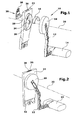
- eine schematische perspektivische Explosionsdarstellung eines erfindungsgemäßen berührungslosen Füllstandgebers,
- Fig. 2
- eine schematische perspektivische Ansicht des Füllstandgebers aus Fig. 1,
- Fig. 3
- eine schematische Schnittansicht einer ersten Ausführungsform eines erfindungsgemäßen Sensorelements in eingebautem Zustand,
- Fig. 4
- eine schematische Schnittansicht einer zweiten Ausführungsform des eingebauten Sensorelements,
- Fig. 5
- eine schematische Schnittansicht einer dritten Ausführungsform des eingebauten Sensorelements,
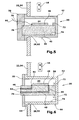
- Fig. 6
- eine schematische Schnittansicht einer vierten Ausführungsform des eingebauten Sensorelements, und
- Fig. 7
- eine schematische Schnittansicht einer fünften Ausführungsform des eingebauten Sensorelementes.
- Fig. 1:
- a schematic perspective exploded view of a non-contact level sensor according to the invention,
- Fig. 2
- 1 is a schematic perspective view of the level sensor of FIG. 1,
- Fig. 3
- a schematic sectional view of a first embodiment of a sensor element according to the invention in the installed state,
- Fig. 4
- a schematic sectional view of a second embodiment of the built-in sensor element,
- Fig. 5
- a schematic sectional view of a third embodiment of the built-in sensor element,
- Fig. 6
- a schematic sectional view of a fourth embodiment of the built-sensor element, and
- Fig. 7
- a schematic sectional view of a fifth embodiment of the built-in sensor element.
Der erfindungsgemäße berührungslose Füllstandgeber 10 weist einen Hebel 12
auf, der mit einem Schwimmer 14 und einem Magneten 16, der insbesondere als
Segment eines Ringmagneten ausgeführt ist, verbunden ist. Der Magnet 16 ist
mittelbar über ein erstes Gehäuseteil 18 mit dem Hebel 12 verbunden. Der
Hebel 12 ist zusammen mit dem ersten Gehäuseteil 18 und dem Magneten 16
um eine Drehachse 20 schwenkbar mit einem Zwischenstück 22 verbunden. Das
Zwischenstück 22 weist einen rohrförmigen Fortsatz 24 auf, über den der Hebel
12 gelagert ist. Hierzu weist der Hebel 12 bzw. das erste Gehäuseteil 18 einen
Bolzen auf, der beispielsweise durch Klipsen mit dem Fortsatz 24 drehbar
verbunden ist. Zur zusätzlichen Stabilisierung der Drehbewegung des Hebels 12
weist das Zwischenstück 22 einen zweiten Gehäuseteil 26 auf, der das erste
Gehäuseteil 18 abstützt. Gleichzeitig halten das erste Gehäuseteil 18 und das
zweite Gehäuseteil 26 Kraftstoff, der gegen den Füllstandgeber spritzen könnte,
davon ab, in das Innere der Gehäuseteile 18, 26 einzudringen.The
Das Zwischenstück 22 weist ferner eine Öffnung 28 zur Aufnahme eines
Sensorelements 30 auf. Das Sensorelement 30 ist durch die Öffnung 28 derart
angeordnet, dass es sich zwischen dem Magneten 16 und der Drehachse 20
befindet und das von dem Magneten 16 erzeugte Magnetfeld weitestgehend
hysteresefrei misst. Das Zwischenstück 22 weist ferner ein Verbindungselement
32 auf, um den Füllstandgeber 10 mit einem Kraftstofftank 34 zu verbinden.
Hierbei bildet das Zwischenstück 22 insbesondere einen Teil des Kraftstofftanks
34. Ggf. weist das Zwischenstück eine Durchführöffnung 36 auf, um elektrische
Anschlüsse 38 des Sensorelements 30 zu einer Spannungsquelle bzw. einer
Auswerteeinheit hindurchzuführen. In der Auswerteeinheit kann die von dem
Sensorelement 30 aufgenommene Kennlinie weitverarbeitet werden, indem die
Kennlinie beispielsweise programmiert und/ oder kalibriert wird.The
In der ersten Ausführungsform des Sensorelements 30 (Fig. 3) ist mit einem
Basiselement 40 ein metallisches Abdeckelement 42 verlötet. Innerhalb eines
durch das Basiselement 40 und das Abdeckelement 42 gebildeten,
abgekapselten Raums 44 ist ein Detektorelement 46 angeordnet. Bei dem
Detektorelement 46 kann es sich um ein Hallelement und/ oder einen AMR-Sensor
und/ oder einen GMR-Sensor handeln. Das Detektorelement 46 ist auf
dem keramischen Basiselement 40 aufgebracht. Das Basiselement 40 weist
Leiterkanäle 48 auf, die über Lötstellen 50 mit dem Detektorelement 46
verbunden sind.In the first embodiment of the sensor element 30 (FIG. 3) is provided with a
Base member 40 a
Das Sensorelement 30 ist in einer Öffnung geführt, bei der es sich um die
Öffnung 28 des Zwischenstücks 22 oder um eine Aufnahmeöffnung 52 des
Kraftstofftanks 34 handeln kann. Das Sensorelement 30 ist derart in der Öffnung
28 bzw. der Aufnahmeöffnung 52 geführt, dass das Detektorelement 46
innerhalb des Kraftstofftanks 34 angeordnet ist. Dadurch sind Leiterenden 54 der
Leiterkanäle 48 außerhalb des Kraftstofftanks 34 angeordnet, wodurch die
Leiterenden 54 außerhalb des Kraftstofftanks 34 in einer nicht aggressiven
Umgebung über Lötpunkte oder dgl. mit elektrischen Kabeln oder Anschlüssen
38 verlötet werden können. Das Abdeckelement 42 ist in Fig. 3 von rechts in die
Öffnung 28, 52 eingeführt. Zur Lagepositionierung weist das Abdeckelement 42
einen Absatz 56 auf, der als Anschlag die Einstecktiefe des Sensorelements 30
begrenzt. Dadurch ist es möglich, das Detektorelement 46 relativ zum Magneten
16 zueinander zentriert anzuordnen. Das Detektorelement 46 und der Magnet 16
sind also im Wesentlichen zueinander fluchtend ausgerichtet, so dass das
Detektorelement 46 in einem im Wesentlichen homogenen, störungsfreien
Magnetfeld angeordnet ist.The
In der zweiten Ausführungsform des Hallsensor-Elelements 30 (Fig. 4) weist als
Abdeckelement 42 Kontaktelemente 58 auf, die über elektrische Leiter 60 mit
dem Detektorelement 46 verbunden sind. Die Kontaktelemente 58 sind jeweils
mit einem elektrischen Anschluss 38, beispielsweise durch Löten, verbunden. Die
Kontaktelemente 58 sind mit Hilfe eines Isolationsmittels 62 von dem übrigen
Abdeckelement 42 isoliert ausgeführt, so dass Kurzschlüsse vermieden sind. In the second embodiment of the Hall sensor element 30 (FIG. 4),
Das Abdeckelement 42 weist einen Ansatz 64 auf, der zu einer Oberfläche 66
des Abdeckelements 42 rechtwinklig ausgeführt ist. Es ergibt sich also zwischen
dem Ansatz 64 und der Oberfläche 66 ein rechter Winkel 68. Bei der Montage
wird das Sensorelement 30 in Fig. 4 von links in die Öffnung 28, 52 eingeführt,
so dass der Ansatz 64 als Anschlag die Einstecktiefe begrenzt. Auf Grund des
rechten Winkels 68 steht im eingebauten Zustand sowohl der Ansatz 64 als auch
die Oberfläche 66 in Kontakt mit dem Zwischenstück 22 bzw. dem Kraftstofftank
34.The
In der dritten Ausführungsform des Sensorelements 30 (Fig. 5) weist das
Sensorelement 30 eine Abdeckkapsel auf, die aus dem Abdeckelement 42 und
einem Deckel 70 besteht. Das Basiselement 40 ist vollständig innerhalb der
Abdeckkapsel angeordnet. Das Abdeckelement 42 weist eine Nase 72 auf, die zu
einem Boden 74 des Abdeckelements 42 einen Abstand aufweist, der mit der
Dicke des Basiselements 40 korrespondiert. Dadurch ist es möglich, das
Basiselement 40 lagefixiert mit dem Abdeckelement zu verbinden, so dass ein
Verlöten entfallen kann. Entsprechend weist der Deckel 70 eine Vertiefung 76
auf, die ebenfalls mit der Dicke des Basiselements 40 korrespondiert. Das
Basiselement 40 wird also sowohl von dem Abdeckelement 42 als auch von dem
Deckel 70 gehalten.In the third embodiment of the sensor element 30 (
Der Deckel 70 und das Abdeckelement 42 sind vorzugsweise stoffschlüssig,
insbesondere durch Löten, miteinander verbunden. Um das Detektorelement 46
mit einer Auswerteeinheit bzw. einer Spannungsquelle zu verbinden, weist der
Deckel 70 ferner einer Verbindungsöffnung 78 auf, durch welche die Leiter 60
hindurchgeführt werden können.The
In der vierten Ausführungsform des Sensorelements 30 (Fig. 6) wird das
Basiselement 40, das Leiterkanäle 48 aufweist, durch eine entsprechend groß
ausgeführte Verbindungsöffnung 78 des Deckels 70 geführt, so dass die
Leiterenden 54 außerhalb des Kraftstofftanks 34 angeordnet sind. Im Vergleich
zu der in Fig. 5 dargestellten Ausführungsform des Sensorelements 30 ist die
Vertiefung 76 durch den Deckel 70 hindurch als Verbindungsöffnung 78
ausgeführt, wodurch ein Bearbeitungsschritt für die Herstellung des Deckels 70
eingespart wird.In the fourth embodiment of the sensor element 30 (FIG. 6), the
Das Sensorelement 30 kann im Vergleich zu den vorherigen Ausführungsformen
auch um 90° gedreht eingebaut sein (Fig. 7). Diese Anordnung des
Sensorelementes 30 bietet sich insbesondere an, wenn als Detektorelement 46
ein AMR-/ GMR-Sensor verwendet wird. Das Detektorelement 46 und der
Magnet 16 sind vorzugsweise mittig zu der Drehachse 20 angeordnet, so dass
sich bei einer Drehung des Magneten 16 in Richtung eines Pfeils 80 die Richtung
des von dem Magneten 16 erzeugten Magnetfelds ändert. Die Änderung der
Magnetfeldrichtung wird durch das Detektorelement 46 detektiert. In dieser
Anordnung kann der Füllstandsgeber 10 beispielsweise anstatt des ersten
deckelförmigen Gehäuseteils 18 eine Drehwelle 82 aufweisen, mit welcher der
Magnet 16 verbunden ist. Insbesondere kann es sich bei dem Magneten 16 in
dieser Ausführungsform um einen Stabmagneten handeln, so dass eine
ringförmige Ausführung nicht erforderlich ist. Ferner kann das Sensorelement 30
an seiner Rückseite, d. h. an der vom Magneten 16 weg gerichteten Seite, mit
einer Folie, insbesondere Klebefolie, verbunden sein. Dadurch kann das
Sensorelement 30 besonders einfach mit dem Zwischenstück 22 bzw. dem
Kraftstofftank 34 verbunden werden.The
Claims (11)
einem aus einem elektrischen Isolatormaterial bestehenden Basiselement (40),
einem mit dem Basiselement (40) verbundenen Detektorelement (46),
einem von dem Detektorelement (46) beabstandet mit dem Basiselement (40) verbundenen, metallischen Abdeckelement (42), und
mit dem Detektorelement (46) verbundenen und durch das Abdeckelement (42) und/ oder das Basiselement (40) geführte elektrische Leiter (60) zur Verbindung mit einer Spannungsquelle bzw. einer Auswerteeinheit.Sensor element for measuring a magnetic field generated by a movable magnet (16), with
a base element (40) made of an electrical insulator material,
a detector element (46) connected to the base element (40),
one of the detector element (46) spaced from the base member (40) connected, metallic cover member (42), and
connected to the detector element (46) and guided by the cover (42) and / or the base member (40) electrical conductor (60) for connection to a voltage source or an evaluation unit.
einem drehbar gelagerten Hebel (12), der mit einem Schwimmer (14) und einem Magneten (16) verbunden ist, und
einem Sensorelement (30) nach einem der Ansprüche 1 - 9,
wobei der mit dem Hebel (12) verbundene Magnet (16) zwischen dem Sensorelement (30) und einer Drehachse (20) des Hebels (12) derart angeordnet ist, dass in Abhängigkeit von der Position des Schwimmers (14) sich das von dem Sensorelement (30) gemessene magnetische Feld ändert. Non-contact level sensor, in particular for a fuel tank (34) in a motor vehicle, with
a rotatably mounted lever (12) which is connected to a float (14) and a magnet (16), and
a sensor element (30) according to one of claims 1 - 9,
wherein the magnet (16) connected to the lever (12) is arranged between the sensor element (30) and an axis of rotation (20) of the lever (12) such that, depending on the position of the float (14), that of the sensor element (30) measured magnetic field changes.
Applications Claiming Priority (2)
| Application Number | Priority Date | Filing Date | Title |
|---|---|---|---|
| DE10360406 | 2003-12-19 | ||
| DE10360406A DE10360406B3 (en) | 2003-12-19 | 2003-12-19 | Hall effect sensor for vehicle fuel tank level gauge, measures field from moving magnet and is connected by lead to supply or evaluation instrument |
Publications (1)
| Publication Number | Publication Date |
|---|---|
| EP1544586A1 true EP1544586A1 (en) | 2005-06-22 |
Family
ID=34112169
Family Applications (1)
| Application Number | Title | Priority Date | Filing Date |
|---|---|---|---|
| EP04026987A Withdrawn EP1544586A1 (en) | 2003-12-19 | 2004-11-12 | Sensor element |
Country Status (3)
| Country | Link |
|---|---|
| US (1) | US7315165B2 (en) |
| EP (1) | EP1544586A1 (en) |
| DE (1) | DE10360406B3 (en) |
Cited By (3)
| Publication number | Priority date | Publication date | Assignee | Title |
|---|---|---|---|---|
| DE102006057307A1 (en) * | 2006-12-05 | 2008-06-12 | Tyco Electronics Amp Gmbh | Filling level measuring device for fuel tank, has position transmitter connected float element and position sensor cooperating with position transmitter in contactless manner |
| FR3105404A1 (en) | 2019-12-20 | 2021-06-25 | Renault S.A.S | Device for estimating the volume of liquid and method of implementing the device |
| US11084039B2 (en) | 2006-02-07 | 2021-08-10 | Stokes Bio Ltd. | Microfluidic analysis system |
Families Citing this family (31)
| Publication number | Priority date | Publication date | Assignee | Title |
|---|---|---|---|---|
| US7382585B1 (en) * | 2005-09-30 | 2008-06-03 | Storage Technology Corporation | Magnetic head having AMR reader, writer, and GMR reader |
| DE102005047467B4 (en) * | 2005-10-14 | 2011-09-01 | Continental Automotive Gmbh | level sensor |
| DE102005061707A1 (en) * | 2005-12-21 | 2007-06-28 | Ab Elektronik Gmbh | Rotation angle sensor |
| WO2009039290A2 (en) | 2007-09-20 | 2009-03-26 | Bradley Fixtures Corporation | Lavatory system |
| DE102007047295A1 (en) * | 2007-10-02 | 2009-04-09 | Kolektor Kautt & Bux Gmbh | Winding connection device for e.g. electric motor, has circuit board and connecting line sealed within body in relation to environmental influence, and contact point of connecting line contacted from outside of body |
| DE102007053877B3 (en) * | 2007-11-09 | 2009-04-16 | Voith Patent Gmbh | Gate valve for controlling working cylinders or servomotors |
| US8587297B2 (en) * | 2007-12-04 | 2013-11-19 | Infineon Technologies Ag | Integrated circuit including sensor having injection molded magnetic material |
| US20110187359A1 (en) * | 2008-05-30 | 2011-08-04 | Tobias Werth | Bias field generation for a magneto sensor |
| US8610430B2 (en) | 2008-05-30 | 2013-12-17 | Infineon Technologies Ag | Bias field generation for a magneto sensor |
| US8174256B2 (en) * | 2008-05-30 | 2012-05-08 | Infineon Technologies Ag | Methods and systems for magnetic field sensing |
| US8058870B2 (en) * | 2008-05-30 | 2011-11-15 | Infineon Technologies Ag | Methods and systems for magnetic sensing |
| WO2011044247A1 (en) | 2009-10-07 | 2011-04-14 | Bradley Fixtures Corporation | Lavatory system with hand dryer |
| EP2332600A1 (en) * | 2009-12-09 | 2011-06-15 | F. Hoffmann-La Roche AG | A method of filling a container with a liquid drug |
| US9267736B2 (en) | 2011-04-18 | 2016-02-23 | Bradley Fixtures Corporation | Hand dryer with point of ingress dependent air delay and filter sensor |
| US9170148B2 (en) | 2011-04-18 | 2015-10-27 | Bradley Fixtures Corporation | Soap dispenser having fluid level sensor |
| US9758953B2 (en) | 2012-03-21 | 2017-09-12 | Bradley Fixtures Corporation | Basin and hand drying system |
| US10100501B2 (en) | 2012-08-24 | 2018-10-16 | Bradley Fixtures Corporation | Multi-purpose hand washing station |
| DE102013215015A1 (en) * | 2013-07-31 | 2015-02-05 | Robert Bosch Gmbh | Measuring device for filling level of a container |
| US9488515B2 (en) | 2014-03-24 | 2016-11-08 | Deringer-Ney, Inc. | Apparatuses and methods for fuel level sensing |
| US9435680B2 (en) | 2014-03-24 | 2016-09-06 | Deringer-Ney, Inc. | Apparatuses and methods for fuel level sensing |
| JP6344221B2 (en) * | 2014-12-04 | 2018-06-20 | 株式会社デンソー | Liquid level detector |
| JP6344222B2 (en) * | 2014-12-04 | 2018-06-20 | 株式会社デンソー | Liquid level detector |
| JP6344226B2 (en) * | 2014-12-12 | 2018-06-20 | 株式会社デンソー | Liquid level detector |
| JP6336923B2 (en) * | 2015-01-30 | 2018-06-06 | 愛三工業株式会社 | Liquid level detector |
| JP6336924B2 (en) * | 2015-02-04 | 2018-06-06 | 愛三工業株式会社 | Liquid level detector |
| JP6336925B2 (en) * | 2015-02-05 | 2018-06-06 | 愛三工業株式会社 | Liquid level detector |
| DE102015224047A1 (en) * | 2015-12-02 | 2017-06-08 | Ti Automotive Technology Center Gmbh | level sensor |
| US10041236B2 (en) | 2016-06-08 | 2018-08-07 | Bradley Corporation | Multi-function fixture for a lavatory system |
| US11015329B2 (en) | 2016-06-08 | 2021-05-25 | Bradley Corporation | Lavatory drain system |
| JP6533807B2 (en) * | 2017-05-25 | 2019-06-19 | 矢崎総業株式会社 | Liquid level sensor |
| DE102019203825B4 (en) * | 2019-03-20 | 2023-07-06 | Vitesco Technologies GmbH | Angle detection device and fuel level detection device |
Citations (5)
| Publication number | Priority date | Publication date | Assignee | Title |
|---|---|---|---|---|
| US5637995A (en) * | 1992-12-09 | 1997-06-10 | Nippondenso Co., Ltd. | Magnetic detection device having a magnet including a stepped portion for eliminating turbulence at the MR sensor |
| US6199428B1 (en) * | 1998-09-22 | 2001-03-13 | Siemens Aktiengesellschaft | Fluid level measuring device |
| DE19951342A1 (en) * | 1999-10-25 | 2001-04-26 | Schulz & Rackow Gastechnik Gmb | Filling level display; has flange with tube having float rod with giant magnetoresistance non-contact sensor opposite magnetic part of float rod joint and magnetically controlled display unit |
| US20020043105A1 (en) * | 2000-07-21 | 2002-04-18 | Beck Charles W. | Liquid level measurement and fuel transducer using anisotropic magnetoresistance device |
| DE10142618A1 (en) * | 2001-08-31 | 2003-03-27 | Helag Electronic Gmbh | Measurement of fluid level in a tank using a pivoting float arm and a magnetic contact-free sensor arrangement for measuring the pivot position of the float arm relative to the tank |
Family Cites Families (3)
| Publication number | Priority date | Publication date | Assignee | Title |
|---|---|---|---|---|
| JPH0442559Y2 (en) | 1985-10-03 | 1992-10-07 | ||
| US4920797A (en) * | 1989-01-09 | 1990-05-01 | Schaevitz Sensing Systems, Inc. | Fluid level sensor |
| DE19701246A1 (en) * | 1997-01-16 | 1998-07-23 | Mannesmann Vdo Ag | Level sensor |
-
2003
- 2003-12-19 DE DE10360406A patent/DE10360406B3/en not_active Expired - Lifetime
-
2004
- 2004-11-12 EP EP04026987A patent/EP1544586A1/en not_active Withdrawn
- 2004-11-18 US US10/992,637 patent/US7315165B2/en active Active
Patent Citations (5)
| Publication number | Priority date | Publication date | Assignee | Title |
|---|---|---|---|---|
| US5637995A (en) * | 1992-12-09 | 1997-06-10 | Nippondenso Co., Ltd. | Magnetic detection device having a magnet including a stepped portion for eliminating turbulence at the MR sensor |
| US6199428B1 (en) * | 1998-09-22 | 2001-03-13 | Siemens Aktiengesellschaft | Fluid level measuring device |
| DE19951342A1 (en) * | 1999-10-25 | 2001-04-26 | Schulz & Rackow Gastechnik Gmb | Filling level display; has flange with tube having float rod with giant magnetoresistance non-contact sensor opposite magnetic part of float rod joint and magnetically controlled display unit |
| US20020043105A1 (en) * | 2000-07-21 | 2002-04-18 | Beck Charles W. | Liquid level measurement and fuel transducer using anisotropic magnetoresistance device |
| DE10142618A1 (en) * | 2001-08-31 | 2003-03-27 | Helag Electronic Gmbh | Measurement of fluid level in a tank using a pivoting float arm and a magnetic contact-free sensor arrangement for measuring the pivot position of the float arm relative to the tank |
Cited By (4)
| Publication number | Priority date | Publication date | Assignee | Title |
|---|---|---|---|---|
| US11084039B2 (en) | 2006-02-07 | 2021-08-10 | Stokes Bio Ltd. | Microfluidic analysis system |
| DE102006057307A1 (en) * | 2006-12-05 | 2008-06-12 | Tyco Electronics Amp Gmbh | Filling level measuring device for fuel tank, has position transmitter connected float element and position sensor cooperating with position transmitter in contactless manner |
| DE102006057307B4 (en) * | 2006-12-05 | 2011-08-25 | Tyco Electronics AMP GmbH, 64625 | Level measuring device for a fuel tank |
| FR3105404A1 (en) | 2019-12-20 | 2021-06-25 | Renault S.A.S | Device for estimating the volume of liquid and method of implementing the device |
Also Published As
| Publication number | Publication date |
|---|---|
| DE10360406B3 (en) | 2005-03-03 |
| US20050146323A1 (en) | 2005-07-07 |
| US7315165B2 (en) | 2008-01-01 |
Similar Documents
| Publication | Publication Date | Title |
|---|---|---|
| EP1544586A1 (en) | Sensor element | |
| DE102007007840B4 (en) | Rotation detecting device | |
| DE102007018758B4 (en) | angle sensor | |
| EP2867684B1 (en) | Arrangement for measuring current | |
| DE102004006298B4 (en) | Connecting arrangement for a measuring element of a battery sensor | |
| EP2366096B1 (en) | Assembly set for an electric motor with an angle sensor | |
| WO2009092479A1 (en) | Magnetic field sensor | |
| DE102012206959A1 (en) | Magnetic sensing device | |
| DE10007868B4 (en) | Electronic control circuit | |
| EP1644749A1 (en) | Sensor unit for an on-board network of a motor vehicle, and method for the production of a sensor unit | |
| DE4320939A1 (en) | poetry | |
| DE102006031139A1 (en) | Connecting device for contactless measurement of linear position of rotor, has pair of triangular coils of same surface with form depicts square in former level and another pair of coils of same surface with form arranged in later level | |
| DE102010020119B4 (en) | magnetic field sensor | |
| DE4219923C2 (en) | Magnet sensor | |
| DE10108377C1 (en) | Steering column module, for providing washing and/or steering angle detection functions in automobile, has several function units combined with electronic unit for processing and/or combining their output signals | |
| DE102017212039B4 (en) | Rotation angle measuring device | |
| EP2871447B1 (en) | Arrangement for monitoring a component rotating around its axis with a rotational speed sensor and a temperature sensor | |
| DE19744673C2 (en) | Device for detecting the speed of a rotating component, in particular for a motor vehicle | |
| WO2008098954A1 (en) | Modular measuring device | |
| DE102006050177A1 (en) | Magnetic field sensor e.g. rotational speed sensor, for e.g. vehicle wheel, has carrier designed as plastic-injected part and provided for magnetic field-sensitive sensor unit, which is designed as surface mount device unit | |
| DE102009000225A1 (en) | Battery for use with energy management system of motor vehicle, has integrated current sensor i.e. flux gate sensor, that is connected with electronic evaluation circuit over resumed measuring lines | |
| DE102008003338A1 (en) | Electric current determining device for use in cable i.e. earth cable, has cable provided with cable insulation, where cable insulation is formed such that cable insulation partially encloses measuring element and/or electronic system | |
| WO2017045683A1 (en) | Connection device for a camera module, camera module as well as method for contacting a camera module | |
| DE102007047295A1 (en) | Winding connection device for e.g. electric motor, has circuit board and connecting line sealed within body in relation to environmental influence, and contact point of connecting line contacted from outside of body | |
| DE102015205872A1 (en) | Electronic module of an actuator with cover element for better alignment of sensor and rotor magnet |
Legal Events
| Date | Code | Title | Description |
|---|---|---|---|
| PUAI | Public reference made under article 153(3) epc to a published international application that has entered the european phase |
Free format text: ORIGINAL CODE: 0009012 |
|
| AK | Designated contracting states |
Kind code of ref document: A1 Designated state(s): AT BE BG CH CY CZ DE DK EE ES FI FR GB GR HU IE IS IT LI LU MC NL PL PT RO SE SI SK TR |
|
| AX | Request for extension of the european patent |
Extension state: AL LT LV MK |
|
| 17P | Request for examination filed |
Effective date: 20050630 |
|
| AKX | Designation fees paid |
Designated state(s): DE FR IT |
|
| 17Q | First examination report despatched |
Effective date: 20070614 |
|
| STAA | Information on the status of an ep patent application or granted ep patent |
Free format text: STATUS: THE APPLICATION IS DEEMED TO BE WITHDRAWN |
|
| 18D | Application deemed to be withdrawn |
Effective date: 20071225 |