EP1544473A2 - Ultra-high speed vacuum pump system with first stage turbofan and second stage turbomolecular pump - Google Patents
Ultra-high speed vacuum pump system with first stage turbofan and second stage turbomolecular pump Download PDFInfo
- Publication number
- EP1544473A2 EP1544473A2 EP04029460A EP04029460A EP1544473A2 EP 1544473 A2 EP1544473 A2 EP 1544473A2 EP 04029460 A EP04029460 A EP 04029460A EP 04029460 A EP04029460 A EP 04029460A EP 1544473 A2 EP1544473 A2 EP 1544473A2
- Authority
- EP
- European Patent Office
- Prior art keywords
- turbofan
- fluid stream
- shaft
- stage
- fluid
- Prior art date
- Legal status (The legal status is an assumption and is not a legal conclusion. Google has not performed a legal analysis and makes no representation as to the accuracy of the status listed.)
- Withdrawn
Links
- 239000012530 fluid Substances 0.000 claims abstract description 79
- 238000005086 pumping Methods 0.000 claims abstract description 28
- 230000006835 compression Effects 0.000 claims abstract description 18
- 238000007906 compression Methods 0.000 claims abstract description 18
- 238000000034 method Methods 0.000 claims description 22
- 230000005291 magnetic effect Effects 0.000 claims description 14
- 230000007246 mechanism Effects 0.000 claims description 7
- 230000002159 abnormal effect Effects 0.000 claims description 4
- 239000002245 particle Substances 0.000 abstract description 5
- 238000013461 design Methods 0.000 description 12
- 230000008569 process Effects 0.000 description 9
- 239000000463 material Substances 0.000 description 7
- 238000004891 communication Methods 0.000 description 6
- 239000007789 gas Substances 0.000 description 5
- 238000010943 off-gassing Methods 0.000 description 4
- 238000009987 spinning Methods 0.000 description 4
- 230000006641 stabilisation Effects 0.000 description 4
- 238000011105 stabilization Methods 0.000 description 4
- RTAQQCXQSZGOHL-UHFFFAOYSA-N Titanium Chemical compound [Ti] RTAQQCXQSZGOHL-UHFFFAOYSA-N 0.000 description 3
- 238000010586 diagram Methods 0.000 description 3
- 238000005516 engineering process Methods 0.000 description 3
- 239000007788 liquid Substances 0.000 description 3
- 229910052719 titanium Inorganic materials 0.000 description 3
- 239000010936 titanium Substances 0.000 description 3
- 238000011144 upstream manufacturing Methods 0.000 description 3
- 229910000831 Steel Inorganic materials 0.000 description 2
- 230000001133 acceleration Effects 0.000 description 2
- 230000008901 benefit Effects 0.000 description 2
- 238000010276 construction Methods 0.000 description 2
- 238000011109 contamination Methods 0.000 description 2
- 238000009792 diffusion process Methods 0.000 description 2
- 230000004941 influx Effects 0.000 description 2
- 238000012423 maintenance Methods 0.000 description 2
- 238000012986 modification Methods 0.000 description 2
- 230000004048 modification Effects 0.000 description 2
- 230000008439 repair process Effects 0.000 description 2
- 239000007787 solid Substances 0.000 description 2
- 239000010959 steel Substances 0.000 description 2
- OKTJSMMVPCPJKN-UHFFFAOYSA-N Carbon Chemical compound [C] OKTJSMMVPCPJKN-UHFFFAOYSA-N 0.000 description 1
- UFHFLCQGNIYNRP-UHFFFAOYSA-N Hydrogen Chemical compound [H][H] UFHFLCQGNIYNRP-UHFFFAOYSA-N 0.000 description 1
- HLCFGWHYROZGBI-JJKGCWMISA-M Potassium gluconate Chemical compound [K+].OC[C@@H](O)[C@@H](O)[C@H](O)[C@@H](O)C([O-])=O HLCFGWHYROZGBI-JJKGCWMISA-M 0.000 description 1
- 101710112672 Probable tape measure protein Proteins 0.000 description 1
- 101710204224 Tape measure protein Proteins 0.000 description 1
- 230000009471 action Effects 0.000 description 1
- XAGFODPZIPBFFR-UHFFFAOYSA-N aluminium Chemical compound [Al] XAGFODPZIPBFFR-UHFFFAOYSA-N 0.000 description 1
- 229910052782 aluminium Inorganic materials 0.000 description 1
- 230000000712 assembly Effects 0.000 description 1
- 238000000429 assembly Methods 0.000 description 1
- -1 but not limited to Substances 0.000 description 1
- 229910052799 carbon Inorganic materials 0.000 description 1
- 239000000919 ceramic Substances 0.000 description 1
- 230000003749 cleanliness Effects 0.000 description 1
- 230000000052 comparative effect Effects 0.000 description 1
- 230000001066 destructive effect Effects 0.000 description 1
- 230000005292 diamagnetic effect Effects 0.000 description 1
- 239000002889 diamagnetic material Substances 0.000 description 1
- 229910003460 diamond Inorganic materials 0.000 description 1
- 239000010432 diamond Substances 0.000 description 1
- 230000001747 exhibiting effect Effects 0.000 description 1
- 239000011888 foil Substances 0.000 description 1
- 230000004927 fusion Effects 0.000 description 1
- 239000004519 grease Substances 0.000 description 1
- 229910052739 hydrogen Inorganic materials 0.000 description 1
- 239000001257 hydrogen Substances 0.000 description 1
- 238000002955 isolation Methods 0.000 description 1
- 238000005461 lubrication Methods 0.000 description 1
- 230000007257 malfunction Effects 0.000 description 1
- 238000004519 manufacturing process Methods 0.000 description 1
- 238000012545 processing Methods 0.000 description 1
- 230000008929 regeneration Effects 0.000 description 1
- 238000011069 regeneration method Methods 0.000 description 1
- 230000035939 shock Effects 0.000 description 1
- 238000004088 simulation Methods 0.000 description 1
- 239000003381 stabilizer Substances 0.000 description 1
Images

Classifications
-
- F—MECHANICAL ENGINEERING; LIGHTING; HEATING; WEAPONS; BLASTING
- F04—POSITIVE - DISPLACEMENT MACHINES FOR LIQUIDS; PUMPS FOR LIQUIDS OR ELASTIC FLUIDS
- F04D—NON-POSITIVE-DISPLACEMENT PUMPS
- F04D19/00—Axial-flow pumps
- F04D19/02—Multi-stage pumps
- F04D19/04—Multi-stage pumps specially adapted to the production of a high vacuum, e.g. molecular pumps
- F04D19/042—Turbomolecular vacuum pumps
Definitions
- the present invention relates to vacuum pumps for generating ultra-high vacuum within an evacuated chamber. More specifically, the present invention relates to a vacuum pump systems that include a first stage high-speed turbofan and a second stage turbomolecular pump, as well as a method of using the vacuum pump system.
- Turbomolecular pumps are widely employed for generating an ultra-high vacuum in an evacuated chamber.
- Vacuum pumps generally include turbo molecular pumps, drag pumps, centrifugal pumps, diffusion pumps, cryopumps, titanium sputter pumps, getter pumps and the like.
- turbomolecular pumps are employed to compress gases, such as hydrogen in the 10 -8 Pa (10 -10 Torr) range, to pressures for evacuation through roughing pumps (about 10 Pa).
- the principle underlying turbomolecular pumps is that in high vacuum, where the molecular mean free path of the remaining gas is large compared to the dimensions of the chamber, fast moving rotors impart a linear momentum to fluid particles that interact with the rotors.
- the relative velocity imparted to a fluid stream by the alternating rotating blades and stator blades draws the fluid from the vacuum chamber to be evacuated to the pump exhaust outlet.
- Each set of rotor blades and stator blades is able to support a pressure difference.
- the compression ratio for zero flow is approximately the product of the compression ratios for each set.
- Conventional turbomolecular pumps achieve high ratios of compression by operating at a high rotational speed and by employing a large number of rotor/stator blade sets.
- Turbomolecular pumps are available commercially for applications where pumping speeds of up to a few thousand liters per second (liter/sec) are required.
- Conventional turbomolecular pumps are ill-suited to achieving ultra high pumping speeds, however.
- Ultra high pumping speeds require very large diameter pumps. Large pump diameters are not compatible with reaching large compression ratios economically.
- Turbopump bearings must support the rapidly spinning rotor in high vacuum.
- the output stages can require reasonably high torque and power when starting a turbo pump. These requirements are harder to meet in a large diameter turbo pump.
- the required pumping speed sets the diameter size of the rotor, and requires a large diameter pump where ultra high speeds are needed.
- Certain applications require extremely high pumping speeds at ultra low pressures. Examples include space simulation chambers, fusion reactors, particle accelerators and detectors, large processing chambers such as mirror coaters, and experimental chambers such as LIGO interferometer arms or Kaon decay pipes.
- Turbomolecular pumps would be the pumps of choice for these applications.
- conventional turbomolecular pumps are designed for high compression rates and only moderate pumping velocities, because their designs become quite difficult when scaling up to ultra high pumping speeds.
- Disadvantages to using turbomolecular pumps in such situations include: acquisition cost, the need for bearing regeneration or replacement, maintenance costs such as bearing replacements, contamination of the process chamber.
- a turbofan preferably employed as an input stage in connection with a conventional turbomolecular pump, is characterized by ultra-high pumping speeds, preferably large diameters, and moderate compression.
- the turbofan comprises one or more stator and rotor blade sets contained in an impermeable housing or within the evacuation chamber itself.
- the rotor blades extend radially from a rotatable longitudinal shaft.
- the stator blades which alternate with the rotor blades, are fixed and extend from the pump housing toward the rotatable shaft.
- the stator blades are spaced longitudinally between the rotor blades.
- the rotor and stator blades may be contoured or grooved to promote directional fluid flow.
- the rotor blades of the present turbofan are capable of rotating at a high linear blade velocity, to impart an ultra high pumping speed to a fluid stream, while remaining stabilized and without requiring a large power source for blade operation.
- the present turbofan is preferably employed in a preexisting low pressure environment. In such an environment it is believed that this results in low axial forces exerted upon the rotors from the fluid stream to be evacuated. It is believed that because of the low axial forces, the present turbofan can preferably employ a passive magnetic bearing with a geometrical configuration in which a point contact stabilizes the longitudinal positioning of the shaft. Additionally, because relatively simple bearing components can be employed, the turbofan is capable of being very reliable and can thus be placed substantially or entirely within a process chamber.
- the rotor or stator fan blades can be equipped with a series of concentric crash wire rings on their surface. In cases of sudden large fluid influx, for example, due to vacuum vessel failure or operator error, the fan blades would be forced upstream with great force. The rotor blades would then contact the crash wires, which provide support and very rapid deceleration.
- the ultra high speed turbofan is preferably employed in, although not limited to, a vacuum pump evacuation system comprising one or more first stage turbofans, as described above, upstream from one or more second stage conventional turbomolecular pump. Roughing pumps and/or forepumps can also be employed in the vacuum pump evacuation system.
- Another aspect of the presently described technology is a method for evacuating a vacuum chamber comprising:
- a fluid stream is defined as meaning a gas stream, a liquid stream, a liquid stream in which solid particles are entrained or dispersed, and/or a gas stream in which liquid droplets and/or solid particles are entrained or dispersed.
- the present technology preferably acts upon a mostly or entirely gaseous fluid stream.
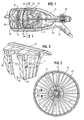
- Fig. 1 of the drawings Shown in Fig. 1 of the drawings is one embodiment of an ultra high speed vacuum pump turbofan 11, which is preferably employed as an ultra-high speed input stage, backed by a conventional turbomolecular pump.
- Turbofan 11 acts to draw a fluid stream into a turbofan inlet 12 and through to a turbofan outlet 13. Preferably, this outlet fluidly communicates with at least one additional turbofan or turbomolecular pump, as shown in Fig. 4 and Fig 5.
- the Turbofan inlet 12 fluidly communicates with an evacuation or process chamber 30, as shown in Fig. 4 and Fig. 5.
- Turbofan 11 is characterized by a ultra high pumping speed and moderate compression ratios.
- Typical pumping speeds are greater than 10,000 liters/second. More preferably, the pumping speeds are from 10,000 liters/second to 40,000 liters/second. In a preferred embodiment, turbofan 11 has a pumping speed of about 25,000 liters/second for a 1.0 meter diameter turbofan.
- Turbofan 11 need only have moderate compression ratios when preferably employed as the first stage in a vacuum pump evacuation system 10, with a conventional turbo-molecular pump 18 as a second stage, as shown in Fig. 4.
- Typical compression ratios are from about 1000x compression to 10x compression. More preferably, compression ratios range from 200x to 50x.
- a turbofan 11 with a modest 100x compression ratio and a 1 m diameter will have a pumping speed of about 25,000 liters/second for air and can be backed up by a 250 liters/second turbomolecular pump 18 placed behind an isolation valve of 15 centimeters diameter or less. Pressures well below 10 -8 Torr can be readily achieved with the present design.
- Turbofan 11 is preferably employed in a pre-existing high vacuum environment. Exceptional operation in a different environment is discussed below.
- the turbofan 11 can be disposed substantially or entirely within a process chamber, or connected fluidly to a process chamber, at a pressure that is held below at least about 10 -3 Pa. More preferably, the pre-existing low pressure is held below about 10 -5 Pa. Most preferably, the pre-existing low pressure is held below about 10 -6 Pa.
- the present ultra-high speed turbofan, evacuation system, and method are capable of further evacuating a chamber to pressures below 10 -8 Pa.
- the fluid forces on the rotor blades 17 are extremely small.
- the fluid forces are typically one millionth of a Newton per square meter or less. It is believed, while not limited to any particular theory, that this condition allows the use of a rotor blade 17 design, discussed below, characterized by a flexible or semi-flexible thin foil structure, which is stretched and kept in the required shape by the action of the centripetal force while the rotor is spinning. This design alternative offers the prospect of light weight and reduced cost of the turbofan.
- turbofan 11 is capable of utilizing larger diameters than conventional turbomolecular pumps.
- Typical turbofan 11 diameters are from about 0.1 meters to 3.0 meters. More preferably, the turbofan 11 diameter is from 0.5 to 1.5 meters. Most preferably, the turbofan 11 diameter is about 1 meter.
- Unencumbered by the need to compress gases to pressures that match the pump capability of the roughing pump, such turbofans would carry no large penalty in cost or complexity when going to the large diameters for ultra high pumping speeds.
- the large linear blade velocities that are required in turbo pumps can be reached at lower rotational speeds as the diameter becomes larger, which lowers stresses in the blades.
- turbofan 11 believed to be at least in part due to the small fluid forces, include the capability of utilizing a low power motor and inexpensive, relatively simple stabilization components, as discussed below.
- Turbofan 11 shown in Fig. 1 then, comprises one or more turbomolecular pump-like, turbine-like or fan-like stator blades 16 and rotor blades 17 contained in an impermeable housing 14, positioned adjacent to the evacuation or process chamber 30.
- turbofan 11 can be positioned directly in an evacuation or process chamber 30 as shown in Fig. 6. Because of the relatively simple, inexpensive, negligibly outgassing, and reliable components of the turbofan 11, it can be employed substantially or entirely within an evacuation or process chamber 30, as shown in Fig. 6. In this case, the turbofan will be significantly less costly than even a 1 meter diameter Ultra High Vacuum (UHV) valve.
- UHV Ultra High Vacuum
- Rotor blades 17 are mounted radially on a rotatable longitudinal shaft 15.
- Rotor blades 17 are preferably fan-like, turbomolecular-pump-like, or turbine-like except that a portion of the rotor blades, preferably from the rotational axis out to anywhere up to the half-radius, may be non-transparent to the fluid to inhibit fluid backflow.
- Shaft 15 is preferably held by at least one low friction or frictionless bearing 28. It is also preferable that shaft 15 is entirely contained within housing 14.
- Stator blades 16 meanwhile, are fixed blades extending from the pump housing 14 towards the rotatable shaft 15. Stator blades 16 are spaced longitudinally between rotor blades 17, as shown in Fig. 2. Stator blades 16 can be contoured and/or slanted to promote directional fluid flow. An example of grooved stator blades is shown in Fig. 3.
- Turbofan stator 16 and rotor blades 17 are preferably made from a lightweight, strong material. Such blades can be made from materials including, but not limited to, titanium, aluminum, and other materials employed in turbine based fans, industrial fans, and turbomolecular pumps. Rotor blades 17 are preferably composed of a material that maintains its shape when stopped, and resist forces due to centrifugal acceleration, rotational acceleration, and forces from the fluid flow and fluid pressure differences.
- Rotor blades 17 can touch stator 16 blade assemblies if motor 29 has sufficient torque to start shaft 15 and rotor blades 17 against that small friction force.
- Rotor blades 17 additionally are preferably thin and flexible such that they can be stabilized by centrifugal force when spinning. Further, rotor blades 17 preferably are sufficiently well balanced to satisfy bearing requirements.
- the turbofan is capable of being driven by a low power motor 29.
- rotatable shaft 15 and rotor blades 17 can be driven by a motor assembly suspended inside the housing 24 and cooled via small steel pipes.
- rotatable shaft 15 and rotors can be driven by an alternating current (AC) motor 29 with an enclosed or canned rotational component on the downstream end of the shaft 15 in the vacuum and a stationary component outside the vacuum envelope.
- AC alternating current
- This configuration has the advantage of leaving only non-contact, passive elements inside the vacuum envelope, enabling low outgassing, extreme reliability and an increased lifetime.
- an external motor can be employed, provided that sufficient hermetic seals are also employed to ensure that a high vacuum is maintained.
- the motor 29 is capable of operating at variable speeds.
- the motor may operate at a fixed speed.
- the present turbofan rotor blades 17 are capable of rotating at a high linear blade velocity to impart a high pumping speed while remaining stabilized and without requiring a large-capacity power source for stabilization assistance.
- Conventional turbomolecular pumps typically employ oiled or greased bearings that are vented to the high pressure side of the pump. Pumps with active or passive magnetic bearings are commercially available and are generally employed in oil-free applications. Such magnetic bearings are expensive, however, and are sometimes not as reliable as lubricated bearings due to the complexity of the active feedback system normally employed to center the rotational shaft and rotors. Additionally, turbomolecular pumps that are constructed using passive magnetic bearings are not normally stable in all degrees of freedom, however. Magnetic bearings, therefore, typically employ either an active feedback system or a design in which a conventional lubricated bearing stabilizes the magnetic bearing.
- a passive magnetic bearing 28 can be used that employs a geometrical configuration in which a point contact (including, but not limited to steel on a diamond plate) stabilizes the longitudinal positioning of the rotatable turbofan shaft 15. Stabilization of small axial forces can also be achieved using diamagnetic materials like carbon.
- a particularly preferred design employs a diamagnetic or dynamic repulsive stabilizer, backed by a point contact for large force occurrences.
- the point contact is, in turn, backed by a dry slide ring or dry ball bearing for very large forces such as can occur during air in-rush or a physical shock to the evacuation pump system.
- turbofan shaft 15 is preferably held in place by a permanent magnetic bearing 28.
- An additional slip ring not normally contacting the shaft, can be employed to restrict shaft excursion during extreme force conditions.
- a vacuum pump be designed to survive a sudden and unexpected influx of fluid of such magnitude that normal operation cannot take place and fluid forces can become large and possibly destructive. Examples of such events are malfunction of or damage to the impermeable housing or the pump or the evacuation chamber and/or its appendages.
- turbofan 11 having preferably a large diameter to enable it to provide ultra high pumping speeds, is vulnerable to these fluid forces which occur under abnormal conditions, for example, when a large fluid mass invades the turbofan 11 while it is spinning at operating speed.
- the turbofan can be protected from damage due to such abnormal forces by adding crash protection devices, as shown in Fig. 3. While a turbofan can function well without crash protection devices, and can be on occasion employed without said devices, a preferable embodiment of a turbofan includes such devices.
- the primary fluid forces can be large enough to overstress blades of most designs.
- the preferred embodiment of the turbofan blades has blades of sufficient flexibility to flex under those forces, rather than breaking. When the blades flex they may touch the stator blades. The rotor and stator blades could enmesh and break.
- This device works by providing a slip surface between the each rotor 17 and the downstream stator blade assembly 16.
- the flexing rotor blades 17 ride on the slip surface for the brief time it takes for the rotor 17 to come to a halt.
- the slip surface is preferably mostly transparent to the fluid and is preferably constructed of vacuum compatible material.
- One possible embodiment uses a plurality of circular concentric wire rings as shown in Fig. 3, either as a free standing screen, or attached to and supported by the stator blade assembly.
- Fig. 4 shows the turbofan 11 in its preferred use in a system 10, as a first stage (that is, a precompression or pre-pump) ultra-high speed vacuum pump, upstream from a second stage conventional turbomolecular pump 18.
- First-stage turbofan 11 provides ultra high pumping speeds, with moderate compression, as indicated above, while second stage conventional turbomolecular pump 18 provides high compression pumping.
- the system shown in Fig. 4 comprises a first stage turbofan 11, as discussed above, fluidly connected to a chamber 30 to be evacuated.
- a hermetic valve can be employed at the connection point between the turbofan inlet 12 and the evacuation chamber outlet.
- first stage turbofan 11 can be disposed within the chamber to be evacuated, with an outlet port 13 extending from the evacuation chamber.
- a second stage conventional turbomolecular pump 18 can be connected in fluid communication with turbofan 11.
- a hermetic valve or seal can be employed at the junction between the turbofan outlet 13 and turbomolecular pump inlet 19.
- the turbomolecular pump 18, in turn, can be connected in fluid communication to a roughing pump 24, as shown in Fig. 5, or can vent to a second chamber or to atmosphere.
- a hermetic valve or seal can be employed at the junction between turbomolecular pump outlet 20 and roughing pump inlet 25.
- the roughing pump preferably then vents to atmosphere at a roughing pump outlet 26.
- the vacuum pump evacuation system 10 can employ additional pre-pumps or precompression pumps 21, locatable between the evacuation chamber 30 and turbofan 11. Additionally, the vacuum pump evacuation system 10 can employ additional backing pumps 26 after the conventional turbomolecular pump. Hermetic valves or seals can be employed at the junctions between the forepump inlet 22 and the evacuation chamber 30, and/or the forepump outlet 23 and turbofan inlet 12.
- the vacuum pump evacuation system can also employ more than one turbofan 11 as a back-up, multi-stage, or redundant fan, due to the comparative low materials cost of such a turbofan.
- the additional turbofans can be employed in series in the vacuum pump evacuation system, or as parallel components with or without hermetic bypass valves.
- the foregoing turbofan and vacuum pump system can evacuate a vacuum chamber in the following manner.
- the ultra high-speed turbofan 11 is disposed either downstream from the chamber 30 to be evacuated or substantially or entirely within it, and in fluid communication with the chamber 30.
- the chamber to be evacuated and the ultra-high speed turbofan are then maintained at a pre-existing low pressure, as described above.
- turbomolecular pump 18 is disposed downstream from turbofan 11, and is fluidly connected at its inlet port 19 to outlet port 13 of turbofan 11.
- this turbomolecular pump 18 is separated from the turbofan 11 by a hermetic valve.
- this valve remains closed when the system is not in operation, in order to maintain a pre-existing vacuum in the turbofan and chamber to be evacuated.
- the turbofan 11 itself may be evacuated before turbofan start-up.
- turbomolecular pump 18 Upon start-up of the turbofan 11, shaft 15 is rotated about its longitudinal axis such that rotor blades 17 cooperate with stator blades 16 to impart a velocity to a fluid stream drawn through the turbofan inlet 12 and exhausted at turbofan outlet 13. Thereafter, the fluid stream is further compressed and transferred downstream by turbomolecular pump 18. Additional forepumps and/or backing pumps can be employed, as described above.
Landscapes
- Engineering & Computer Science (AREA)
- Mechanical Engineering (AREA)
- General Engineering & Computer Science (AREA)
- Non-Positive Displacement Air Blowers (AREA)
- Structures Of Non-Positive Displacement Pumps (AREA)
Abstract
An ultra-high speed vacuum pump evacuation system (10) includes a first stage ultra-high speed turbofan (11) and a second stage conventional turbomolecular pump (18). The turbofan (11) is either connected in series to a chamber to be evacuated (30), or is optionally disposed entirely within the chamber. The turbofan (11) employs large diameter rotor blades (17) operating at high linear blade velocity to impart an ultra-high pumping speed to a fluid. The second stage turbomolecular pump (18) is fluidly connected downstream from the first stage turbofan (11). In operation, the first stage turbofan (11) operates in a pre-existing vacuum, with the fluid asserting only small axial forces upon the rotor blades (17). The turbofan (11) imparts a velocity to fluid particles towards an outlet (13) at a high volume rate, but moderate compression ratio. The second stage conventional turbomolecular pump (18) then compresses the fluid to pressures for evacuation by a roughing pump. <IMAGE>
Description
This invention was made with Government support under Contract No.
DE-AC02-76CH03000, awarded by the United States Department of Energy. The
Government has certain rights in the invention.
The present invention relates to vacuum pumps for generating ultra-high vacuum
within an evacuated chamber. More specifically, the present invention relates to a
vacuum pump systems that include a first stage high-speed turbofan and a second
stage turbomolecular pump, as well as a method of using the vacuum pump system.
Turbomolecular pumps (TMPs; sometimes also referred to as turbopumps) are widely
employed for generating an ultra-high vacuum in an evacuated chamber. Vacuum
pumps generally include turbo molecular pumps, drag pumps, centrifugal pumps,
diffusion pumps, cryopumps, titanium sputter pumps, getter pumps and the like. In
general, turbomolecular pumps are employed to compress gases, such as hydrogen
in the 10-8 Pa (10-10 Torr) range, to pressures for evacuation through roughing
pumps (about 10 Pa). The principle underlying turbomolecular pumps is that in high
vacuum, where the molecular mean free path of the remaining gas is large compared
to the dimensions of the chamber, fast moving rotors impart a linear momentum to
fluid particles that interact with the rotors. The relative velocity imparted to a fluid
stream by the alternating rotating blades and stator blades draws the fluid from the
vacuum chamber to be evacuated to the pump exhaust outlet. Each set of rotor
blades and stator blades is able to support a pressure difference. For a series of
blade sets, the compression ratio for zero flow is approximately the product of the
compression ratios for each set. Conventional turbomolecular pumps achieve high
ratios of compression by operating at a high rotational speed and by employing a
large number of rotor/stator blade sets.
With a high rotational speed and greater number of rotor/stator blade sets come
increased difficulties in manufacturing the pumps and in their maintenance and
repair, which increases overall operational costs.
Turbomolecular pumps are available commercially for applications where pumping
speeds of up to a few thousand liters per second (liter/sec) are required.
Conventional turbomolecular pumps are ill-suited to achieving ultra high pumping
speeds, however. Ultra high pumping speeds require very large diameter pumps.
Large pump diameters are not compatible with reaching large compression ratios
economically.
Turbopump bearings must support the rapidly spinning rotor in high vacuum. The
output stages can require reasonably high torque and power when starting a turbo
pump. These requirements are harder to meet in a large diameter turbo pump.
However, the required pumping speed sets the diameter size of the rotor, and
requires a large diameter pump where ultra high speeds are needed.
These partially conflicting demands limit the bearing design options and leads to
short bearing service life or reliance on complex electronics, for example to stabilize
a magnetic bearing.
Existing pumps use many bearing designs, including metallic and ceramic ball
bearings, with oil or grease lubrication; active and passive magnetic bearings; and
combinations thereof. Hence turbomolecular vacuum pumps are complex, and
expensive.
Certain applications require extremely high pumping speeds at ultra low pressures.
Examples include space simulation chambers, fusion reactors, particle accelerators
and detectors, large processing chambers such as mirror coaters, and experimental
chambers such as LIGO interferometer arms or Kaon decay pipes.
Turbomolecular pumps would be the pumps of choice for these applications.
However, conventional turbomolecular pumps are designed for high compression
rates and only moderate pumping velocities, because their designs become quite
difficult when scaling up to ultra high pumping speeds. Disadvantages to using
turbomolecular pumps in such situations include: acquisition cost, the need for
bearing regeneration or replacement, maintenance costs such as bearing
replacements, contamination of the process chamber.
Because of these disadvantages, diffusion pumps, cryopumps, titanium sputter
pumps and getter pumps are generally employed instead.
Thus, there is presently a need for an ultra high pumping speed vacuum evacuation
apparatus, system, and method capable of reaching ultra high vacuum. There is
additionally a need that such a vacuum evacuation apparatus be low cost, require
minimum repair, have very high reliability, and have a very long life.
The above and other shortcomings are overcome by the present ultra high-speed
vacuum pump turbofan, vacuum pump system that includes an ultra high-speed
turbofan input stage backed by a conventional turbomolecular pump, and a method
of using the same. Embodiments of the present vacuum pump system exhibit, but
are not limited to, one or more of the following advantageous operational features:
In one embodiment, a turbofan, preferably employed as an input stage in connection
with a conventional turbomolecular pump, is characterized by ultra-high pumping
speeds, preferably large diameters, and moderate compression. The turbofan
comprises one or more stator and rotor blade sets contained in an impermeable
housing or within the evacuation chamber itself. The rotor blades extend radially
from a rotatable longitudinal shaft. The stator blades, which alternate with the rotor
blades, are fixed and extend from the pump housing toward the rotatable shaft. The
stator blades are spaced longitudinally between the rotor blades. The rotor and stator
blades may be contoured or grooved to promote directional fluid flow.
The rotor blades of the present turbofan are capable of rotating at a high linear blade
velocity, to impart an ultra high pumping speed to a fluid stream, while remaining
stabilized and without requiring a large power source for blade operation.
The present turbofan is preferably employed in a preexisting low pressure
environment. In such an environment it is believed that this results in low axial
forces exerted upon the rotors from the fluid stream to be evacuated. It is believed
that because of the low axial forces, the present turbofan can preferably employ a
passive magnetic bearing with a geometrical configuration in which a point contact
stabilizes the longitudinal positioning of the shaft. Additionally, because relatively
simple bearing components can be employed, the turbofan is capable of being very
reliable and can thus be placed substantially or entirely within a process chamber.
Additionally, the rotor or stator fan blades can be equipped with a series of
concentric crash wire rings on their surface. In cases of sudden large fluid influx, for
example, due to vacuum vessel failure or operator error, the fan blades would be
forced upstream with great force. The rotor blades would then contact the crash
wires, which provide support and very rapid deceleration.
The ultra high speed turbofan is preferably employed in, although not limited to, a
vacuum pump evacuation system comprising one or more first stage turbofans, as
described above, upstream from one or more second stage conventional
turbomolecular pump. Roughing pumps and/or forepumps can also be employed in
the vacuum pump evacuation system.
Another aspect of the presently described technology is a method for evacuating a
vacuum chamber comprising:
In the present application, a fluid stream is defined as meaning a gas stream, a liquid
stream, a liquid stream in which solid particles are entrained or dispersed, and/or a
gas stream in which liquid droplets and/or solid particles are entrained or dispersed.
The present technology preferably acts upon a mostly or entirely gaseous fluid
stream.
- Fig. 1
- is a perspective view showing an internal construction of a turbofan in accordance with one embodiment of the present apparatus system and method of use.
- Fig. 2
- is a partial sectional view showing the spatial relationship of the stator blades and rotor blades within a turbofan in accordance with at least one embodiment of the present apparatus, system and method of use.
- Fig. 3
- is a perspective view showing internal construction of a turbofan employing crash protection rings in accordance with at least one embodiment of the present apparatus, system and method of use.
- Fig. 4
- is a partial schematic block diagram of a high vacuum pumping system in accordance with at least one embodiment of the present apparatus, system, and method of use showing a turbofan stage in fluid communication with an evacuation chamber and backing turbo-molecular pump.
- Fig. 5
- is a partial schematic block diagram of a high vacuum pumping system in accordance with at least one embodiment of the present apparatus, system, and method of use, showing a turbofan stage in fluid communication with an evacuation chamber, forepump, turbo-molecular pump, and roughing pump.
- Fig. 6
- is a partial schematic block diagram of a high vacuum pumping system in accordance with at least one embodiment of the present apparatus, system, and method of use, showing a turbofan stage substantially disposed within an evacuation chamber.
Shown in Fig. 1 of the drawings is one embodiment of an ultra high speed vacuum
pump turbofan 11, which is preferably employed as an ultra-high speed input stage,
backed by a conventional turbomolecular pump. Turbofan 11 acts to draw a fluid
stream into a turbofan inlet 12 and through to a turbofan outlet 13. Preferably, this
outlet fluidly communicates with at least one additional turbofan or turbomolecular
pump, as shown in Fig. 4 and Fig 5. Also preferably, the Turbofan inlet 12 fluidly
communicates with an evacuation or process chamber 30, as shown in Fig. 4 and Fig.
5. Turbofan 11 is characterized by a ultra high pumping speed and moderate
compression ratios.
Typical pumping speeds are greater than 10,000 liters/second. More preferably, the
pumping speeds are from 10,000 liters/second to 40,000 liters/second. In a preferred
embodiment, turbofan 11 has a pumping speed of about 25,000 liters/second for a
1.0 meter diameter turbofan.
In one example, a turbofan 11 with a modest 100x compression ratio and a 1 m
diameter will have a pumping speed of about 25,000 liters/second for air and can be
backed up by a 250 liters/second turbomolecular pump 18 placed behind an isolation
valve of 15 centimeters diameter or less. Pressures well below 10-8 Torr can be
readily achieved with the present design.
The present ultra-high speed turbofan, evacuation system, and method, are capable of further evacuating a chamber to pressures below 10-8 Pa.
In a pre-existing high vacuum environment, the fluid forces on the rotor blades 17
are extremely small. The fluid forces are typically one millionth of a Newton per
square meter or less. It is believed, while not limited to any particular theory, that
this condition allows the use of a rotor blade 17 design, discussed below,
characterized by a flexible or semi-flexible thin foil structure, which is stretched and
kept in the required shape by the action of the centripetal force while the rotor is
spinning. This design alternative offers the prospect of light weight and reduced cost
of the turbofan.
Additionally, it is believed that the small axial forces upon the rotors 17 allow the use
of relatively simple, inexpensive, and reliable bearing designs, as discussed below.
Furthermore, it is believed that because of the small fluid forces exerted upon the
rotors, the turbofan 11 is capable of utilizing larger diameters than conventional
turbomolecular pumps. Typical turbofan 11 diameters are from about 0.1 meters to
3.0 meters. More preferably, the turbofan 11 diameter is from 0.5 to 1.5 meters.
Most preferably, the turbofan 11 diameter is about 1 meter. Unencumbered by the
need to compress gases to pressures that match the pump capability of the roughing
pump, such turbofans would carry no large penalty in cost or complexity when going
to the large diameters for ultra high pumping speeds. The large linear blade
velocities that are required in turbo pumps can be reached at lower rotational
speeds as the diameter becomes larger, which lowers stresses in the blades.
Other advantages of the turbofan 11, believed to be at least in part due to the small
fluid forces, include the capability of utilizing a low power motor and inexpensive,
relatively simple stabilization components, as discussed below.
Also attributable to the small fluid forces and small axial forces on the rotatable shaft
15 and rotor blades 17, the turbofan is capable of being driven by a low power motor
29. For example, rotatable shaft 15 and rotor blades 17 can be driven by a motor
assembly suspended inside the housing 24 and cooled via small steel pipes. More
preferably, rotatable shaft 15 and rotors can be driven by an alternating current (AC)
motor 29 with an enclosed or canned rotational component on the downstream end
of the shaft 15 in the vacuum and a stationary component outside the vacuum
envelope. This configuration has the advantage of leaving only non-contact, passive
elements inside the vacuum envelope, enabling low outgassing, extreme reliability
and an increased lifetime. Optionally, an external motor can be employed, provided
that sufficient hermetic seals are also employed to ensure that a high vacuum is
maintained. Preferably, the motor 29 is capable of operating at variable speeds.
Alternatively, the motor may operate at a fixed speed.
The present turbofan rotor blades 17 are capable of rotating at a high linear blade
velocity to impart a high pumping speed while remaining stabilized and without
requiring a large-capacity power source for stabilization assistance. Conventional
turbomolecular pumps typically employ oiled or greased bearings that are vented to
the high pressure side of the pump. Pumps with active or passive magnetic bearings
are commercially available and are generally employed in oil-free applications. Such
magnetic bearings are expensive, however, and are sometimes not as reliable as
lubricated bearings due to the complexity of the active feedback system normally
employed to center the rotational shaft and rotors. Additionally, turbomolecular
pumps that are constructed using passive magnetic bearings are not normally stable
in all degrees of freedom, however. Magnetic bearings, therefore, typically employ
either an active feedback system or a design in which a conventional lubricated
bearing stabilizes the magnetic bearing.
It is believed, while not limited to any particular theory, that due to the small fluid
forces upon the rotors and the small axial force of the rotatable turbofan shaft 15
and rotor blades 17, a passive magnetic bearing 28 can be used that employs a
geometrical configuration in which a point contact (including, but not limited to steel
on a diamond plate) stabilizes the longitudinal positioning of the rotatable turbofan
shaft 15. Stabilization of small axial forces can also be achieved using diamagnetic
materials like carbon.
Another option that can be employed in the presently described technology is
dynamic repulsion of magnetic fields through the use of a conducting ring. A
particularly preferred design employs a diamagnetic or dynamic repulsive stabilizer,
backed by a point contact for large force occurrences. The point contact is, in turn,
backed by a dry slide ring or dry ball bearing for very large forces such as can occur
during air in-rush or a physical shock to the evacuation pump system.
The turbofan shaft 15, then, is preferably held in place by a permanent magnetic
bearing 28. An additional slip ring, not normally contacting the shaft, can be
employed to restrict shaft excursion during extreme force conditions.
By employing passive magnetic bearings with an optional stabilization point contact,
only non-contact, passive, low-outgassing components are located inside the vacuum
chamber. This results in low chamber contamination, high reliability and a longer
operational life. In addition, these bearing options are less expensive and more
reliable than those employed in conventional turbomolecular pumps.
Regardless of the specific design and material of the rotor blades, it is preferred that
a vacuum pump be designed to survive a sudden and unexpected influx of fluid of
such magnitude that normal operation cannot take place and fluid forces can become
large and possibly destructive. Examples of such events are malfunction of or
damage to the impermeable housing or the pump or the evacuation chamber and/or
its appendages.
It is believed that the turbofan 11, having preferably a large diameter to enable it to
provide ultra high pumping speeds, is vulnerable to these fluid forces which occur
under abnormal conditions, for example, when a large fluid mass invades the
turbofan 11 while it is spinning at operating speed.
The turbofan can be protected from damage due to such abnormal forces by adding
crash protection devices, as shown in Fig. 3. While a turbofan can function well
without crash protection devices, and can be on occasion employed without said
devices, a preferable embodiment of a turbofan includes such devices.
During abnormal operating events, the primary fluid forces can be large enough to
overstress blades of most designs. The preferred embodiment of the turbofan blades
has blades of sufficient flexibility to flex under those forces, rather than breaking.
When the blades flex they may touch the stator blades. The rotor and stator blades
could enmesh and break.
This can be prevented by the crash protection device as shown in Fig. 3. This device
works by providing a slip surface between the each rotor 17 and the downstream
stator blade assembly 16. The flexing rotor blades 17 ride on the slip surface for the
brief time it takes for the rotor 17 to come to a halt. The slip surface is preferably
mostly transparent to the fluid and is preferably constructed of vacuum compatible
material. One possible embodiment uses a plurality of circular concentric wire rings
as shown in Fig. 3, either as a free standing screen, or attached to and supported by
the stator blade assembly.
With the above-described embodiments and features of the turbofan 11 in mind,
then, Fig. 4 shows the turbofan 11 in its preferred use in a system 10, as a first
stage (that is, a precompression or pre-pump) ultra-high speed vacuum pump,
upstream from a second stage conventional turbomolecular pump 18. First-stage
turbofan 11 provides ultra high pumping speeds, with moderate compression, as
indicated above, while second stage conventional turbomolecular pump 18 provides
high compression pumping. The system shown in Fig. 4 comprises a first stage
turbofan 11, as discussed above, fluidly connected to a chamber 30 to be evacuated.
A hermetic valve can be employed at the connection point between the turbofan inlet
12 and the evacuation chamber outlet. Optionally, first stage turbofan 11 can be
disposed within the chamber to be evacuated, with an outlet port 13 extending from
the evacuation chamber.
Downstream from turbofan 11, a second stage conventional turbomolecular pump 18
can be connected in fluid communication with turbofan 11. A hermetic valve or seal
can be employed at the junction between the turbofan outlet 13 and turbomolecular
pump inlet 19. The turbomolecular pump 18, in turn, can be connected in fluid
communication to a roughing pump 24, as shown in Fig. 5, or can vent to a second
chamber or to atmosphere. Once again, a hermetic valve or seal can be employed at
the junction between turbomolecular pump outlet 20 and roughing pump inlet 25.
The roughing pump preferably then vents to atmosphere at a roughing pump outlet
26.
Optionally, as shown in Fig. 5, the vacuum pump evacuation system 10 can employ
additional pre-pumps or precompression pumps 21, locatable between the
evacuation chamber 30 and turbofan 11. Additionally, the vacuum pump evacuation
system 10 can employ additional backing pumps 26 after the conventional
turbomolecular pump. Hermetic valves or seals can be employed at the junctions
between the forepump inlet 22 and the evacuation chamber 30, and/or the forepump
outlet 23 and turbofan inlet 12.
The vacuum pump evacuation system can also employ more than one turbofan 11 as
a back-up, multi-stage, or redundant fan, due to the comparative low materials cost
of such a turbofan. The additional turbofans can be employed in series in the vacuum
pump evacuation system, or as parallel components with or without hermetic bypass
valves.
In operation, the foregoing turbofan and vacuum pump system can evacuate a
vacuum chamber in the following manner. First, the ultra high-speed turbofan 11 is
disposed either downstream from the chamber 30 to be evacuated or substantially or
entirely within it, and in fluid communication with the chamber 30. Preferably, the
chamber to be evacuated and the ultra-high speed turbofan are then maintained at a
pre-existing low pressure, as described above. Next, turbomolecular pump 18 is
disposed downstream from turbofan 11, and is fluidly connected at its inlet port 19 to
outlet port 13 of turbofan 11. Preferably, this turbomolecular pump 18 is separated
from the turbofan 11 by a hermetic valve. Preferably, this valve remains closed when
the system is not in operation, in order to maintain a pre-existing vacuum in the
turbofan and chamber to be evacuated. Alternatively, the turbofan 11 itself may be
evacuated before turbofan start-up.
Upon start-up of the turbofan 11, shaft 15 is rotated about its longitudinal axis such
that rotor blades 17 cooperate with stator blades 16 to impart a velocity to a fluid
stream drawn through the turbofan inlet 12 and exhausted at turbofan outlet 13.
Thereafter, the fluid stream is further compressed and transferred downstream by
turbomolecular pump 18. Additional forepumps and/or backing pumps can be
employed, as described above.
While particular steps, elements, embodiments and applications of the present
invention have been shown and described, it will be understood, of course, that the
invention is not limited thereto since modifications can be made by persons skilled in
the art, particularly in light of the foregoing teachings. It is therefore contemplated
by the appended claims to cover such modifications and incorporate those steps or
elements that come within the scope of the invention.
Claims (20)
- A vacuum pump evacuation system comprising:whereby, upon rotation of said shaft about its longitudinal axis, said stator and rotor blades cooperate to impart an axial velocity to a fluid stream drawn into said turbofan fluid stream inlet, thereby directing a pressurized fluid stream from said turbofan fluid stream outlet to said turbomolecular pump fluid stream inlet.(a) a first stage comprising a turbofan comprising:(1) a fluid-containing housing having a fluid stream inlet and a fluid stream outlet;(2) a shaft rotatably mounted within said housing, said shaft having a longitudinal axis;(3) a plurality of fixed stator blades extending from said housing toward the longitudinal axis of said shaft, said stator blades longitudinally spaced between said turbofan fluid stream inlet and said turbofan fluid stream outlet;(4) a plurality of rotor blades extending radially from said shaft, said rotor blades rotatable about said shaft longitudinal axis, said rotor blades longitudinally spaced between said turbofan fluid stream inlet and said turbofan fluid stream outlet; and(b) a second stage comprising a turbomolecular pump having a fluid stream inlet and a fluid stream outlet, said turbomolecular pump inlet fluidly communicating with said turbofan outlet;
- The vacuum pump evacuation system of claim 1 wherein the pumping speed of the system is greater than 10,000 liters/second.
- The vacuum pump evacuation system of claim 2 wherein the pumping speed of the system is greater than 20,000 liters/second.
- The vacuum pump evacuation system of claim 1 wherein the rotor blade diameter is greater than 0.25 meters.
- The vacuum pump evacuation system of claim 4 wherein the rotor blade di- . ameter is greater than 0.5 meters.
- The vacuum pump evacuation system of claim 1 wherein said first stage turbofan operates at a preexisting pressure of less than 10-5 Pa.
- The vacuum pump evacuation system of claim 1 wherein said first stage turbofan produces a gas compression ratio of less than 300x.
- The vacuum pump evacuation system of claim 1 wherein the first stage turbofan is at least substantially disposed within a chamber to be evacuated.
- The vacuum pump evacuation system of claim 1 wherein said turbofan further comprises a crash protection mechanism to prevent contact between the rotor and stator blades during abnormal operating events.
- The vacuum pump evacuation system of claim 9 wherein said crash protection mechanism comprises a plurality of concentric rings extending from said housing, said plurality of concentric rings encasing said stator blades or said rotor blades, said concentric rings being substantially transparent to the fluid.
- The vacuum pump evacuation system of claim 1 wherein said turbofan shaft is rotatably mounted on said housing by at least one substantially frictionless bearing mechanism.
- The vacuum pump evacuation system of claim 10 wherein said frictionless bearing mechanism comprises at least one passive magnetic bearing having a geometric configuration in which a point of contact maintains the orientation of said shaft longitudinal axis with respect to said housing.
- The vacuum pump evacuation system of claim 1 further comprising at least one roughing pump positioned downstream from second stage turbomolecular pump.
- A turbofan for directing a pressurized fluid stream to a turbomolecular pump, the turbofan comprising:wherein, said turbofan has a pumping speed of at least 10,000 liters/second.(a) a fluid-containing housing having a fluid stream inlet and a fluid stream outlet;(b) a shaft rotatably mounted within said housing, said shaft having a longitudinal axis;(c) a plurality of fixed stator blades extending from said housing toward the longitudinal axis of said shaft, said stator blades longitudinally spaced between said turbofan fluid stream inlet and said turbofan fluid stream outlet;(d) a plurality of rotor blades extending radially from said shaft, said rotor blades rotatable about said shaft longitudinal axis, and said rotor blades longitudinally spaced between said turbofan fluid stream inlet and said turbofan fluid stream outlet;
- The turbofan of claim 14 wherein the rotor diameter is at least 0.25 meters.
- The turbofan of claim 14 wherein the turbofan produces a gas compression ratio of less than 300x.
- The turbofan of claim 14 wherein said turbofan shaft is rotatably mounted on said housing by a substantially frictionless bearing mechanism.
- The turbofan of claim 17 wherein said frictionless bearing mechanism comprises at least one passive magnetic bearing having a geometric configuration in which a point of contact maintains the orientation of said shaft longitudinal axis with respect to said housing.
- A method of evacuating a fluid stream from a vacuum chamber comprising:(a) disposing a turbofan downstream from said vacuum chamber, said turbofan comprising: (i) a fluid-containing housing having a fluid stream inlet and a fluid stream outlet, (ii) a shaft rotatably mounted within said housing, said shaft having a longitudinal axis, (iii) a plurality of fixed stator blades extending from said housing toward the longitudinal axis of said shaft, said stator blades longitudinally spaced between said turbofan fluid stream inlet and said turbofan fluid stream outlet, and (iv) a plurality of rotor blades extending radially from said shaft, said rotor blades rotatable about said shaft longitudinal axis, said rotor blades longitudinally spaced between said turbofan fluid stream inlet and said turbofan fluid stream outlet;(b) disposing a turbomolecular pump downstream from said turbofan, said turbo-molecular pump having a fluid stream inlet and a fluid stream outlet, said turbomolecular pump inlet fluidly communicating with said turbofan outlet;(c) rotating said shaft about its longitudinal axis such that said rotor blades cooperate with said stator to impart an axial velocity to a fluid stream drawn from the vacuum chamber into said turbofan fluid stream inlet, thereby directing a pressurized fluid stream from said turbofan fluid stream outlet.
- The method of claim 19, wherein the fluid is pumped out of the chamber at a rate of greater than 10,000 liters/second.
Applications Claiming Priority (2)
| Application Number | Priority Date | Filing Date | Title |
|---|---|---|---|
| US737570 | 2003-12-16 | ||
| US10/737,570 US7021888B2 (en) | 2003-12-16 | 2003-12-16 | Ultra-high speed vacuum pump system with first stage turbofan and second stage turbomolecular pump |
Publications (1)
| Publication Number | Publication Date |
|---|---|
| EP1544473A2 true EP1544473A2 (en) | 2005-06-22 |
Family
ID=34523150
Family Applications (1)
| Application Number | Title | Priority Date | Filing Date |
|---|---|---|---|
| EP04029460A Withdrawn EP1544473A2 (en) | 2003-12-16 | 2004-12-13 | Ultra-high speed vacuum pump system with first stage turbofan and second stage turbomolecular pump |
Country Status (4)
| Country | Link |
|---|---|
| US (1) | US7021888B2 (en) |
| EP (1) | EP1544473A2 (en) |
| JP (1) | JP2005180438A (en) |
| CN (1) | CN100590318C (en) |
Cited By (5)
| Publication number | Priority date | Publication date | Assignee | Title |
|---|---|---|---|---|
| CN102465890A (en) * | 2010-11-04 | 2012-05-23 | 致扬科技股份有限公司 | Stator structure of improved turbomolecular pump and manufacturing method thereof |
| WO2020101973A1 (en) | 2018-11-15 | 2020-05-22 | Flowserve Management Company | Apparatus and method for evacuating very large volumes |
| US11492020B2 (en) | 2020-05-05 | 2022-11-08 | Flowserve Management Company | Method of intelligently managing pressure within an evacuated transportation system |
| US12292026B2 (en) | 2022-07-13 | 2025-05-06 | Flowserve Pte. Ltd. | Variable speed reconfigurable pump/turbine clusters |
| US12522255B2 (en) | 2020-02-13 | 2026-01-13 | Flowserve Pte. Ltd. | Apparatus and method for maintaining the interior of a bridging element that interconnects evacuated tubes of a transportation system |
Families Citing this family (16)
| Publication number | Priority date | Publication date | Assignee | Title |
|---|---|---|---|---|
| GB0418771D0 (en) * | 2004-08-20 | 2004-09-22 | Boc Group Plc | Evacuation of a load lock enclosure |
| CN100376802C (en) * | 2005-08-08 | 2008-03-26 | 沈阳市耐蚀合金泵厂 | High speed turbine vacuum pump |
| GB0724837D0 (en) * | 2007-12-20 | 2008-01-30 | Edwards Ltd | vacuum pump |
| JP4776719B2 (en) * | 2009-08-31 | 2011-09-21 | 株式会社東芝 | Method for manufacturing magnetic recording medium |
| GB201314841D0 (en) | 2013-08-20 | 2013-10-02 | Thermo Fisher Scient Bremen | Multiple port vacuum pump system |
| CN104532192B (en) * | 2014-12-19 | 2018-01-30 | 深圳市华星光电技术有限公司 | Evaporation coating device |
| CN104760685A (en) * | 2015-01-23 | 2015-07-08 | 王升宏 | Jet-propelled propeller |
| CN105134620B (en) * | 2015-09-01 | 2017-11-10 | 易先杰 | Turbofan dry vacuum pump |
| CN110382877B (en) * | 2017-03-23 | 2022-01-14 | 埃地沃兹日本有限公司 | Vacuum pump and vane part and rotor for the vacuum pump and fixed vane |
| GB201903261D0 (en) * | 2019-03-11 | 2019-04-24 | Rolls Royce Plc | Efficient gas turbine engine installation and operation |
| GB201903262D0 (en) | 2019-03-11 | 2019-04-24 | Rolls Royce Plc | Efficient gas turbine engine installation and operation |
| GB201903257D0 (en) | 2019-03-11 | 2019-04-24 | Rolls Royce Plc | Efficient gas turbine engine installation and operation |
| GB2592346B (en) * | 2020-01-09 | 2022-11-02 | Edwards Ltd | Vacuum pump and vacuum pump set for evacuating a semiconductor processing chamber |
| CN112253509A (en) * | 2020-10-29 | 2021-01-22 | 程小俊 | Mechanical exhaust fan |
| CN112483433B (en) * | 2020-11-11 | 2022-07-05 | 上海裕达实业有限公司 | Portable instrument molecular pump with built-in vacuum sensor |
| CN114898653A (en) * | 2022-07-13 | 2022-08-12 | 深圳市泉天下智能装备科技有限公司 | Vacuum pump mechanism model demonstration device |
Family Cites Families (49)
| Publication number | Priority date | Publication date | Assignee | Title |
|---|---|---|---|---|
| US2040452A (en) * | 1934-03-23 | 1936-05-12 | Troller Theodor | Fan construction |
| US2171972A (en) | 1935-09-05 | 1939-09-05 | Dominion Oxygen Company Ltd | Pressure vessel and method of making same |
| US2341044A (en) | 1941-07-28 | 1944-02-08 | Pittsburgh Des Moines Company | Intersecting spherical pressure tank |
| US3305121A (en) | 1963-08-01 | 1967-02-21 | Allis Chalmers Mfg Co | Clamping device for high pressure vessels |
| GB1074922A (en) | 1965-01-09 | 1967-07-05 | Tungsten Carbide Developments | Improvements in or relating to coal-or other mineral-cutter picks with hard metal tips |
| US3339831A (en) * | 1965-10-11 | 1967-09-05 | Lau Blower Co | Blower |
| US3536418A (en) * | 1969-02-13 | 1970-10-27 | Onezime P Breaux | Cryogenic turbo-molecular vacuum pump |
| US3793145A (en) | 1971-05-25 | 1974-02-19 | Pittsburgh Des Moines Steel | Nuclear containment vessel and method of making same |
| US5015432A (en) | 1973-10-24 | 1991-05-14 | Koloc Paul M | Method and apparatus for generating and utilizing a compound plasma configuration |
| US4219325A (en) * | 1978-07-10 | 1980-08-26 | Robinson Industries, Inc. | Axial flow reversible fan for a heat treating furnace |
| US4343409A (en) | 1979-10-22 | 1982-08-10 | Ford Motor Company | Large high temperature plastic vacuum reservoir |
| US4687044A (en) | 1985-05-03 | 1987-08-18 | Tam Ceramics, Inc. | Injection method and apparatus |
| JPH0784871B2 (en) | 1986-06-12 | 1995-09-13 | 株式会社日立製作所 | Vacuum exhaust device |
| US5012158A (en) | 1986-07-25 | 1991-04-30 | National Research Institute For Metals | Plasma CVD apparatus |
| US4763005A (en) | 1986-08-06 | 1988-08-09 | Schumer Steven E | Rotating field electron beam apparatus and method |
| US4964056A (en) | 1987-03-25 | 1990-10-16 | Hitachi, Ltd. | Automatic design system of logic circuit |
| JPH01277698A (en) | 1988-04-30 | 1989-11-08 | Nippon Ferrofluidics Kk | Combined vacuum pump |
| US5108792A (en) | 1990-03-09 | 1992-04-28 | Applied Materials, Inc. | Double-dome reactor for semiconductor processing |
| US5050616A (en) | 1990-03-14 | 1991-09-24 | The United States Of America As Represented By The Secretary Of The Department Of Health And Human Services | Universal collector for submandibular-sublingual saliva |
| US5121852A (en) | 1990-05-23 | 1992-06-16 | Essef Corporation | Dynamic pressure relief seal for pressure vessels |
| US5085887A (en) | 1990-09-07 | 1992-02-04 | Applied Materials, Inc. | Wafer reactor vessel window with pressure-thermal compensation |
| JPH04326943A (en) | 1991-04-25 | 1992-11-16 | Hitachi Ltd | Vacuum exhaust system and exhaust method |
| JPH05195957A (en) | 1992-01-23 | 1993-08-06 | Matsushita Electric Ind Co Ltd | Vacuum pump |
| JPH05209589A (en) | 1992-01-31 | 1993-08-20 | Matsushita Electric Ind Co Ltd | Fluid rotation device |
| JPH05272478A (en) | 1992-01-31 | 1993-10-19 | Matsushita Electric Ind Co Ltd | Vacuum pump |
| JP3365643B2 (en) | 1992-07-06 | 2003-01-14 | 株式会社神戸製鋼所 | Ion implanter |
| US5261793A (en) | 1992-08-05 | 1993-11-16 | The United States Of America As Represented By The Secretary Of The Department Of Health And Human Services | Miniature mechanical vacuum pump |
| US6225744B1 (en) | 1992-11-04 | 2001-05-01 | Novellus Systems, Inc. | Plasma process apparatus for integrated circuit fabrication having dome-shaped induction coil |
| US5733104A (en) | 1992-12-24 | 1998-03-31 | Balzers-Pfeiffer Gmbh | Vacuum pump system |
| US5865896A (en) | 1993-08-27 | 1999-02-02 | Applied Materials, Inc. | High density plasma CVD reactor with combined inductive and capacitive coupling |
| JPH0783189A (en) | 1993-09-17 | 1995-03-28 | Hitachi Ltd | Turbo vacuum pump |
| US5513499A (en) * | 1994-04-08 | 1996-05-07 | Ebara Technologies Incorporated | Method and apparatus for cryopump regeneration using turbomolecular pump |
| DE19500823A1 (en) | 1995-01-13 | 1996-07-18 | Sgi Prozess Technik Gmbh | Vacuum pumping station |
| US6270617B1 (en) | 1995-02-15 | 2001-08-07 | Applied Materials, Inc. | RF plasma reactor with hybrid conductor and multi-radius dome ceiling |
| US6093252A (en) | 1995-08-03 | 2000-07-25 | Asm America, Inc. | Process chamber with inner support |
| CA2268456A1 (en) | 1996-11-01 | 1998-05-14 | George H. Miley | Plasma jet source using an inertial electrostatic confinement discharge plasma |
| SE508445C2 (en) | 1997-01-28 | 1998-10-05 | Magnetal Ab | High speed vacuum pump |
| US6332752B2 (en) * | 1997-06-27 | 2001-12-25 | Ebara Corporation | Turbo-molecular pump |
| DE29717079U1 (en) | 1997-09-24 | 1997-11-06 | Leybold Vakuum GmbH, 50968 Köln | Compound pump |
| JP3079367B2 (en) | 1997-10-03 | 2000-08-21 | セイコー精機株式会社 | Turbo molecular pump |
| US6041735A (en) | 1998-03-02 | 2000-03-28 | Ball Semiconductor, Inc. | Inductively coupled plasma powder vaporization for fabricating integrated circuits |
| IT1302694B1 (en) | 1998-10-19 | 2000-09-29 | Getters Spa | MOBILE SHIELDING DEVICE ACCORDING TO THE TEMPERATURE OF THE GETTER TRAPUMP AND TURBOMOLECULAR PUMP CONNECTED IN LINE. |
| US6245149B1 (en) | 1999-07-01 | 2001-06-12 | Applied Materials, Inc. | Inert barrier for high purity epitaxial deposition systems |
| DE19930952A1 (en) | 1999-07-05 | 2001-01-11 | Pfeiffer Vacuum Gmbh | Vacuum pump |
| US6383330B1 (en) | 1999-09-10 | 2002-05-07 | Asm America, Inc. | Quartz wafer processing chamber |
| FR2804476B1 (en) | 2000-01-31 | 2002-04-12 | Cit Alcatel | DAMPING SYSTEM AND BEARING CENTER FOR VACUUM PUMP ON MAGNETIC BEARING |
| MXPA02012408A (en) * | 2000-06-15 | 2004-02-26 | Greenheck Fan Corp | In-line centrifugal fan. |
| JP2002138987A (en) | 2000-10-31 | 2002-05-17 | Seiko Instruments Inc | Vacuum pump |
| FR2822200B1 (en) | 2001-03-19 | 2003-09-26 | Cit Alcatel | PUMPING SYSTEM FOR LOW THERMAL CONDUCTIVITY GASES |
-
2003
- 2003-12-16 US US10/737,570 patent/US7021888B2/en not_active Expired - Fee Related
-
2004
- 2004-12-13 EP EP04029460A patent/EP1544473A2/en not_active Withdrawn
- 2004-12-15 JP JP2004362856A patent/JP2005180438A/en active Pending
- 2004-12-16 CN CN200410098791A patent/CN100590318C/en not_active Expired - Fee Related
Cited By (7)
| Publication number | Priority date | Publication date | Assignee | Title |
|---|---|---|---|---|
| CN102465890A (en) * | 2010-11-04 | 2012-05-23 | 致扬科技股份有限公司 | Stator structure of improved turbomolecular pump and manufacturing method thereof |
| WO2020101973A1 (en) | 2018-11-15 | 2020-05-22 | Flowserve Management Company | Apparatus and method for evacuating very large volumes |
| EP3880970A4 (en) * | 2018-11-15 | 2022-01-12 | Flowserve Management Company | APPARATUS AND METHOD FOR EVACUATING VERY LARGE VOLUMES |
| US11460034B2 (en) | 2018-11-15 | 2022-10-04 | Flowserve Management Company | Apparatus and method for evacuating very large volumes |
| US12522255B2 (en) | 2020-02-13 | 2026-01-13 | Flowserve Pte. Ltd. | Apparatus and method for maintaining the interior of a bridging element that interconnects evacuated tubes of a transportation system |
| US11492020B2 (en) | 2020-05-05 | 2022-11-08 | Flowserve Management Company | Method of intelligently managing pressure within an evacuated transportation system |
| US12292026B2 (en) | 2022-07-13 | 2025-05-06 | Flowserve Pte. Ltd. | Variable speed reconfigurable pump/turbine clusters |
Also Published As
| Publication number | Publication date |
|---|---|
| JP2005180438A (en) | 2005-07-07 |
| CN1641226A (en) | 2005-07-20 |
| US20050129509A1 (en) | 2005-06-16 |
| CN100590318C (en) | 2010-02-17 |
| US7021888B2 (en) | 2006-04-04 |
Similar Documents
| Publication | Publication Date | Title |
|---|---|---|
| US7021888B2 (en) | Ultra-high speed vacuum pump system with first stage turbofan and second stage turbomolecular pump | |
| US20150118075A1 (en) | Compressor thrust bearing surge protection | |
| EP2386763A2 (en) | Balancing piston | |
| JPH02102385A (en) | exhaust system | |
| US6508631B1 (en) | Radial flow turbomolecular vacuum pump | |
| US5219269A (en) | Vacuum pump | |
| JPS6172896A (en) | High speed rotary pump | |
| CN108105121A (en) | A multi-stage compound high vacuum dry pump | |
| US6409468B1 (en) | Turbo-molecular pump | |
| EP3303846B1 (en) | Vacuum pump | |
| EP1576292B1 (en) | Vacuum pumping arrangement | |
| CN103244438B (en) | Draft stage composite molecular pump | |
| US5451147A (en) | Turbo vacuum pump | |
| EP4103844A1 (en) | Axial flow vacuum pump with curved rotor and stator blades | |
| Henning | Thirty years of turbomolecular pumps: A review and recent developments | |
| JP4567462B2 (en) | Vacuum pump discharge system and method of operating vacuum pump discharge device | |
| JP3856576B2 (en) | Fusion reactor exhaust system | |
| JP3095338B2 (en) | Turbo molecular pump | |
| Leiter | Molecular and turbomolecular pumps | |
| KR20050084357A (en) | Vacuum pumping arrangement and method of operating same | |
| CN117588424A (en) | High-speed magnetic suspension centrifugal integrated process compressor | |
| CN111527311B (en) | Turbomolecular pump and method and apparatus for controlling pressure in a process chamber | |
| JPH0275796A (en) | Composite vacuum pump | |
| Bernhardt et al. | Design of a large magnetic-bearing turbomolecular pump for NET | |
| JP2026050129A (en) | Shut-off valves and vacuum pumps |
Legal Events
| Date | Code | Title | Description |
|---|---|---|---|
| PUAI | Public reference made under article 153(3) epc to a published international application that has entered the european phase |
Free format text: ORIGINAL CODE: 0009012 |
|
| AK | Designated contracting states |
Kind code of ref document: A2 Designated state(s): AT BE BG CH CY CZ DE DK EE ES FI FR GB GR HU IE IS IT LI LT LU MC NL PL PT RO SE SI SK TR |
|
| AX | Request for extension of the european patent |
Extension state: AL BA HR LV MK YU |
|
| 17P | Request for examination filed |
Effective date: 20050519 |
|
| RAP1 | Party data changed (applicant data changed or rights of an application transferred) |
Owner name: FERMI RESEARCH ALLIANCE, LLC |
|
| STAA | Information on the status of an ep patent application or granted ep patent |
Free format text: STATUS: THE APPLICATION IS DEEMED TO BE WITHDRAWN |
|
| 18D | Application deemed to be withdrawn |
Effective date: 20070703 |