EP1544471A1 - Eccentric coupling device in radial compliance scroll compressor - Google Patents
Eccentric coupling device in radial compliance scroll compressor Download PDFInfo
- Publication number
- EP1544471A1 EP1544471A1 EP04077230A EP04077230A EP1544471A1 EP 1544471 A1 EP1544471 A1 EP 1544471A1 EP 04077230 A EP04077230 A EP 04077230A EP 04077230 A EP04077230 A EP 04077230A EP 1544471 A1 EP1544471 A1 EP 1544471A1
- Authority
- EP
- European Patent Office
- Prior art keywords
- stopper
- crank pin
- hole
- coupling device
- bush
- Prior art date
- Legal status (The legal status is an assumption and is not a legal conclusion. Google has not performed a legal analysis and makes no representation as to the accuracy of the status listed.)
- Withdrawn
Links
- 230000008878 coupling Effects 0.000 title claims abstract description 44
- 238000010168 coupling process Methods 0.000 title claims abstract description 44
- 238000005859 coupling reaction Methods 0.000 title claims abstract description 44
- 238000003780 insertion Methods 0.000 claims description 37
- 230000037431 insertion Effects 0.000 claims description 37
- 238000004891 communication Methods 0.000 claims description 4
- 230000006835 compression Effects 0.000 description 15
- 238000007906 compression Methods 0.000 description 15
- 230000002093 peripheral effect Effects 0.000 description 8
- 238000000034 method Methods 0.000 description 7
- 230000008569 process Effects 0.000 description 6
- 239000003507 refrigerant Substances 0.000 description 6
- 206010000117 Abnormal behaviour Diseases 0.000 description 5
- 230000000630 rising effect Effects 0.000 description 4
- 230000009467 reduction Effects 0.000 description 3
- 230000002159 abnormal effect Effects 0.000 description 2
- 230000008901 benefit Effects 0.000 description 2
- 230000015556 catabolic process Effects 0.000 description 2
- 238000006731 degradation reaction Methods 0.000 description 2
- 239000007788 liquid Substances 0.000 description 2
- 238000004519 manufacturing process Methods 0.000 description 2
- 230000007246 mechanism Effects 0.000 description 2
- 238000007792 addition Methods 0.000 description 1
- 230000002411 adverse Effects 0.000 description 1
- 238000010276 construction Methods 0.000 description 1
- 238000005520 cutting process Methods 0.000 description 1
- 239000006185 dispersion Substances 0.000 description 1
- 230000000694 effects Effects 0.000 description 1
- 230000006872 improvement Effects 0.000 description 1
- 230000001050 lubricating effect Effects 0.000 description 1
- 238000012986 modification Methods 0.000 description 1
- 230000004048 modification Effects 0.000 description 1
- 238000007789 sealing Methods 0.000 description 1
- 238000006467 substitution reaction Methods 0.000 description 1
- 238000003466 welding Methods 0.000 description 1
Images




Classifications
-
- F—MECHANICAL ENGINEERING; LIGHTING; HEATING; WEAPONS; BLASTING
- F04—POSITIVE - DISPLACEMENT MACHINES FOR LIQUIDS; PUMPS FOR LIQUIDS OR ELASTIC FLUIDS
- F04C—ROTARY-PISTON, OR OSCILLATING-PISTON, POSITIVE-DISPLACEMENT MACHINES FOR LIQUIDS; ROTARY-PISTON, OR OSCILLATING-PISTON, POSITIVE-DISPLACEMENT PUMPS
- F04C18/00—Rotary-piston pumps specially adapted for elastic fluids
- F04C18/02—Rotary-piston pumps specially adapted for elastic fluids of arcuate-engagement type, i.e. with circular translatory movement of co-operating members, each member having the same number of teeth or tooth-equivalents
-
- F—MECHANICAL ENGINEERING; LIGHTING; HEATING; WEAPONS; BLASTING
- F04—POSITIVE - DISPLACEMENT MACHINES FOR LIQUIDS; PUMPS FOR LIQUIDS OR ELASTIC FLUIDS
- F04C—ROTARY-PISTON, OR OSCILLATING-PISTON, POSITIVE-DISPLACEMENT MACHINES FOR LIQUIDS; ROTARY-PISTON, OR OSCILLATING-PISTON, POSITIVE-DISPLACEMENT PUMPS
- F04C18/00—Rotary-piston pumps specially adapted for elastic fluids
- F04C18/02—Rotary-piston pumps specially adapted for elastic fluids of arcuate-engagement type, i.e. with circular translatory movement of co-operating members, each member having the same number of teeth or tooth-equivalents
- F04C18/0207—Rotary-piston pumps specially adapted for elastic fluids of arcuate-engagement type, i.e. with circular translatory movement of co-operating members, each member having the same number of teeth or tooth-equivalents both members having co-operating elements in spiral form
- F04C18/0215—Rotary-piston pumps specially adapted for elastic fluids of arcuate-engagement type, i.e. with circular translatory movement of co-operating members, each member having the same number of teeth or tooth-equivalents both members having co-operating elements in spiral form where only one member is moving
-
- F—MECHANICAL ENGINEERING; LIGHTING; HEATING; WEAPONS; BLASTING
- F04—POSITIVE - DISPLACEMENT MACHINES FOR LIQUIDS; PUMPS FOR LIQUIDS OR ELASTIC FLUIDS
- F04C—ROTARY-PISTON, OR OSCILLATING-PISTON, POSITIVE-DISPLACEMENT MACHINES FOR LIQUIDS; ROTARY-PISTON, OR OSCILLATING-PISTON, POSITIVE-DISPLACEMENT PUMPS
- F04C29/00—Component parts, details or accessories of pumps or pumping installations, not provided for in groups F04C18/00 - F04C28/00
- F04C29/0042—Driving elements, brakes, couplings, transmissions specially adapted for pumps
- F04C29/005—Means for transmitting movement from the prime mover to driven parts of the pump, e.g. clutches, couplings, transmissions
- F04C29/0057—Means for transmitting movement from the prime mover to driven parts of the pump, e.g. clutches, couplings, transmissions for eccentric movement
-
- F—MECHANICAL ENGINEERING; LIGHTING; HEATING; WEAPONS; BLASTING
- F04—POSITIVE - DISPLACEMENT MACHINES FOR LIQUIDS; PUMPS FOR LIQUIDS OR ELASTIC FLUIDS
- F04C—ROTARY-PISTON, OR OSCILLATING-PISTON, POSITIVE-DISPLACEMENT MACHINES FOR LIQUIDS; ROTARY-PISTON, OR OSCILLATING-PISTON, POSITIVE-DISPLACEMENT PUMPS
- F04C2240/00—Components
- F04C2240/50—Bearings
-
- F—MECHANICAL ENGINEERING; LIGHTING; HEATING; WEAPONS; BLASTING
- F04—POSITIVE - DISPLACEMENT MACHINES FOR LIQUIDS; PUMPS FOR LIQUIDS OR ELASTIC FLUIDS
- F04C—ROTARY-PISTON, OR OSCILLATING-PISTON, POSITIVE-DISPLACEMENT MACHINES FOR LIQUIDS; ROTARY-PISTON, OR OSCILLATING-PISTON, POSITIVE-DISPLACEMENT PUMPS
- F04C2270/00—Control; Monitoring or safety arrangements
- F04C2270/70—Safety, emergency conditions or requirements
- F04C2270/72—Safety, emergency conditions or requirements preventing reverse rotation
-
- F—MECHANICAL ENGINEERING; LIGHTING; HEATING; WEAPONS; BLASTING
- F04—POSITIVE - DISPLACEMENT MACHINES FOR LIQUIDS; PUMPS FOR LIQUIDS OR ELASTIC FLUIDS
- F04C—ROTARY-PISTON, OR OSCILLATING-PISTON, POSITIVE-DISPLACEMENT MACHINES FOR LIQUIDS; ROTARY-PISTON, OR OSCILLATING-PISTON, POSITIVE-DISPLACEMENT PUMPS
- F04C29/00—Component parts, details or accessories of pumps or pumping installations, not provided for in groups F04C18/00 - F04C28/00
- F04C29/02—Lubrication; Lubricant separation
- F04C29/023—Lubricant distribution through a hollow driving shaft
-
- F—MECHANICAL ENGINEERING; LIGHTING; HEATING; WEAPONS; BLASTING
- F04—POSITIVE - DISPLACEMENT MACHINES FOR LIQUIDS; PUMPS FOR LIQUIDS OR ELASTIC FLUIDS
- F04C—ROTARY-PISTON, OR OSCILLATING-PISTON, POSITIVE-DISPLACEMENT MACHINES FOR LIQUIDS; ROTARY-PISTON, OR OSCILLATING-PISTON, POSITIVE-DISPLACEMENT PUMPS
- F04C29/00—Component parts, details or accessories of pumps or pumping installations, not provided for in groups F04C18/00 - F04C28/00
- F04C29/02—Lubrication; Lubricant separation
- F04C29/028—Means for improving or restricting lubricant flow
Definitions
- the present invention relates to a scroll compressor, and more particularly to an eccentric coupling device in a radial compliance scroll compressor, which is capable of preventing abnormal behavior of an eccentric bush caused by a pressure difference between upper and lower ends of the eccentric bush during operation of the scroll compressor, while preventing the eccentric bush from rising axially.
- a scroll compressor includes upper and lower scrolls respectively provided with involute-shaped wraps engaged with each other.
- One of the scrolls performs an orbiting motion with respect to the other scroll to reduce the volume of spaces defined between the scrolls, thereby compressing gas confined in the spaces.
- a radial compliance scroll compressor As such a conventional compressor, a radial compliance scroll compressor is known.
- an orbiting scroll thereof In such a radial compliance scroll compressor, an orbiting scroll thereof is backwardly moved when liquid refrigerant, oil or foreign matter is introduced into compression chambers defined between the orbiting scroll and the other scroll, that is, a fixed scroll, thereby abnormally increasing the gas pressure in the compression chambers.
- the backward movement of the orbiting scroll it is possible to prevent the wraps of the scrolls from being damaged due to the abnormally increased gas pressure.
- FIG. 1 is a sectional view illustrating the entire configuration of a conventional radial compliance scroll compressor.
- the conventional radial compliance scroll compressor includes a shell 1, and main and sub frames 2 and 3 respectively arranged in the shell 1 at upper and lower portions of the shell 1.
- a stator 4 which has a hollow structure, is interposed between the main and sub frames 2 and 3 within the shell 1.
- a rotor 5 is arranged inside the stator 4 such that it rotates when current flows through the stator 4.
- a vertical crankshaft 6 extends axially through a central portion of the rotor 5 while being fixed to the rotor 5 so that it is rotated along with the rotor 5.
- the crankshaft 6 has upper and lower ends protruded beyond the rotor 5, and rotatably fitted in the main and sub frames 2 and 3, respectively.
- the crankshaft 6 is rotatably supported by the main and sub frames 2 and 3.
- An orbiting scroll 7 is mounted to an upper surface of the main frame 2 in the shell 1.
- the orbiting scroll 7 is coupled, at a lower portion thereof, with the upper end of the crankshaft 6, which is protruded through the main frame 2, so that it performs an orbiting motion in accordance with rotation of the crankshaft 6.
- the orbiting scroll 7 is provided, at an upper portion thereof, with an orbiting wrap 7a having an involute shape.
- the orbiting wrap 7a extends upwardly from an upper surface of the orbiting scroll 7.
- a fixed scroll 8 is arranged on the orbiting scroll 7 in the shell 1 while being fixed to the shell 1.
- the fixed scroll 8 is provided, at a lower portion thereof, with a fixed wrap 8a adapted to be engaged with the orbiting wrap 7a of the orbiting scroll 7 such that compression chambers 22 are defined between the wraps 7a and 8a.
- the orbiting scroll 7 is eccentrically coupled to the crankshaft 6.
- the crankshaft 6 is provided with a crank pin 10 upwardly protruded from the upper end of the crankshaft 6 at a position radially spaced apart from the center of the upper end of the crankshaft 6 by a certain distance.
- the orbiting scroll 7 is provided, at the lower portion thereof, with a boss 7b centrally protruded from a lower surface of the orbiting scroll 7.
- a bearing 11 is forcibly fitted in the boss 7b.
- an eccentric bush 12 is rotatably fitted around the crank pin 10.
- the crank pin 10 of the crankshaft 6 is rotatably received in the boss 7b of the orbiting scroll 7 via the bearing 11 and eccentric bush 12, so that the orbiting scroll 7 is eccentrically coupled to the crankshaft 6.
- an Oldham ring 9 is arranged between the main frame 2 and the orbiting scroll 7.
- An oil passage 6a extends vertically throughout the crankshaft 6.
- Upper and lower balance weight members 13, 14 are provided at upper and lower surfaces of the rotor 5, respectively, in order to prevent a rotation unbalance of the crankshaft 6 caused by the crank pin 10.
- reference numerals 15 and 16 designate suction and discharge pipes, respectively
- reference numerals 17 and 18 designate a discharge port and a discharge chamber, respectively
- reference numeral 19 designates a check valve
- reference numeral 20 designates oil
- reference numeral 21 designates an oil propeller.
- the rotor 5 When current flows through the stator 4, the rotor 5 is rotated inside the stator 4, thereby causing the crankshaft 6 to rotate.
- the orbiting scroll 7 coupled to the crank pin 10 of the crankshaft 6 performs an orbiting motion with an orbiting radius defined between the center of the crankshaft 6 and the center of the orbiting scroll 7.
- the compression chambers 22, which are defined between the orbiting wrap 7a and the fixed wrap 8a, are gradually reduced in volume, so that gaseous refrigerant sucked into each compression chamber 22 via the suction pipe 15 is compressed to high pressure.
- the compressed high-pressure gaseous refrigerant is subsequently discharged into the discharge chamber 18 via the discharge port 17.
- the compressed high-pressure gaseous refrigerant is then outwardly discharged from the discharge chamber 18 via the discharge pipe 16.
- the orbiting scroll 7 is radially shifted such that the orbiting wrap 7a is moved away from the fixed wrap 8a, due to the abnormally increased pressure. As a result, it is possible to prevent the wraps 7a and 8a from being damaged by the abnormally increased pressure.
- the eccentric bush 12 is coupled to the crank pin 10 in the above mentioned manner, in order to vary the orbiting radius of the orbiting scroll 7. Also, the eccentric bush 12 generates a centrifugal force corresponding to an eccentricity thereof, that is, the distance between the center of the crank pin 10 and the center of the eccentric bush 12, during the orbiting motion of the orbiting scroll 7. By virtue of this centrifugal force, the eccentric bush 12 can perform a sealing function for the compression chambers 22.
- FIG. 2 is an exploded perspective view illustrating a structure of the conventional eccentric bush.
- the eccentric bush 12 has a crank pin hole 12b so that it is rotatably fitted around the crank pin 10.
- the eccentric bush 12 is rotated such that the orbiting scroll 7 is radially shifted to cause the orbiting wrap 7a to be moved away from the fixed wrap 8a.
- the crank pin 10 has a cutout having a D-shaped cross-section, and thus, a cut surface 10a, at one side thereof.
- the eccentric bush 12 also has a stopper hole 12a at one side of the crank pin hole 12b.
- a cylindrical stopper 23 is fitted in the stopper hole 12a.
- the stopper hole 12a is arranged such that it overlaps with the crank pin hole 12b, so that the cylindrical stopper 23 fitted in the stopper hole 12a is radially protruded into the crank pin hole 12b.
- FIGS. 3a and 3b are cross-sectional views respectively illustrating different operation states of the eccentric bush shown in FIG. 2.
- the stopper 23 is spaced apart from the cut surface 10a, as shown in FIG. 3a.
- oil is fed to the upper end of the eccentric bush 12 through the oil passage 6a of the crankshaft 6, and then dispersed from the upper end of the eccentric bush 12 to perform a function of lubricating contact portions of the bearing 11 and eccentric bush 12.
- Such an oil supply amount difference may generate friction between the bearing 11 and the eccentric bush 12 at the lower portion of the eccentric bush 12. Such friction may cause the eccentric bush 12 to rise axially.
- the eccentric bush 12 has an inner peripheral surface roughly machined as compared to an outer peripheral surface thereof to be in slidable contact with the bearing 11. Due to the roughness of the inner peripheral surface of the eccentric bush 12, increased friction is generated between the eccentric bush 12 and the crank pin 10. For this reason, the eccentric bush 12 exhibits abnormal behavior. For example, the eccentric bush 12 may be repeatedly moved in upward and downward directions without being maintained at a fixed vertical position as it is repeatedly rotated in forward and backward directions during operation of the scroll compressor. Due to such abnormal behavior, the eccentric bush 12 may be axially elevated.
- a tilting phenomenon may occur. That is, the eccentric bush 12 may be upwardly moved in a state of being inclined to one side thereof. Such a tilting phenomenon causes an increase in the frictional force generated between the eccentric bush 12 and the bearing 11. As a result, the mechanism of the scroll compressor may be damaged. Furthermore, the performance of the scroll compressor may be degraded.
- the present invention has been made in view of the above mentioned problems, and an object of the invention is to provide an eccentric coupling device in a radial compliance scroll compressor, which is capable of preventing a pressure difference from being generated between upper and lower ends of an eccentric bush due to a difference between the amounts of oil, respectively supplied to the upper and lower portions of the eccentric bush 12, caused by dispersion of oil at the upper end of the eccentric bush, while preventing the eccentric bush from rising axially when it repeats forward and backward movements thereof during the compression operation of the scroll compressor.
- Another object of the invention is to provide an eccentric coupling device in a scroll compressor which has a simple construction while being capable of achieving the above object.
- Another object of the invention is to provide an eccentric coupling device in a scroll compressor which is capable of preventing an eccentric bush carrying a stopper from rising axially at either a normal position or a rotated position.
- the present invention provides an eccentric coupling device in a radial compliance scroll compressor comprising: a crank pin eccentrically arranged at an upper end of a crankshaft included in the scroll compressor, and provided with a vertically-extending cut surface at one side thereof; a bush provided with a crank pin hole adapted to receive the crank pin, and a stopper hole provided at the eccentric bush at one side of the crank pin hole such that the stopper hole overlaps with the crank pin hole; a stopper fitted in the stopper hole such that the stopper is radially protruded into the crank pin hole toward the cut surface to selectively come into contact with the cut surface in accordance with a rotation of the bush; and a vertical movement preventing device adapted to prevent a vertical movement of the stopper, thereby preventing a vertical movement of the eccentric bush, the vertical movement preventing device being provided at an upper end of the crank pin.
- the vertical movement preventing device prevents abnormal behavior of the eccentric bush caused by a pressure difference between upper and lower ends of the eccentric bush, and an axial elevation of the eccentric bush occurring during rotation of the eccentric bush.
- the vertical movement preventing device may comprise an engagement jaw horizontally protruded from an upper end of the cut surface such that the engagement jaw is engagable with a part of the stopper fitted in the stopper hole.
- the engagement jaw may be integral with the crank pin. In this case, it is possible to simply form the engagement jaw, and to prevent a vertical movement of the stopper with the simple structure.
- the engagement jaw may be detachably attached to the cut surface. In the event the engagement jaw is detachable from the crank pin, it is possible to simply achieve replacement of the engagement jaw, while reliably preventing a vertical movement of the stopper with the simple structure.
- the engagement jaw may be provided with a stopper insertion allowing groove formed to extend vertically, and adapted to allow the stopper to be vertically inserted into the stopper hole.
- the stopper insertion allowing groove may be arranged such that it is aligned with the stopper hole when a center of the bush is positioned at a position thereof spaced away from a center of the crankshaft in accordance with a rotation of the bush.
- the stopper is allowed to be inserted into the stopper hole in the process of assembling the scroll compressor, while being prevented from being separated from the stopper hole via the stopper insertion allowing groove during the normal operation of the scroll compressor.
- the stopper insertion allowing groove may have an arc shape having a radius of curvature larger than a diameter of the stopper. In accordance with this shape of the stopper insertion allowing groove, it is possible to more easily fit the stopper in the stopper hole.
- the vertical movement preventing device may comprise an engagement disc attached to the upper end of the crank pin to be arranged over the crank pin.
- the engagement disc may have an outer diameter equal to or smaller than a diameter of the crank pin such that the engagement jaw is engagable with a part of the stopper fitted in the stopper hole, while being provided with a communication hole communicating with an oil passage extending throughout the crankshaft. Since the vertical movement preventing device is implemented by the engagement disc, it is possible to prevent a vertical movement of the stopper with a simple structure.
- the engagement disc may be provided with a stopper insertion allowing groove formed to extend vertically, and adapted to allow the stopper to be vertically inserted into the stopper hole. By virtue of the stopper insertion allowing groove, it is possible to simply fit the stopper in the stopper hole via the engagement disc.
- FIG. 4 is an exploded perspective view illustrating an eccentric coupling device according to an embodiment of the present invention.
- the eccentric coupling device may be applied to the radial compliance scroll compressor shown in FIG. 1.
- the eccentric coupling device will be described in conjunction with the case in which it is applied to the radial compliance scroll compressor shown in FIG. 1.
- elements respectively corresponding to those in FIGS. 1 and 2 will be designated by the same reference numerals.
- the eccentric coupling device includes a crank pin 10 provided at an upper end of a crankshaft 6 such that it is eccentrically arranged with respect to the crankshaft 6, an eccentric bush 12 rotatably fitted around the crank pin 10, a stopper 23a fitted in the eccentric bush 12, and a vertical movement preventing device 24 adapted to prevent a vertical movement of the eccentric bush 12.
- the eccentric bush 12 which is fitted around the crank pin 10, is flush with the crank pin 10.
- the eccentric bush 12 is provided with a crank pin hole 12b extending vertically throughout the eccentric bush 12, and a stopper hole 12a extending vertically into the eccentric bush 12.
- the crank pin hole 12b receives the crank pin 10 such that the crank pin 10 is rotatable therein.
- the crank pin 10 is provided, at one side thereof, with a cutout formed at an upper portion of the crank pin 10 while having a D-shaped cross-section, and thus, a cut surface 10a.
- the stopper 23a is fitted in the stopper hole 12a.
- the stopper hole 12a is arranged such that it overlaps with the crank pin hole 12b, so that the cylindrical stopper 23a fitted in the stopper hole 12a is radially protruded into the crank pin hole 12b.
- the stopper 23a can come into contact with the cut surface 10a in accordance with rotation of the crank pin 10. Accordingly, rotation of the eccentric bush 12 is limited to a certain range.
- the stopper 23a has a length shorter than that of the stopper hole 12a.
- the stopper 23a may be tightly fitted in the stopper hole 12a so that it is firmly fixed to the eccentric bush 12.
- the stopper 23a may be formed such that it is integral with the eccentric bush 12.
- the vertical movement preventing device 24 comprises an engagement jaw 24a protruded from the crank pin 10 at an upper end of the cut surface 10a such that it comes into contact with an upper end of the stopper 23a positioned below an upper end of the stopper hole 12a, so that it is engaged with the stopper 23a.
- the engagement jaw 24a is formed such that it is integral with the crank pin 10.
- the vertical movement preventing device 24 prevents a vertical movement of the stopper 23a, and thus, a vertical movement of the eccentric bush 12 fitted in the crank pin 10. Accordingly, it is possible to prevent a tilting phenomenon of the eccentric bush 12, thereby eliminating a degradation in the compression efficiency and performance of the scroll compressor caused by the tilting phenomenon.
- the engagement jaw 24a has a D-shaped cross-section complemetary to that of the cutout formed at the upper portion of the crank pin 10 to form the cut surface 10a.
- the engagement jaw 24a is provided with a stopper insertion allowing groove 24b at a peripheral surface thereof.
- the stopper insertion allowing groove 24b is formed by partially cutting out a peripheral portion of the engagement jaw 24a in the form of a C-shaped cutout.
- the stopper insertion allowing groove 24b is arranged such that it is aligned with the stopper hole 12a when the stopper hole 12a has been shifted, in accordance with rotation of the eccentric bush 12, from a normal position thereof approximate to the center of the crankshaft 6 to a position thereof spaced away from the center of the crankshaft 6.
- the stopper hole 12a is maintained at the normal position thereof.
- the stopper insertion allowing groove 24b is aligned with the stopper hole 12a, it allows the stopper 23a to be vertically inserted into the stopper hole 12a without being obstructed by the crank pin 10 including the engagement jaw 24a.
- the stopper 23a fitted in the stopper hole 12a is not separated from the stopper hole 12a by the engagement jaw 24a.
- the stopper insertion allowing groove 24b has an arc shape having a radius of curvature larger than the diameter of the stopper 23a. Accordingly, the stopper insertion allowing groove 24b allows the stopper 23a to be more easily inserted into the stopper hole 12a.
- the stopper insertion allowing groove 24b has the form of a C-shaped cutout, and serves to allow the stopper 23a to be easily fitted in the stopper hole 12a in the process of assembling the scroll compressor, while preventing the fitted stopper 23a from being separated from the stopper hole 12a.
- the stopper 23a has a length shorter than the distance between a lower end of the cut surface 10a and a lower surface of the engagement jaw 24a.
- the stopper 23a has a cylindrical shape in the illustrated case, it is not limited thereto.
- the shape of the stopper insertion allowing groove 24b should be determined in accordance with the shape of the stopper 23a.
- the engagement jaw 23a should have a thickness determined, taking into consideration a force causing elevation of the eccentric bush 12 and stopper 23a.
- the length of the stopper 23a is determined in accordance with the distance between the lower end of the cut surface 10a and the lower surface of the engagement jaw 24a. In this connection, it is preferred that the length of the stopper 23a is slightly shorter than the distance between the lower end of the cut surface 10a and the lower surface of the engagement jaw 24a, as described above.
- stopper 23a has a length shorter than the distance between the lower end of the cut surface 10a and the lower surface of the engagement jaw 24a, there is no adverse affect on a required function of the stopper 23a.
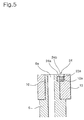
- FIG. 5 is a sectional view illustrating an assembled state of the eccentric coupling device shown in FIG. 4.
- the engagement jaw 24a is horizontally protruded from the upper end of the cut surface 10a.
- the engagement jaw 24a is in contact with the upper end of the stopper 23a at the lower surface thereof.
- the engagement jaw 24a is provided with the stopper insertion allowing groove 24b, which extends vertically.
- the stopper insertion allowing groove 24b is selectively aligned with the stopper hole 12a, so that it allows the stopper 23a to be inserted into the stopper hole 12a.
- the engagement jaw 24a is in contact with the upper end of the stopper 23a fitted in the stopper hole 12a, so that it is engaged with the stopper 23a, thereby preventing a vertical movement of the stopper 23a.
- the stopper 23a is prevented from moving vertically, by the engagement jaw 24a, it is possible to simply prevent the eccentric bush 12 from moving vertically with respect to the crank pin 10.
- the eccentric bush 12 Since the eccentric bush 12 is prevented from moving vertically, by the engagement jaw 24a, it is possible to prevent a tilting phenomenon of the eccentric bush 12 caused by abnormal behavior or axial elevation thereof.
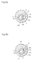
- FIGS. 6a and 6b are cross-sectional views respectively illustrating assembled and operating states of the eccentric coupling device shown in FIG. 4.
- FIG. 6a shows an assembled state of the eccentric coupling device
- FIG. 6b shows an operating state of the eccentric coupling device.
- the stopper 23a is first inserted into the stopper hole 12a of the eccentric bush 12 in a state in which the stopper insertion allowing groove 24b formed at the engagement jaw 24a is aligned with the stopper hole 12a, as shown in FIG. 6a.
- the stopper insertion allowing groove 24b is misaligned from the stopper hole 12a, so that the stopper 23a comes into contact with the lower surface of the engagement jaw 24a at the upper end thereof. Accordingly, the engagement jaw 24a prevents an elevation of the stopper 23a, thereby preventing an axial elevation of the eccentric bush 12 coupled with the stopper 23a.
- the stopper insertion allowing groove 24a provided at the engagement jaw 24a allows the stopper 23a to be easily fitted in the stopper hole 12a in the process of assembling the scroll compressor, while preventing the fitted stopper 23a from being separated from the stopper hole 12a during the operation of the scroll compressor.
- the vertical movement preventing device 24 has been described as comprising the engagement jaw 24a, it is not limited thereto.
- the vertical movement preventing device 24 may be implemented using other structures, as far as they can allow assembly of the stopper 23a while preventing a vertical movement of the stopper 23a during forward and backward rotations of the eccentric bush 12.
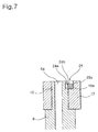
- FIG. 7 is a sectional view illustrating an eccentric coupling device according to another embodiment of the present invention.
- the eccentric coupling device may be applied to the radial compliance scroll compressor shown in FIG. 1.
- the eccentric coupling device will be described in conjunction with the case in which it is applied to the radial compliance scroll compressor shown in FIG. 1.
- elements respectively corresponding to those in FIGS. 4 to 6b will be designated by the same reference numerals.
- an eccentric bush 12 is provided with a crank pin hole 12b so that it is rotatably fitted around a crank pin 10 of a crankshaft 6 through the crank pin hole 12b.
- the crank pin 10 is provided, at one side thereof, with a cutout formed at an upper portion of the crank pin 10 while having a D-shaped cross-section, and thus, a cut surface 10a.
- a stopper hole 12a is also provided at the eccentric bush 12 to extend vertically into the eccentric bush 12. The stopper hole 12a is arranged such that it overlaps with the crank pin hole 12b, while facing the cut surface 10a.
- a stopper 23a is fitted in the stopper hole 12a.
- the stopper 23a has a length shorter than that of the stopper hole 12a.
- an engagement jaw 24a is attached to an upper end of the cut surface 10a to extend horizontally from the cut surface 10a such that it comes into contact with an upper end of the stopper 23a, so that it is engaged with the stopper 23a. In accordance with this engagement, the engagement jaw 24a prevents a vertical movement of the stopper 23a, and thus, a vertical movement of the eccentric bush 12 fitted in the crank pin 10.
- the engagement jaw 24a is detachably attached to the upper end of the cut surface 10a, it is possible to simply achieve replacement of the engagement jaw 24a, while reliably preventing a vertical movement of the stopper 23a, and thus, the eccentric bush 12, using a simple structure.
- the engagement jaw 24a is provided with a stopper insertion allowing groove 24b at a peripheral surface thereof.
- the stopper insertion allowing groove 24b is arranged such that it is aligned with the stopper hole 12a when the stopper hole 12a has been shifted, in accordance with rotation of the eccentric bush 12, from a normal position thereof approximate to the center of the crankshaft 6 to a position thereof spaced away from the center of the crankshaft 6.
- the stopper hole 12a is maintained at the normal position thereof.
- the stopper insertion allowing groove 24b When the stopper insertion allowing groove 24b is aligned with the stopper hole 12a, it allows the stopper 23a to be inserted into the stopper hole 12a without being obstructed by the crank pin 10 including the engagement jaw 24a.
- the stopper insertion allowing groove 24b has an arc shape having a radius of curvature larger than the diameter of the stopper 23a.
- FIG. 8 is an exploded perspective view illustrating an eccentric coupling device according to another embodiment of the present invention.
- the eccentric coupling device may be applied to the radial compliance scroll compressor shown in FIG. 1.
- the eccentric coupling device will be described in conjunction with the case in which it is applied to the radial compliance scroll compressor shown in FIG. 1.
- elements respectively corresponding to those in FIGS. 4 to 6b will be designated by the same reference numerals.
- the eccentric coupling device includes a crank pin 10 provided at an upper end of a crankshaft 6 such that it is eccentrically arranged with respect to the crankshaft 6, an eccentric bush 12 rotatably fitted around the crank pin 10 such that an upper end thereof is arranged at a level higher than that of the crank pin 10, a stopper 23a fitted in the eccentric bush 12 such that an upper end thereof is flush with that of the crank pin 10, and a vertical movement preventing device 24 adapted to prevent a vertical movement of the eccentric bush 12.
- the eccentric bush 12 which is fitted around the crank pin 10, has a length longer than that of the crank pin 10 so that the upper end thereof is arranged at a level higher than that of the crank pin 10.
- the eccentric bush 12 is provided with a crank pin hole 12b extending vertically throughout the eccentric bush 12, and a stopper hole 12a extending vertically into the eccentric bush 12.
- the crank pin hole 12b receives the crank pin 10 such that the crank pin 10 is rotatable therein.
- the crank pin 10 is provided, at one side thereof, with a cutout formed at an upper portion of the crank pin 10 while having a D-shaped cross-section, and thus, a cut surface 10a.
- the stopper 23a is fitted in the stopper hole 12a.
- the stopper hole 12a is arranged such that it overlaps with the crank pin hole 12b, so that the cylindrical stopper 23a fitted in the stopper hole 12a is radially protruded into the crank pin hole 12b.
- the stopper 23a can come into contact with the cut surface 10a in accordance with rotation of the crank pin 10. Accordingly, rotation of the eccentric bush 12 is limited to a certain range.
- the stopper 23a has a length shorter than that of the stopper hole 12a such that the upper end thereof is flush with that of the crank pin 10 in a state of being fitted in the stopper hole 12a.
- the stopper 23a may have a reduced length such that the upper end thereof is arranged at a level slightly lower than that of the crank pin 10.
- the vertical movement preventing device 24 comprises an engagement disc 24a attached to the upper end of the crank pin 10 such that it is arranged over the stopper 23a in a state in which the eccentric bush 12 is fitted around the crank pin 10, and the stopper 23a is fitted in the eccentric bush 12.
- the engagement disc 24a has an outer diameter equal to or smaller than the diameter of the crank pin 10 while having a thickness determined such that an upper surface thereof is flush with the upper end of the eccentric bush 12.
- the engagement disc 24a is provided with a communication hole 24c communicating with an oil passage 6a formed through the crank shaft 6.
- the engagement disc 24a Since the engagement disc 24a is attached to the upper end of the crank pin 10, it prevents a vertical movement of the stopper 23a, and thus, a vertical movement of the eccentric bush 12. In order to allow the stopper 23a to be vertically inserted into the stopper hole 12a in the assembly process, the engagement disc 24a is provided with a stopper insertion allowing groove 24b at a peripheral portion thereof.
- the stopper insertion allowing groove 24b is arranged such that it is aligned with the stopper hole 12a when the stopper hole 12a has been shifted, in accordance with rotation of the eccentric bush 12, from a normal position thereof approximate to the center of the crankshaft 6 to a position thereof spaced away from the center of the crankshaft 6. During a normal operation of the scroll compressor, the stopper hole 12a is maintained at the normal position thereof.
- the stopper insertion allowing groove 24b When the stopper insertion allowing groove 24b is aligned with the stopper hole 12a, it allows the stopper 23a to be inserted into the stopper hole 12a without being obstructed by the crank pin 10 including the engagement disc 24a.
- the stopper insertion allowing groove 24b has an arc shape having a radius of curvature larger than the diameter of the stopper 23a.
- the engagement disc 24a attached to the upper end of the crank pin 10 is used as the vertical movement preventing device 24 adapted to prevent a vertical movement of the eccentric bush 12, it is possible to simply implement the vertical movement preventing device 24, and thus, to simply manufacture the scroll compressor according to the present invention.
- FIG. 9 is a sectional view illustrating an assembled state of the eccentric coupling device shown in FIG. 8.
- the upper end of the crank pin 10 is arranged at a level lower than that of the eccentric bush 12.
- the engagement disc 24a is attached which has a thickness equal to a vertical distance between the upper ends of the crank pin 10 and eccentric bush 12.
- the engagement disc 24a covers a part of the upper end of the stopper 23a protruded into the cutout of the crank pin 10 through the crank pin hole 12b. That is, the engagement disc 24a is engaged with the upper end of the stopper 23a. Accordingly, a vertical movement of the stopper 23a is prevented.
- the attachment of the engagement disc 24a to the crank pin 10 may be achieved, using various methods, for example, a welding process.
- the vertical movement preventing device 24 may be simply and conveniently implemented by coupling the crank pin 10 and eccentric bush 12 such that the upper ends thereof have a level difference, and attaching, to the upper end of the crank pin 10, the engagement disc 24a having a thickness equal to the level difference.
- the engagement disc 24a is provided, at a peripheral portion thereof, with the stopper insertion allowing groove 24b, while being provided, at a central portion thereof, with the communication hole 24c communicating with the oil passage 6a extending through the crankshaft 6 and crank pin 10.
- the reliability of the eccentric bush can be secured because it is possible to prevent an axial elevation of the eccentric bush including the stopper at either the rotated position of the eccentric bush or the normal position of the eccentric bush.
Landscapes
- Engineering & Computer Science (AREA)
- Mechanical Engineering (AREA)
- General Engineering & Computer Science (AREA)
- Rotary Pumps (AREA)
- Applications Or Details Of Rotary Compressors (AREA)
Abstract
An eccentric coupling device in a radial compliance
scroll compressor including a crank pin (10) eccentrically arranged
at an upper end of a crankshaft included in the scroll
compressor, and provided with a vertically-extending cut
surface (10a) at one side thereof, a bush (12) fitted around the crank
pin, and provided with a crank pin hole (12b) and a stopper hole (12a), a
stopper (23) fitted in the stopper hole, and an engagement jaw (24)
adapted to prevent a vertical movement of the stopper, thereby
preventing a vertical movement of the bush, the engagement jaw
being provided at an upper end of the crank pin. The bush is
arranged such that an upper end thereof is flush with an upper
end of the crank pin. The stopper hole overlaps with the crank
pin hole so that the stopper selectively comes into contact
with the cut surface in accordance with a rotation of the crank
pin. The stopper has a length shorter than that of the stopper
hole.
Description
- The present invention relates to a scroll compressor, and more particularly to an eccentric coupling device in a radial compliance scroll compressor, which is capable of preventing abnormal behavior of an eccentric bush caused by a pressure difference between upper and lower ends of the eccentric bush during operation of the scroll compressor, while preventing the eccentric bush from rising axially.
- Generally, a scroll compressor includes upper and lower scrolls respectively provided with involute-shaped wraps engaged with each other. One of the scrolls performs an orbiting motion with respect to the other scroll to reduce the volume of spaces defined between the scrolls, thereby compressing gas confined in the spaces.
- As such a conventional compressor, a radial compliance scroll compressor is known. In such a radial compliance scroll compressor, an orbiting scroll thereof is backwardly moved when liquid refrigerant, oil or foreign matter is introduced into compression chambers defined between the orbiting scroll and the other scroll, that is, a fixed scroll, thereby abnormally increasing the gas pressure in the compression chambers. In accordance with the backward movement of the orbiting scroll, it is possible to prevent the wraps of the scrolls from being damaged due to the abnormally increased gas pressure.
- FIG. 1 is a sectional view illustrating the entire configuration of a conventional radial compliance scroll compressor.
- As shown in FIG. 1, the conventional radial compliance scroll compressor includes a shell 1, and main and
sub frames stator 4, which has a hollow structure, is interposed between the main andsub frames - A
rotor 5 is arranged inside thestator 4 such that it rotates when current flows through thestator 4. Avertical crankshaft 6 extends axially through a central portion of therotor 5 while being fixed to therotor 5 so that it is rotated along with therotor 5. Thecrankshaft 6 has upper and lower ends protruded beyond therotor 5, and rotatably fitted in the main andsub frames crankshaft 6 is rotatably supported by the main andsub frames - An orbiting scroll 7 is mounted to an upper surface of the
main frame 2 in the shell 1. The orbiting scroll 7 is coupled, at a lower portion thereof, with the upper end of thecrankshaft 6, which is protruded through themain frame 2, so that it performs an orbiting motion in accordance with rotation of thecrankshaft 6. The orbiting scroll 7 is provided, at an upper portion thereof, with anorbiting wrap 7a having an involute shape. The orbitingwrap 7a extends upwardly from an upper surface of the orbiting scroll 7. Afixed scroll 8 is arranged on the orbiting scroll 7 in the shell 1 while being fixed to the shell 1. Thefixed scroll 8 is provided, at a lower portion thereof, with afixed wrap 8a adapted to be engaged with the orbitingwrap 7a of the orbiting scroll 7 such thatcompression chambers 22 are defined between thewraps crankshaft 6, gaseous refrigerant is introduced into thecompression chambers 22 in a sequential fashion, so that it is compressed. - For the orbiting motion thereof, the orbiting scroll 7 is eccentrically coupled to the
crankshaft 6. For achieving this eccentric coupling, thecrankshaft 6 is provided with acrank pin 10 upwardly protruded from the upper end of thecrankshaft 6 at a position radially spaced apart from the center of the upper end of thecrankshaft 6 by a certain distance. Also, the orbiting scroll 7 is provided, at the lower portion thereof, with aboss 7b centrally protruded from a lower surface of the orbiting scroll 7. - A
bearing 11 is forcibly fitted in theboss 7b. Also, aneccentric bush 12 is rotatably fitted around thecrank pin 10. Thecrank pin 10 of thecrankshaft 6 is rotatably received in theboss 7b of the orbiting scroll 7 via thebearing 11 andeccentric bush 12, so that the orbiting scroll 7 is eccentrically coupled to thecrankshaft 6. - As a rotation preventing mechanism for the orbiting scroll 7, an Oldham ring 9 is arranged between the
main frame 2 and the orbiting scroll 7. Anoil passage 6a extends vertically throughout thecrankshaft 6. Upper and lowerbalance weight members rotor 5, respectively, in order to prevent a rotation unbalance of thecrankshaft 6 caused by thecrank pin 10. - In FIG. 1,
reference numerals reference numerals reference numeral 19 designates a check valve,reference numeral 20 designates oil, andreference numeral 21 designates an oil propeller. - When current flows through the
stator 4, therotor 5 is rotated inside thestator 4, thereby causing thecrankshaft 6 to rotate. In accordance with the rotation of thecrankshaft 6, the orbiting scroll 7 coupled to thecrank pin 10 of thecrankshaft 6 performs an orbiting motion with an orbiting radius defined between the center of thecrankshaft 6 and the center of the orbiting scroll 7. - In accordance with a continued orbiting motion of the orbiting scroll 7, the
compression chambers 22, which are defined between the orbitingwrap 7a and thefixed wrap 8a, are gradually reduced in volume, so that gaseous refrigerant sucked into eachcompression chamber 22 via thesuction pipe 15 is compressed to high pressure. The compressed high-pressure gaseous refrigerant is subsequently discharged into thedischarge chamber 18 via thedischarge port 17. The compressed high-pressure gaseous refrigerant is then outwardly discharged from thedischarge chamber 18 via thedischarge pipe 16. - Meanwhile, when an abnormal increase in pressure occurs in the
compression chambers 22 due to introduction of liquid refrigerant, oil or foreign matter into thecompression chambers 22, the orbiting scroll 7 is radially shifted such that the orbitingwrap 7a is moved away from thefixed wrap 8a, due to the abnormally increased pressure. As a result, it is possible to prevent thewraps - In the radial compliance scroll compressor having the above mentioned configuration, the
eccentric bush 12 is coupled to thecrank pin 10 in the above mentioned manner, in order to vary the orbiting radius of the orbiting scroll 7. Also, theeccentric bush 12 generates a centrifugal force corresponding to an eccentricity thereof, that is, the distance between the center of thecrank pin 10 and the center of theeccentric bush 12, during the orbiting motion of the orbiting scroll 7. By virtue of this centrifugal force, theeccentric bush 12 can perform a sealing function for thecompression chambers 22. - FIG. 2 is an exploded perspective view illustrating a structure of the conventional eccentric bush.
- As shown in FIG. 2, the
eccentric bush 12 has acrank pin hole 12b so that it is rotatably fitted around thecrank pin 10. When an abnormal increase in pressure occurs in thecompression chambers 22, theeccentric bush 12 is rotated such that the orbiting scroll 7 is radially shifted to cause the orbitingwrap 7a to be moved away from thefixed wrap 8a. - In order to limit the rotation of the
eccentric bush 12 to a predetermined angle, thecrank pin 10 has a cutout having a D-shaped cross-section, and thus, acut surface 10a, at one side thereof. Theeccentric bush 12 also has astopper hole 12a at one side of thecrank pin hole 12b. Acylindrical stopper 23 is fitted in thestopper hole 12a. Thestopper hole 12a is arranged such that it overlaps with thecrank pin hole 12b, so that thecylindrical stopper 23 fitted in thestopper hole 12a is radially protruded into thecrank pin hole 12b. - FIGS. 3a and 3b are cross-sectional views respectively illustrating different operation states of the eccentric bush shown in FIG. 2.
- At a normal position of the
eccentric bush 12, thestopper 23 is spaced apart from thecut surface 10a, as shown in FIG. 3a. - When the
eccentric bush 12 is rotated, as indicated by an arrow in FIG. 3b, thestopper 23 is rotated, along with theeccentric bush 12, so that it comes into contact with thecut surface 10a. Thus, the rotation of theeccentric bush 12 is limited to a certain range. - Meanwhile, oil is fed to the upper end of the
eccentric bush 12 through theoil passage 6a of thecrankshaft 6, and then dispersed from the upper end of theeccentric bush 12 to perform a function of lubricating contact portions of thebearing 11 andeccentric bush 12. However, there may be a difference between the amounts of oil respectively supplied to the upper and lower portions of theeccentric bush 12. - Such an oil supply amount difference may generate friction between the
bearing 11 and theeccentric bush 12 at the lower portion of theeccentric bush 12. Such friction may cause theeccentric bush 12 to rise axially. - The
eccentric bush 12 has an inner peripheral surface roughly machined as compared to an outer peripheral surface thereof to be in slidable contact with thebearing 11. Due to the roughness of the inner peripheral surface of theeccentric bush 12, increased friction is generated between theeccentric bush 12 and thecrank pin 10. For this reason, theeccentric bush 12 exhibits abnormal behavior. For example, theeccentric bush 12 may be repeatedly moved in upward and downward directions without being maintained at a fixed vertical position as it is repeatedly rotated in forward and backward directions during operation of the scroll compressor. Due to such abnormal behavior, theeccentric bush 12 may be axially elevated. - When the
eccentric bush 12 is axially elevated due to various causes including a self-moment thereof, the contact area between theeccentric bush 12 and thecrank pin 10 is reduced by the elevation length of theeccentric bush 12. - For this reason, a tilting phenomenon may occur. That is, the
eccentric bush 12 may be upwardly moved in a state of being inclined to one side thereof. Such a tilting phenomenon causes an increase in the frictional force generated between theeccentric bush 12 and thebearing 11. As a result, the mechanism of the scroll compressor may be damaged. Furthermore, the performance of the scroll compressor may be degraded. - The present invention has been made in view of the above mentioned problems, and an object of the invention is to provide an eccentric coupling device in a radial compliance scroll compressor, which is capable of preventing a pressure difference from being generated between upper and lower ends of an eccentric bush due to a difference between the amounts of oil, respectively supplied to the upper and lower portions of the
eccentric bush 12, caused by dispersion of oil at the upper end of the eccentric bush, while preventing the eccentric bush from rising axially when it repeats forward and backward movements thereof during the compression operation of the scroll compressor. - Another object of the invention is to provide an eccentric coupling device in a scroll compressor which has a simple construction while being capable of achieving the above object.
- Another object of the invention is to provide an eccentric coupling device in a scroll compressor which is capable of preventing an eccentric bush carrying a stopper from rising axially at either a normal position or a rotated position.
- In accordance with an aspect, the present invention provides an eccentric coupling device in a radial compliance scroll compressor comprising: a crank pin eccentrically arranged at an upper end of a crankshaft included in the scroll compressor, and provided with a vertically-extending cut surface at one side thereof; a bush provided with a crank pin hole adapted to receive the crank pin, and a stopper hole provided at the eccentric bush at one side of the crank pin hole such that the stopper hole overlaps with the crank pin hole; a stopper fitted in the stopper hole such that the stopper is radially protruded into the crank pin hole toward the cut surface to selectively come into contact with the cut surface in accordance with a rotation of the bush; and a vertical movement preventing device adapted to prevent a vertical movement of the stopper, thereby preventing a vertical movement of the eccentric bush, the vertical movement preventing device being provided at an upper end of the crank pin.
- The vertical movement preventing device prevents abnormal behavior of the eccentric bush caused by a pressure difference between upper and lower ends of the eccentric bush, and an axial elevation of the eccentric bush occurring during rotation of the eccentric bush.
- The vertical movement preventing device may comprise an engagement jaw horizontally protruded from an upper end of the cut surface such that the engagement jaw is engagable with a part of the stopper fitted in the stopper hole. The engagement jaw may be integral with the crank pin. In this case, it is possible to simply form the engagement jaw, and to prevent a vertical movement of the stopper with the simple structure.
- The engagement jaw may be detachably attached to the cut surface. In the event the engagement jaw is detachable from the crank pin, it is possible to simply achieve replacement of the engagement jaw, while reliably preventing a vertical movement of the stopper with the simple structure.
- The engagement jaw may be provided with a stopper insertion allowing groove formed to extend vertically, and adapted to allow the stopper to be vertically inserted into the stopper hole. By virtue of the stopper insertion allowing groove, the stopper can be simply fitted in the stopper hole without being obstructed by the engagement jaw.
- The stopper insertion allowing groove may be arranged such that it is aligned with the stopper hole when a center of the bush is positioned at a position thereof spaced away from a center of the crankshaft in accordance with a rotation of the bush. In accordance with this arrangement of the stopper insertion allowing groove, the stopper is allowed to be inserted into the stopper hole in the process of assembling the scroll compressor, while being prevented from being separated from the stopper hole via the stopper insertion allowing groove during the normal operation of the scroll compressor.
- The stopper insertion allowing groove may have an arc shape having a radius of curvature larger than a diameter of the stopper. In accordance with this shape of the stopper insertion allowing groove, it is possible to more easily fit the stopper in the stopper hole.
- The vertical movement preventing device may comprise an engagement disc attached to the upper end of the crank pin to be arranged over the crank pin. The engagement disc may have an outer diameter equal to or smaller than a diameter of the crank pin such that the engagement jaw is engagable with a part of the stopper fitted in the stopper hole, while being provided with a communication hole communicating with an oil passage extending throughout the crankshaft. Since the vertical movement preventing device is implemented by the engagement disc, it is possible to prevent a vertical movement of the stopper with a simple structure. The engagement disc may be provided with a stopper insertion allowing groove formed to extend vertically, and adapted to allow the stopper to be vertically inserted into the stopper hole. By virtue of the stopper insertion allowing groove, it is possible to simply fit the stopper in the stopper hole via the engagement disc.
- The above objects, and other features and advantages of the present invention will become more apparent after reading the following detailed description when taken in conjunction with the drawings, in which:
- FIG. 1 is a sectional view illustrating the entire configuration of a conventional radial compliance scroll compressor;
- FIG. 2 is an exploded perspective view illustrating a structure of a conventional eccentric coupling device;
- FIG. 3a is a cross-sectional view illustrating the state in which an eccentric bush of FIG. 2 is positioned at a normal position;
- FIG. 3b is a cross-sectional view illustrating the state in which the eccentric bush of FIG. 2 is positioned at a rotated position;
- FIG. 4 is an exploded perspective view illustrating an eccentric coupling device according to an embodiment of the present invention;
- FIG. 5 is a sectional view illustrating an assembled state of the eccentric coupling device shown in FIG. 4;
- FIG. 6a is a cross-sectional view illustrating the state in which an eccentric bush of FIG. 4 is positioned at a normal position;
- FIG. 6b is a cross-sectional view illustrating the state in which the eccentric bush of FIG. 4 is positioned at a rotated position;
- FIG. 7 is a sectional view illustrating an eccentric coupling device according to another embodiment of the present invention;
- FIG. 8 is an exploded perspective view illustrating an eccentric coupling device according to another embodiment of the present invention; and
- FIG. 9 is a sectional view illustrating an assembled state of the eccentric coupling device shown in FIG. 8.
-
- Now, embodiments of an eccentric coupling device in a radial compliance scroll compressor according to the present invention will be described with reference to the annexed drawings.
- FIG. 4 is an exploded perspective view illustrating an eccentric coupling device according to an embodiment of the present invention. The eccentric coupling device may be applied to the radial compliance scroll compressor shown in FIG. 1. In order to simplify the description thereof, the eccentric coupling device will be described in conjunction with the case in which it is applied to the radial compliance scroll compressor shown in FIG. 1. In FIG. 4, elements respectively corresponding to those in FIGS. 1 and 2 will be designated by the same reference numerals.
- As shown in FIG. 4, the eccentric coupling device includes a
crank pin 10 provided at an upper end of acrankshaft 6 such that it is eccentrically arranged with respect to thecrankshaft 6, aneccentric bush 12 rotatably fitted around thecrank pin 10, astopper 23a fitted in theeccentric bush 12, and a verticalmovement preventing device 24 adapted to prevent a vertical movement of theeccentric bush 12. - The
eccentric bush 12, which is fitted around thecrank pin 10, is flush with thecrank pin 10. Theeccentric bush 12 is provided with acrank pin hole 12b extending vertically throughout theeccentric bush 12, and astopper hole 12a extending vertically into theeccentric bush 12. The crankpin hole 12b receives thecrank pin 10 such that thecrank pin 10 is rotatable therein. Thecrank pin 10 is provided, at one side thereof, with a cutout formed at an upper portion of thecrank pin 10 while having a D-shaped cross-section, and thus, acut surface 10a. - The
stopper 23a is fitted in thestopper hole 12a. Thestopper hole 12a is arranged such that it overlaps with thecrank pin hole 12b, so that thecylindrical stopper 23a fitted in thestopper hole 12a is radially protruded into thecrank pin hole 12b. In accordance with this arrangement, thestopper 23a can come into contact with thecut surface 10a in accordance with rotation of thecrank pin 10. Accordingly, rotation of theeccentric bush 12 is limited to a certain range. - The
stopper 23a has a length shorter than that of thestopper hole 12a. Thestopper 23a may be tightly fitted in thestopper hole 12a so that it is firmly fixed to theeccentric bush 12. Alternatively, thestopper 23a may be formed such that it is integral with theeccentric bush 12. - The vertical
movement preventing device 24 comprises anengagement jaw 24a protruded from thecrank pin 10 at an upper end of thecut surface 10a such that it comes into contact with an upper end of thestopper 23a positioned below an upper end of thestopper hole 12a, so that it is engaged with thestopper 23a. Theengagement jaw 24a is formed such that it is integral with thecrank pin 10. - In accordance with the engagement of the
engagement jaw 24a with thestopper 23a, the verticalmovement preventing device 24 prevents a vertical movement of thestopper 23a, and thus, a vertical movement of theeccentric bush 12 fitted in thecrank pin 10. Accordingly, it is possible to prevent a tilting phenomenon of theeccentric bush 12, thereby eliminating a degradation in the compression efficiency and performance of the scroll compressor caused by the tilting phenomenon. - The
engagement jaw 24a has a D-shaped cross-section complemetary to that of the cutout formed at the upper portion of thecrank pin 10 to form thecut surface 10a. Theengagement jaw 24a is provided with a stopperinsertion allowing groove 24b at a peripheral surface thereof. The stopperinsertion allowing groove 24b is formed by partially cutting out a peripheral portion of theengagement jaw 24a in the form of a C-shaped cutout. - The stopper
insertion allowing groove 24b is arranged such that it is aligned with thestopper hole 12a when thestopper hole 12a has been shifted, in accordance with rotation of theeccentric bush 12, from a normal position thereof approximate to the center of thecrankshaft 6 to a position thereof spaced away from the center of thecrankshaft 6. During a normal operation of the scroll compressor, thestopper hole 12a is maintained at the normal position thereof. When the stopperinsertion allowing groove 24b is aligned with thestopper hole 12a, it allows thestopper 23a to be vertically inserted into thestopper hole 12a without being obstructed by thecrank pin 10 including theengagement jaw 24a. During the normal operation of the scroll compressor, thestopper 23a fitted in thestopper hole 12a is not separated from thestopper hole 12a by theengagement jaw 24a. - The stopper
insertion allowing groove 24b has an arc shape having a radius of curvature larger than the diameter of thestopper 23a. Accordingly, the stopperinsertion allowing groove 24b allows thestopper 23a to be more easily inserted into thestopper hole 12a. - Thus, the stopper
insertion allowing groove 24b has the form of a C-shaped cutout, and serves to allow thestopper 23a to be easily fitted in thestopper hole 12a in the process of assembling the scroll compressor, while preventing the fittedstopper 23a from being separated from thestopper hole 12a. - Preferably, the
stopper 23a has a length shorter than the distance between a lower end of thecut surface 10a and a lower surface of theengagement jaw 24a. Meanwhile, although thestopper 23a has a cylindrical shape in the illustrated case, it is not limited thereto. Provided, the shape of the stopperinsertion allowing groove 24b should be determined in accordance with the shape of thestopper 23a. Also, theengagement jaw 23a should have a thickness determined, taking into consideration a force causing elevation of theeccentric bush 12 andstopper 23a. - The length of the
stopper 23a is determined in accordance with the distance between the lower end of thecut surface 10a and the lower surface of theengagement jaw 24a. In this connection, it is preferred that the length of thestopper 23a is slightly shorter than the distance between the lower end of thecut surface 10a and the lower surface of theengagement jaw 24a, as described above. - Although the
stopper 23a has a length shorter than the distance between the lower end of thecut surface 10a and the lower surface of theengagement jaw 24a, there is no adverse affect on a required function of thestopper 23a. - FIG. 5 is a sectional view illustrating an assembled state of the eccentric coupling device shown in FIG. 4.
- As shown in FIG. 5, the
engagement jaw 24a is horizontally protruded from the upper end of thecut surface 10a. Theengagement jaw 24a is in contact with the upper end of thestopper 23a at the lower surface thereof. - As described above, the
engagement jaw 24a is provided with the stopperinsertion allowing groove 24b, which extends vertically. The stopperinsertion allowing groove 24b is selectively aligned with thestopper hole 12a, so that it allows thestopper 23a to be inserted into thestopper hole 12a. - The
engagement jaw 24a is in contact with the upper end of thestopper 23a fitted in thestopper hole 12a, so that it is engaged with thestopper 23a, thereby preventing a vertical movement of thestopper 23a. As thestopper 23a is prevented from moving vertically, by theengagement jaw 24a, it is possible to simply prevent theeccentric bush 12 from moving vertically with respect to the crankpin 10. - Since the
eccentric bush 12 is prevented from moving vertically, by theengagement jaw 24a, it is possible to prevent a tilting phenomenon of theeccentric bush 12 caused by abnormal behavior or axial elevation thereof. - FIGS. 6a and 6b are cross-sectional views respectively illustrating assembled and operating states of the eccentric coupling device shown in FIG. 4. FIG. 6a shows an assembled state of the eccentric coupling device, whereas FIG. 6b shows an operating state of the eccentric coupling device.
- In the process of assembling the radial compliance scroll compressor, the
stopper 23a is first inserted into thestopper hole 12a of theeccentric bush 12 in a state in which the stopperinsertion allowing groove 24b formed at theengagement jaw 24a is aligned with thestopper hole 12a, as shown in FIG. 6a. - When the scroll compressor is operated in the assembled state shown in FIG. 6a, the
eccentric bush 12 is rotated, as shown in FIG. 6b, because a centrifugal force generated at an initial stage of the operation of the scroll compressor is smaller than a gas pressure in the compression chambers of the scroll compressor. - As a result, the stopper
insertion allowing groove 24b is misaligned from thestopper hole 12a, so that thestopper 23a comes into contact with the lower surface of theengagement jaw 24a at the upper end thereof. Accordingly, theengagement jaw 24a prevents an elevation of thestopper 23a, thereby preventing an axial elevation of theeccentric bush 12 coupled with thestopper 23a. - Even at a normal position of the
eccentric bush 12 where the generated centrifugal force is larger than the gas pressure in the compression chambers in accordance with a continued orbiting motion carried out in the scroll compressor, thestopper 23a is maintained in a state of being engaged with theengagement jaw 24a. Accordingly, theeccentric bush 12 is still prevented from rising axially. - Thus, the stopper
insertion allowing groove 24a provided at theengagement jaw 24a allows thestopper 23a to be easily fitted in thestopper hole 12a in the process of assembling the scroll compressor, while preventing the fittedstopper 23a from being separated from thestopper hole 12a during the operation of the scroll compressor. - Although the vertical
movement preventing device 24 has been described as comprising theengagement jaw 24a, it is not limited thereto. The verticalmovement preventing device 24 may be implemented using other structures, as far as they can allow assembly of thestopper 23a while preventing a vertical movement of thestopper 23a during forward and backward rotations of theeccentric bush 12. - FIG. 7 is a sectional view illustrating an eccentric coupling device according to another embodiment of the present invention. The eccentric coupling device may be applied to the radial compliance scroll compressor shown in FIG. 1. In order to simplify the description thereof, the eccentric coupling device will be described in conjunction with the case in which it is applied to the radial compliance scroll compressor shown in FIG. 1. In FIG. 7, elements respectively corresponding to those in FIGS. 4 to 6b will be designated by the same reference numerals.
- Referring to FIG. 7, an
eccentric bush 12 is provided with acrank pin hole 12b so that it is rotatably fitted around acrank pin 10 of acrankshaft 6 through thecrank pin hole 12b. Thecrank pin 10 is provided, at one side thereof, with a cutout formed at an upper portion of thecrank pin 10 while having a D-shaped cross-section, and thus, acut surface 10a. Astopper hole 12a is also provided at theeccentric bush 12 to extend vertically into theeccentric bush 12. Thestopper hole 12a is arranged such that it overlaps with thecrank pin hole 12b, while facing thecut surface 10a. - A
stopper 23a is fitted in thestopper hole 12a. Thestopper 23a has a length shorter than that of thestopper hole 12a. As a verticalmovement preventing device 24 adapted to prevent a vertical movement of theeccentric bush 12, anengagement jaw 24a is attached to an upper end of thecut surface 10a to extend horizontally from thecut surface 10a such that it comes into contact with an upper end of thestopper 23a, so that it is engaged with thestopper 23a. In accordance with this engagement, theengagement jaw 24a prevents a vertical movement of thestopper 23a, and thus, a vertical movement of theeccentric bush 12 fitted in thecrank pin 10. - Since the
engagement jaw 24a is detachably attached to the upper end of thecut surface 10a, it is possible to simply achieve replacement of theengagement jaw 24a, while reliably preventing a vertical movement of thestopper 23a, and thus, theeccentric bush 12, using a simple structure. - The
engagement jaw 24a is provided with a stopperinsertion allowing groove 24b at a peripheral surface thereof. The stopperinsertion allowing groove 24b is arranged such that it is aligned with thestopper hole 12a when thestopper hole 12a has been shifted, in accordance with rotation of theeccentric bush 12, from a normal position thereof approximate to the center of thecrankshaft 6 to a position thereof spaced away from the center of thecrankshaft 6. During a normal operation of the scroll compressor, thestopper hole 12a is maintained at the normal position thereof. When the stopperinsertion allowing groove 24b is aligned with thestopper hole 12a, it allows thestopper 23a to be inserted into thestopper hole 12a without being obstructed by thecrank pin 10 including theengagement jaw 24a. Preferably, the stopperinsertion allowing groove 24b has an arc shape having a radius of curvature larger than the diameter of thestopper 23a. - FIG. 8 is an exploded perspective view illustrating an eccentric coupling device according to another embodiment of the present invention. The eccentric coupling device may be applied to the radial compliance scroll compressor shown in FIG. 1. In order to simplify the description thereof, the eccentric coupling device will be described in conjunction with the case in which it is applied to the radial compliance scroll compressor shown in FIG. 1. In FIG. 8, elements respectively corresponding to those in FIGS. 4 to 6b will be designated by the same reference numerals.
- As shown in FIG. 8, the eccentric coupling device includes a
crank pin 10 provided at an upper end of acrankshaft 6 such that it is eccentrically arranged with respect to thecrankshaft 6, aneccentric bush 12 rotatably fitted around thecrank pin 10 such that an upper end thereof is arranged at a level higher than that of thecrank pin 10, astopper 23a fitted in theeccentric bush 12 such that an upper end thereof is flush with that of thecrank pin 10, and a verticalmovement preventing device 24 adapted to prevent a vertical movement of theeccentric bush 12. - The
eccentric bush 12, which is fitted around thecrank pin 10, has a length longer than that of thecrank pin 10 so that the upper end thereof is arranged at a level higher than that of thecrank pin 10. Theeccentric bush 12 is provided with acrank pin hole 12b extending vertically throughout theeccentric bush 12, and astopper hole 12a extending vertically into theeccentric bush 12. The crankpin hole 12b receives thecrank pin 10 such that thecrank pin 10 is rotatable therein. Thecrank pin 10 is provided, at one side thereof, with a cutout formed at an upper portion of thecrank pin 10 while having a D-shaped cross-section, and thus, acut surface 10a. - The
stopper 23a is fitted in thestopper hole 12a. Thestopper hole 12a is arranged such that it overlaps with thecrank pin hole 12b, so that thecylindrical stopper 23a fitted in thestopper hole 12a is radially protruded into thecrank pin hole 12b. In accordance with this arrangement, thestopper 23a can come into contact with thecut surface 10a in accordance with rotation of thecrank pin 10. Accordingly, rotation of theeccentric bush 12 is limited to a certain range. - The
stopper 23a has a length shorter than that of thestopper hole 12a such that the upper end thereof is flush with that of thecrank pin 10 in a state of being fitted in thestopper hole 12a. Thestopper 23a may have a reduced length such that the upper end thereof is arranged at a level slightly lower than that of thecrank pin 10. - The vertical
movement preventing device 24 comprises anengagement disc 24a attached to the upper end of thecrank pin 10 such that it is arranged over thestopper 23a in a state in which theeccentric bush 12 is fitted around thecrank pin 10, and thestopper 23a is fitted in theeccentric bush 12. Theengagement disc 24a has an outer diameter equal to or smaller than the diameter of thecrank pin 10 while having a thickness determined such that an upper surface thereof is flush with the upper end of theeccentric bush 12. Theengagement disc 24a is provided with acommunication hole 24c communicating with anoil passage 6a formed through thecrank shaft 6. - Since the
engagement disc 24a is attached to the upper end of thecrank pin 10, it prevents a vertical movement of thestopper 23a, and thus, a vertical movement of theeccentric bush 12. In order to allow thestopper 23a to be vertically inserted into thestopper hole 12a in the assembly process, theengagement disc 24a is provided with a stopperinsertion allowing groove 24b at a peripheral portion thereof. - The stopper
insertion allowing groove 24b is arranged such that it is aligned with thestopper hole 12a when thestopper hole 12a has been shifted, in accordance with rotation of theeccentric bush 12, from a normal position thereof approximate to the center of thecrankshaft 6 to a position thereof spaced away from the center of thecrankshaft 6. During a normal operation of the scroll compressor, thestopper hole 12a is maintained at the normal position thereof. When the stopperinsertion allowing groove 24b is aligned with thestopper hole 12a, it allows thestopper 23a to be inserted into thestopper hole 12a without being obstructed by thecrank pin 10 including theengagement disc 24a. Preferably, the stopperinsertion allowing groove 24b has an arc shape having a radius of curvature larger than the diameter of thestopper 23a. - Since the
engagement disc 24a attached to the upper end of thecrank pin 10 is used as the verticalmovement preventing device 24 adapted to prevent a vertical movement of theeccentric bush 12, it is possible to simply implement the verticalmovement preventing device 24, and thus, to simply manufacture the scroll compressor according to the present invention. - FIG. 9 is a sectional view illustrating an assembled state of the eccentric coupling device shown in FIG. 8.
- In a state in which the
crank pin 10 is fitted in thecrank pin hole 12b of theeccentric bush 12, as shown in FIG. 9, the upper end of thecrank pin 10 is arranged at a level lower than that of theeccentric bush 12. To the upper end of thecrank pin 10, theengagement disc 24a is attached which has a thickness equal to a vertical distance between the upper ends of thecrank pin 10 andeccentric bush 12. - The
engagement disc 24a covers a part of the upper end of thestopper 23a protruded into the cutout of thecrank pin 10 through thecrank pin hole 12b. That is, theengagement disc 24a is engaged with the upper end of thestopper 23a. Accordingly, a vertical movement of thestopper 23a is prevented. The attachment of theengagement disc 24a to the crankpin 10 may be achieved, using various methods, for example, a welding process. - Thus, the vertical
movement preventing device 24 may be simply and conveniently implemented by coupling thecrank pin 10 andeccentric bush 12 such that the upper ends thereof have a level difference, and attaching, to the upper end of thecrank pin 10, theengagement disc 24a having a thickness equal to the level difference. - Also, the
engagement disc 24a is provided, at a peripheral portion thereof, with the stopperinsertion allowing groove 24b, while being provided, at a central portion thereof, with thecommunication hole 24c communicating with theoil passage 6a extending through thecrankshaft 6 and crankpin 10. - As apparent from the above description, in accordance with the present invention, it is possible to prevent a reduction in the contact area between the eccentric bush and the crank pin caused by an axial elevation of the eccentric bush, and thus, a tilting phenomenon of the eccentric bush caused by the contact area reduction. There is also an advantage in that it is possible to eliminate a degradation in the compression efficiency and performance of the scroll compressor caused by increased friction generated between the eccentric bush and the bearing due to the tilting phenomenon.
- Such effects can be obtained, using a simple structure. Accordingly, it is possible to achieve an improvement in workability and a reduction in manufacturing costs.
- In accordance with the present invention, the reliability of the eccentric bush can be secured because it is possible to prevent an axial elevation of the eccentric bush including the stopper at either the rotated position of the eccentric bush or the normal position of the eccentric bush.
- Although the preferred embodiments of the invention have been disclosed for illustrative purposes, those skilled in the art will appreciate that various modifications, additions and substitutions are possible, without departing from the scope and spirit of the invention as disclosed in the accompanying claims.
Claims (11)
- An eccentric coupling device for a radial compliance scroll compressor comprising:a crank pin eccentrically arranged at an upper end of a crankshaft, and provided with a vertically-extending cut surface at one side thereof;a bush provided with a crank pin hole adapted to receive the crank pin, and a stopper hole provided at the bush at one side of the crank pin hole such that the stopper hole overlaps with the crank pin hole; anda stopper fitted in the stopper hole such that the stopper is radially protruded into the crank pin hole toward the cut surface to selectively come into contact with the cut surface in accordance with a rotation of the bush ; characterised in that the eccentric coupling device further comprisesa vertical movement preventing device adapted to prevent a vertical movement of the stopper, thereby preventing a vertical movement of the bush, the vertical movement preventing device being provided at an upper end of the crank pin.
- The eccentric coupling device according to claim 1, wherein the vertical movement preventing device comprises:an engagement jaw horizontally protruded from an upper end of the cut surface such that the engagement jaw is engagable with a part of the stopper fitted in the stopper hole.
- The eccentric coupling device according to claim 2, wherein the engagement jaw is detachably attached to the cut surface.
- The eccentric coupling device according to claims 2 or 3, wherein the engagement jaw is provided with a stopper insertion allowing groove formed to extend vertically, and adapted to allow the stopper to be vertically inserted into the stopper hole.
- The eccentric coupling device according to claim 4, wherein the stopper insertion allowing groove is arranged such that it is aligned with the stopper hole when a center of the bush is positioned at a position thereof spaced away from a center of the crankshaft in accordance with a rotation of the bush.
- The eccentric coupling device according to claims 4 r 5, wherein the stopper insertion allowing groove has an arc shape having a radius of curvature larger than a diameter of the stopper.
- The eccentric coupling device according to claim 1, wherein the vertical movement preventing device comprises:an engagement disc attached to the upper end of the crank pin, which engagement disc provides an engagement jaw which is engagable with a part of the stopper fitted in the stopper hole and is provided with a communication hole communicating with an oil passage extending throughout the crankshaft.
- The eccentric coupling device according to claim 7, characterized in that the engagement disc having an outer diameter equal to or smaller than a diameter of the crank pin.
- The eccentric coupling device according to claims 7 or 8, wherein the engagement disc is provided with a stopper insertion allowing groove which is adapted to allow the stopper to be vertically inserted into the stopper hole.
- The eccentric coupling device according to claim 8, wherein the stopper insertion allowing groove is arranged such that it is aligned with the stopper hole when a center of the bush is positioned at a position thereof spaced away from a center of the crankshaft in accordance with a rotation of the bush, .
- The eccentric coupling device according to claims 8, 9 or 10, wherein the stopper insertion allowing groove has an arc shape having a radius of curvature larger than a diameter of the stopper.
Applications Claiming Priority (2)
| Application Number | Priority Date | Filing Date | Title |
|---|---|---|---|
| KR1020030091939A KR100558813B1 (en) | 2003-12-16 | 2003-12-16 | Eccentric Bushing Prevention Device of Scroll Compressor |
| KR2003091939 | 2003-12-16 |
Publications (1)
| Publication Number | Publication Date |
|---|---|
| EP1544471A1 true EP1544471A1 (en) | 2005-06-22 |
Family
ID=34511232
Family Applications (1)
| Application Number | Title | Priority Date | Filing Date |
|---|---|---|---|
| EP04077230A Withdrawn EP1544471A1 (en) | 2003-12-16 | 2004-08-04 | Eccentric coupling device in radial compliance scroll compressor |
Country Status (4)
| Country | Link |
|---|---|
| US (1) | US7150609B2 (en) |
| EP (1) | EP1544471A1 (en) |
| KR (1) | KR100558813B1 (en) |
| CN (1) | CN100371604C (en) |
Families Citing this family (21)
| Publication number | Priority date | Publication date | Assignee | Title |
|---|---|---|---|---|
| KR100811655B1 (en) * | 2005-09-28 | 2008-03-11 | 삼성전자주식회사 | Capacity variable rotary compressor |
| KR101849138B1 (en) * | 2012-01-04 | 2018-04-16 | 엘지전자 주식회사 | Scroll compressor with shaft inserting portion and manufacturing method thereof |
| US9920762B2 (en) * | 2012-03-23 | 2018-03-20 | Bitzer Kuehlmaschinenbau Gmbh | Scroll compressor with tilting slider block |
| CN105003526B (en) * | 2015-07-02 | 2019-04-05 | 广东美芝制冷设备有限公司 | Rotary compressor and its crankshaft |
| WO2017114546A1 (en) * | 2015-12-28 | 2017-07-06 | Volvo Construction Equipment Ab | Eccentric assembly for a vibration compacting machine |
| CN208564964U (en) * | 2016-01-14 | 2019-03-01 | 三菱电机株式会社 | scroll compressor |
| US10590834B2 (en) | 2017-03-30 | 2020-03-17 | Quest Engines, LLC | Internal combustion engine |
| US10465629B2 (en) | 2017-03-30 | 2019-11-05 | Quest Engines, LLC | Internal combustion engine having piston with deflector channels and complementary cylinder head |
| US10989138B2 (en) | 2017-03-30 | 2021-04-27 | Quest Engines, LLC | Internal combustion engine |
| US10526953B2 (en) | 2017-03-30 | 2020-01-07 | Quest Engines, LLC | Internal combustion engine |
| US10590813B2 (en) | 2017-03-30 | 2020-03-17 | Quest Engines, LLC | Internal combustion engine |
| US10753308B2 (en) | 2017-03-30 | 2020-08-25 | Quest Engines, LLC | Internal combustion engine |
| US11041456B2 (en) | 2017-03-30 | 2021-06-22 | Quest Engines, LLC | Internal combustion engine |
| US10598285B2 (en) | 2017-03-30 | 2020-03-24 | Quest Engines, LLC | Piston sealing system |
| JP6894981B2 (en) | 2017-04-28 | 2021-06-30 | クエスト エンジンズ,エルエルシー | Variable volume chamber device |
| WO2018204684A1 (en) | 2017-05-04 | 2018-11-08 | Quest Engines, LLC | Variable volume chamber for interaction with a fluid |
| US10753359B2 (en) | 2017-07-31 | 2020-08-25 | Trane International Inc. | Scroll compressor shaft |
| US11060636B2 (en) | 2017-09-29 | 2021-07-13 | Quest Engines, LLC | Engines and pumps with motionless one-way valve |
| WO2019147797A2 (en) | 2018-01-26 | 2019-08-01 | Quest Engines, LLC | Audio source waveguide |
| US10753267B2 (en) | 2018-01-26 | 2020-08-25 | Quest Engines, LLC | Method and apparatus for producing stratified streams |
| CN113482923B (en) * | 2021-08-27 | 2022-09-09 | 广东美的环境科技有限公司 | Compression assembly, scroll compressor and air conditioner |
Citations (4)
| Publication number | Priority date | Publication date | Assignee | Title |
|---|---|---|---|---|
| US5458472A (en) * | 1992-10-28 | 1995-10-17 | Kabushiki Kaisha Toyoda Jidoshokki Seisakusho | Scroll type compressor having thrust regulation on the eccentric shaft |
| JPH10220369A (en) * | 1997-02-05 | 1998-08-18 | Mitsubishi Electric Corp | Scroll compressor |
| JP2000073970A (en) * | 1998-08-27 | 2000-03-07 | Fujitsu General Ltd | Scroll compressor |
| US20020001532A1 (en) * | 2000-06-30 | 2002-01-03 | Chang Yong Il | Radial compliance scroll compressor |
Family Cites Families (18)
| Publication number | Priority date | Publication date | Assignee | Title |
|---|---|---|---|---|
| JPS5867903A (en) | 1981-10-20 | 1983-04-22 | Sanden Corp | Volume type fluid device enabling unloading at the time of starting |
| JPS62162786A (en) | 1986-01-10 | 1987-07-18 | Sanyo Electric Co Ltd | Scroll compressor |
| US5199862A (en) | 1990-07-24 | 1993-04-06 | Mitsubishi Jukogyo Kabushiki Kaisha | Scroll type fluid machinery with counter weight on drive bushing |
| JPH04175486A (en) | 1990-07-24 | 1992-06-23 | Mitsubishi Heavy Ind Ltd | Scroll type fluid machine |
| US5104302A (en) * | 1991-02-04 | 1992-04-14 | Tecumseh Products Company | Scroll compressor including drive pin and roller assembly having sliding wedge member |
| JP3106737B2 (en) * | 1992-11-17 | 2000-11-06 | 株式会社豊田自動織機製作所 | Scroll compressor |
| US5378129A (en) * | 1993-12-06 | 1995-01-03 | Copeland Corporation | Elastic unloader for scroll machines |
| JP2868998B2 (en) | 1994-03-14 | 1999-03-10 | 株式会社デンソー | Scroll compressor |
| DE69504233T2 (en) * | 1994-03-15 | 1999-01-07 | Denso Corp., Kariya, Aichi | Scroll compressor |
| JPH0893665A (en) * | 1994-09-20 | 1996-04-09 | Sanden Corp | Scroll compressor |
| JP3314562B2 (en) | 1994-11-30 | 2002-08-12 | 松下電器産業株式会社 | Scroll compressor |
| US5496158A (en) * | 1994-12-22 | 1996-03-05 | Carrier Corporation | Drive for scroll compressor |
| EP0921316A1 (en) * | 1997-12-03 | 1999-06-09 | Sanden Corporation | Scroll compressor with radial guiding pin in eccentric bush |
| JPH11280674A (en) * | 1998-03-31 | 1999-10-15 | Fujitsu General Ltd | Scroll compressor |
| JP2001234877A (en) * | 2000-02-22 | 2001-08-31 | Mitsubishi Heavy Ind Ltd | Scroll compressor and noise preventing method |
| JP2001342977A (en) * | 2000-06-01 | 2001-12-14 | Keihin Corp | Scroll compressor |
| KR100400573B1 (en) * | 2001-08-22 | 2003-10-08 | 엘지전자 주식회사 | Variable amount control apparatus for scroll compressor |
| JP3858762B2 (en) | 2002-05-29 | 2006-12-20 | ダイキン工業株式会社 | Slide bush and scroll type fluid machine |
-
2003
- 2003-12-16 KR KR1020030091939A patent/KR100558813B1/en not_active Expired - Fee Related
-
2004
- 2004-06-22 US US10/872,373 patent/US7150609B2/en not_active Expired - Fee Related
- 2004-07-14 CN CNB2004100638752A patent/CN100371604C/en not_active Expired - Fee Related
- 2004-08-04 EP EP04077230A patent/EP1544471A1/en not_active Withdrawn
Patent Citations (4)
| Publication number | Priority date | Publication date | Assignee | Title |
|---|---|---|---|---|
| US5458472A (en) * | 1992-10-28 | 1995-10-17 | Kabushiki Kaisha Toyoda Jidoshokki Seisakusho | Scroll type compressor having thrust regulation on the eccentric shaft |
| JPH10220369A (en) * | 1997-02-05 | 1998-08-18 | Mitsubishi Electric Corp | Scroll compressor |
| JP2000073970A (en) * | 1998-08-27 | 2000-03-07 | Fujitsu General Ltd | Scroll compressor |
| US20020001532A1 (en) * | 2000-06-30 | 2002-01-03 | Chang Yong Il | Radial compliance scroll compressor |
Non-Patent Citations (2)
| Title |
|---|
| PATENT ABSTRACTS OF JAPAN vol. 1998, no. 13 30 November 1998 (1998-11-30) * |
| PATENT ABSTRACTS OF JAPAN vol. 2000, no. 06 22 September 2000 (2000-09-22) * |
Also Published As
| Publication number | Publication date |
|---|---|
| KR100558813B1 (en) | 2006-03-10 |
| US20050129552A1 (en) | 2005-06-16 |
| CN1629487A (en) | 2005-06-22 |
| CN100371604C (en) | 2008-02-27 |
| KR20050060338A (en) | 2005-06-22 |
| US7150609B2 (en) | 2006-12-19 |
Similar Documents
| Publication | Publication Date | Title |
|---|---|---|
| US7150609B2 (en) | Eccentric coupling device in radial compliance scroll compressor | |
| KR100916554B1 (en) | Scroll compressor having a clearance for the oldham coupling | |
| AU2010214779A1 (en) | Scroll fluid machine | |
| EP1544469B1 (en) | Eccentric coupling device in radial compliance scroll compressor. | |
| EP1544468B1 (en) | Scroll compressor eccentric bush structure | |
| EP1544470B1 (en) | Scroll compressor eccentric coupling device | |
| KR20130031736A (en) | Scroll compressor | |
| US20130078129A1 (en) | Scroll compressor | |
| EP3567212B1 (en) | Compressor having oldham's ring | |
| JP4578052B2 (en) | Scroll compressor | |
| JP7523370B2 (en) | Scroll Compressor | |
| KR100672283B1 (en) | Scroll compressors with anti-rotation mechanism | |
| JP3951349B2 (en) | Scroll compressor | |
| KR100741684B1 (en) | Scroll compressors with anti-rotation mechanism | |
| JP5078856B2 (en) | Compressor | |
| JP2003301784A (en) | Rotation preventing mechanism of scroll fluid machine | |
| JP3574904B2 (en) | Closed displacement compressor | |
| JP4127110B2 (en) | Scroll compressor | |
| US8939741B2 (en) | Scroll compressor | |
| KR100608868B1 (en) | Assembly structure of scroll compressor | |
| KR101161463B1 (en) | Scroll compressor having frame united stator and manufacturing method thereof | |
| KR20240014320A (en) | Scroll compressor | |
| JP5010306B2 (en) | Scroll type fluid machinery | |
| JP2008248707A (en) | Scroll type fluid machine | |
| KR20060034548A (en) | Assembly structure of scroll compressor |
Legal Events
| Date | Code | Title | Description |
|---|---|---|---|
| PUAI | Public reference made under article 153(3) epc to a published international application that has entered the european phase |
Free format text: ORIGINAL CODE: 0009012 |
|
| AK | Designated contracting states |
Kind code of ref document: A1 Designated state(s): AT BE BG CH CY CZ DE DK EE ES FI FR GB GR HU IE IT LI LU MC NL PL PT RO SE SI SK TR |
|
| AX | Request for extension of the european patent |
Extension state: AL HR LT LV MK |
|
| 17P | Request for examination filed |
Effective date: 20051107 |
|
| AKX | Designation fees paid |
Designated state(s): DE FR GB |
|
| STAA | Information on the status of an ep patent application or granted ep patent |
Free format text: STATUS: THE APPLICATION IS DEEMED TO BE WITHDRAWN |
|
| 18D | Application deemed to be withdrawn |
Effective date: 20110125 |