EP1544418A1 - Valve timing changer - Google Patents
Valve timing changer Download PDFInfo
- Publication number
- EP1544418A1 EP1544418A1 EP03771382A EP03771382A EP1544418A1 EP 1544418 A1 EP1544418 A1 EP 1544418A1 EP 03771382 A EP03771382 A EP 03771382A EP 03771382 A EP03771382 A EP 03771382A EP 1544418 A1 EP1544418 A1 EP 1544418A1
- Authority
- EP
- European Patent Office
- Prior art keywords
- oil
- oil pressure
- cam shaft
- pressure generating
- valve timing
- Prior art date
- Legal status (The legal status is an assumption and is not a legal conclusion. Google has not performed a legal analysis and makes no representation as to the accuracy of the status listed.)
- Withdrawn
Links
Images



Classifications
-
- F—MECHANICAL ENGINEERING; LIGHTING; HEATING; WEAPONS; BLASTING
- F01—MACHINES OR ENGINES IN GENERAL; ENGINE PLANTS IN GENERAL; STEAM ENGINES
- F01L—CYCLICALLY OPERATING VALVES FOR MACHINES OR ENGINES
- F01L1/00—Valve-gear or valve arrangements, e.g. lift-valve gear
- F01L1/02—Valve drive
- F01L1/022—Chain drive
-
- F—MECHANICAL ENGINEERING; LIGHTING; HEATING; WEAPONS; BLASTING
- F01—MACHINES OR ENGINES IN GENERAL; ENGINE PLANTS IN GENERAL; STEAM ENGINES
- F01L—CYCLICALLY OPERATING VALVES FOR MACHINES OR ENGINES
- F01L1/00—Valve-gear or valve arrangements, e.g. lift-valve gear
- F01L1/34—Valve-gear or valve arrangements, e.g. lift-valve gear characterised by the provision of means for changing the timing of the valves without changing the duration of opening and without affecting the magnitude of the valve lift
-
- F—MECHANICAL ENGINEERING; LIGHTING; HEATING; WEAPONS; BLASTING
- F01—MACHINES OR ENGINES IN GENERAL; ENGINE PLANTS IN GENERAL; STEAM ENGINES
- F01L—CYCLICALLY OPERATING VALVES FOR MACHINES OR ENGINES
- F01L1/00—Valve-gear or valve arrangements, e.g. lift-valve gear
- F01L1/34—Valve-gear or valve arrangements, e.g. lift-valve gear characterised by the provision of means for changing the timing of the valves without changing the duration of opening and without affecting the magnitude of the valve lift
- F01L1/344—Valve-gear or valve arrangements, e.g. lift-valve gear characterised by the provision of means for changing the timing of the valves without changing the duration of opening and without affecting the magnitude of the valve lift changing the angular relationship between crankshaft and camshaft, e.g. using helicoidal gear
- F01L1/3442—Valve-gear or valve arrangements, e.g. lift-valve gear characterised by the provision of means for changing the timing of the valves without changing the duration of opening and without affecting the magnitude of the valve lift changing the angular relationship between crankshaft and camshaft, e.g. using helicoidal gear using hydraulic chambers with variable volume to transmit the rotating force
-
- F—MECHANICAL ENGINEERING; LIGHTING; HEATING; WEAPONS; BLASTING
- F01—MACHINES OR ENGINES IN GENERAL; ENGINE PLANTS IN GENERAL; STEAM ENGINES
- F01L—CYCLICALLY OPERATING VALVES FOR MACHINES OR ENGINES
- F01L1/00—Valve-gear or valve arrangements, e.g. lift-valve gear
- F01L1/34—Valve-gear or valve arrangements, e.g. lift-valve gear characterised by the provision of means for changing the timing of the valves without changing the duration of opening and without affecting the magnitude of the valve lift
- F01L1/344—Valve-gear or valve arrangements, e.g. lift-valve gear characterised by the provision of means for changing the timing of the valves without changing the duration of opening and without affecting the magnitude of the valve lift changing the angular relationship between crankshaft and camshaft, e.g. using helicoidal gear
-
- F—MECHANICAL ENGINEERING; LIGHTING; HEATING; WEAPONS; BLASTING
- F01—MACHINES OR ENGINES IN GENERAL; ENGINE PLANTS IN GENERAL; STEAM ENGINES
- F01L—CYCLICALLY OPERATING VALVES FOR MACHINES OR ENGINES
- F01L1/00—Valve-gear or valve arrangements, e.g. lift-valve gear
- F01L1/34—Valve-gear or valve arrangements, e.g. lift-valve gear characterised by the provision of means for changing the timing of the valves without changing the duration of opening and without affecting the magnitude of the valve lift
- F01L1/344—Valve-gear or valve arrangements, e.g. lift-valve gear characterised by the provision of means for changing the timing of the valves without changing the duration of opening and without affecting the magnitude of the valve lift changing the angular relationship between crankshaft and camshaft, e.g. using helicoidal gear
- F01L1/3442—Valve-gear or valve arrangements, e.g. lift-valve gear characterised by the provision of means for changing the timing of the valves without changing the duration of opening and without affecting the magnitude of the valve lift changing the angular relationship between crankshaft and camshaft, e.g. using helicoidal gear using hydraulic chambers with variable volume to transmit the rotating force
- F01L2001/34423—Details relating to the hydraulic feeding circuit
- F01L2001/34426—Oil control valves
- F01L2001/3443—Solenoid driven oil control valves
-
- F—MECHANICAL ENGINEERING; LIGHTING; HEATING; WEAPONS; BLASTING
- F01—MACHINES OR ENGINES IN GENERAL; ENGINE PLANTS IN GENERAL; STEAM ENGINES
- F01L—CYCLICALLY OPERATING VALVES FOR MACHINES OR ENGINES
- F01L1/00—Valve-gear or valve arrangements, e.g. lift-valve gear
- F01L1/34—Valve-gear or valve arrangements, e.g. lift-valve gear characterised by the provision of means for changing the timing of the valves without changing the duration of opening and without affecting the magnitude of the valve lift
- F01L1/344—Valve-gear or valve arrangements, e.g. lift-valve gear characterised by the provision of means for changing the timing of the valves without changing the duration of opening and without affecting the magnitude of the valve lift changing the angular relationship between crankshaft and camshaft, e.g. using helicoidal gear
- F01L1/3442—Valve-gear or valve arrangements, e.g. lift-valve gear characterised by the provision of means for changing the timing of the valves without changing the duration of opening and without affecting the magnitude of the valve lift changing the angular relationship between crankshaft and camshaft, e.g. using helicoidal gear using hydraulic chambers with variable volume to transmit the rotating force
- F01L2001/34423—Details relating to the hydraulic feeding circuit
- F01L2001/34426—Oil control valves
- F01L2001/34433—Location oil control valves
-
- F—MECHANICAL ENGINEERING; LIGHTING; HEATING; WEAPONS; BLASTING
- F01—MACHINES OR ENGINES IN GENERAL; ENGINE PLANTS IN GENERAL; STEAM ENGINES
- F01L—CYCLICALLY OPERATING VALVES FOR MACHINES OR ENGINES
- F01L1/00—Valve-gear or valve arrangements, e.g. lift-valve gear
- F01L1/34—Valve-gear or valve arrangements, e.g. lift-valve gear characterised by the provision of means for changing the timing of the valves without changing the duration of opening and without affecting the magnitude of the valve lift
- F01L1/344—Valve-gear or valve arrangements, e.g. lift-valve gear characterised by the provision of means for changing the timing of the valves without changing the duration of opening and without affecting the magnitude of the valve lift changing the angular relationship between crankshaft and camshaft, e.g. using helicoidal gear
- F01L1/3442—Valve-gear or valve arrangements, e.g. lift-valve gear characterised by the provision of means for changing the timing of the valves without changing the duration of opening and without affecting the magnitude of the valve lift changing the angular relationship between crankshaft and camshaft, e.g. using helicoidal gear using hydraulic chambers with variable volume to transmit the rotating force
- F01L2001/3445—Details relating to the hydraulic means for changing the angular relationship
- F01L2001/34483—Phaser return springs
Definitions
- the present invention relates to a valve timing change apparatus which changes the open-close timing of at least one of an intake valve and an exhaust valve of an internal combustion engine.
- the apparatus disclosed in Japanese Patent No. 3033582 comprises an advancing oil-pressure chamber and a retarding oil-pressure chamber disposed at both sides of a vane which rotates within a specific angle range in a housing, and a lubricating oil passage communicating with both oil-pressure chambers. Then, by a switching valve (namely, an oil control valve) disposed at some midpoint of the lubricating oil passage, the lubricating oil introduced to both chambers is appropriately controlled, and pressure difference between both chambers is relatively generated. In this manner, the rotational phases of the cam shaft and the crank shaft are changed.
- a switching valve namely, an oil control valve
- the capacity of the pump for supplying lubricating oil has to be enlarged, which causes upsizing of an engine, increase of an engine load, etc.
- the present invention was devised in view of the problems of the related art.
- the object of the present invention is to provide a valve timing change apparatus which can reliably change the open-close timing at all drive modes of an engine, without being affected by lubricating oil supply capacity, circumstance conditions, etc., while achieving load reduction to the engine, structural simplification, downsizing, and so on.
- the valve timing change apparatus of the present invention is for changing open-close timing of an intake valve or an exhaust valve of an internal combustion engine, by changing the relative angle position in the rotating direction between a cam shaft which drives the valve and a rotational drive member which receives rotational drive force of a crank shaft to rotate the cam shaft, which comprises an angle change mechanism changing and holding the relative angle position between the cam shaft and the rotational drive member by oil pressure, an oil pressure generating mechanism generating oil pressure for driving the angle change mechanism by relative rotation, and a drive means generating relative rotation at the oil pressure generating mechanism.
- the angle change mechanism, the oil pressure generating mechanism, and the drive means can be arranged coaxially to the cam shaft.
- angle change operation of the angle change mechanism oil pressure generating operation of the oil pressure generating mechanism, and drive operation of the drive means are performed in the vicinity including the axis of the cam shaft. Therefore, each operation is efficiently performed while eliminating waste. Further, since each structural part is aggregated towards the axis of the cam shaft, the apparatus becomes compact.
- the angle change mechanism can be arranged so that the angle position of the cam shaft against the rotational drive member moves in one direction by oil pressure and in the other direction by spring force.
- the angle change mechanism has a first rotate member rotating integrally with the rotational drive member and a second rotate member rotating integrally with the cam shaft, and the first rotate member and the second rotate member define an advancing oil chamber and a retarding oil chamber to and from which the operating oil is charged and discharged, to rotate the cam shaft to the advancing side or the retarding side against the rotational drive member, and the oil pressure generating mechanism has a rotor defining an expansion-compression room of the operating oil while rotating integrally with the first rotate member and a casing rotatably supported so that the rotor sucks and ejects the operating oil with relative rotation to the casing, and the drive means has an electromagnetic coil for generating electromagnetic force to exert braking torque to the casing for suppressing rotation.
- the oil pressure generating mechanism has a connecting passage for sucking the operating oil charged into one of the advancing oil chamber and the retarding oil chamber, and ejecting the operating oil towards the other of the advancing oil chamber and the retarding oil chamber.
- the operating oil introduced to the angle change mechanism is effectively utilized via the connecting passage as the operating oil for the oil pressure generating mechanism. Therefore, wasteful consumption of the operating oil can be reduced. Then, compared with the case of supplying the operating oil separately, engine load reduces and the engine power improves.
- the oil pressure generating mechanism is disposed adjacent to the first rotate member, and the connecting passage is formed at the first rotate member.
- the connecting passage comprises a first annular passage and a second annular passage formed approximately coaxially to the cam shaft and respectively connected to a suck port and an eject port of the oil pressure generating mechanism, and a first piercing hole and a second piercing hole respectively connecting the first annular passage and the second annular passage respectively to the retarding oil chamber and the advancing oil chamber.
- the connecting passage namely, the first annular passage
- the connecting passage namely, the second annular passage
- the rotor has an inner rotor directly connected to the first rotate member, and an outer rotor defining the expansion-compression room of the operating oil with the inner rotor.
- the angle change mechanism has an oil passage to introduce lubricating oil of an internal combustion engine.
- engine lubricating oil is supplied to the angle change mechanism as the operating oil. Since the oil pressure generating mechanism generates oil pressure separately, the energy to supply the lubricating oil can be reduced than that of a conventional case, and engine load can be reduced.
- Fig. 1 is an abbreviated schematic drawing showing an embodiment of a valve timing change apparatus of the present invention.
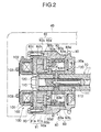
- Fig. 2 is a sectional view of the valve timing change apparatus.
- Fig. 3 is a rear view of an oil pressure generating mechanism which forms a part of the valve timing change apparatus.
- Fig. 4 is a rear view and a sectional view of each disassembled part of the oil pressure generating mechanism.
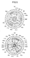
- Fig. 5 shows a connecting passage of the oil pressure generating mechanism and the inside of an angle change mechanism; (a) is a front view and (b) is a rear view.
- Fig. 1 through 5 show an embodiment of a valve timing change apparatus of the present invention.
- Fig. 1 is an abbreviated schematic drawing.
- Fig. 2 is a sectional view of a main part.
- Fig. 3 is a rear view of an oil pressure generating mechanism.
- Fig. 4 is an exploded view of the oil pressure generating mechanism.
- Fig. 5 is a front view and a rear view of an angle change mechanism.
- an internal combustion engine to which the apparatus is mounted comprises a cam shaft 10 driving an intake valve or an exhaust valve, a crank shaft 20 making a piston reciprocate, a chain 21 transmitting rotational drive force of the crank shaft 20 to the cam shaft 10, a sprocket 30 as a rotational drive member, a cylinder head cover 40, a crank angle sensor 50 detecting rotational angle of the crank shaft 20, a cam angle sensor 60 detecting rotational angle of the cam shaft 10, an engine control unit (ECU) 70 controlling engine operation, and so on.
- ECU engine control unit
- the apparatus is to set the open-close timing of the valve in accordance with engine drive modes by changing the relative angle position between the cam shaft 10 and the sprocket 30 in the rotating direction.
- the apparatus comprises an angle change mechanism 80 for changing and holding the relative angle position between the cam shaft 10 and the sprocket 30 by oil pressure, an oil pressure generating mechanism 90 generating oil pressure by relative rotation for driving the angle change mechanism 80, an electromagnetic retarder 100 as a drive means for generating relative rotation at the oil pressure generating mechanism 90, and so on.
- the angle change mechanism 80 comprises a housing rotor 82 as a cylindrical first rotate member in which a separating wall 81 is disposed, a vane rotor 83 as a second rotate member disposed being reciprocatable within a specific angle range in the space (of one side of the separating wall 81) inside the housing rotor 82, and so on.
- the housing rotor 82 is rotatably supported coaxially to the cam shaft 10 by a cylindrical spacer 120 fitted to the outside of a bolt 110 which is fastened to the cam shaft 10.
- the sprocket 30 which is rotatably supported by the cam shaft 10 is fixed to the end surface of the housing rotor 82 to rotate integrally.
- the vane rotor 83 has three vane portions 83a and a hub portion 83b.
- a seal 83a' intimately contacting to an inner circumference 82a of the housing rotor 82 is disposed at the top end of the vane portion 83a.
- a piercing hole 83b' as a lubricating oil passage, and three passages 83b" as lubricating oil passages connecting to the piercing hole 83b' and extending to open in the diameter direction are formed at the hub portion 83b. Then, the hub portion 83b is fastened by the bolt 110 being sandwiched with the end surfaces of the cylindrical spacer 120 and the cam shaft 10.
- a passage 111 connecting to the lubricating oil passage 11 formed in the cam shaft 10, and a passage 112 connecting to the piercing hole 83b' and the passages 83b" are formed in the bolt 110.
- Engine lubricating oil as the operating oil introduced through the lubricating oil passage 11 is led into a retarding oil chamber RC, which is explained later, via the passages 111, 112, the piercing hole 83b', and the passages 83b".
- the lubricating oil passage 11 introduces the engine lubricating oil supplied by an oil pump via a lubricating oil passage OG formed in a cylinder block.
- the vane rotor 83 integrally rotates with the cam shaft 10. Further, the vane rotor 83 can rotate relatively to the housing rotor 82 within a specific angle range in the space defined by the separating wall 81 and the inner circumference 82a of the housing rotor 82, and the front surface 30a of the sprocket 30.
- the housing rotor 82 and the vane rotor 83 form the advancing oil chamber AC and the retarding oil chamber RC to and from which the lubricating oil is charged and discharged, to rotate the cam shaft 10 to the advancing side or the retarding side with the operation of the oil pressure generating mechanism 90.
- a torsion spring 130 is disposed between the sprocket 30 and the cam shaft 10.
- the torsion spring 130 exerts the spring force in the direction to rotate the cam shaft 10 counterclockwise in Fig. 5(a) against the sprocket 30 (and the housing rotor 82).
- the cam shaft 10 (the vane rotor 83) is rotated to and held at the most retarded angle position by the spring force of the torsion spring 130.
- the oil pressure generating mechanism 90 comprises a casing 91, a rotor 92 rotatably accommodated in the casing 91, a connecting passage 93 formed at the separating passage 81, and so on.
- the casing 91 has a brake drum 91a which is rotatably supported coaxially to the cam shaft 10 between the outer circumference of the cylindrical spacer 120 and the inner circumference 82b of the housing rotor 82 and which movement in the thrust direction is restricted by the separating wall 81 and a stopper ring 82c, and a plate 91b connected to the brake drum 91a.
- a suck port 91b' sucking the lubricating oil inside, and an eject port 91b" ejecting the lubricating oil outside are formed at the plate 91b.
- the rotor 92 has an inner rotor 92a rotating coaxially to the rotation center of the casing 91 (namely, the cam shaft 10), and an outer rotor 92b which rotation center is deviated by a specific amount and which is rotated being engaged with the inner rotor 92a. Further, the inner rotor 92a is connected to the separating wall 81 by a pin 92a', and rotates integrally with the housing rotor 82.
- a connecting passage 93 for flowing the lubricating oil is formed at the separating wall 81.
- the connecting passage 93 has a first annular passage 93a connected to the suck port 91b' and a second annular passage 93b connected to the eject port 91b" being approximately coaxial to the cam shaft 10, a first piercing hole 93c connecting the first annular passage 93a to the retarding oil chamber RC, and a second piercing hole 93d connecting the second annular passage 93b to the advancing oil chamber AC.
- the rotor 92 rotatably accommodated in the casing 91 defines an expansion-compression room V which expands to suck the lubricating oil from the suck port 91b' and compresses to eject the sucked lubricating oil through the eject port 91b", (while the inner rotor 92a and the outer rotor 92b work together), as shown in Fig. 3 and Fig. 4(b).
- the oil pressure generating mechanism 90 works as a trochoid pump. That is, the pump effect, to suck the lubricating oil into the suck port 91b' from the retarding oil chamber RC via the first piercing hole 93c and the first annular passage 93a, and to eject the lubricating oil to the advancing oil chamber AC from the eject port 91b" via the second annular passage 93b and the second piercing hole 93d, is obtained. In this manner, the oil pressure to drive the angle change mechanism 80 is generated. On the contrary, when the casing 91 rotates integrally with the rotor 92, the abovementioned pump effect cannot be obtained and the oil pressure to drive the angle change mechanism 80 cannot be generated.
- connecting passage 93 is formed at the separating wall 81 of the housing rotor 82 as the first rotate member, dedicated member for defining the connecting passage is not needed and the structure can be simplified. Furthermore, since the oil pressure generating mechanism 90 and the angle change mechanism 80 are disposed being adjacent to each other sandwiching the separating wall 81, the connecting passage 93 can be set short to a minimum and oil pressure drop by flow resistance etc. can be suppressed.
- the lubricating oil flow (namely, exchanging) between the angle change mechanism 80 and the oil pressure generating mechanism 90 can be reliably performed without regard to the relative angle positions. Therefore, the change operation of the open-close timing of the valve can be reliably performed.
- the electromagnetic retarder 100 has an approximately annular case 101 disposed being adjacent to the brake drum 91a and being coaxial to the cam shaft 10, an electromagnetic coil 102 accommodated in the case 101, and so on. Then, the electromagnetic retarder 100 is fixed to the cylinder head cover 40 by fitting with a pin 103 projecting from the end surface of the case 101.
- angle change mechanism 80 since the angle change mechanism 80, the oil pressure generating mechanism 90, and the electromagnetic retarder 100 are arranged coaxially to the cam shaft 10, angle change operation by oil pressure, oil pressure generating operation (pump effect), and activating operation of oil pressure generating are performed in the vicinity including the axis of the cam shaft 10. Therefore, each operation is efficiently performed while eliminating waste. Further, since each structural part is aggregated towards the axis of the cam shaft 10, the apparatus becomes compact.
- a drive mode of an engine is determined by the ECU 70 being based on detect signals of the crank angle sensor 50 and the cam angle sensor 60 etc.
- the operation of the electromagnetic retarder 100 namely ON/OFF of powering to the electromagnetic coil 102 and magnitude of current etc., is controlled.
- the lubricating oil charged into the retarding oil chamber RC is sucked into the rotor 92 from the suck port 91b' via the first piercing hole 93c and the first annular passage 93a. Then, the compressed lubricating oil by the rotor 92 is ejected from the eject port 91b", and introduced into the advancing oil chamber AC via the second annular passage 93b and the second piercing hole 93d.
- the pumping operation is controlled to have the adequate discharge characteristic, by adequately controlling the powering to the electromagnetic coil 102 so as to change the magnitude of braking torque and adequately control the rotation speed of the casing 91.
- the oil pressure in the advancing oil chamber AC overcomes the spring force of the torsion spring 130, and the vane rotor 83, namely the cam shaft 10, is rotated to a desired angle position at the advancing side against the sprocket 30. Then, the vane rotor 83 is held at the angle position where the spring force of the torsion spring 130 and the oil pressure of the lubricating oil discharged by the oil pressure generating mechanism 90 are in balance (namely, close to each other).
- the oil pressure generating mechanism 90 utilizes the lubricating oil which is previously introduced to the angle change mechanism 80 to generate oil pressure (namely, to supply the lubricating oil) for driving the angle change mechanism 80.
- oil pressure namely, to supply the lubricating oil
- the structure having the housing rotor 82, the vane rotor 83, the advancing oil chamber AC, the retarding oil chamber RC, etc. is adopted as the angle change mechanism.
- another structure can be adapted as long as the relative angle position between the cam shaft 10 and the sprocket 30 can be changed.
- the structure that the angle change mechanism 80, the oil pressure generating mechanism 90, and the electromagnetic retarder 100 are coaxially arranged is shown.
- a structure disposing the oil pressure generating mechanism and the electromagnetic retarder at another position, connecting the oil pressure generating mechanism and the angle change mechanism with an operating oil passage etc., and driving the oil pressure generating mechanism separately can be adopted.
- the sprocket 30 is shown as a rotational drive member to transmit rotational drive force of the crank shaft to the cam shaft 10.
- a timing pulley or the like which transmits rotational drive force of the crank shaft by a belt.
- the rotor 92 of the oil pressure generating mechanism 90 the inner rotor 92a and the outer rotor 92b which form a trochoid pump are shown.
- the valve timing change apparatus of the present invention comprises an angle change mechanism for changing and holding the relative angle position between a cam shaft and a rotational drive member (namely, a sprocket etc.) by oil pressure, an oil pressure generating mechanism for driving the angle change mechanism, a drive means for driving the oil pressure generating mechanism, and so on.
Landscapes
- Engineering & Computer Science (AREA)
- Mechanical Engineering (AREA)
- General Engineering & Computer Science (AREA)
- Valve Device For Special Equipments (AREA)
Abstract
The valve timing change apparatus of the present invention is the
apparatus for changing the relative angle position between a cam shaft 10 and a
sprocket 30, which comprises an angle change mechanism 80 changing and
holding the relative angle position between the cam shaft 10 and the sprocket 30
by oil pressure, an oil pressure generating mechanism 90 generating oil pressure
for driving the angle change mechanism 80 by relative rotation, and an
electromagnetic retarder 100 generating relative rotation at the oil pressure
generating mechanism 90. With this structure, simplification and downsizing of
the apparatus, reduction of engine load, suppression of oil pressure drop, etc. can
be obtained. Then, a plurality of the apparatus can be mounted on an engine.
In this manner, downsizing of the valve timing change apparatus, reduction of
engine load, downsizing of an oil pump, etc. can be obtained.
Description
- The present invention relates to a valve timing change apparatus which changes the open-close timing of at least one of an intake valve and an exhaust valve of an internal combustion engine.
- As a conventional valve timing change apparatus to change the open-close timing of an intake valve or an exhaust valve of an internal combustion engine, the structure which changes the rotational phases of a cam shaft to drive the intake valve or the exhaust valve and a crank shaft is known. For example, such a structure is disclosed in Japanese Patent No. 3033582, Japanese Patent laid-open 2000-274215, etc.
- The apparatus disclosed in Japanese Patent No. 3033582 comprises an advancing oil-pressure chamber and a retarding oil-pressure chamber disposed at both sides of a vane which rotates within a specific angle range in a housing, and a lubricating oil passage communicating with both oil-pressure chambers. Then, by a switching valve (namely, an oil control valve) disposed at some midpoint of the lubricating oil passage, the lubricating oil introduced to both chambers is appropriately controlled, and pressure difference between both chambers is relatively generated. In this manner, the rotational phases of the cam shaft and the crank shaft are changed.
- Further, with the apparatus disclosed in Japanese Patent Laid-open 2000-274215, relative rotation is generated between a specific rotating member and a cam shaft by electromagnetically generated braking torque, and the rotational phases of the cam shaft and the crank shaft are changed via a gear mechanism, such as a worm gear, a hypoid gear, etc.
- However, with the apparatus disclosed in Japanese Patent No. 3033582, since the switching valve disposed at some midpoint of the lubricating oil passage switches the flow of the lubricating oil and directly controls the charge and discharge of the lubricating oil, the driving force of a pump for supplying the lubricating oil is directly added as a load to the engine. Further, oil pressure drop is caused while passing though the lubricating oil passage. The drop of the oil pressure becomes significant, especially when this apparatus is disposed at both the intake side and the exhaust side (namely, two-apparatuses mounted), or when two apparatuses are respectively disposed at each cylinder head of both sides of a V-shaped engine (namely, four-apparatuses mounted). When the oil pressure drops as mentioned above, the change to desirable open-close timing cannot be reliably performed.
- On the other hand, to prevent the oil pressure drop, the capacity of the pump for supplying lubricating oil has to be enlarged, which causes upsizing of an engine, increase of an engine load, etc.
- With the apparatus disclosed in Japanese Patent Laid-open 2000-274215, problems such as impact noise of the teeth caused by backlash etc. of the gears, phase fluctuation caused by thrust play at the hypoid gear, etc. arise. Further, because it is a gear mechanism, the apparatus becomes mechanically complicated and upsized, which causes upsizing of an engine.
- The present invention was devised in view of the problems of the related art. The object of the present invention is to provide a valve timing change apparatus which can reliably change the open-close timing at all drive modes of an engine, without being affected by lubricating oil supply capacity, circumstance conditions, etc., while achieving load reduction to the engine, structural simplification, downsizing, and so on.
- The valve timing change apparatus of the present invention is for changing open-close timing of an intake valve or an exhaust valve of an internal combustion engine, by changing the relative angle position in the rotating direction between a cam shaft which drives the valve and a rotational drive member which receives rotational drive force of a crank shaft to rotate the cam shaft, which comprises an angle change mechanism changing and holding the relative angle position between the cam shaft and the rotational drive member by oil pressure, an oil pressure generating mechanism generating oil pressure for driving the angle change mechanism by relative rotation, and a drive means generating relative rotation at the oil pressure generating mechanism.
- With this structure, when the drive means operates, relative rotation is generated at the oil pressure generating mechanism, and oil pressure is generated. The angle change mechanism is driven by the oil pressure, and the angle position of the cam shaft in the rotating direction is changed against the rotational drive member (for example, a sprocket, a timing pulley or the like). In this manner, the open-close timing of the valve is changed in accordance with engine conditions. Particularly, by adopting the oil pressure generating mechanism and the drive means, simplification and downsizing of the structure is obtained, and engine load is reduced, and oil pressure drop is suppressed. Therefore, a plurality of the apparatuses can be mounted on an engine. Further, change operation of open-close timing of a valve can be reliably performed at all drive modes of an engine.
- In the abovementioned structure, the angle change mechanism, the oil pressure generating mechanism, and the drive means can be arranged coaxially to the cam shaft.
- With this structure, angle change operation of the angle change mechanism, oil pressure generating operation of the oil pressure generating mechanism, and drive operation of the drive means are performed in the vicinity including the axis of the cam shaft. Therefore, each operation is efficiently performed while eliminating waste. Further, since each structural part is aggregated towards the axis of the cam shaft, the apparatus becomes compact.
- In the abovementioned structure, the angle change mechanism can be arranged so that the angle position of the cam shaft against the rotational drive member moves in one direction by oil pressure and in the other direction by spring force.
- With this structure of the angle change mechanism, one of advancing operation and retarding operation is performed by oil pressure, and the other of advancing operation and retarding operation is performed by the urging force of the spring. Consequently, since oil pressure is utilized only for either operation, operating oil consumption is reduced. Further, since the energy for generating oil pressure at either operation becomes unnecessary, engine load is reduced.
- In the abovementioned structure, it is possible that the angle change mechanism has a first rotate member rotating integrally with the rotational drive member and a second rotate member rotating integrally with the cam shaft, and the first rotate member and the second rotate member define an advancing oil chamber and a retarding oil chamber to and from which the operating oil is charged and discharged, to rotate the cam shaft to the advancing side or the retarding side against the rotational drive member, and the oil pressure generating mechanism has a rotor defining an expansion-compression room of the operating oil while rotating integrally with the first rotate member and a casing rotatably supported so that the rotor sucks and ejects the operating oil with relative rotation to the casing, and the drive means has an electromagnetic coil for generating electromagnetic force to exert braking torque to the casing for suppressing rotation.
- With this structure, when the electromagnetic coil is powered and braking torque is generated by the electromagnetic sucking force, the rotation of the casing is suppressed, and relative rotation between the rotor and the casing is generated. Thus, the rotor generates oil pressure by sucking and pressurizing operating oil, and the oil pressure is exerted to the advancing oil chamber or the retarding oil chamber. Then, the cam shaft is rotated to the advancing side or the retarding side against the operational drive means, and is held at a specific angle position. In this manner, by utilizing electromagnetic sucking force, relative rotation can be easily generated at the oil pressure generating mechanism.
- In the abovementioned structure, it is possible that the oil pressure generating mechanism has a connecting passage for sucking the operating oil charged into one of the advancing oil chamber and the retarding oil chamber, and ejecting the operating oil towards the other of the advancing oil chamber and the retarding oil chamber.
- With this structure, the operating oil introduced to the angle change mechanism is effectively utilized via the connecting passage as the operating oil for the oil pressure generating mechanism. Therefore, wasteful consumption of the operating oil can be reduced. Then, compared with the case of supplying the operating oil separately, engine load reduces and the engine power improves.
- In the abovementioned structure, it is possible that the oil pressure generating mechanism is disposed adjacent to the first rotate member, and the connecting passage is formed at the first rotate member.
- With this structure, dedicated member for defining the connecting passage is not needed and the structure is simplified. Further, since the oil pressure generating mechanism and the angle change mechanism are disposed being adjacent to each other, the connecting passage can be set short to a minimum and oil pressure drop etc. can be suppressed.
- In the abovementioned structure, it is possible that the connecting passage comprises a first annular passage and a second annular passage formed approximately coaxially to the cam shaft and respectively connected to a suck port and an eject port of the oil pressure generating mechanism, and a first piercing hole and a second piercing hole respectively connecting the first annular passage and the second annular passage respectively to the retarding oil chamber and the advancing oil chamber.
- With this structure, when rotation of the casing is suppressed and relative rotation between the casing and the rotor is generated, the operating oil in the retarding oil chamber is sucked through the suck port of the oil pressure generating mechanism via the first piercing hole and the first annular passage. Then, the pressurized operating oil is ejected through the eject port of the oil pressure generating mechanism and supplied into the advancing oil chamber via the second annular passage and the second piercing hole. In this manner, advancing operation is performed. Since the connecting passage (namely, the first annular passage) to connect the suck port with the retarding oil chamber and the connecting passage (namely, the second annular passage) to connect the eject port with the advancing oil chamber are formed in an annular shape, the operating oil flow (namely, exchanging) between the angle change mechanism and the oil pressure generating mechanism can be performed without regard to the relative angle positions. Therefore, the change operation can be reliably performed.
- In the abovementioned structure, it is possible that the rotor has an inner rotor directly connected to the first rotate member, and an outer rotor defining the expansion-compression room of the operating oil with the inner rotor.
- With this structure, when the rotation of the casing is suppressed and relative rotation between the casing and the rotor is generated, the sucking operation and the ejecting operation of the operating oil is performed while the inner rotor and the outer rotor (for example, two rotors forming a trochoid pump, two rotors forming a gear pump, or the like) work together.
- In the abovementioned structure, it is possible that the angle change mechanism has an oil passage to introduce lubricating oil of an internal combustion engine.
- With this structure, engine lubricating oil is supplied to the angle change mechanism as the operating oil. Since the oil pressure generating mechanism generates oil pressure separately, the energy to supply the lubricating oil can be reduced than that of a conventional case, and engine load can be reduced.
- Fig. 1 is an abbreviated schematic drawing showing an embodiment of a valve timing change apparatus of the present invention.
- Fig. 2 is a sectional view of the valve timing change apparatus.
- Fig. 3 is a rear view of an oil pressure generating mechanism which forms a part of the valve timing change apparatus.
- Fig. 4 is a rear view and a sectional view of each disassembled part of the oil pressure generating mechanism.
- Fig. 5 shows a connecting passage of the oil pressure generating mechanism and the inside of an angle change mechanism; (a) is a front view and (b) is a rear view.
- The embodiments of the present invention are explained in the following with reference to the attached drawings.
- Fig. 1 through 5 show an embodiment of a valve timing change apparatus of the present invention. Fig. 1 is an abbreviated schematic drawing. Fig. 2 is a sectional view of a main part. Fig. 3 is a rear view of an oil pressure generating mechanism. Fig. 4 is an exploded view of the oil pressure generating mechanism. Fig. 5 is a front view and a rear view of an angle change mechanism.
- As shown in Fig. 1, an internal combustion engine to which the apparatus is mounted comprises a
cam shaft 10 driving an intake valve or an exhaust valve, acrank shaft 20 making a piston reciprocate, achain 21 transmitting rotational drive force of thecrank shaft 20 to thecam shaft 10, asprocket 30 as a rotational drive member, acylinder head cover 40, acrank angle sensor 50 detecting rotational angle of thecrank shaft 20, acam angle sensor 60 detecting rotational angle of thecam shaft 10, an engine control unit (ECU) 70 controlling engine operation, and so on. - Here, the apparatus is to set the open-close timing of the valve in accordance with engine drive modes by changing the relative angle position between the
cam shaft 10 and thesprocket 30 in the rotating direction. As shown in Fig. 2, the apparatus comprises anangle change mechanism 80 for changing and holding the relative angle position between thecam shaft 10 and thesprocket 30 by oil pressure, an oilpressure generating mechanism 90 generating oil pressure by relative rotation for driving theangle change mechanism 80, anelectromagnetic retarder 100 as a drive means for generating relative rotation at the oilpressure generating mechanism 90, and so on. - As shown in Fig. 2 through 5, the
angle change mechanism 80 comprises ahousing rotor 82 as a cylindrical first rotate member in which a separatingwall 81 is disposed, avane rotor 83 as a second rotate member disposed being reciprocatable within a specific angle range in the space (of one side of the separating wall 81) inside thehousing rotor 82, and so on. - The
housing rotor 82 is rotatably supported coaxially to thecam shaft 10 by acylindrical spacer 120 fitted to the outside of abolt 110 which is fastened to thecam shaft 10. Thesprocket 30 which is rotatably supported by thecam shaft 10 is fixed to the end surface of thehousing rotor 82 to rotate integrally. - As shown in Fig. 2 though 5, the
vane rotor 83 has threevane portions 83a and ahub portion 83b. Aseal 83a' intimately contacting to an inner circumference 82a of thehousing rotor 82 is disposed at the top end of thevane portion 83a. A piercinghole 83b' as a lubricating oil passage, and threepassages 83b" as lubricating oil passages connecting to the piercinghole 83b' and extending to open in the diameter direction are formed at thehub portion 83b. Then, thehub portion 83b is fastened by thebolt 110 being sandwiched with the end surfaces of thecylindrical spacer 120 and thecam shaft 10. - A
passage 111 connecting to the lubricatingoil passage 11 formed in thecam shaft 10, and apassage 112 connecting to the piercinghole 83b' and thepassages 83b" are formed in thebolt 110. Engine lubricating oil as the operating oil introduced through the lubricatingoil passage 11 is led into a retarding oil chamber RC, which is explained later, via thepassages hole 83b', and thepassages 83b". Here, the lubricatingoil passage 11 introduces the engine lubricating oil supplied by an oil pump via a lubricating oil passage OG formed in a cylinder block. - With this structure, the
vane rotor 83 integrally rotates with thecam shaft 10. Further, thevane rotor 83 can rotate relatively to thehousing rotor 82 within a specific angle range in the space defined by the separatingwall 81 and the inner circumference 82a of thehousing rotor 82, and thefront surface 30a of thesprocket 30. - Consequently, as shown in Fig. 5(b), the
housing rotor 82 and thevane rotor 83 form the advancing oil chamber AC and the retarding oil chamber RC to and from which the lubricating oil is charged and discharged, to rotate thecam shaft 10 to the advancing side or the retarding side with the operation of the oilpressure generating mechanism 90. - As shown in Fig. 2, a
torsion spring 130 is disposed between thesprocket 30 and thecam shaft 10. Thetorsion spring 130 exerts the spring force in the direction to rotate thecam shaft 10 counterclockwise in Fig. 5(a) against the sprocket 30 (and the housing rotor 82). - Therefore, in the state that the advancing oil chamber AC is not filled with the lubricating oil, the cam shaft 10 (the vane rotor 83) is rotated to and held at the most retarded angle position by the spring force of the
torsion spring 130. - In this manner, since the retarding operation of the
angle change mechanism 80 is performed by the spring force of thetorsion spring 130, the corresponding energy to generate the oil pressure for retarding becomes unnecessary. Consequently, engine load etc. is reduced and oil consumption is also reduced. - As shown in Fig. 2 through 4, the oil
pressure generating mechanism 90 comprises acasing 91, arotor 92 rotatably accommodated in thecasing 91, a connecting passage 93 formed at the separatingpassage 81, and so on. - The
casing 91 has abrake drum 91a which is rotatably supported coaxially to thecam shaft 10 between the outer circumference of thecylindrical spacer 120 and theinner circumference 82b of thehousing rotor 82 and which movement in the thrust direction is restricted by the separatingwall 81 and astopper ring 82c, and aplate 91b connected to thebrake drum 91a. Asuck port 91b' sucking the lubricating oil inside, and aneject port 91b" ejecting the lubricating oil outside are formed at theplate 91b. - The
rotor 92 has aninner rotor 92a rotating coaxially to the rotation center of the casing 91 (namely, the cam shaft 10), and anouter rotor 92b which rotation center is deviated by a specific amount and which is rotated being engaged with theinner rotor 92a. Further, theinner rotor 92a is connected to the separatingwall 81 by apin 92a', and rotates integrally with thehousing rotor 82. - A connecting passage 93 for flowing the lubricating oil is formed at the separating
wall 81. As shown in Fig. 2 through 5, the connecting passage 93 has a firstannular passage 93a connected to thesuck port 91b' and a secondannular passage 93b connected to theeject port 91b" being approximately coaxial to thecam shaft 10, a first piercinghole 93c connecting the firstannular passage 93a to the retarding oil chamber RC, and asecond piercing hole 93d connecting the secondannular passage 93b to the advancing oil chamber AC. - Consequently, in the oil
pressure generating mechanism 90, therotor 92 rotatably accommodated in thecasing 91 defines an expansion-compression room V which expands to suck the lubricating oil from thesuck port 91b' and compresses to eject the sucked lubricating oil through theeject port 91b", (while theinner rotor 92a and theouter rotor 92b work together), as shown in Fig. 3 and Fig. 4(b). - Then, when the
casing 91 rotates slower than therotor 92, (namely, when relative rotation is generated), the oilpressure generating mechanism 90 works as a trochoid pump. That is, the pump effect, to suck the lubricating oil into thesuck port 91b' from the retarding oil chamber RC via the first piercinghole 93c and the firstannular passage 93a, and to eject the lubricating oil to the advancing oil chamber AC from theeject port 91b" via the secondannular passage 93b and thesecond piercing hole 93d, is obtained. In this manner, the oil pressure to drive theangle change mechanism 80 is generated. On the contrary, when thecasing 91 rotates integrally with therotor 92, the abovementioned pump effect cannot be obtained and the oil pressure to drive theangle change mechanism 80 cannot be generated. - As mentioned above, with the oil
pressure generating mechanism 90, since the lubricating oil introduced to theangle change mechanism 80 via the connecting passage 93 is utilized as the operating oil, wasteful consumption of the lubricating oil can be reduced. Compared with the case of supplying the operating oil separately, engine load reduces and the engine power improves. - Further, since the connecting passage 93 is formed at the separating
wall 81 of thehousing rotor 82 as the first rotate member, dedicated member for defining the connecting passage is not needed and the structure can be simplified. Furthermore, since the oilpressure generating mechanism 90 and theangle change mechanism 80 are disposed being adjacent to each other sandwiching the separatingwall 81, the connecting passage 93 can be set short to a minimum and oil pressure drop by flow resistance etc. can be suppressed. - Furthermore, since the first
annular passage 93a and the secondannular passage 93b are adopted, the lubricating oil flow (namely, exchanging) between theangle change mechanism 80 and the oilpressure generating mechanism 90 can be reliably performed without regard to the relative angle positions. Therefore, the change operation of the open-close timing of the valve can be reliably performed. - As shown in Fig. 1 and Fig. 2, the
electromagnetic retarder 100 has an approximatelyannular case 101 disposed being adjacent to thebrake drum 91a and being coaxial to thecam shaft 10, anelectromagnetic coil 102 accommodated in thecase 101, and so on. Then, theelectromagnetic retarder 100 is fixed to thecylinder head cover 40 by fitting with apin 103 projecting from the end surface of thecase 101. - With the
electromagnetic retarder 100, when theelectromagnetic coil 102 is powered, electromagnetic suction force is generated and the casing 91 (thebrake drum 91a) is attracted. In this manner, braking torque to suppress the rotation of thecasing 91 is generated. - Thus, by utilizing electromagnetic suction force as braking torque, relative rotation between the casing 91 of the oil
pressure generating mechanism 90 and therotor 92 can be generated with a simple structure. - As mentioned above, since the
angle change mechanism 80, the oilpressure generating mechanism 90, and theelectromagnetic retarder 100 are arranged coaxially to thecam shaft 10, angle change operation by oil pressure, oil pressure generating operation (pump effect), and activating operation of oil pressure generating are performed in the vicinity including the axis of thecam shaft 10. Therefore, each operation is efficiently performed while eliminating waste. Further, since each structural part is aggregated towards the axis of thecam shaft 10, the apparatus becomes compact. - Next, the operation of the apparatus is explained. Here, a drive mode of an engine is determined by the
ECU 70 being based on detect signals of thecrank angle sensor 50 and thecam angle sensor 60 etc. In accordance with the determined drive mode, the operation of theelectromagnetic retarder 100, namely ON/OFF of powering to theelectromagnetic coil 102 and magnitude of current etc., is controlled. - Firstly, when the
electromagnetic coil 102 is not powered, braking torque is not generated. Since thecasing 91 and therotor 92 integrally rotate, the oilpressure generating mechanism 90 does not generate oil pressure. Therefore, in theangle change mechanism 80, the housing rotor 82 (the sprocket 30) and thecam shaft 10 are returned to a specific relative angle position by the spring force of thetorsion spring 130. Thecam shaft 10 is held at the most retarded angle position against thesprocket 30. - Next, when the
electromagnetic coil 102 is powered based on the control signal of theECU 70, braking torque is generated and the rotation of the casing 91 (brake drum 91a) is suppressed. In this way, relative rotation between therotor 92 and thecasing 91 is generated. Then, the oilpressure generating mechanism 90 is activated and pumping operation starts for sucking and ejecting the lubricating oil. - Consequently, the lubricating oil charged into the retarding oil chamber RC is sucked into the
rotor 92 from thesuck port 91b' via the first piercinghole 93c and the firstannular passage 93a. Then, the compressed lubricating oil by therotor 92 is ejected from theeject port 91b", and introduced into the advancing oil chamber AC via the secondannular passage 93b and thesecond piercing hole 93d. - Here, the pumping operation is controlled to have the adequate discharge characteristic, by adequately controlling the powering to the
electromagnetic coil 102 so as to change the magnitude of braking torque and adequately control the rotation speed of thecasing 91. - With this operation, the oil pressure in the advancing oil chamber AC overcomes the spring force of the
torsion spring 130, and thevane rotor 83, namely thecam shaft 10, is rotated to a desired angle position at the advancing side against thesprocket 30. Then, thevane rotor 83 is held at the angle position where the spring force of thetorsion spring 130 and the oil pressure of the lubricating oil discharged by the oilpressure generating mechanism 90 are in balance (namely, close to each other). - On the contrary, when the powering to the
electromagnetic coil 102 is discontinued based on the control signal of theECU 70, braking torque disappears, and the casing 91 (thebrake drum 91a) and therotor 92 rotate integrally. In this way, the pump operation of the oilpressure generating mechanism 90 is discontinued, and the oil pressure in the advancing oil chamber AC decreases. Then, thecam shaft 10 is rotated to and held at the most retarded angle position by the spring force of thetorsion spring 130. - In this manner, the oil
pressure generating mechanism 90 utilizes the lubricating oil which is previously introduced to theangle change mechanism 80 to generate oil pressure (namely, to supply the lubricating oil) for driving theangle change mechanism 80. Thus, compared with the conventional case of pressurizing and supplying the lubricating oil of the cylinder block side by an oil pump, engine load is reduced and wasteful consumption of the oil is reduced. - In the abovementioned embodiment, as the angle change mechanism, the structure having the
housing rotor 82, thevane rotor 83, the advancing oil chamber AC, the retarding oil chamber RC, etc. is adopted. However, another structure can be adapted as long as the relative angle position between thecam shaft 10 and thesprocket 30 can be changed. - Further, in the abovementioned embodiment, as the operating oil for the
angle change mechanism 80 and the oilpressure generating mechanism 90, engine lubricating oil is adopted. However, since the influence of the heat in this region is smaller than the lubricating oil, a structure storing and circulating dedicated operating oil which is separate from engine lubricating oil can be adopted. - Furthermore, in the abovementioned embodiment, the structure that the
angle change mechanism 80, the oilpressure generating mechanism 90, and theelectromagnetic retarder 100 are coaxially arranged is shown. However, not limited to this structure, a structure disposing the oil pressure generating mechanism and the electromagnetic retarder at another position, connecting the oil pressure generating mechanism and the angle change mechanism with an operating oil passage etc., and driving the oil pressure generating mechanism separately can be adopted. - Furthermore, in the abovementioned embodiment, the
sprocket 30 is shown as a rotational drive member to transmit rotational drive force of the crank shaft to thecam shaft 10. However, not limited to this structure, it is also possible to adopt a timing pulley or the like which transmits rotational drive force of the crank shaft by a belt. Further, as therotor 92 of the oilpressure generating mechanism 90, theinner rotor 92a and theouter rotor 92b which form a trochoid pump are shown. However, not limited to this structure, it is also possible to adopt two rotors which form a gear pump. - As mentioned above, the valve timing change apparatus of the present invention comprises an angle change mechanism for changing and holding the relative angle position between a cam shaft and a rotational drive member (namely, a sprocket etc.) by oil pressure, an oil pressure generating mechanism for driving the angle change mechanism, a drive means for driving the oil pressure generating mechanism, and so on. Thus, simplification and downsizing of the apparatus, reduction of engine load, suppression of oil pressure drop, etc. can be obtained. Then, a plurality of the apparatus can be mounted on an engine. Further, change operation of open-close timing of a valve can be reliably performed at all drive modes of an engine.
Claims (9)
- A valve timing change apparatus for changing open-close timing of an intake valve or an exhaust valve of an internal combustion engine, by changing the relative angle position in the rotating direction between a cam shaft which drives said valve and a rotational drive member which receives rotational drive force of a crank shaft to rotate said cam shaft, comprising:an angle change mechanism changing and holding the relative angle position between said cam shaft and said rotational drive member by oil pressure;an oil pressure generating mechanism generating oil pressure for driving said angle change mechanism by relative rotation; anda drive means generating relative rotation at said oil pressure generating mechanism.
- The valve timing change apparatus according to claim 1, wherein said angle change mechanism, said oil pressure generating mechanism, and said drive means are arranged coaxially to said cam shaft.
- The valve timing change apparatus according to claim 1 or claim 2,
wherein the angle position of said cam shaft against said rotational drive member moves in one direction by oil pressure and in the other direction by spring force. - The valve timing change apparatus according to any one of claims 1 though 3,
wherein said angle change mechanism has a first rotate member rotating integrally with said rotational drive member and a second rotate member rotating integrally with said cam shaft;
wherein said first rotate member and said second rotate member define an advancing oil chamber and a retarding oil chamber to and from which the operating oil is charged and discharged, to rotate said cam shaft to the advancing side or the retarding side against said rotational drive member;
wherein said oil pressure generating mechanism has a rotor defining an expansion-compression room of the operating oil while rotating integrally with said first rotate member, and a casing rotatably supported so that said rotor sucks and ejects the operating oil with relative rotation to said casing; and
wherein said drive means has an electromagnetic coil for generating electromagnetic force to exert braking torque to said casing for suppressing rotation. - The valve timing change apparatus according to claim 4, wherein said oil pressure generating mechanism has a connecting passage for sucking the operating oil charged into one of said advancing oil chamber and said retarding oil chamber, and ejecting the operating oil towards the other of said advancing oil chamber and said retarding oil chamber.
- The valve timing change apparatus according to claim 5, wherein said oil pressure generating mechanism is disposed adjacent to said first rotate member, and said connecting passage is formed at said first rotate member.
- The valve timing change apparatus according to claim 6, wherein said connecting passage comprises a first annular passage and a second annular passage formed approximately coaxially to said cam shaft and respectively connected to a suck port and an eject port of said oil pressure generating mechanism, and a first piercing hole and a second piercing hole respectively connecting said first annular passage and said second annular passage respectively to said retarding oil chamber and said advancing oil chamber.
- The valve timing change apparatus according to any one of claims 4 though 7, wherein said rotor has an inner rotor directly connected to said first rotate member, and an outer rotor defining the expansion-compression room of the operating oil with said inner rotor.
- The valve timing change apparatus according to any one of claims 1 though 8, wherein said angle change mechanism has an oil passage to introduce lubricating oil of an internal combustion engine.
Applications Claiming Priority (3)
| Application Number | Priority Date | Filing Date | Title |
|---|---|---|---|
| JP2002222982A JP2004060591A (en) | 2002-07-31 | 2002-07-31 | Valve timing change device |
| JP2002222982 | 2002-07-31 | ||
| PCT/JP2003/009537 WO2004011778A1 (en) | 2002-07-31 | 2003-07-28 | Valve timing changer |
Publications (1)
| Publication Number | Publication Date |
|---|---|
| EP1544418A1 true EP1544418A1 (en) | 2005-06-22 |
Family
ID=31184944
Family Applications (1)
| Application Number | Title | Priority Date | Filing Date |
|---|---|---|---|
| EP03771382A Withdrawn EP1544418A1 (en) | 2002-07-31 | 2003-07-28 | Valve timing changer |
Country Status (4)
| Country | Link |
|---|---|
| US (1) | US7131409B2 (en) |
| EP (1) | EP1544418A1 (en) |
| JP (1) | JP2004060591A (en) |
| WO (1) | WO2004011778A1 (en) |
Cited By (1)
| Publication number | Priority date | Publication date | Assignee | Title |
|---|---|---|---|---|
| WO2019029786A1 (en) * | 2017-08-07 | 2019-02-14 | HELLA GmbH & Co. KGaA | Apparatus for camshaft timing adjustment with built in pump |
Families Citing this family (5)
| Publication number | Priority date | Publication date | Assignee | Title |
|---|---|---|---|---|
| JP4066967B2 (en) | 2004-03-03 | 2008-03-26 | トヨタ自動車株式会社 | Valve characteristic changing device for internal combustion engine |
| DE102006033425A1 (en) * | 2006-07-19 | 2008-02-21 | Schaeffler Kg | Group of several camshafts with camshaft adjusters |
| JP5585832B2 (en) * | 2010-09-10 | 2014-09-10 | アイシン精機株式会社 | Valve timing control device |
| DE102014209294B4 (en) * | 2013-06-20 | 2026-02-19 | Schaeffler Technologies AG & Co. KG | Actuator setup |
| JP6467896B2 (en) * | 2014-12-08 | 2019-02-13 | 株式会社デンソー | Valve timing adjustment device |
Family Cites Families (11)
| Publication number | Priority date | Publication date | Assignee | Title |
|---|---|---|---|---|
| JPH04132414A (en) | 1990-09-25 | 1992-05-06 | Nec Corp | Prevention circuit for unstable setting |
| DE4116169A1 (en) | 1991-05-17 | 1992-11-19 | Bosch Gmbh Robert | DEVICE FOR ADJUSTING THE TURNING ANGLE ASSIGNMENT OF A CAMSHAFT TO YOUR DRIVE ELEMENT |
| JPH04132414U (en) * | 1991-05-29 | 1992-12-08 | 株式会社アツギユニシア | Internal combustion engine valve timing control device |
| JPH05195728A (en) | 1992-01-22 | 1993-08-03 | Mazda Motor Corp | Variable valve timing device for engine |
| DE4209792C2 (en) | 1992-03-26 | 2002-10-24 | Bosch Gmbh Robert | Hydraulic-mechanical control device |
| DE4237193A1 (en) | 1992-11-04 | 1994-05-05 | Bosch Gmbh Robert | Method for controlling a device for the relative rotation of a shaft and device for the relative rotation of the shaft of an internal combustion engine |
| DE4240075C2 (en) | 1992-11-28 | 2002-08-29 | Bosch Gmbh Robert | Hydraulic actuator |
| JP2000274215A (en) | 1999-03-23 | 2000-10-03 | Unisia Jecs Corp | Valve timing changing device for internal combustion engine |
| JP3546994B2 (en) * | 1999-09-03 | 2004-07-28 | 本田技研工業株式会社 | Oil passage structure of valve train control device of internal combustion engine |
| JP2001271616A (en) | 2000-01-18 | 2001-10-05 | Unisia Jecs Corp | Control device for variable valve mechanism |
| JP2002054408A (en) | 2000-08-14 | 2002-02-20 | Unisia Jecs Corp | Valve timing control device for internal combustion engine |
-
2002
- 2002-07-31 JP JP2002222982A patent/JP2004060591A/en active Pending
-
2003
- 2003-07-28 EP EP03771382A patent/EP1544418A1/en not_active Withdrawn
- 2003-07-28 WO PCT/JP2003/009537 patent/WO2004011778A1/en not_active Ceased
- 2003-07-28 US US10/522,783 patent/US7131409B2/en not_active Expired - Fee Related
Non-Patent Citations (1)
| Title |
|---|
| See references of WO2004011778A1 * |
Cited By (2)
| Publication number | Priority date | Publication date | Assignee | Title |
|---|---|---|---|---|
| WO2019029786A1 (en) * | 2017-08-07 | 2019-02-14 | HELLA GmbH & Co. KGaA | Apparatus for camshaft timing adjustment with built in pump |
| US11352917B2 (en) | 2017-08-07 | 2022-06-07 | HELLA GmbH & Co. KGaA | Apparatus for camshaft timing adjustment with built in pump |
Also Published As
| Publication number | Publication date |
|---|---|
| WO2004011778A1 (en) | 2004-02-05 |
| US20050235935A1 (en) | 2005-10-27 |
| JP2004060591A (en) | 2004-02-26 |
| US7131409B2 (en) | 2006-11-07 |
Similar Documents
| Publication | Publication Date | Title |
|---|---|---|
| US5247914A (en) | Intake- and/or exhaust-valve timing control system for internal combustion engines | |
| US20090107433A1 (en) | Valve timing controller | |
| US5012773A (en) | Intake- and/or exhaust-valve timing control system for internal combustion engine | |
| US5759013A (en) | Oil pump apparatus | |
| US7131409B2 (en) | Valve timing changer | |
| JP2988101B2 (en) | Valve timing control device | |
| US7100555B2 (en) | Valve timing controller | |
| KR100694901B1 (en) | Valve characteristic change device of internal combustion engine | |
| JP3712817B2 (en) | Hybrid gear pump and hydraulic circuit of engine using the same | |
| EP1906017B1 (en) | Compressor | |
| US6439183B1 (en) | Valve timing adjusting device | |
| JP5288043B2 (en) | Variable valve operating device for internal combustion engine | |
| JP2842113B2 (en) | Variable valve timing control device | |
| CN108758312A (en) | Small aero lubricating oil pump and small aero with it | |
| JP3507649B2 (en) | Engine hydraulic circuit | |
| JP3507648B2 (en) | Engine hydraulic circuit | |
| JP3608688B2 (en) | Oil pump device | |
| JP3714131B2 (en) | Valve timing control device | |
| JP4645561B2 (en) | Valve timing control device | |
| JP5782730B2 (en) | Gear oil pump | |
| JP2889586B2 (en) | Valve timing control device for internal combustion engine | |
| JPH11247765A (en) | Hydraulic circuit of compound gear pump and engine | |
| JPH07229408A (en) | Valve timing control device for internal combustion engine | |
| JP2003166408A (en) | Oil pump pressure regulating valve mounting structure | |
| JPH06280515A (en) | Variable valve timing device |
Legal Events
| Date | Code | Title | Description |
|---|---|---|---|
| PUAI | Public reference made under article 153(3) epc to a published international application that has entered the european phase |
Free format text: ORIGINAL CODE: 0009012 |
|
| 17P | Request for examination filed |
Effective date: 20050224 |
|
| AK | Designated contracting states |
Kind code of ref document: A1 Designated state(s): AT BE BG CH CY CZ DE DK EE ES FI FR GB GR HU IE IT LI LU MC NL PT RO SE SI SK TR |
|
| STAA | Information on the status of an ep patent application or granted ep patent |
Free format text: STATUS: THE APPLICATION IS DEEMED TO BE WITHDRAWN |
|
| 18D | Application deemed to be withdrawn |
Effective date: 20080201 |