EP1544415A2 - Stator vane assembly for a gas turbine engine - Google Patents
Stator vane assembly for a gas turbine engine Download PDFInfo
- Publication number
- EP1544415A2 EP1544415A2 EP04257870A EP04257870A EP1544415A2 EP 1544415 A2 EP1544415 A2 EP 1544415A2 EP 04257870 A EP04257870 A EP 04257870A EP 04257870 A EP04257870 A EP 04257870A EP 1544415 A2 EP1544415 A2 EP 1544415A2
- Authority
- EP
- European Patent Office
- Prior art keywords
- outer shroud
- gas turbine
- stator assembly
- recited
- turbine engine
- Prior art date
- Legal status (The legal status is an assumption and is not a legal conclusion. Google has not performed a legal analysis and makes no representation as to the accuracy of the status listed.)
- Granted
Links
- XAGFODPZIPBFFR-UHFFFAOYSA-N aluminium Chemical compound [Al] XAGFODPZIPBFFR-UHFFFAOYSA-N 0.000 claims description 9
- 229910052782 aluminium Inorganic materials 0.000 claims description 9
- RTAQQCXQSZGOHL-UHFFFAOYSA-N Titanium Chemical compound [Ti] RTAQQCXQSZGOHL-UHFFFAOYSA-N 0.000 claims description 7
- 229910052719 titanium Inorganic materials 0.000 claims description 7
- 239000010936 titanium Substances 0.000 claims description 7
- 230000007704 transition Effects 0.000 claims description 4
- 238000010276 construction Methods 0.000 claims 2
- 238000011144 upstream manufacturing Methods 0.000 claims 2
- 230000012010 growth Effects 0.000 abstract description 4
- 239000007789 gas Substances 0.000 description 14
- 238000003491 array Methods 0.000 description 4
- 230000008901 benefit Effects 0.000 description 4
- 230000000712 assembly Effects 0.000 description 3
- 238000000429 assembly Methods 0.000 description 3
- 150000001875 compounds Chemical class 0.000 description 2
- 239000000463 material Substances 0.000 description 2
- 238000012986 modification Methods 0.000 description 2
- 230000004048 modification Effects 0.000 description 2
- 230000000717 retained effect Effects 0.000 description 2
- 238000007789 sealing Methods 0.000 description 2
- 238000012423 maintenance Methods 0.000 description 1
- 238000004382 potting Methods 0.000 description 1
- 238000010248 power generation Methods 0.000 description 1
- 230000002035 prolonged effect Effects 0.000 description 1
- 230000003068 static effect Effects 0.000 description 1
Images


Classifications
-
- F—MECHANICAL ENGINEERING; LIGHTING; HEATING; WEAPONS; BLASTING
- F01—MACHINES OR ENGINES IN GENERAL; ENGINE PLANTS IN GENERAL; STEAM ENGINES
- F01D—NON-POSITIVE DISPLACEMENT MACHINES OR ENGINES, e.g. STEAM TURBINES
- F01D9/00—Stators
- F01D9/02—Nozzles; Nozzle boxes; Stator blades; Guide conduits, e.g. individual nozzles
-
- F—MECHANICAL ENGINEERING; LIGHTING; HEATING; WEAPONS; BLASTING
- F01—MACHINES OR ENGINES IN GENERAL; ENGINE PLANTS IN GENERAL; STEAM ENGINES
- F01D—NON-POSITIVE DISPLACEMENT MACHINES OR ENGINES, e.g. STEAM TURBINES
- F01D25/00—Component parts, details, or accessories, not provided for in, or of interest apart from, other groups
- F01D25/24—Casings; Casing parts, e.g. diaphragms, casing fastenings
- F01D25/246—Fastening of diaphragms or stator-rings
-
- F—MECHANICAL ENGINEERING; LIGHTING; HEATING; WEAPONS; BLASTING
- F01—MACHINES OR ENGINES IN GENERAL; ENGINE PLANTS IN GENERAL; STEAM ENGINES
- F01D—NON-POSITIVE DISPLACEMENT MACHINES OR ENGINES, e.g. STEAM TURBINES
- F01D5/00—Blades; Blade-carrying members; Heating, heat-insulating, cooling or antivibration means on the blades or the members
-
- F—MECHANICAL ENGINEERING; LIGHTING; HEATING; WEAPONS; BLASTING
- F01—MACHINES OR ENGINES IN GENERAL; ENGINE PLANTS IN GENERAL; STEAM ENGINES
- F01D—NON-POSITIVE DISPLACEMENT MACHINES OR ENGINES, e.g. STEAM TURBINES
- F01D9/00—Stators
- F01D9/02—Nozzles; Nozzle boxes; Stator blades; Guide conduits, e.g. individual nozzles
- F01D9/04—Nozzles; Nozzle boxes; Stator blades; Guide conduits, e.g. individual nozzles forming ring or sector
- F01D9/042—Nozzles; Nozzle boxes; Stator blades; Guide conduits, e.g. individual nozzles forming ring or sector fixing blades to stators
-
- F—MECHANICAL ENGINEERING; LIGHTING; HEATING; WEAPONS; BLASTING
- F02—COMBUSTION ENGINES; HOT-GAS OR COMBUSTION-PRODUCT ENGINE PLANTS
- F02C—GAS-TURBINE PLANTS; AIR INTAKES FOR JET-PROPULSION PLANTS; CONTROLLING FUEL SUPPLY IN AIR-BREATHING JET-PROPULSION PLANTS
- F02C9/00—Controlling gas-turbine plants; Controlling fuel supply in air- breathing jet-propulsion plants
- F02C9/16—Control of working fluid flow
- F02C9/18—Control of working fluid flow by bleeding, bypassing or acting on variable working fluid interconnections between turbines or compressors or their stages
-
- F—MECHANICAL ENGINEERING; LIGHTING; HEATING; WEAPONS; BLASTING
- F04—POSITIVE - DISPLACEMENT MACHINES FOR LIQUIDS; PUMPS FOR LIQUIDS OR ELASTIC FLUIDS
- F04D—NON-POSITIVE-DISPLACEMENT PUMPS
- F04D29/00—Details, component parts, or accessories
- F04D29/40—Casings; Connections of working fluid
- F04D29/52—Casings; Connections of working fluid for axial pumps
- F04D29/54—Fluid-guiding means, e.g. diffusers
- F04D29/541—Specially adapted for elastic fluid pumps
- F04D29/542—Bladed diffusers
-
- F—MECHANICAL ENGINEERING; LIGHTING; HEATING; WEAPONS; BLASTING
- F04—POSITIVE - DISPLACEMENT MACHINES FOR LIQUIDS; PUMPS FOR LIQUIDS OR ELASTIC FLUIDS
- F04D—NON-POSITIVE-DISPLACEMENT PUMPS
- F04D29/00—Details, component parts, or accessories
- F04D29/60—Mounting; Assembling; Disassembling
- F04D29/64—Mounting; Assembling; Disassembling of axial pumps
- F04D29/644—Mounting; Assembling; Disassembling of axial pumps especially adapted for elastic fluid pumps
-
- F—MECHANICAL ENGINEERING; LIGHTING; HEATING; WEAPONS; BLASTING
- F05—INDEXING SCHEMES RELATING TO ENGINES OR PUMPS IN VARIOUS SUBCLASSES OF CLASSES F01-F04
- F05D—INDEXING SCHEME FOR ASPECTS RELATING TO NON-POSITIVE-DISPLACEMENT MACHINES OR ENGINES, GAS-TURBINES OR JET-PROPULSION PLANTS
- F05D2240/00—Components
- F05D2240/55—Seals
Definitions
- the present invention relates to a stator assembly, and more particularly to a low-pressure compressor exit stator assembly which interfaces with a full hoop outer shroud pressure vessel within a gas turbine engine.
- a gas turbine engine typically includes a rotor assembly which extends axially through the engine.
- a stator assembly is spaced radially from the rotor assembly and includes an engine case which circumscribes the rotor assembly.
- a flow path for working medium gases is defined within the case. The flow path extends generally axially between the stator assembly and the rotor assembly.
- the rotor assembly includes arrays of rotor blades.
- the arrays of rotor blades extend radially outward across the working medium flow path in proximity with the case.
- Arrays of stator vane assemblies are interdigitated with the arrays of rotor blades.
- the stator vanes extend inward from the case across the working medium flow path into proximity with the rotor assembly to guide the working medium gases when discharged from the rotor blades.
- An exit stator vane assembly typically includes a multiple of stator vanes, an outer case, and an inner case, which extend circumferentially about the working medium flow path.
- Conventional stator vane assemblies utilize a pierced aluminum outer shroud that receives the vane tip through the shroud and provide surface area for potting with a rubber compound. The rubber compound provides a seal between the flow path and an intermediate case core compartment area.
- the outer shroud is supported by the intermediate case at the rear and allowed to "float" radially through a bayonet attachment.
- the material of the outer shroud typically differs from the stator vanes and attachment interfaces.
- the outer shroud is typically manufactured of aluminum for weight/cost and material compatibility with an aluminum bleed duct, whereas other stator assembly components are manufactured of titanium for increased strength. Titanium and aluminum have different thermal growths and the dimensional changes which result from temperature excursions during operation have to be absorbed at the outer shroud to bleed duct interface. That is, the outer shroud section bends or flexes to manage the level of stresses and contact loads through deflection.
- conventional pierced shroud arrangements may not effectively withstand the high pressure and temperature environments in modem gas turbine engines over prolonged time periods.
- Some outer shrouds are of a full hoop geometry to create an uninterrupted vessel which withstands the high pressure and temperature environments typical of advanced gas turbine engines.
- a full hoop design may be too stiff to permit conventional stress management through shroud flexibility.
- Mounting or a full hoop outer shroud have heretofore required relatively complicated attachment arrangements which limits full hoop outer shroud utilization to certain areas within the gas turbine engine.
- stator assembly with a full hoop outer shroud that satisfies the mounting, leakage, durability and thermally induced deflection requirements common to a gas turbine engine.
- a preferred low pressure compressor exit stator assembly includes a multiple of vanes mounted between a full hoop outer shroud and an inner shroud.
- the outer shroud is supported against an intermediate case structure and allowed to float radially through a bayonet arrangement.
- the inner shroud is bolted to the intermediate case.
- the outer shroud is manufactured of aluminum and the inner shroud is manufactured of titanium. Titanium and aluminum have different thermal growths and the dimensional changes which result from temperature excursions during operation are absorbed at the outer shroud to bleed duct interface through a seal located therebetween. The seal accommodates the thermal mismatch.
- the present invention therefore provides a stator assembly with a full hoop outer shroud that satisfies the mounting, leakage, durability, and thermally induced deflection requirements common to a gas turbine engine.
- Figure 1 illustrates a general schematic sectional view of a gas turbine engine 10.
- the gas turbine engine 10 is defined about an engine centerline A about which the various engine sections rotate.
- the engine 10 includes a fan section 12, a low pressure compressor section (LPC) 14, a high pressure compressor section (HPC) 16, a combustor section 18, a high pressure turbine section 20 and a low pressure turbine section 22.
- LPC low pressure compressor section
- HPC high pressure compressor section
- the low pressure compressor section 14 includes alternating rows of rotary airfoils or blades 24 and static airfoils or vanes 26.
- One vane assembly 26 is a low-pressure compressor (LPC) exit stator assembly 26a also referred to as "4th" stage. It should be understood that although a particular vane is illustrated in the disclosed embodiment, any vane will benefit from the present invention.
- LPC low-pressure compressor
- the LPC exit stator assembly 26a is mounted between an intermediate case structure 28 and a bleed duct structure 30 of the engine 10.
- the bleed duct structure 30 forms a core compartment 32 and a bleed duct 33.
- the low pressure compressor exit stator assembly 26a provides a flow transition passage for high temperature and pressure engine core airflow which exits the LPC 14, travels through a transition duct 35 formed by the intermediate case structure 28 and into the HPC 16.
- the LPC exit stator assembly 26a includes a multiple of vanes 26s mounted between a full hoop outer shroud 34 and an inner shroud 36 (also illustrated from the front in Figure 3).
- the vanes 26s are attached between the full hoop outer shroud 34 and an inner shroud 36.
- full hoop is defined herein as an uninterrupted member such that the vanes do not pass through apertures formed therethrough as in conventional stator assemblies.
- the outer shroud 34 creates a flowpath boundary between the LPC 14 and the intermediate case core compartment 32.
- the interface between the low pressure compressor exit stator assembly 26a and the bleed duct 33 may potentially be a leakage path which requires positive sealing to prevent loss of air and engine performance.
- the full hoop outer shroud 34 provides a pressure vessel for the LPC exit stator assembly 26a.
- the outer shroud 34 is preferably manufactured of aluminum and the inner shroud 36 is preferably manufactured of titanium. Titanium and aluminum have different thermal growths and the dimensional changes that result from temperature excursions during operation are absorbed at the outer shroud 34 to bleed duct 30 interface.
- a seal 38 ( Figure 4) preferably accommodates the thermal mismatch.
- the seal 38 is preferably a high deflection capability seal such as an "Omni Seal” manufactured by Saint-Gobain of Garden Grove, California which absorbs the thermal induced deflections and provides sealing with minimal wear to the adjacent structures 30, 34.
- the outer shroud 34 is supported against the intermediate case structure 28 with a bayonet fastener 40.
- the inner shroud 36 is mounted to the intermediate case structure 28 with a fastener 42 such as a bolt.
- the seal 38 is located between the outer shroud 34 and the bleed duct structure 30 (also illustrated in Figure 4) to accommodate differential movement therebetween.
- the LPC exit stator assembly 26a seal 38 is retained through a retainer 44 and a threaded fastener 46 arrangement.
- the threaded fastener 46 is threaded into the outer shroud 34 such that the seal is trapped between the retainer 44 and the outer shroud 34.
- the fastener arrangement permits maintenance and replacement of the seal.
- the seal 38 is of a generally "U” or "V" shape such that the open end thereof is preferably engaged with a lip 48 formed into the outer shroud 34.
- the seal 38 is alternatively retained through a riveted retainer ring 50 which is located through the outer shroud 34'.
- the outer shroud 34' provides a ledge 52 through which the riveted retainer ring 50 is received to retain the seal 38 between the riveted retainer ring 50 and the lip 48.
Landscapes
- Engineering & Computer Science (AREA)
- Mechanical Engineering (AREA)
- General Engineering & Computer Science (AREA)
- Chemical & Material Sciences (AREA)
- Combustion & Propulsion (AREA)
- Physics & Mathematics (AREA)
- Fluid Mechanics (AREA)
- Structures Of Non-Positive Displacement Pumps (AREA)
- Turbine Rotor Nozzle Sealing (AREA)
Abstract
Description
- The present invention relates to a stator assembly, and more particularly to a low-pressure compressor exit stator assembly which interfaces with a full hoop outer shroud pressure vessel within a gas turbine engine.
- A gas turbine engine typically includes a rotor assembly which extends axially through the engine. A stator assembly is spaced radially from the rotor assembly and includes an engine case which circumscribes the rotor assembly. A flow path for working medium gases is defined within the case. The flow path extends generally axially between the stator assembly and the rotor assembly.
- The rotor assembly includes arrays of rotor blades. The arrays of rotor blades extend radially outward across the working medium flow path in proximity with the case. Arrays of stator vane assemblies are interdigitated with the arrays of rotor blades. The stator vanes extend inward from the case across the working medium flow path into proximity with the rotor assembly to guide the working medium gases when discharged from the rotor blades.
- An exit stator vane assembly typically includes a multiple of stator vanes, an outer case, and an inner case, which extend circumferentially about the working medium flow path. Conventional stator vane assemblies utilize a pierced aluminum outer shroud that receives the vane tip through the shroud and provide surface area for potting with a rubber compound. The rubber compound provides a seal between the flow path and an intermediate case core compartment area. The outer shroud is supported by the intermediate case at the rear and allowed to "float" radially through a bayonet attachment.
- The material of the outer shroud typically differs from the stator vanes and attachment interfaces. The outer shroud is typically manufactured of aluminum for weight/cost and material compatibility with an aluminum bleed duct, whereas other stator assembly components are manufactured of titanium for increased strength. Titanium and aluminum have different thermal growths and the dimensional changes which result from temperature excursions during operation have to be absorbed at the outer shroud to bleed duct interface. That is, the outer shroud section bends or flexes to manage the level of stresses and contact loads through deflection. Although effective, conventional pierced shroud arrangements may not effectively withstand the high pressure and temperature environments in modem gas turbine engines over prolonged time periods.
- Some outer shrouds are of a full hoop geometry to create an uninterrupted vessel which withstands the high pressure and temperature environments typical of advanced gas turbine engines. However, a full hoop design may be too stiff to permit conventional stress management through shroud flexibility. Mounting or a full hoop outer shroud have heretofore required relatively complicated attachment arrangements which limits full hoop outer shroud utilization to certain areas within the gas turbine engine.
- Accordingly, it is desirable to provide a stator assembly with a full hoop outer shroud that satisfies the mounting, leakage, durability and thermally induced deflection requirements common to a gas turbine engine.
- A preferred low pressure compressor exit stator assembly according to the present invention includes a multiple of vanes mounted between a full hoop outer shroud and an inner shroud. The outer shroud is supported against an intermediate case structure and allowed to float radially through a bayonet arrangement. The inner shroud is bolted to the intermediate case. The outer shroud is manufactured of aluminum and the inner shroud is manufactured of titanium. Titanium and aluminum have different thermal growths and the dimensional changes which result from temperature excursions during operation are absorbed at the outer shroud to bleed duct interface through a seal located therebetween. The seal accommodates the thermal mismatch.
- The present invention therefore provides a stator assembly with a full hoop outer shroud that satisfies the mounting, leakage, durability, and thermally induced deflection requirements common to a gas turbine engine.
- The various features and advantages of this invention will become apparent to those skilled in the art from the following detailed description of the currently preferred embodiment. The drawings that accompany the detailed description can be briefly described as follows:
- Figure 1 is a general sectional view an exemplary gas turbine for use with the present invention;
- Figure 2 is an expanded sectional view of a low pressure compressor section of the gas turbine engine of Figure 1;
- Figure 3 is a schematic front view of a stator assembly according to the present invention;
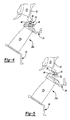
- Figure 4 is an expanded sectional view of a exit stator assembly according to the present invention; and
- Figure 5 is an expanded sectional view of another a stator assembly according to the present invention.
-
- Figure 1 illustrates a general schematic sectional view of a
gas turbine engine 10. Thegas turbine engine 10 is defined about an engine centerline A about which the various engine sections rotate. Generally, theengine 10 includes afan section 12, a low pressure compressor section (LPC) 14, a high pressure compressor section (HPC) 16, acombustor section 18, a highpressure turbine section 20 and a lowpressure turbine section 22. It should be understood that although a particular arrangement is disclosed in the illustrated embodiment, other arrangements will benefit from the instant invention including gas turbines used for electrical power generation and for aircraft. - Referring to Figure 2, the low
pressure compressor section 14 includes alternating rows of rotary airfoils or blades 24 and static airfoils orvanes 26. Onevane assembly 26 is a low-pressure compressor (LPC)exit stator assembly 26a also referred to as "4th" stage. It should be understood that although a particular vane is illustrated in the disclosed embodiment, any vane will benefit from the present invention. - The LPC
exit stator assembly 26a is mounted between an intermediate case structure 28 and ableed duct structure 30 of theengine 10. Thebleed duct structure 30 forms acore compartment 32 and ableed duct 33. - The low pressure compressor
exit stator assembly 26a provides a flow transition passage for high temperature and pressure engine core airflow which exits theLPC 14, travels through atransition duct 35 formed by the intermediate case structure 28 and into theHPC 16. - The LPC
exit stator assembly 26a includes a multiple ofvanes 26s mounted between a full hoopouter shroud 34 and an inner shroud 36 (also illustrated from the front in Figure 3). Thevanes 26s are attached between the full hoopouter shroud 34 and aninner shroud 36. It should be understood that the term full hoop is defined herein as an uninterrupted member such that the vanes do not pass through apertures formed therethrough as in conventional stator assemblies. - The
outer shroud 34 creates a flowpath boundary between theLPC 14 and the intermediatecase core compartment 32. The interface between the low pressure compressorexit stator assembly 26a and thebleed duct 33 may potentially be a leakage path which requires positive sealing to prevent loss of air and engine performance. - The full hoop
outer shroud 34 provides a pressure vessel for the LPCexit stator assembly 26a. Theouter shroud 34 is preferably manufactured of aluminum and theinner shroud 36 is preferably manufactured of titanium. Titanium and aluminum have different thermal growths and the dimensional changes that result from temperature excursions during operation are absorbed at theouter shroud 34 to bleedduct 30 interface. A seal 38 (Figure 4) preferably accommodates the thermal mismatch. Theseal 38 is preferably a high deflection capability seal such as an "Omni Seal" manufactured by Saint-Gobain of Garden Grove, California which absorbs the thermal induced deflections and provides sealing with minimal wear to theadjacent structures - The
outer shroud 34 is supported against the intermediate case structure 28 with abayonet fastener 40. Theinner shroud 36 is mounted to the intermediate case structure 28 with a fastener 42 such as a bolt. Theseal 38 is located between theouter shroud 34 and the bleed duct structure 30 (also illustrated in Figure 4) to accommodate differential movement therebetween. - Referring to Figure 4, the LPC
exit stator 38 is retained through aassembly 26a sealretainer 44 and a threadedfastener 46 arrangement. The threadedfastener 46 is threaded into theouter shroud 34 such that the seal is trapped between theretainer 44 and theouter shroud 34. The fastener arrangement permits maintenance and replacement of the seal. Theseal 38 is of a generally "U" or "V" shape such that the open end thereof is preferably engaged with alip 48 formed into theouter shroud 34. - Referring to Figure 5, the
seal 38 is alternatively retained through a rivetedretainer ring 50 which is located through the outer shroud 34'. The outer shroud 34' provides aledge 52 through which the rivetedretainer ring 50 is received to retain theseal 38 between the rivetedretainer ring 50 and thelip 48. - It should be understood that relative positional terms such as "forward," "aft," "upper," "lower," "above," "below," and the like are with reference to the normal operational attitude of the vehicle and should not be considered otherwise limiting.
- It should be understood that although a particular component arrangement is disclosed in the illustrated embodiment, other arrangements will benefit from the instant invention.
- The foregoing description is exemplary rather than defined by the limitations within. Many modifications and variations of the present invention are possible in light of the above teachings. The preferred embodiments of this invention have been disclosed, however, one of ordinary skill in the art would recognize that certain modifications would come within the scope of this invention. It is, therefore, to be understood that within the scope of the appended claims, the invention may be practiced otherwise than as specifically described. For that reason the following claims should be studied to determine the true scope and content of this invention.
Claims (15)
- A stator assembly comprising:an outer shroud (34);an inner shroud (36);a multiple of vanes (26) mounted between said outer shroud (34) and said inner shroud (38); anda seal (38) mounted to said outer shroud (34).
- The stator assembly as recited in claim 1, wherein said outer shroud (34) comprises a full-hoop construction.
- The stator assembly as recited in claim 1, wherein said outer shroud (34) is uninterrupted.
- The stator assembly as recited in any preceding claim, wherein said outer shroud (34) is manufactured of aluminum.
- The stator assembly as recited in any preceding claim, wherein said inner shroud (36) is manufactured of titanium.
- The stator assembly as recited in any preceding claim, wherein said outer shroud (34) is mounted to an intermediate case structure (28) of a gas turbine engine.
- The stator assembly as recited in any preceding claim, wherein said multiple of vanes (26) are located upstream of a transition duct (35) between a low pressure compressor section (14) and a high pressure compressor section (16) of a gas turbine engine (10).
- The stator assembly as recited in any preceding claim, wherein said seal (38) is located about an outer diameter of said outer shroud (34).
- The stator assembly as recited in claim 8, further comprising a retainer (44; 50) which traps said seal (38) between a retainer and said outer shroud (34).
- The stator assembly as recited in any preceding claim, further comprising a rivet (50) which traps said seal (38) upon a lip (48) which extends from said outer shroud (34).
- A gas turbine engine (10) comprising:an intermediate case structure (28);a bleed duct structure (30);an outer shroud (34) mounted to said intermediate case structure (28);an inner shroud (36) mounted to said intermediate case (28);a multiple of vanes (26) mounted between said outer shroud (34) and said inner shroud (36) ; anda seal (38) mounted to said outer shroud (34), said seal (38) engaged with said bleed duct structure (30).
- The gas turbine engine as recited in claim 11, wherein said outer shroud (34) comprises a full-hoop construction.
- The gas turbine engine as recited in claim 11, wherein said outer shroud (34) is uninterrupted.
- The gas turbine engine as recited in claim 11, 12 or 13, wherein said seal (38) seals a compartment within said bleed duct structure (30).
- The gas turbine engine as recited in any of claims 11 to 14, wherein said multiple of vanes (21) are located upstream of a transition duct (35) between a low pressure compressor section (14) and a high pressure compressor section (16) of the gas turbine engine (10).
Applications Claiming Priority (2)
| Application Number | Priority Date | Filing Date | Title |
|---|---|---|---|
| US742725 | 1996-11-01 | ||
| US10/742,725 US7025563B2 (en) | 2003-12-19 | 2003-12-19 | Stator vane assembly for a gas turbine engine |
Publications (3)
| Publication Number | Publication Date |
|---|---|
| EP1544415A2 true EP1544415A2 (en) | 2005-06-22 |
| EP1544415A3 EP1544415A3 (en) | 2008-11-12 |
| EP1544415B1 EP1544415B1 (en) | 2012-12-12 |
Family
ID=34523259
Family Applications (1)
| Application Number | Title | Priority Date | Filing Date |
|---|---|---|---|
| EP04257870A Expired - Lifetime EP1544415B1 (en) | 2003-12-19 | 2004-12-16 | Stator vane assembly for a gas turbine engine |
Country Status (6)
| Country | Link |
|---|---|
| US (1) | US7025563B2 (en) |
| EP (1) | EP1544415B1 (en) |
| JP (1) | JP4095060B2 (en) |
| KR (1) | KR100706723B1 (en) |
| CN (1) | CN1648417A (en) |
| IL (1) | IL165844A0 (en) |
Cited By (7)
| Publication number | Priority date | Publication date | Assignee | Title |
|---|---|---|---|---|
| RU2433312C2 (en) * | 2005-12-21 | 2011-11-10 | Дженерал Электрик Компани | Turbofan engine with compact system of air takeoff from booster compressor |
| EP2540983A2 (en) * | 2011-06-29 | 2013-01-02 | United Technologies Corporation | Radial spline arrangement for LPT vane clusters |
| EP2233703A3 (en) * | 2009-03-26 | 2013-05-15 | United Technologies Corporation | Gas turbine engine with 2.5 bleed duct core case section |
| FR2989722A1 (en) * | 2012-04-23 | 2013-10-25 | Snecma | Turbine stage for use in e.g. turbojet engine, of aircraft, has distributor comprising radial blades whose radial external ends are secured to annular crown, where crown is connected to casing surrounding distributor by annular unit |
| US9447693B2 (en) | 2012-07-30 | 2016-09-20 | United Technologies Corporation | Compliant assembly |
| US9631517B2 (en) | 2012-12-29 | 2017-04-25 | United Technologies Corporation | Multi-piece fairing for monolithic turbine exhaust case |
| US9909503B2 (en) | 2012-09-26 | 2018-03-06 | United Technologies Corporation | Gas turbine engine including vane structure and seal to control fluid leakage |
Families Citing this family (44)
| Publication number | Priority date | Publication date | Assignee | Title |
|---|---|---|---|---|
| SG143087A1 (en) * | 2006-11-21 | 2008-06-27 | Turbine Overhaul Services Pte | Laser fillet welding |
| US20080189946A1 (en) | 2007-02-14 | 2008-08-14 | United Technologies Corporation One Financial Plaz | Dimensional restoration of stator inner shrouds |
| US9643286B2 (en) * | 2007-04-05 | 2017-05-09 | United Technologies Corporation | Method of repairing a turbine engine component |
| US7900461B2 (en) * | 2007-05-31 | 2011-03-08 | Rolls-Royce Corporation | Combustor liner support and seal assembly |
| US8313289B2 (en) * | 2007-12-07 | 2012-11-20 | United Technologies Corp. | Gas turbine engine systems involving rotor bayonet coverplates and tools for installing such coverplates |
| EP2075416B1 (en) * | 2007-12-27 | 2011-05-18 | Techspace Aero | Method for manufacturing a turboshaft engine element and device obtained using same |
| US8162605B2 (en) * | 2008-01-14 | 2012-04-24 | United Technologies Corporation | Gas turbine engine case |
| US9322285B2 (en) * | 2008-02-20 | 2016-04-26 | United Technologies Corporation | Large fillet airfoil with fanned cooling hole array |
| US8075259B2 (en) * | 2009-02-13 | 2011-12-13 | United Technologies Corporation | Turbine vane airfoil with turning flow and axial/circumferential trailing edge configuration |
| US9587645B2 (en) | 2010-09-30 | 2017-03-07 | Pratt & Whitney Canada Corp. | Airfoil blade |
| US9429029B2 (en) | 2010-09-30 | 2016-08-30 | Pratt & Whitney Canada Corp. | Gas turbine blade and method of protecting same |
| EP2622192A2 (en) * | 2010-09-30 | 2013-08-07 | General Electric Company | Aircraft engine systems and methods for operating same |
| US9291064B2 (en) | 2012-01-31 | 2016-03-22 | United Technologies Corporation | Anti-icing core inlet stator assembly for a gas turbine engine |
| US9427835B2 (en) | 2012-02-29 | 2016-08-30 | Pratt & Whitney Canada Corp. | Nano-metal coated vane component for gas turbine engines and method of manufacturing same |
| US9045985B2 (en) | 2012-05-31 | 2015-06-02 | United Technologies Corporation | Stator vane bumper ring |
| US9394915B2 (en) | 2012-06-04 | 2016-07-19 | United Technologies Corporation | Seal land for static structure of a gas turbine engine |
| US9322337B2 (en) | 2012-06-20 | 2016-04-26 | United Technologies Corporation | Aerodynamic intercompressor bleed ports |
| US9062603B2 (en) | 2012-06-20 | 2015-06-23 | United Technologies Corporation | Four bar drive mechanism for bleed system |
| US20130343883A1 (en) | 2012-06-20 | 2013-12-26 | Ryan Edward LeBlanc | Two-piece duct assembly |
| US9091209B2 (en) | 2012-06-20 | 2015-07-28 | United Technologies Corporation | Four bar bracket |
| US9200530B2 (en) | 2012-07-20 | 2015-12-01 | United Technologies Corporation | Radial position control of case supported structure |
| US9188062B2 (en) | 2012-08-30 | 2015-11-17 | Mitsubishi Hitachi Power Systems, Ltd. | Gas turbine |
| US10982551B1 (en) | 2012-09-14 | 2021-04-20 | Raytheon Technologies Corporation | Turbomachine blade |
| US9366149B2 (en) | 2012-09-21 | 2016-06-14 | United Technologies Corporation | Multi-stage high pressure compressor case |
| US9297312B2 (en) * | 2012-12-29 | 2016-03-29 | United Technologies Corporation | Circumferentially retained fairing |
| CA2903738A1 (en) | 2013-03-07 | 2014-09-12 | Rolls-Royce Canada, Ltd. | Gas turbine engine comprising an outboard insertion system of vanes and corresponding assembling method |
| US20150267610A1 (en) * | 2013-03-13 | 2015-09-24 | United Technologies Corporation | Turbine enigne including balanced low pressure stage count |
| US20150013301A1 (en) * | 2013-03-13 | 2015-01-15 | United Technologies Corporation | Turbine engine including balanced low pressure stage count |
| US10612469B2 (en) | 2013-08-05 | 2020-04-07 | United Technologies Corporation | Diffuser case mixing chamber for a turbine engine |
| US9850771B2 (en) | 2014-02-07 | 2017-12-26 | United Technologies Corporation | Gas turbine engine sealing arrangement |
| US10316749B2 (en) | 2014-10-20 | 2019-06-11 | United Technologies Corporation | Conduit for guiding low pressure compressor inner diameter shroud motion |
| CN104696285B (en) * | 2015-02-12 | 2020-03-17 | 北京华清燃气轮机与煤气化联合循环工程技术有限公司 | Compressor stator blade ring assembly |
| CN105221481B (en) * | 2015-09-18 | 2018-12-11 | 中国航空工业集团公司沈阳发动机设计研究所 | Ring assemblies in a kind of quick detachable stator |
| US10301951B2 (en) | 2016-05-20 | 2019-05-28 | United Technologies Corporation | Turbine vane gusset |
| KR101884551B1 (en) | 2017-01-13 | 2018-08-29 | 주식회사 윈트 | Method of tungsten carbide coating for bushing and tungsten carbide coated bushing |
| US10711613B1 (en) * | 2017-01-17 | 2020-07-14 | Raytheon Technologies Corporation | Gas turbine engine airfoil frequency design |
| US11199096B1 (en) | 2017-01-17 | 2021-12-14 | Raytheon Technologies Corporation | Turbomachine blade |
| US11261737B1 (en) | 2017-01-17 | 2022-03-01 | Raytheon Technologies Corporation | Turbomachine blade |
| US10767488B1 (en) * | 2017-01-17 | 2020-09-08 | Raytheon Technologies Corporation | Gas turbine engine airfoil frequency design |
| US10539153B2 (en) * | 2017-03-14 | 2020-01-21 | General Electric Company | Clipped heat shield assembly |
| US10934943B2 (en) | 2017-04-27 | 2021-03-02 | General Electric Company | Compressor apparatus with bleed slot and supplemental flange |
| US20190234222A1 (en) * | 2018-01-30 | 2019-08-01 | United Technologies Corporation | Angled vane slot |
| CN109128652B (en) * | 2018-10-15 | 2020-07-17 | 中国航发成都发动机有限公司 | Clamp for welding inner ring of static blade ring and blade |
| FR3095830B1 (en) * | 2019-05-10 | 2021-05-07 | Safran Aircraft Engines | TURBOMACHINE MODULE EQUIPPED WITH A SEALING FLAP HOLDING DEVICE |
Citations (4)
| Publication number | Priority date | Publication date | Assignee | Title |
|---|---|---|---|---|
| US2937000A (en) | 1957-08-16 | 1960-05-17 | United Aircraft Corp | Stator units |
| EP0475771A1 (en) | 1990-09-12 | 1992-03-18 | United Technologies Corporation | Compressor case construction |
| FR2695164A1 (en) | 1992-08-26 | 1994-03-04 | Snecma | Turbomachine provided with a device preventing a longitudinal circulation of gas around the stages of straightening vanes. |
| EP1262634A2 (en) | 2001-05-29 | 2002-12-04 | General Electric Company | Integral nozzle and shroud |
Family Cites Families (18)
| Publication number | Priority date | Publication date | Assignee | Title |
|---|---|---|---|---|
| US3042367A (en) * | 1958-07-17 | 1962-07-03 | Gen Motors Corp | Fluid seal |
| US3999883A (en) | 1975-07-02 | 1976-12-28 | General Motors Corporation | Variable turbomachine stator |
| US4157232A (en) | 1977-10-31 | 1979-06-05 | General Electric Company | Turbine shroud support |
| US4896499A (en) * | 1978-10-26 | 1990-01-30 | Rice Ivan G | Compression intercooled gas turbine combined cycle |
| US4868963A (en) * | 1988-01-11 | 1989-09-26 | General Electric Company | Stator vane mounting method and assembly |
| US4953282A (en) * | 1988-01-11 | 1990-09-04 | General Electric Company | Stator vane mounting method and assembly |
| US4897021A (en) * | 1988-06-02 | 1990-01-30 | United Technologies Corporation | Stator vane asssembly for an axial flow rotary machine |
| US5118120A (en) * | 1989-07-10 | 1992-06-02 | General Electric Company | Leaf seals |
| US5320487A (en) * | 1993-01-19 | 1994-06-14 | General Electric Company | Spring clip made of a directionally solidified material for use in a gas turbine engine |
| KR100473751B1 (en) * | 1996-05-20 | 2005-03-16 | 프랫 앤드 휘트니 캐나다 인코포레이티드 | Gas turbine engine shroud seals |
| US5785492A (en) | 1997-03-24 | 1998-07-28 | United Technologies Corporation | Method and apparatus for sealing a gas turbine stator vane assembly |
| DE19745683A1 (en) * | 1997-10-16 | 1999-04-22 | Bmw Rolls Royce Gmbh | Suspension of an annular gas turbine combustion chamber |
| US6139264A (en) * | 1998-12-07 | 2000-10-31 | General Electric Company | Compressor interstage seal |
| US6409472B1 (en) * | 1999-08-09 | 2002-06-25 | United Technologies Corporation | Stator assembly for a rotary machine and clip member for a stator assembly |
| US6347508B1 (en) * | 2000-03-22 | 2002-02-19 | Allison Advanced Development Company | Combustor liner support and seal assembly |
| US6607355B2 (en) * | 2001-10-09 | 2003-08-19 | United Technologies Corporation | Turbine airfoil with enhanced heat transfer |
| FR2831608B1 (en) * | 2001-10-31 | 2004-01-02 | Snecma Moteurs | UNLOADING DEVICE IN A DOUBLE-FLOW REACTOR TURBO |
| US6881032B2 (en) * | 2003-07-08 | 2005-04-19 | United Technologies Corporation | Exit stator mounting |
-
2003
- 2003-12-19 US US10/742,725 patent/US7025563B2/en not_active Expired - Lifetime
-
2004
- 2004-12-03 KR KR1020040100790A patent/KR100706723B1/en not_active Expired - Fee Related
- 2004-12-08 JP JP2004356041A patent/JP4095060B2/en not_active Expired - Fee Related
- 2004-12-16 IL IL16584404A patent/IL165844A0/en unknown
- 2004-12-16 EP EP04257870A patent/EP1544415B1/en not_active Expired - Lifetime
- 2004-12-17 CN CNA2004101049878A patent/CN1648417A/en active Pending
Patent Citations (4)
| Publication number | Priority date | Publication date | Assignee | Title |
|---|---|---|---|---|
| US2937000A (en) | 1957-08-16 | 1960-05-17 | United Aircraft Corp | Stator units |
| EP0475771A1 (en) | 1990-09-12 | 1992-03-18 | United Technologies Corporation | Compressor case construction |
| FR2695164A1 (en) | 1992-08-26 | 1994-03-04 | Snecma | Turbomachine provided with a device preventing a longitudinal circulation of gas around the stages of straightening vanes. |
| EP1262634A2 (en) | 2001-05-29 | 2002-12-04 | General Electric Company | Integral nozzle and shroud |
Cited By (8)
| Publication number | Priority date | Publication date | Assignee | Title |
|---|---|---|---|---|
| RU2433312C2 (en) * | 2005-12-21 | 2011-11-10 | Дженерал Электрик Компани | Turbofan engine with compact system of air takeoff from booster compressor |
| EP1801403A3 (en) * | 2005-12-21 | 2012-09-26 | General Electric Company | Compact booster bleed turbofan |
| EP2233703A3 (en) * | 2009-03-26 | 2013-05-15 | United Technologies Corporation | Gas turbine engine with 2.5 bleed duct core case section |
| EP2540983A2 (en) * | 2011-06-29 | 2013-01-02 | United Technologies Corporation | Radial spline arrangement for LPT vane clusters |
| FR2989722A1 (en) * | 2012-04-23 | 2013-10-25 | Snecma | Turbine stage for use in e.g. turbojet engine, of aircraft, has distributor comprising radial blades whose radial external ends are secured to annular crown, where crown is connected to casing surrounding distributor by annular unit |
| US9447693B2 (en) | 2012-07-30 | 2016-09-20 | United Technologies Corporation | Compliant assembly |
| US9909503B2 (en) | 2012-09-26 | 2018-03-06 | United Technologies Corporation | Gas turbine engine including vane structure and seal to control fluid leakage |
| US9631517B2 (en) | 2012-12-29 | 2017-04-25 | United Technologies Corporation | Multi-piece fairing for monolithic turbine exhaust case |
Also Published As
| Publication number | Publication date |
|---|---|
| IL165844A0 (en) | 2006-01-15 |
| EP1544415A3 (en) | 2008-11-12 |
| JP4095060B2 (en) | 2008-06-04 |
| KR100706723B1 (en) | 2007-04-13 |
| CN1648417A (en) | 2005-08-03 |
| JP2005180428A (en) | 2005-07-07 |
| KR20050062375A (en) | 2005-06-23 |
| US7025563B2 (en) | 2006-04-11 |
| US20050135928A1 (en) | 2005-06-23 |
| EP1544415B1 (en) | 2012-12-12 |
Similar Documents
| Publication | Publication Date | Title |
|---|---|---|
| US7025563B2 (en) | Stator vane assembly for a gas turbine engine | |
| CN109838281B (en) | Shrouds for Gas Turbine Engines | |
| US8007229B2 (en) | Variable area turbine vane arrangement | |
| EP2261467B1 (en) | Inner diameter shroud assembly for variable inlet guide vane structure in a gas turbine engine | |
| US6409472B1 (en) | Stator assembly for a rotary machine and clip member for a stator assembly | |
| EP2093384B2 (en) | Filter system for blade outer air seal | |
| EP2159398B1 (en) | Separation-resistant inlet duct for mid-turbine frames | |
| EP1965031A2 (en) | Turbine engine shroud segment, featherseal for a shroud segment and corresponding assembly | |
| EP3187687B1 (en) | Midspan shrouded turbine rotor blades | |
| EP2540980A2 (en) | Damper for an integrally bladed rotor | |
| EP3653843B1 (en) | Air seal interface with forward engagement features and active clearance control for a gas turbine engine | |
| US8092148B2 (en) | Gas turbine having a peripheral ring segment including a recirculation channel | |
| EP1924758B1 (en) | Vane assembly with outer grommets | |
| US11231043B2 (en) | Gas turbine engine with ultra high pressure compressor | |
| EP3486496B1 (en) | Fan for gas turbine engines having mid-span shroud | |
| EP1132576A2 (en) | Methods and apparatus for minimizing thermal gradients within turbine shrouds | |
| US10036269B2 (en) | Leaf seal reach over spring with retention mechanism | |
| CN114483208B (en) | Seal assembly for a gas turbine engine having a leaf seal | |
| US20190316485A1 (en) | Blade outer air seal cooling fin | |
| US12031442B2 (en) | Turbine engine with a floating interstage seal | |
| EP3851634B1 (en) | Seal element for sealing a joint between a rotor blade and a rotor disk of a turbine engine | |
| US20250163827A1 (en) | Cyclonic separator for seal support | |
| CN112539087B (en) | Turbine Snap in Spring Seal |
Legal Events
| Date | Code | Title | Description |
|---|---|---|---|
| PUAI | Public reference made under article 153(3) epc to a published international application that has entered the european phase |
Free format text: ORIGINAL CODE: 0009012 |
|
| AK | Designated contracting states |
Kind code of ref document: A2 Designated state(s): AT BE BG CH CY CZ DE DK EE ES FI FR GB GR HU IE IS IT LI LT LU MC NL PL PT RO SE SI SK TR |
|
| AX | Request for extension of the european patent |
Extension state: AL BA HR LV MK YU |
|
| PUAL | Search report despatched |
Free format text: ORIGINAL CODE: 0009013 |
|
| AK | Designated contracting states |
Kind code of ref document: A3 Designated state(s): AT BE BG CH CY CZ DE DK EE ES FI FR GB GR HU IE IS IT LI LT LU MC NL PL PT RO SE SI SK TR |
|
| AX | Request for extension of the european patent |
Extension state: AL BA HR LV MK YU |
|
| RIC1 | Information provided on ipc code assigned before grant |
Ipc: F04D 29/54 20060101ALI20081010BHEP Ipc: F01D 25/24 20060101ALI20081010BHEP Ipc: F04D 29/64 20060101ALI20081010BHEP Ipc: F01D 9/04 20060101ALI20081010BHEP Ipc: F01D 9/02 20060101AFI20050216BHEP |
|
| 17P | Request for examination filed |
Effective date: 20090202 |
|
| AKX | Designation fees paid |
Designated state(s): DE FR GB |
|
| 17Q | First examination report despatched |
Effective date: 20100901 |
|
| REG | Reference to a national code |
Ref country code: DE Ref legal event code: R079 Ref document number: 602004040374 Country of ref document: DE Free format text: PREVIOUS MAIN CLASS: F01D0009020000 Ipc: F02C0009180000 |
|
| RIC1 | Information provided on ipc code assigned before grant |
Ipc: F04D 29/54 20060101ALI20120221BHEP Ipc: F04D 29/64 20060101ALI20120221BHEP Ipc: F01D 25/24 20060101ALI20120221BHEP Ipc: F02C 9/18 20060101AFI20120221BHEP Ipc: F01D 9/04 20060101ALI20120221BHEP |
|
| GRAP | Despatch of communication of intention to grant a patent |
Free format text: ORIGINAL CODE: EPIDOSNIGR1 |
|
| GRAS | Grant fee paid |
Free format text: ORIGINAL CODE: EPIDOSNIGR3 |
|
| GRAA | (expected) grant |
Free format text: ORIGINAL CODE: 0009210 |
|
| AK | Designated contracting states |
Kind code of ref document: B1 Designated state(s): DE FR GB |
|
| REG | Reference to a national code |
Ref country code: GB Ref legal event code: FG4D Ref country code: DE Ref legal event code: R081 Ref document number: 602004040374 Country of ref document: DE Owner name: UNITED TECHNOLOGIES CORP. (N.D.GES.D. STAATES , US Free format text: FORMER OWNER: UNITED TECHNOLOGIES CORP. (N.D.GES.D. STAATES DELAWARE), HARTFORD, CONN., US |
|
| REG | Reference to a national code |
Ref country code: DE Ref legal event code: R096 Ref document number: 602004040374 Country of ref document: DE Effective date: 20130207 |
|
| PLBE | No opposition filed within time limit |
Free format text: ORIGINAL CODE: 0009261 |
|
| STAA | Information on the status of an ep patent application or granted ep patent |
Free format text: STATUS: NO OPPOSITION FILED WITHIN TIME LIMIT |
|
| 26N | No opposition filed |
Effective date: 20130913 |
|
| REG | Reference to a national code |
Ref country code: FR Ref legal event code: ST Effective date: 20131023 |
|
| REG | Reference to a national code |
Ref country code: DE Ref legal event code: R097 Ref document number: 602004040374 Country of ref document: DE Effective date: 20130913 |
|
| PG25 | Lapsed in a contracting state [announced via postgrant information from national office to epo] |
Ref country code: FR Free format text: LAPSE BECAUSE OF NON-PAYMENT OF DUE FEES Effective date: 20130212 |
|
| REG | Reference to a national code |
Ref country code: DE Ref legal event code: R082 Ref document number: 602004040374 Country of ref document: DE Representative=s name: SCHMITT-NILSON SCHRAUD WAIBEL WOHLFROM PATENTA, DE |
|
| REG | Reference to a national code |
Ref country code: DE Ref legal event code: R082 Ref document number: 602004040374 Country of ref document: DE Representative=s name: SCHMITT-NILSON SCHRAUD WAIBEL WOHLFROM PATENTA, DE Ref country code: DE Ref legal event code: R081 Ref document number: 602004040374 Country of ref document: DE Owner name: UNITED TECHNOLOGIES CORP. (N.D.GES.D. STAATES , US Free format text: FORMER OWNER: UNITED TECHNOLOGIES CORPORATION, HARTFORD, CONN., US |
|
| PGFP | Annual fee paid to national office [announced via postgrant information from national office to epo] |
Ref country code: DE Payment date: 20191119 Year of fee payment: 16 |
|
| PGFP | Annual fee paid to national office [announced via postgrant information from national office to epo] |
Ref country code: GB Payment date: 20201123 Year of fee payment: 17 |
|
| REG | Reference to a national code |
Ref country code: DE Ref legal event code: R119 Ref document number: 602004040374 Country of ref document: DE |
|
| PG25 | Lapsed in a contracting state [announced via postgrant information from national office to epo] |
Ref country code: DE Free format text: LAPSE BECAUSE OF NON-PAYMENT OF DUE FEES Effective date: 20210701 |
|
| GBPC | Gb: european patent ceased through non-payment of renewal fee |
Effective date: 20211216 |
|
| PG25 | Lapsed in a contracting state [announced via postgrant information from national office to epo] |
Ref country code: GB Free format text: LAPSE BECAUSE OF NON-PAYMENT OF DUE FEES Effective date: 20211216 |