EP1544134A1 - Förderer mit Trägerelementen, insbesondere zum Sammeln von Produkteinheiten - Google Patents
Förderer mit Trägerelementen, insbesondere zum Sammeln von Produkteinheiten Download PDFInfo
- Publication number
- EP1544134A1 EP1544134A1 EP03104829A EP03104829A EP1544134A1 EP 1544134 A1 EP1544134 A1 EP 1544134A1 EP 03104829 A EP03104829 A EP 03104829A EP 03104829 A EP03104829 A EP 03104829A EP 1544134 A1 EP1544134 A1 EP 1544134A1
- Authority
- EP
- European Patent Office
- Prior art keywords
- conveyor
- buckets
- bucket
- machine
- station
- Prior art date
- Legal status (The legal status is an assumption and is not a legal conclusion. Google has not performed a legal analysis and makes no representation as to the accuracy of the status listed.)
- Withdrawn
Links
- 238000011144 upstream manufacturing Methods 0.000 claims abstract description 62
- 230000000284 resting effect Effects 0.000 claims abstract description 7
- 230000002441 reversible effect Effects 0.000 claims description 4
- 238000007599 discharging Methods 0.000 claims description 2
- 238000004140 cleaning Methods 0.000 description 5
- 230000032258 transport Effects 0.000 description 5
- XEEYBQQBJWHFJM-UHFFFAOYSA-N Iron Chemical compound [Fe] XEEYBQQBJWHFJM-UHFFFAOYSA-N 0.000 description 4
- 238000004806 packaging method and process Methods 0.000 description 3
- 229910000831 Steel Inorganic materials 0.000 description 2
- 230000015572 biosynthetic process Effects 0.000 description 2
- 238000005755 formation reaction Methods 0.000 description 2
- 229910052742 iron Inorganic materials 0.000 description 2
- 239000010959 steel Substances 0.000 description 2
- 238000009825 accumulation Methods 0.000 description 1
- 239000000463 material Substances 0.000 description 1
Images


Classifications
-
- B—PERFORMING OPERATIONS; TRANSPORTING
- B65—CONVEYING; PACKING; STORING; HANDLING THIN OR FILAMENTARY MATERIAL
- B65G—TRANSPORT OR STORAGE DEVICES, e.g. CONVEYORS FOR LOADING OR TIPPING, SHOP CONVEYOR SYSTEMS OR PNEUMATIC TUBE CONVEYORS
- B65G35/00—Mechanical conveyors not otherwise provided for
- B65G35/06—Mechanical conveyors not otherwise provided for comprising a load-carrier moving along a path, e.g. a closed path, and adapted to be engaged by any one of a series of traction elements spaced along the path
-
- B—PERFORMING OPERATIONS; TRANSPORTING
- B65—CONVEYING; PACKING; STORING; HANDLING THIN OR FILAMENTARY MATERIAL
- B65G—TRANSPORT OR STORAGE DEVICES, e.g. CONVEYORS FOR LOADING OR TIPPING, SHOP CONVEYOR SYSTEMS OR PNEUMATIC TUBE CONVEYORS
- B65G17/00—Conveyors having an endless traction element, e.g. a chain, transmitting movement to a continuous or substantially-continuous load-carrying surface or to a series of individual load-carriers; Endless-chain conveyors in which the chains form the load-carrying surface
- B65G17/002—Conveyors having an endless traction element, e.g. a chain, transmitting movement to a continuous or substantially-continuous load-carrying surface or to a series of individual load-carriers; Endless-chain conveyors in which the chains form the load-carrying surface comprising load carriers resting on the traction element
-
- B—PERFORMING OPERATIONS; TRANSPORTING
- B65—CONVEYING; PACKING; STORING; HANDLING THIN OR FILAMENTARY MATERIAL
- B65G—TRANSPORT OR STORAGE DEVICES, e.g. CONVEYORS FOR LOADING OR TIPPING, SHOP CONVEYOR SYSTEMS OR PNEUMATIC TUBE CONVEYORS
- B65G2201/00—Indexing codes relating to handling devices, e.g. conveyors, characterised by the type of product or load being conveyed or handled
- B65G2201/02—Articles
- B65G2201/0235—Containers
- B65G2201/0261—Puck as article support
Definitions
- the present invention relates to a bucket conveying machine comprising "free" buckets for handling product units.
- a "free" bucket conveying machine a plurality of buckets which are used for receiving product units rest freely on a conveyor for said buckets such that they can be easily removed and exchanged with other buckets, for example differently sized buckets.
- the present invention also provides a device for controlling the position of buckets, for example at a product unit loading station, or at a bucket accumulating station. Further, the present invention provides a machine for collating product units.
- EP 1094098 A1 discloses a bucket conveying machine comprising a chain conveyor, and a plurality of buckets for handling product units which are adapted to be supported freely and transported by the chain conveyor.
- Said chain conveyor comprises an endless chain that is arranged to circulate around an endless path in a substantially horizontal plane.
- the chain is provided with formations adapted to engage with corresponding formations formed on each bucket. Since each bucket is freely supported by the chain conveyor, it is easy to remove the buckets for cleaning, or for exchange with differently sized buckets.
- the fact that the chain must move in a substantially horizontal plane is limiting, and has the result that the chain conveyor occupies a large "footprint".
- Conveyors which operate in a substantially vertical plane are generally preferred to horizontal conveyors, because they occupy a smaller floor area.
- Bucket conveyors which are adapted to operate in the vertical mode are disclosed by WO 97/11014 A1 (Langenpac NV) and EP 0316990 A1 (Vortex Systems SrL), but in these conveyors the buckets are mounted on a conveyor such that they can not fall off, and as a result they are not easily removed for cleaning or exchange with buckets of a different size.
- Another object of the present invention is to provide a "free" bucket conveyor which is arranged to operate in the vertical mode, i.e. the conveyor comprises an endless belt or chain arranged for rotation in a substantially vertical plane around a closed path, whilst the bucket are freely supported by a conveyor such that they can easily be removed for cleaning or exchange with buckets of a different size.
- Another object of the present invention is to provide a device for controlling the position of buckets at a product unit loading station or a bucket accumulating station, which is adapted for use with "free" buckets.
- Yet another object of the present invention is to provide a product collating machine which incorporates the bucket conveying machine of the present invention.
- a bucket conveying machine comprising:
- the bucket conveying machine of the present invention therefore comprises a first bucket conveyor for transporting a plurality of buckets resting freely thereon from the first position to the second position. At the second position, the buckets are removed from the first conveyor by the first transfer means, and transferred to the second return conveyor, which is adapted to return the buckets from said second position of the first conveyor to the first position thereof.
- a second transfer means is provided for transferring buckets from the second conveyor to the first conveyor at said first position.
- said first conveyor comprises an endless belt which is arranged for rotation in a substantially vertical plane around a closed path, said belt having an upper run extending between said first and second positions.
- the bucket conveying machine of the present invention is therefore adapted to operate in a vertical mode, thereby occupying a minimal floor area.
- the second return conveyor also comprises an endless belt arranged for rotation in a substantially vertical plane around a closed path, such that the second return conveyor too operates in the vertical mode.
- the second return conveyor may be positioned in vertical alignment with the first conveyor so as to minimise the floor area occupied by the machine of the present invention.
- the second return conveyor may be disposed beneath the first bucket conveyor.
- said first position may be disposed at or towards a first end of the first conveyor.
- Said second position may be disposed at or towards a second end of the first conveyor.
- Said first end may be an upstream end in normal use, and said second end may be a downstream end.
- each bucket may comprise an element of magnetisable material, for example a piece of iron or steel
- the first transfer means may comprise a first magnetic transfer wheel which is adapted to pick up the buckets at the downstream end of the first conveyor, and deliver the buckets to the return conveyor.
- Said second transfer means may comprise a second magnetic transfer wheel which is adapted to pick up buckets from the second conveyor and deliver the buckets to the upstream end of the first conveyor.
- the first or second magnetic transfer wheel may comprise a plurality of magnetic elements, for example permanent magnets or electromagnets, which are adapted to cooperate with the magnetisable elements on the buckets to attach the buckets to the first or second magnetic transfer wheel for transfer between the first and second conveyors.
- magnetic elements for example permanent magnets or electromagnets
- the endless belt of the first conveyor may comprise a lower run, and said return conveyor may be disposed beneath said lower run, such that the buckets on the lower conveyor remain closely adjacent, or in contact with, the belt of the first conveyor.
- means may be provided for adjusting the spacing between the lower run of the belt of the first conveyor, and the second conveyor to accommodate buckets of different sizes.
- means may be provided for selectively moving the second return conveyor so as to decouple it from one of said first and second transfer wheels, whilst remaining coupled with the other transfer wheel. In this way, the first and second conveyors may be operated to discharge buckets from the machine.
- said return conveyor may be selectively moveable between a first coupled position in which the return conveyor is arranged to supply buckets to the second transfer means to return them to the first conveyor, and a second decoupled position in which the second conveyor is arranged to discharge buckets from the machine.
- Said drive means may comprise a reversible drive associated with the second conveyor, said reversible drive being operable in a first direction for discharging buckets from the machine, and in a second opposite direction for loading buckets onto the second conveyor.
- Selectively operable positioning means may be provided for automatically positioning the second conveyor in the first or second positions.
- a take-off conveyor may be provided for receiving buckets from the return conveyor in the de-coupled position.
- the bucket conveying machine of the present invention can easily be operated with buckets of different sizes, and the buckets can easily be removed from the machine for cleaning or exchange.
- a device for controlling the position of one or more buckets on a conveyor particularly at a product unit loading station, or a bucket accumulating station, of the conveyor, said device comprising;
- said second conveyor may comprise an endless belt which is positioned juxtaposed the first conveyor, said endless belt being arranged for rotation in a substantially vertical plane around a closed path, and having an upper run extending between first and second ends thereof.
- the upper run of the endless belt is preferably positioned above the level of the first conveyor, such that buckets transported from the first conveyor onto the second conveyor are lifted up from the first conveyor, out of contact with the first conveyor.
- Means may be provided for guiding the endless belt of the second conveyor for guiding buckets from the first conveyor onto the second conveyor, and up to the level of the upper conveying run thereof.
- the second conveyor may form a ramp up proximate the first end of the upper conveying run.
- means may also be provided for guiding the endless belt of the second conveyor to guide buckets from the upper conveying run of the endless belt of the second conveyor back down onto the first conveyor for onward transport thereon.
- the belt of the second conveyor may be guided to form a ramp down at the second end thereof.
- said second conveyor may be dimensioned to accommodate a predetermined number of successive buckets thereon.
- the upper run of the second conveyor may be adapted to accommodate one or more buckets, for example two to six, typically, two, three or four buckets.
- the second conveyor may comprise magnetic means adapted to attract magnetically buckets which are provided with cooperating magnetic or magnetisable means, whereby the buckets are held firmly in contact with the second conveyor when disposed thereon.
- each bucket may comprise a magnetisable element such, for example, as a piece or shape of iron or steel
- the second conveyor may comprise a magnetic element positioned beneath the upper run of the endless belt of the second conveyor for attracting the magnetisable means in each bucket.
- the magnetic element of the second conveyor may comprise a permanent magnet, for example a ferromagnet, or an electromagnet.
- assisting means may be provided proximate the first end of second conveyor for assisting the buckets onto the second conveyor.
- said assisting means may comprise one or more assisting magnets, which may be permanent magnets or electromagnets.
- Said assisting magnet or magnets may be positioned generally above the first and second conveyors, and may be adapted to attract the buckets, such that proximate the first upstream end of the second conveyor, each bucket is drawn upwardly to facilitate its transfer onto the second conveyor.
- one or more air nozzles may be suitably positioned to direct the buckets onto the second conveyor.
- the machine for collating product units in accordance with the present invention comprises a bucket conveying machine in accordance with the present invention.
- At least one of said product loading station and said accumulating station may comprise a device for controlling the position of the buckets in accordance with the present invention.
- said product loading station or the accumulating station may be adapted to accelerate said buckets or groups of buckets to at least the speed of the first conveyor.
- said unloading station may comprise a lug conveyor juxtaposed said first conveyor, said lug conveyor comprising one or more spaced abutments adapted to engage said groups of buckets, and servo drive means for controlling movement of said lug conveyor to control the movement of said groups.
- the lug conveyor may be adapted to run more slowly than the first conveyor.
- the lug conveyor may be adapted to run faster than the first conveyor.
- Means may be provided for detecting buckets at each of said loading and accumulating stations.
- Means may be provided for detecting a pre-determined maximum number of buckets at said loading station.
- the machine may further comprise selectively operable bucket holding means adapted to retain buckets on the second conveyor, and controlling means for automatically actuating said holding means if the maximum number of buckets is detected at said loading station.
- the machine further comprises a plurality of different sets of buckets, the buckets of each set being suitable for use with a different respective size or shape of product unit.
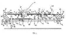
- a machine for collating product units in accordance with the present invention comprises a first upper conveyor 10 comprising an endless belt 12 that is supported for rotation in a substantially vertical plane so as to define a first, substantially horizontal upper conveying run 14, and a second lower return run 16.
- the first upper conveyor 10 has a first upstream end 20 and a second downstream end 22.
- a first upstream reversing wheel 24 is rotatably mounted to the machine juxtaposed the upstream end 20 of the first upper conveyor 10.
- a second downstream reversing wheel 26 is mounted to the machine juxtaposed the second downstream end 22 of the first conveyor 10.
- Each of said reversing wheels 24, 26 comprises an inner cylindrical drum portion 30 and two spaced, opposing outer disk portions 32, having a diameter greater then that of the drum portion 30.
- the inner drum portion 30 and outer disk portions 32 are fixedly secured together for rotation about an axis 34 as a single unit.
- the width of the drum portion 30 in the axial direction which extends substantially orthogonally to the longitudinal direction of the upper conveyor 10, is approximately equal to the width of the belt 12.
- each reversing wheel 24, 26 is approximately equal to the spacing between the upper and lower runs 14, 16 of the belt 12, and the reversing wheels 24, 26 and guide rollers are positioned such that the disk portions 32 of the wheels 24, 26 are disposed closely adjacent a respective lateral side of the belt 12.
- Each disk portion 32 of each reversing wheel 24, 26 comprises a substantially cylindrical outer surface 36 which is equipped with a plurality circumferentially spaced magnetic elements 40.
- Each of said magnetic elements 40 may comprise a permanent magnet or an electromagnet, with suitable means for energising the coil of each electromagnetic in use being provided.
- the upper run 14 of the belt 12 is adapted to support a plurality of buckets 50 thereon, and to convey said buckets 50 from the upstream end 20 of the first conveyor 10 to the downstream end 22 thereof. (The buckets are omitted in FIG. 2 for clarity).
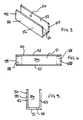
- Each bucket 50 comprises a rectangular base 51, and upstanding front and back walls 52, 53.
- the underside of each bucket 50 may be provided with a non-smooth surface which is adapted to provide sufficient fiction with the conveying surface of the belt 12 to allow the buckets 50, which rest freely on the belt 12, to be transported thereon.
- each bucket 50 defines an interior cavity 54 that is adapted to receive one or more product units as described in more detail below.
- the bucket 50 has two open sides 55 which are adapted to allow product units to be inserted into, and removed from, the cavity 54.
- the bucket is adapted to be placed on the belt 12 of the upper conveyor 10 with its front and back walls 52, 53 disposed fore-and-aft, and the width of the bucket 50 between said open sides 55 is greater than the width of the belt 12, and is somewhat greater than the spacing between the disk portions 32 of each of the reversing wheels 24, 26.
- Juxtaposed each open side 55, the base 51 of the bucket 50 incorporates a respective magnetisable element 58 as shown in FIG. 4, which magnetisable elements 58 are adapted to engage the magnetic elements 40 provided on the reversing wheels 24, 26 in the manner described in more detail below.
- One of the said reversing wheels 24, 26 is operatively connected to a selectively operable electric motor for driving the belt 12 around the closed path defined by the upper and lower runs 14, 16, the drum portions 30 of the reversing wheels 24, 26 and the guide rollers.
- the buckets 50 are adapted to rest freely on the belt 12.
- a second lower conveyor 60 is disposed directly beneath the first upper conveyor 10.
- the said lower conveyor 60 comprises an endless belt 62 that is supported at upstream and downstream ends 70, 72 respectively by two reversing wheels 74, 76 respectively, the terms “upstream” and “downstream” in the context of the lower conveyor 60 referring to the normal conveying direction in use of the upper conveyor 10.
- One of said reversing wheels 74, 76 is operatively connected to a selectively operable drive motor (not shown) for driving the belt 62 about a closed path defined by the two reversing wheels 74, 76.
- the upstream reversing wheel 74 of the second lower conveyor 60 is disposed beneath the first upstream reversing wheel 24 of the first conveyor 10, and similarly the downstream reversing wheel 76 of the second conveyor 60 is disposed beneath the second downstream reversing wheel 26 of the first conveyor 10.
- the belt 62 of the second lower conveyor 60 defines an upper conveying run 64, and a lower return run 66.
- the second lower conveyor 60 is supported by the machine in such a manner that the spacing between the upper conveying run of the belt 62 of the lower conveyor 60 and the lower return run 16 of the belt 12 of the upper conveyor 10 can be adjusted to accommodate differently sized buckets as described below.
- the second lower conveyor 60 is pivoted at its second downstream end 72, and a selectively operable mechanism 78 is provided for raising and lowering the upstream end 70 of the second lower conveyor 60 between an operating configuration as shown in solid lines, and a bucket loading/unloading position as shown in phantom lines.
- the upper and lower conveyors 10, 60 define a complete endless circuit for the buckets 50.
- the first upper conveyor 10 By driving the first upper conveyor 10 in the direction of arrow A, and the second lower conveyor 60 in the direction of arrow B, buckets 50, resting freely on the upper conveying run 14 of the belt 12 of the first conveyor 10 are transported from the upstream end 20 of the upper conveyor 10 to the downstream end 22 thereof.
- the width of each bucket 50 between its two open sides 55 is greater than the transverse width of the belt 12 at the first conveyor 10.
- the reversing wheel 26 is thus positioned to pick-up successive buckets 50 as shown in FIG. 1.
- each bucket 50 engages with respective disk portions 32 of the reversing wheel 26 and, in particular, the magnetisable elements 58 provided in the base 51 of the bucket engage with the magnetic elements 40 on the outer surface 36 of the disk portions 32, so that the bucket 50 is securely attached to the reversing wheel 26.
- Each bucket 50 is carried by the reversing wheel 26 at the downstream end 22 of the first conveyor 10 until it engages the lower run 16 of the upper conveyor 10, and the upper conveying run 64 of the second lower conveyor 60. The bucket 50 is then removed from the reversing wheel 26 and is carried by the upper conveying run 64 of the lower conveyor 16 in the direction of arrow B towards the upstream end 20 of the conveyor 10.
- the spacing between the upper conveying run 64 of the lower conveyor 60, and the lower conveying run 16 of the upper conveyor 10 is adjusted to be substantially equal to the height of the buckets 50, so that as the buckets 50 are conveyed by the second conveyor 60, their bases 51 remain closely adjacent, or in contact with, the belt 12 of the upper conveyor 10.
- the buckets 50 are thus returned by the lower conveyor 60 from the downstream end 22 of the first conveyor 10 to the upstream end 20 thereof.
- the reversing wheel 24 is arranged in a similar manner to the reversing wheel 26 at the downstream end 22. Specifically, the reversing wheel 24 of the upstream end 20 is arranged to pick-up buckets 50 from the lower conveyor 60, such that the laterally protruding portions of each bucket 50 engage with the disk portions 32 of the upstream reversing wheel 24, with the magnetisable elements 58 provided in the base of 51 of each bucket 50 engaging with respective magnetic elements 40 provided on the disk portions 32.
- the buckets 50 are then carried successively by the upstream reversing wheel 24 to the upstream end 20 of the upper conveying run 14 of the first conveyor 10, where they are removed from the reversing wheel 24 and re-engaged with the belt 12.
- the product unit collating machine in accordance with the present invention comprises a product loading station 80 at a position on the upper conveying run 14 of the upper conveyor 10, somewhat downstream of the upstream end 20 of the upper conveyor 10.
- a product unit infeed 81 at said loading station 80 is selectively operable to supply a succession of product units 82.
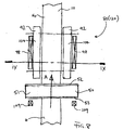
- the loading station 80 comprises a bucket positioning device 90 as shown in FIGS. 6 - 9.
- Said bucket positioning device 90 comprises two spaced, lateral side belts 92, each of which is rotatably supported by an upstream pulley 93, and a downstream pulley 94.
- the upstream pulleys 93 of said two lateral side belts are mounted on a common axle 95 for simultaneous rotation, and similarly, the two downstream pulleys 94 are mounted on a common axle 96.
- the two lateral side belts 92 are therefore interconnected to rotate together at the same speed, and in the same direction.
- the pulleys 93, 94 are positioned just below the level of the upper conveying run 14 of the upper conveyor 10, and each lateral side belt 92 has an upper conveying run 104 and a lower return run 106.
- Suitable guides 99 such, for example, as rollers or low friction rods are positioned with respect to the upstream and downstream pulleys 93, 94, and the upper conveying run 14 of the upper conveyor 10, so as to divert the upper conveying run 104 of each lateral side band 92 above the level of the upper conveying run 14 of the belt 12 of the upper conveyor 10, and to define a ramp up 103 from the upstream pulley 93 to the upper conveying run 104, and a ramp down 105 from the upper conveying run 104 of belt 92 to downstream pulley 94.
- the bucket position controlling device 90 comprises a magnetic bar 98.
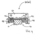
- Each magnetic bar 98 may be positioned beneath the upper run 104 of its respective side belt 92, or to the side of said side belt 92 as shown in FIGS. 7 to 9. The latter position is especially preferred where high power magnets are used to attract buckets 50 supported for the time being on the upper conveying run 104, in order to avoid rubbing of the belts 92 on the magnetic bars 98 which might cause unwanted friction.
- means may be provided for adjusting the spacing of the magnetic bars 98 from their respective upper conveying runs 104, so as to control the effective power of said bars at said upper conveying runs 104.
- the vertical position of each magnetic bar 98 could be adjustable.
- the upstream pulleys 93, or the downstream pulleys 94 of the bucket positioning device 90 are drivably connected to a servo drive 100 via drive belt 102.
- Said servo drive 100 can be selectively operated to control accurately the position of the lateral sides belt 92.
- the lateral side belts 92 of the bucket positioning device 90 are dimensioned to carry a pre-determined number of buckets 50 on the upper conveying run 104.
- the belts 92 are dimensioned to carry three buckets 50, although this number may be altered as required by shorting or lengthening the upper conveying run 104 of each lateral side belt 92.
- the bucket positioning device 90 at the loading station 80 is positioned such that the leading bucket 50 on the upper conveying run 104 in the direction of travel A of the upper conveyor 10 is aligned with the product infeed 81.
- a first bucket detector 110 is disposed vertically above the bucket position controlling device 90 at the loading station 80 to detect the presence of a bucket 50 at the downstream end of the upper conveying run 104 of the lateral side belts 92, in alignment with the product infeed 81.
- Any suitable detector known to those skilled in the art may be employed for this purpose, but, by way of example, the detector may comprise a photocell.
- the photocell 110 may be aligned with the desired position of the front wall 52 of the leading bucket 50.
- the first detector 110 is connected to a suitable computer control system (not shown), which computer control system is also connected to the drive motors of the upper and lower conveyors 10, 60 and the servo drive 100 of the bucket position controlling device 90 at the product loading station 80.
- a second detector 111 is positioned upstream of the loading station 80 to detect the presence of at least one bucket 50 on the belt 12 immediately upstream of the bucket position controlling device 90.
- a third detector 112 is positioned upstream of the second detector 111, and just downstream of the upstream end 20 of the first upper conveyor 10 to detect the presence of a predetermined maximum number of buckets 50 between the upstream end 20 of the upper conveyor 10 and the product loading station 80.
- the product collating machine in accordance with the invention comprises a bucket accumulating station 120.
- Said bucket accumulating station 120 comprises a bucket positioning device 90 of the kind described above for use at the product loading station 80.
- the servo drive 100 of the bucket positioning device 90 at the bucket accumulating station 120 is also connected to the computer control system.
- the bucket accumulating station 120 comprises a first detector 130 that is positioned above the desired position of a leading bucket 50 at the accumulating station 120 in the same manner as the first detector 110 of the product loading station 80, a second detector 131 to detect the presence of a predetermined minimum number of buckets 50 on the belt 12 immediately upstream of the bucket accumulating station 120, and a third detector 132, upstream of the second sensor 131, and somewhat downstream of the product loading station 80, for detecting the presence of a pre-determined maximum buckets 50 intermediate the product loading station 80 and the bucket accumulating station 120.
- the first, second and third detectors, 130, 131, and 132 of the bucket accumulating station 120 are connected to the computer control system.
- the machine of the present invention comprises a product unloading station 140 which is adapted to remove product units from groups comprising a pre-determined number of buckets accumulated at the accumulating station 120 to be received by a different machine 142, for example a packaging or cartonning machine.
- Said unloading station 140 comprises a lug conveyor 144 comprising two spaced, lateral lug belts 145.
- Each lug belt 145 is rotatably supported on a respective upstream roller 146, and a downstream roller 147, such that each lug belt 145 is arranged closely adjacent a respective lateral edge of the belt 12 of the upper conveyor 10 as best shown in FIG. 2.
- the upstream rollers 146 of the two lug belts 145 are mounted on a common axle 148, and the two downstream rollers 147 are mounted on a common axle 149, such that the two lug belts 145 are constrained to rotate together at the same speed, and in the same direction.
- Each lug belt 145 carries a plurality of spaced lugs 150, the spacing of the lugs 150 on each belt 145 being the same, and the two belts 145 being mounted on their respective upstream and downstream rollers 146, 147, such that the lugs 150 on the two lug belts 145 are aligned with one another.
- One of the axles 148, 149 is drivably connected to a servo drive (not shown) for selective operation of the lug conveyor 144.
- the said servo drive is connected to the computer control system, and may be adapted to drive the lug belt 145 either faster or slower than the belt 12 of the first upper conveyor 10, as described in more detail below.
- a bucket loading/unloading conveyor 160 Juxtaposed the upstream end of the second return conveyor 60 is provided a bucket loading/unloading conveyor 160.
- Said bucket loading/unloading conveyor 160 is positioned at the level of the upstream end of the second conveyor 60 in the bucket loading/unloading position as shown in phantom lines in FIG. 1.
- a set of buckets 50 may be loaded onto the machine of the present invention by pivoting the second lower conveyor 60 about its downstream end 72 to the bucket loading/unloading position in which the upstream end 70 of the second lower conveyor 60 is aligned with the bucket loading/unloading conveyor 160.
- the buckets 50 are loaded onto the bucket loading/unloading conveyor 160 in an upside-down orientation (i.e. with their bases 51 uppermost), which conveyor 160 then operated to transport the buckets 50 thereon to the second bucket conveyor 60 which is operated to drive the upper run 64 thereof in the direction of arrow D.
- Said bucket loading/unloading conveyor 160 and said lower return conveyor 60 are operated until all of the buckets 50 are loaded onto the second return layer 60.
- the second return conveyor 60 is operated to move the buckets in the direction of arrow B and the first upper conveyor 10 is operated in the direction of arrow A.
- a bucket 50 reaches the upstream end 70 of the lower conveyor 60 it is picked-up by the upstream reversing wheel 24, and moved to the upstream end 20 of the upper run 14 of the upper conveyor 10 as described above.
- the bucket position controlling the device 90 at the product loading station 80 is halted, so that the buckets 50 accumulate immediately upstream of the product loading station 80.
- a stopping device 68 provided on the second conveyor 60 juxtaposed its upstream end 70 is actuated by means of the computer control system to retain the remaining buckets 50 on the second lower conveyor, so that no buckets 50 can accumulate on the upstream reversing wheel 24.
- the servo drive 100 of the bucket position controlling device 90 at the product loading station 80 is then operated slowly to drive the lateral side belts 92.
- the buckets 50 accumulated upstream of the product loading station are transported onto the bucket position controlling device 90, as the lateral side belts 92 engage with the laterally protruding portions at the sides of the bucket 50.
- Said ramp up 103 guides each bucket 50 in turn upwardly from the surface of the belt 12 on to the upper conveying run 104 of the bucket position controlling device 90. As best seen in FIGS.
- each belt 92 of the bucket position controlling device 90 is disposed above the level of the belt 12, and so buckets 50 picked-up by the bucket controlling device 90 are lifted off the belt 12, such that their positions may be controlled exclusively by the bucket position controlling device 90.
- an air nozzle 108 may optionally be provided to assist movement of the buckets 50 onto the lateral side belts 92 of the bucket position controlling device 90.
- suitably positioned assisting magnets 109 of appropriate power may be employed for this purpose as shown in FIG. 9.
- Such assisting magnets 109 may act to draw the buckets 50 upwardly with respect to the upper conveying run 14 of the main conveyor 10, to assist in moving them onto the side belts 92 of the bucket position controlling device 90.
- bucket position controlling device 90 Since the bucket position controlling device 90 is operated more slowly than the first upper conveyor 10, successive buckets 50 remain contiguous with one another as shown in FIGS. 1 and 6 as they are loaded onto to the bucket position controlling device 90.
- the servo motor 100 is operated by the computer control system to halt movement of the belts 92, thus bringing the buckets on the bucket position controlling device 90 to rest.
- the computer control system releases the stopping device 68 to allow more buckets 50 to be transported from the second return conveyor 60 the first conveyor 10 by the upstream reversing wheel 24.
- the product infeed device 81 is operated to deliver a predetermined number of product units 82 to the leading bucket 50 on the bucket position controlling device 90.
- the pre-determined number of product units to be delivered into each bucket 50 may vary according to the particular product units to be handled. But in the embodiment shown in FIG. 1, each bucket receives two product units 82.
- the product units are delivered into the cavity 54 of the bucket 50 via one of its open sides 55 in a manner known to those skilled in the art.
- the servo drive 100 is reactuated to move the buckets 50 on the bucket position controlling device 90 forwardly by the length of one bucket 50.
- the leading bucket is thus delivered back on to the belt 12 of the first upper conveyor 10, where continued movement of the belt 12 in the direction A transports the filled bucket 50 downstream towards the bucket accumulation station 120.
- the bucket position controlling device 90 is halted again to allow the next bucket to be charged with product units 82.
- the next bucket 50 immediately upstream of the product loading station 80 is transported onto the lateral side belt 92 of the bucket position controlling device 90 in the manner described above.
- a succession of filled buckets 50 is therefore delivered from the product loading station 80 on to the belt 12 of the first upper conveyor 10.
- the bucket position controlling device 90 at the bucket accumulating station 120 is halted, and the filled buckets dispensed by the product loading station 80 therefore accumulate contiguously immediately upstream of the bucket accumulating station 120.
- the servo drive 100 of the bucket position controlling device at the accumulating station 120 is operated slowly to transport the pre-determined number of buckets 50 onto the lateral side belts 92 in the manner described above with reference to the product loading station 80.
- the filled buckets 50 are lifted up from the moving belt 12 by the bucket position controlling device 90, so that the position of the buckets can be controlled exclusively by the bucket position controlling device 90. Since the lateral side belts 92 of the bucket position controlling device 90 at the bucket accumulating station 120 are driven more slowly than the moving belt 12, the pre-determined number of buckets transported onto the bucket position controlling device 90 remain contiguous with one another as shown in FIG. 6.
- the bucket positioning device 90 When a bucket 50 is detected by the detector 130, the bucket positioning device 90 is halted, and further filled buckets 50 are accumulated upstream of the accumulating station 120.
- the buckets 50 are then released from the accumulating station 120 in groups comprising a pre-determined number of buckets.
- the buckets are released by the accumulating station 120 in groups of two buckets, although in some embodiments, each group may comprise only one bucket, or each group may comprise more than two buckets, e.g. three or four buckets.
- a group of buckets 50 is discharged from the accumulating station 120 by transiently operating the servo motor 100 of the bucket position controlling device 90 at the accumulating station 120 so as to drive the pre-determined number of buckets 50 forming the group downstream of the accumulating station 120 onto the moving belt 12 of the first upper conveyor 10.
- An advantage of operating the lateral side belts 92 to drive the buckets of the group forwardly onto the belt 12, is that the buckets 50 may be accelerated towards the speed of the belt 12. This also applies to the bucket position controlling device 90 at the product loading station 80.
- the bucket positioning device 90 is dimensioned to accommodate three contiguous buckets, and the buckets are dispensed as mentioned above, as mentioned above, in groups comprising two buckets 50.
- the bucket positioning device 90 before the bucket positioning device 90 can be operated to dispense a group of two buckets, it is necessary for there to be at least one accumulated bucket 50 upstream of the accumulating station 120, so that when the bucket positioning device 90 is operated, there is a complete group of two buckets on the device 90.
- the bucket position controlling device 90 at the product loading station 80 is halted until the number of buckets accumulated upstream of the accumulating station 120 has been reduced.
- the lug conveyor 144 may be operated faster or slower than the belt 12 of the upper conveyor 10.
- a group of buckets 50 put onto the belt 12 by the bucket position controlling device 90 of the accumulating station 120 is transported on the belt 12 until it engages or is engaged by corresponding lugs 150 on the two lug belts 145.
- the lugs 150 are positioned to engage the laterally protruding portions of the buckets 50 which protrude beyond the lateral edges of the belt 12.
- lug conveyor 144 is run at a slower speed than the belt 12, then a group of buckets 50 is transported on the belt 12 until it runs up against a pair of corresponding lugs 150 as described above. Thereafter, the speed of the group of buckets 50 is controlled by the speed of the lug conveyor 144, and the moving belt 12 slides beneath the buckets 50, continuously driving the buckets up against the corresponding lugs 150 to locate the group of buckets accurately, and to ensure that the buckets 50 within the group (where there are more than one) remain contiguous to one another.
- the lug conveyor is operated at a faster speed than the belt 12 of the upper conveyor 10
- the group of buckets 50 is engaged by a pair of lugs 150, which then drive the group of buckets 50 forwards more quickly than the belt 12 which, again, slides beneath the buckets 50, and the position of the group of buckets 50 is controlled by the speed of the lug conveyor which serves accurately to locate the group and to keep the adjacent buckets within the group in abutment with one another, as shown in FIG. 1.
- a pusher device 143 may be providing for pushing product units 82 from the buckets 50 in a group simultaneously into the further machine 142.
- Said pushing device 143 may be adapted to the transported downstream in synchronisation with the lug conveyor 144.
- the pushing device 143 may comprise a cam follower (not shown) which is attached to a suitable conveyor and arrange to engage a shaped cam for pushing the pushing device 143 laterally into engagement with product units 82 within the buckets 50 of the group as the group and pushing device 143 are transported downstream.
- the pushing device 143 may comprise a plurality of fmgers as shown in FIG.
- a "pick and place” type device may be provided for removing product units 82 from the bucket 50 of the group and placing them in the further machine which, again, may be a packaging or cartonning machine.
- the lug conveyor 144 is operated more slowly then the belt 12 such that, upon intermittently halting the lug conveyor 144, the groups of buckets 50 are immediately brought to rest such that the position of the buckets 50 is controlled, and the product units 82 can therefore be removed by the "pick and place” device for placement in the further machine 142.
- "pick and place” type devices are well known to those skilled in the art and need not be described further therein.
- each group comprises four product units 82, although clearly this may be varied as desired, and may range from one product unit per group, where a group comprises a single bucket 50, and the bucket carries a single product unit 82, to sixteen or more product units, where each group comprises say four buckets 50, and each bucket 50 is adapted to receive four product units 82.
- the empty buckets 50 are conveyed downstream by the lug conveyor 144 on the belt 12 until they are released by the corresponding lugs 150, whereafter movement of the buckets 50 is governed solely by the belt 12.
- buckets 50 are continuously circulated around the circuit defined by the upper and lower conveyors 10, 60, loaded with product units 82 at the loading station 80, and accumulated at the accumulating station 120; groups of accumulated buckets 50 are released by the accumulating station 120, whereafter their movement is governed by said lug conveyor 144 in synchronism with a further device 142 and a device (e.g. pusher device 143) for removing product units 82 from the groups into the further machine 142. Operation of the accumulating station 120 to release groups of buckets 50 is linked to operation of the lug conveyor 144, such that each group of buckets engages a single pair of corresponding lugs 150 on the lug belt 145.
- the buckets 50 may be run-out from the machine by halting the upper conveyor 10 and lower conveyor 60, and then moving the lower conveyor 60 to its bucket loading/unloading position by operating the mechanism 78.
- the second lower conveyor 60 is then operated in the direction of arrow B to transport the buckets 50 to the bucket loading/unloading conveyor 160.
- the buckets can then be removed for cleaning and/or for exchange with another set of buckets.
- a different set of buckets 50 may be loaded onto the machine in the manner described above, with the spacing between the upper and lower conveyors 10, 60 being adjusted as necessary.
- the product collating machine of the present invention is therefore flexible in that it can be used with different sets of buckets, the buckets being easily loaded/unloaded from the machine. Unloaded buckets can be readily cleaned for hygiene purposes.
- the bucket position controlling device 90 used in the machine of the invention is particularly advantageous, in that it serves to lift the buckets 50 from the main conveying belt 12 for controlling the position of the buckets 50.
- the bucket position controlling device 90 is operated to re-accelerate the bucket or buckets 50 towards the speed of the belt 12.
Landscapes
- Engineering & Computer Science (AREA)
- Mechanical Engineering (AREA)
- Attitude Control For Articles On Conveyors (AREA)
Priority Applications (4)
| Application Number | Priority Date | Filing Date | Title |
|---|---|---|---|
| EP03104829A EP1544134A1 (de) | 2003-12-19 | 2003-12-19 | Förderer mit Trägerelementen, insbesondere zum Sammeln von Produkteinheiten |
| CA002549145A CA2549145A1 (en) | 2003-12-19 | 2004-12-20 | A bucket conveying machine, in particular for collating product units |
| PCT/EP2004/014571 WO2005061348A1 (en) | 2003-12-19 | 2004-12-20 | A bucket conveying machine, in particular for collating product units |
| US10/583,349 US20070170045A1 (en) | 2003-12-19 | 2004-12-20 | Bucket conveying machine, a device for controlling the position of buckets at a product loading or bucket collating station, and a machine for collating product units |
Applications Claiming Priority (1)
| Application Number | Priority Date | Filing Date | Title |
|---|---|---|---|
| EP03104829A EP1544134A1 (de) | 2003-12-19 | 2003-12-19 | Förderer mit Trägerelementen, insbesondere zum Sammeln von Produkteinheiten |
Publications (1)
| Publication Number | Publication Date |
|---|---|
| EP1544134A1 true EP1544134A1 (de) | 2005-06-22 |
Family
ID=34486406
Family Applications (1)
| Application Number | Title | Priority Date | Filing Date |
|---|---|---|---|
| EP03104829A Withdrawn EP1544134A1 (de) | 2003-12-19 | 2003-12-19 | Förderer mit Trägerelementen, insbesondere zum Sammeln von Produkteinheiten |
Country Status (4)
| Country | Link |
|---|---|
| US (1) | US20070170045A1 (de) |
| EP (1) | EP1544134A1 (de) |
| CA (1) | CA2549145A1 (de) |
| WO (1) | WO2005061348A1 (de) |
Cited By (2)
| Publication number | Priority date | Publication date | Assignee | Title |
|---|---|---|---|---|
| NL1041028B1 (en) * | 2014-10-31 | 2016-10-04 | Scheepers Joost | Box Buffer Assembly Line. |
| CN111099301A (zh) * | 2019-12-23 | 2020-05-05 | 济南工程职业技术学院 | 一种桶装水输送线 |
Families Citing this family (2)
| Publication number | Priority date | Publication date | Assignee | Title |
|---|---|---|---|---|
| JP3591497B2 (ja) | 2001-08-16 | 2004-11-17 | ソニー株式会社 | 強誘電体型不揮発性半導体メモリ |
| US9758267B2 (en) * | 2015-05-27 | 2017-09-12 | Robert Bosch Gmbh | Apparatus and method for filling containers |
Citations (10)
| Publication number | Priority date | Publication date | Assignee | Title |
|---|---|---|---|---|
| US3858519A (en) * | 1972-11-02 | 1975-01-07 | Noack E Th Verpackungsmasch | Transfer conveyor assembly |
| US4162723A (en) * | 1975-08-28 | 1979-07-31 | W. Schlafhorst & Co. | Buffer storage device for transfering textile coils |
| EP0316990A1 (de) | 1987-11-13 | 1989-05-24 | VORTEX SYSTEMS S.r.L. | Vorrichtung zum Transport, Stauen in Reihenfolge und Sammeln von Produkten und Gegenständen |
| EP0482334A1 (de) * | 1990-10-20 | 1992-04-29 | Handtmann A-Punkt Automation Gmbh | Einrichtung zum Überführen von Stückgütern |
| DE19522264A1 (de) * | 1995-03-21 | 1996-09-26 | Datev Datenverarbeitungsorgani | Verfahren und Vorrichtung zum Fördern von Stückgut insbesondere in einer Verpackungsanordnung |
| WO1997011014A1 (en) | 1995-09-19 | 1997-03-27 | Langenpac N.V. | Device for conveying products from a production line to a packing unit |
| US6170634B1 (en) * | 1995-10-26 | 2001-01-09 | Ebm Techniek B.V. | Apparatus and method for temporarily storing or buffering of products |
| EP1094098A2 (de) | 1999-10-20 | 2001-04-25 | Beiersdorf AG | Verpackungs-Klebeband |
| EP1094018A1 (de) | 1999-10-18 | 2001-04-25 | Ebm Techniek B.V. | Fördereinheit |
| US6315108B1 (en) * | 1996-05-06 | 2001-11-13 | Ebm Techniek B.V. | Carrying device for carrying a number of products, as well as a system provided with such carrying device |
-
2003
- 2003-12-19 EP EP03104829A patent/EP1544134A1/de not_active Withdrawn
-
2004
- 2004-12-20 US US10/583,349 patent/US20070170045A1/en not_active Abandoned
- 2004-12-20 WO PCT/EP2004/014571 patent/WO2005061348A1/en not_active Ceased
- 2004-12-20 CA CA002549145A patent/CA2549145A1/en not_active Abandoned
Patent Citations (10)
| Publication number | Priority date | Publication date | Assignee | Title |
|---|---|---|---|---|
| US3858519A (en) * | 1972-11-02 | 1975-01-07 | Noack E Th Verpackungsmasch | Transfer conveyor assembly |
| US4162723A (en) * | 1975-08-28 | 1979-07-31 | W. Schlafhorst & Co. | Buffer storage device for transfering textile coils |
| EP0316990A1 (de) | 1987-11-13 | 1989-05-24 | VORTEX SYSTEMS S.r.L. | Vorrichtung zum Transport, Stauen in Reihenfolge und Sammeln von Produkten und Gegenständen |
| EP0482334A1 (de) * | 1990-10-20 | 1992-04-29 | Handtmann A-Punkt Automation Gmbh | Einrichtung zum Überführen von Stückgütern |
| DE19522264A1 (de) * | 1995-03-21 | 1996-09-26 | Datev Datenverarbeitungsorgani | Verfahren und Vorrichtung zum Fördern von Stückgut insbesondere in einer Verpackungsanordnung |
| WO1997011014A1 (en) | 1995-09-19 | 1997-03-27 | Langenpac N.V. | Device for conveying products from a production line to a packing unit |
| US6170634B1 (en) * | 1995-10-26 | 2001-01-09 | Ebm Techniek B.V. | Apparatus and method for temporarily storing or buffering of products |
| US6315108B1 (en) * | 1996-05-06 | 2001-11-13 | Ebm Techniek B.V. | Carrying device for carrying a number of products, as well as a system provided with such carrying device |
| EP1094018A1 (de) | 1999-10-18 | 2001-04-25 | Ebm Techniek B.V. | Fördereinheit |
| EP1094098A2 (de) | 1999-10-20 | 2001-04-25 | Beiersdorf AG | Verpackungs-Klebeband |
Cited By (2)
| Publication number | Priority date | Publication date | Assignee | Title |
|---|---|---|---|---|
| NL1041028B1 (en) * | 2014-10-31 | 2016-10-04 | Scheepers Joost | Box Buffer Assembly Line. |
| CN111099301A (zh) * | 2019-12-23 | 2020-05-05 | 济南工程职业技术学院 | 一种桶装水输送线 |
Also Published As
| Publication number | Publication date |
|---|---|
| CA2549145A1 (en) | 2005-07-07 |
| US20070170045A1 (en) | 2007-07-26 |
| WO2005061348A1 (en) | 2005-07-07 |
Similar Documents
| Publication | Publication Date | Title |
|---|---|---|
| US5607282A (en) | Depalletizing and dispensing apparatus and method | |
| US8262334B2 (en) | System for unloading or loading of cargo | |
| EP2650240B1 (de) | Vorrichtung und Verfahren zum Puffern von Produkten | |
| JPH0741177A (ja) | 搬送された物品の予め選択された配列を繰り返し形成するための装置及び方法 | |
| NL1003035C2 (nl) | Dragerinrichting voor het dragen van een aantal produkten, alsmede systeem voorzien van een dergelijke dragerinrichting. | |
| US6398008B1 (en) | Aligning and conveying method of packaged article and apparatus thereof | |
| SK8002002A3 (en) | Method and device for transferring foil bags | |
| US3675801A (en) | Apparatus for conveying, handling, loading, and unloading of palletized materials | |
| CN115959421A (zh) | 运输装置 | |
| US3193080A (en) | Multiple station feeding means | |
| EP0274797B1 (de) | Verfahren und Vorrichtung zum zeitweiligen Ausschleusen eines Produktes aus einer geförderten Produktreihe | |
| US20070170045A1 (en) | Bucket conveying machine, a device for controlling the position of buckets at a product loading or bucket collating station, and a machine for collating product units | |
| EP0755882B1 (de) | Vorrichtung zum Be- und/oder Entladen von einem Behälter mit Stapeln von Packungen, insbesondere Eierkartons | |
| JP7332360B2 (ja) | 振分け装置及び仕分けシステム | |
| US3854613A (en) | Batch to continuous flow mail handling | |
| US3513990A (en) | Apparatus for magnetically unloading articles from handling racks | |
| US3899068A (en) | Feeding apparatus | |
| JP7451123B2 (ja) | 振分け装置及び仕分けシステム | |
| JP3807147B2 (ja) | 搬送設備 | |
| ES2265030T5 (es) | Dispositivo para el vaciado de los contenedores de frutas y productosvegetales. | |
| JPS6144779B2 (de) | ||
| JP4182411B2 (ja) | 物品搬送装置 | |
| JP2005206367A5 (de) | ||
| JP3691232B2 (ja) | 農産物の移送供給装置 | |
| EP0780329B1 (de) | Fördervorrichtung für Gegenstände |
Legal Events
| Date | Code | Title | Description |
|---|---|---|---|
| PUAI | Public reference made under article 153(3) epc to a published international application that has entered the european phase |
Free format text: ORIGINAL CODE: 0009012 |
|
| AK | Designated contracting states |
Kind code of ref document: A1 Designated state(s): AT BE BG CH CY CZ DE DK EE ES FI FR GB GR HU IE IT LI LU MC NL PT RO SE SI SK TR |
|
| AX | Request for extension of the european patent |
Extension state: AL LT LV MK |
|
| 17P | Request for examination filed |
Effective date: 20051221 |
|
| AKX | Designation fees paid |
Designated state(s): AT BE BG CH CY CZ DE DK EE ES FI FR GB GR HU IE IT LI LU MC NL PT RO SE SI SK TR |
|
| 17Q | First examination report despatched |
Effective date: 20060706 |
|
| STAA | Information on the status of an ep patent application or granted ep patent |
Free format text: STATUS: THE APPLICATION IS DEEMED TO BE WITHDRAWN |
|
| 18D | Application deemed to be withdrawn |
Effective date: 20070117 |