EP1544062A1 - Seat belt retractor - Google Patents
Seat belt retractor Download PDFInfo
- Publication number
- EP1544062A1 EP1544062A1 EP04028723A EP04028723A EP1544062A1 EP 1544062 A1 EP1544062 A1 EP 1544062A1 EP 04028723 A EP04028723 A EP 04028723A EP 04028723 A EP04028723 A EP 04028723A EP 1544062 A1 EP1544062 A1 EP 1544062A1
- Authority
- EP
- European Patent Office
- Prior art keywords
- seat belt
- load
- spool
- collision
- limiting mechanism
- Prior art date
- Legal status (The legal status is an assumption and is not a legal conclusion. Google has not performed a legal analysis and makes no representation as to the accuracy of the status listed.)
- Granted
Links
- 230000007246 mechanism Effects 0.000 claims description 56
- 238000010521 absorption reaction Methods 0.000 claims description 4
- 239000000463 material Substances 0.000 claims description 3
- 238000001514 detection method Methods 0.000 description 10
- 230000001133 acceleration Effects 0.000 description 7
- 230000003213 activating effect Effects 0.000 description 5
- 230000009467 reduction Effects 0.000 description 3
- 230000004913 activation Effects 0.000 description 2
- 238000010586 diagram Methods 0.000 description 2
- 206010040007 Sense of oppression Diseases 0.000 description 1
- 230000000149 penetrating effect Effects 0.000 description 1
- 230000000452 restraining effect Effects 0.000 description 1
Images



Classifications
-
- B—PERFORMING OPERATIONS; TRANSPORTING
- B60—VEHICLES IN GENERAL
- B60R—VEHICLES, VEHICLE FITTINGS, OR VEHICLE PARTS, NOT OTHERWISE PROVIDED FOR
- B60R22/00—Safety belts or body harnesses in vehicles
- B60R22/34—Belt retractors, e.g. reels
- B60R22/341—Belt retractors, e.g. reels comprising energy-absorbing means
-
- B—PERFORMING OPERATIONS; TRANSPORTING
- B60—VEHICLES IN GENERAL
- B60R—VEHICLES, VEHICLE FITTINGS, OR VEHICLE PARTS, NOT OTHERWISE PROVIDED FOR
- B60R22/00—Safety belts or body harnesses in vehicles
- B60R22/28—Safety belts or body harnesses in vehicles incorporating energy-absorbing devices
- B60R2022/285—Safety belts or body harnesses in vehicles incorporating energy-absorbing devices using friction surfaces
-
- B—PERFORMING OPERATIONS; TRANSPORTING
- B60—VEHICLES IN GENERAL
- B60R—VEHICLES, VEHICLE FITTINGS, OR VEHICLE PARTS, NOT OTHERWISE PROVIDED FOR
- B60R22/00—Safety belts or body harnesses in vehicles
- B60R22/28—Safety belts or body harnesses in vehicles incorporating energy-absorbing devices
- B60R2022/286—Safety belts or body harnesses in vehicles incorporating energy-absorbing devices using deformation of material
- B60R2022/287—Safety belts or body harnesses in vehicles incorporating energy-absorbing devices using deformation of material of torsion rods or tubes
-
- B—PERFORMING OPERATIONS; TRANSPORTING
- B60—VEHICLES IN GENERAL
- B60R—VEHICLES, VEHICLE FITTINGS, OR VEHICLE PARTS, NOT OTHERWISE PROVIDED FOR
- B60R22/00—Safety belts or body harnesses in vehicles
- B60R22/28—Safety belts or body harnesses in vehicles incorporating energy-absorbing devices
- B60R2022/288—Safety belts or body harnesses in vehicles incorporating energy-absorbing devices with means to adjust or regulate the amount of energy to be absorbed
-
- B—PERFORMING OPERATIONS; TRANSPORTING
- B60—VEHICLES IN GENERAL
- B60R—VEHICLES, VEHICLE FITTINGS, OR VEHICLE PARTS, NOT OTHERWISE PROVIDED FOR
- B60R22/00—Safety belts or body harnesses in vehicles
- B60R22/34—Belt retractors, e.g. reels
- B60R22/46—Reels with means to tension the belt in an emergency by forced winding up
- B60R22/4676—Reels with means to tension the belt in an emergency by forced winding up comprising energy-absorbing means operating between belt reel and retractor frame
Definitions
- the present invention relates to the technical field of a seat belt retractor for retracting a seat belt, which can retract and withdraw a seat belt, and more specifically, belongs to the technical field of a seat belt retractor including an energy absorption mechanism (hereinafter, referred to as "EA mechanism" as appropriate) for absorbing and alleviating impact energy of the occupant by limiting load which is exerted on this seat belt due to the torsion deformation of a torsion bar, in the event of preventing the seat belt from being withdrawn in an emergency such as a case wherein vehicle deceleration acts on the vehicle at the time of a collision and so forth while wearing the seat belt.
- EA mechanism energy absorption mechanism
- JP-A-2001-58559 Patent Document 1
- JP-A-2002-53007 Patent Document 2
- JP-A-2000-85527 Patent Document 3
- JP-A-2002-53008 Patent Document 4
- JP-A-10-258702 Patent Document 5
- JP-A-2001-106025 Patent Document 6
- FIG. 5 is a longitudinal sectional view illustrating an embodiment of the seat belt retractor disclosed in this Patent Document 1.
- 1 denotes a seat belt retractor
- 2 denotes a frame in the shape of a square with one end open
- 3 denotes a seat belt
- 4 denotes a spool rotatably supported between both side walls of the frame 2 in the shape of a square with one end open to retract the seat belt 3
- 5 denotes deceleration sensing means for detecting large vehicle deceleration to be occurred in the aforementioned emergency and acting
- 6 denotes a locking mechanism to be activated by the deceleration sensing means 5 for preventing at least rotation of the spool 4 in the direction of withdrawing a belt
- 7 denotes a torsion bar (equivalent to the seat belt load limiting mechanism according to the present invention) for loosely fitting, penetrating, and rotationally interlocking the spool 4 and locking mechanism 6 in the axial direction centered on this spool 4
- 8 denotes spring means for pressing the spool 4 in the belt-retracting direction via a bush
- the locking mechanism 6 comprises a locking base (equivalent to the locking member according to the present invention) 14 capable of rotating integrally with a later-described first torque transmitting member 17 of the torsion bar 7, for supporting a pawl 13 so as to be oscillated, and a lock gear 6a which normally rotates integrally with the torsion bar 7, and in an emergency, stops rotation by operation of the deceleration sensing means 5, generates relative rotational difference, controls a pawl 13 to engage with a internal gear 19 of the side wall of the frame 2, and prevents rotation of the locking base 14, i.e., the spool 4 in the direction of withdrawing the seat belt.
- a locking base equivalent to the locking member according to the present invention
- a male screw shank 15 is formed on the locking base 14, and a nut-shaped stopper member 16 for rotating integrally with the spool 4 is screwed onto this male screw shank 15.
- the torsion bar 7 is formed with a first torque transmitting member 17 for engaging with the locking base 14 so as not to perform relative rotation, and also with a second torque transmitting member 18 for engaging with the spool 4 so as not to perform relative rotation.
- the spool 4 is always pressed in the direction of retracting the seat belt by the spring force of the spring means 8 via the bush 10, torsion bar 7, the second torque transmitting member 18 of the torsion bar 7, and bush 12. Also, the belt retracting torque generated at the pretensioner 11 is transmitted to the spool 4 via the bush 12 at the time of operation of the pretensioner 11, thus, the spool 4 retracts the seat belt 3 by a predetermined length.
- the seat belt 3 is completely retracted by the pressing force of the spring means 8 when the occupant does not wear the seat belt 3.
- the spool 4 rotates in the direction of withdrawing the seat belt, and the seat belt 3 is smoothly withdrawn.
- a tongue not shown which is slidably provided on the seat belt 3 is inserted in a buckle fixed to the vehicle so as to be latched, and then the seat belt 3 is fit against the occupant to a level that the occupant is not given a feeling of oppression.
- the seat belt retracting torque generated at the pretensioner 11 is transmitted to the spool 4, the spool 4 retracts the seat belt 3 by a predetermined length, and restrains the occupant firmly.
- the locking mechanism 6 is activated by operation of the deceleration sensing means 5 due to large vehicle deceleration occurred in an emergency. In other words, rotation of the locking gear 6a in the direction of withdrawing the seat belt is prevented by operation of the deceleration sensing means 5, the pawl 13 of the locking mechanism 6 rotates, and is engaged with the internal gear 19 on the side wall of the frame 2.
- the stopper member 16 which rotates integrally with the spool 4, rotates relative to the male screw shank 15 which is screwed therewith by the spool 4 rotating relative to the locking base 14, and accordingly, moves toward the locking base 14. Subsequently, upon the stopper member 16 coming into contact with the locking base 14, further rotation of the stopper member 16 is prevented, rotation of the spool 4 is also prevented, and consequently, torsion of the torsion bar 7 is stopped.
- the seat belt 3 is prevented from withdrawing, the occupant is firmly restrained by the seat belt 3, and the maximum torsion of the torsion bar 7 is limited, thereby preventing cutting due to the torsion of the torsion bar 7.
- this conventional seat belt retractor 1 is configured wherein the locking base 14 of the locking mechanism 6 rotates relative to the locking gear 6a in the direction of withdrawing the seat belt even in the event that the seat belt is rapidly withdrawn, thus the pawl 13 of the locking mechanism 6 is engaged with the internal gear 19 on the side wall of the frame 2 as with the above description, rotation of the locking base 14 is prevented, rotation of the spool 4 in the direction of withdrawing the seat belt is prevented via the torsion bar 7, and consequently, the seat belt is prevented from withdrawing.
- the seat belt retractor 1 wherein limit load (FL load) can be switched. More specifically, as shown in Fig. 6, in the initial stage following a collision, a locking member 38 pops out from a cylinder member 37 due to the spring force of a spring 39 upon a lock pin 40 being blown away by the gas discharged from the pretensioner 11. Thus, a ratchet pawl 35a of a lock wheel 35 is engaged with the locking member 38, and the lock wheel 35 is prevented from rotation in a direction CW of withdrawing the seat belt. Consequently, a second torsion bar 32 is subjected to torsion at a portion of length ⁇ shorter than the total length ⁇ .
- limit load FL load
- EA operation due to the EA mechanism is started by means of torsion of the first torsion bar 7 and torsion of the second torsion bar 32, and FL load F 1 at this time is relatively large, as shown in Fig. 7.
- the second torsion bar 32 is subjected to fracture due to a predetermined amount of torsion, following which EA operation is performed due to only the first torsion bar 7 being subjected to torsion following the second torsion bar 32 breaking.
- FL load F 2 at this time is relatively small compared to the FL load at the initial stage, as shown in Fig. 7.
- the FL load is switched, the limit load to be exerted on the seat belt can be set flexibly and diversely depending on the restraining state of the occupant in an emergency by an airbag, and the like.
- an EA mechanism for drawing a wire rod provided on the locking base side through among engagement pins provided on the spool side see Patent Document 2, for example
- an EA mechanism for forcing a band plate of which one end is provided on the spool side to be deformed by a guide slot provided on the locking base side see Patent Document 3, for example
- an EA mechanism for subjecting a tubular member provided on the spool side to plastic deformation with a latching portion provided on the locking base see Patent Document 4, for example
- an EA mechanism for subjecting a U-shaped flat plate material of which one end is provided on the locking base side, and the other end is engaged with the spool side to deformation see Patent Document 5, for example
- an EA mechanism for subjecting a shear pin provided between the spool and locking base to shear fracture at the time of rotational lock of the locking base in an emergency see Patent Document 6, for example
- the seat belt retractor 1 disclosed in Patent Document 1 can set the limit load diversely depending on the restrained status of the occupant, the limit load at the initial stage following a collision is set with only one kind of limit load.
- the initial stage following a collision impact energy to be exerted on the occupant is large, however, this impact energy varies diversely depending on the weight of the occupant, the slide position of the seat, collision speed, the manner of the collision, and the like.
- the present invention has been made in light of the aforementioned problems, and it is an object of the present invention to provide a seat belt retractor including limit load setting means capable of setting the limit load to be exerted on a seat belt more flexibly and diversely depending on the situation in an emergency, and also capable of acting repeatedly.
- a seat belt retractor comprises at least; a spool for retracting a seat belt; a locking mechanism including a locking member of which rotation in the direction of withdrawing the seat belt is prevented in an emergency; and first and second seat belt load limiting mechanisms for limiting load to be exerted on the seat belt when rotation of the locking member in the direction of withdrawing the seat belt is prevented, with the spool rotating relative to the locking member in the direction of withdrawing the seat belt, wherein the second seat belt load limiting mechanism comprises limit load setting means for setting the limit load for the seat belt, and limit load control means for controlling the limit load setting means to change the limit load of the seat belt in an emergency based on the situation in the emergency; and wherein the limit load setting means are means capable of working repeatedly.
- the first seat belt load limiting mechanism comprises any one of; a load limiting mechanism for subjecting a torsion bar provided between the spool and the locking member to torsion deformation; a load limiting mechanism for drawing a wire rod provided on any one side of the spool side and the locking base side through among engagement pins provided on the other side; a load limiting mechanism for forcing a band plate provided on either one of the spool side and the locking base side to be forcibly deformed by a guide slot provided on the other side; a load limiting mechanism for subjecting a tubular member provided on either one of the spool side and the locking base side to plastic deformation with a latching portion provided on the other side; a load limiting mechanism for subjecting a U-shaped flat plate material of which one end is provided on either one of the spool side and the locking base side, and the other end is engaged with the other side to deformation; a load limiting mechanism for subjecting a shear pin provided between the
- load modes in the three stages of a load mode due to the limit load setting means being inoperative, a light load mode, and a heavy load mode are set to the limit load beforehand.
- this seat belt retractor comprises a programmable force limiter (PFL) for changing the limit load of a seat belt in an emergency based on the situation in an emergency such as information to be confirmed before a collision (for example, information of the weight of the occupant, information of the slide position of the seat, and the like), severity of the collision (for example, collision speed, manner of collision, and the like), and accordingly, the limit load of the seat belt in an emergency can be set more flexibly and diversely depending on the situation in an emergency.
- PFL programmable force limiter
- the limit load setting means can be activated repeatedly, even if the limit load setting means is once activated, there is no need to replace it with new limit load setting means, and it can be used again without any change, thereby enabling reductions in costs.
- the first seat belt load limiting mechanism is configured of an existing load limiting mechanism or a load limiting mechanism having a simple configuration, thereby enabling reductions in costs.
- the load mode of a seat belt retractor is set with three modes of a load mode due to inoperative limit load setting means, a light load mode, and a heavy load mode, and controls the load for a seat belt is controlled by three stages, and accordingly the occupant can be restrained and protected more efficiently at the time of a collision.
- the seat belt retractor 1 of this embodiment includes a frame 2 in the shape of a square with one end open, a seat belt 3, a spool 4 for retracting the seat belt 3, and a torsion bar (equivalent to the first seat belt load limiting mechanism according to the present invention) 7. Also, though not shown in the drawing, the seat belt retractor 1 of this embodiment, as with the seat belt retractor 1 shown in Fig. 5, includes deceleration sensing means 5, locking mechanism 6, spring means 8, a pretensioner 11, and a bush 12 for transmitting the seat belt retracting torque of the pretensioner 11 to the spool 4.
- the seat belt retractor 1 of this embodiment includes a programmable force limiter (hereinafter, referred to as PFL as appropriate) 20, and this PFL 20 is disposed above the spool 4 and fixed to the frame 2.
- the PFL 20 can set the limit load (FL load) of a seat belt more flexibly according to the situation in an emergency by changing the limit load (FL load) of a seat belt in a collision based on the situation at the time of a collision (in an emergency) such as information to be confirmed before a collision (for example, information of the weight of the occupant, information of the slide position of the seat, and the like), severity of a collision (for example, collision speed, manner of collision, and the like).
- a collision for example, information of the weight of the occupant, information of the slide position of the seat, and the like
- severity of a collision for example, collision speed, manner of collision, and the like.
- the pretensioner 11 is disposed above the spool 4, whereas in the case of the seat belt retractor 1 of this embodiment, since the PFL 20 is disposed above the spool 4, the pretensioner 11 is disposed below the spool 4, though not shown in the drawing.
- This PFL 20 comprises a main body 21, a pressure piston 22 slidably provided within the main body 21 and including a female screw 22a, a pressure rod 23 fixed to this pressure piston 22 and provided within the main body 21 integrally and slidably with the pressure piston 22, an electric motor 24 attached to the main body 21, a driving shaft 25 connected to the rotational shaft of this motor 24 so as to rotate integrally with the rotational shaft and including a male screw 25a which is screwed with the female screw 22a of the pressure piston 22, a T-shaped opening 26 provided in the main body 21 so that the seat belt 3 can movably pass therethrough and the pressure rod 23 can enter thereinto, and belt receiving portions 27 for receiving the seat belt 3. Furthermore, a central processing unit (hereinafter, referred to as CPU as appropriate; equivalent to the limit load control means according to the present invention) 28, which is connected to the motor 24, for controlling the driving of this motor 24 to control the PFL 20.
- CPU central processing unit
- the pressure piston 22 moves in the direction of the shaft thereof (left and right directions in Fig. 1).
- an arrangement may be made wherein a guide slot 22b is formed on the pressure piston 22 in the shaft direction, and also a guide rail 21a is provided in the main body 21, in which the guide slot 22b is fitted, and this pressure piston 22 moves in the shaft direction along the guide rail 21a while preventing rotation of the pressure piston 22. It is needless to mention that means are not restricted to this, other means for preventing rotation of the pressure piston 22 may be employed.
- the pressure rod 23 Upon the pressure piston 22 moving rightward in Fig. 1, the pressure rod 23 also moves rightward, and a tip 23a of the pressure rod 23 comes into contact with the seat belt 3, and pressed this seat belt 3.
- the seat belt 3 is nipped between the tip 23a of the pressure rod 23 and the belt receiving portions 27 (described in detail later).
- the tip 23a of the pressure rod 23 is formed as a hemispheric curved surface, and also the edge portion of the belt receiving portions 27 is formed roundly (R portion), and accordingly, the seat belt 3 is prevented from damage at the time of being nipped.
- a limit load (PFL load) by PFL 20 is exerted on the seat belt 3 due to this nipping of the seat belt 3. Accordingly, this PFL 20 makes up the limit load setting means according to the present invention.
- the load mode in three stages of the FL load i.e., (1) a load mode due to inoperative PFL 20, (2) a light load mode, and (3) heavy load mode are set to the seat belt retractor 1 of this embodiment.
- the load mode due to inoperative PFL 20 is a load mode due to torsion of the torsion bar, in which the PFL 20 does not activate (inoperative status shown in Fig. 1).
- an EA operation is performed only due to torsion of the torsion bar 7, and the FL load F 2 at this time is small as shown in Fig. 3.
- the light load mode is a load mode in which the driving force of the motor 24 is set so as to be relatively small. More specifically, with the inoperative status of the PFL 20 shown in Fig. 2 (a), the pretensioner 11 is activated due to collision, the spool 4 rotates in the direction of retracting the seat belt so as to retract the seat belt 3 as indicated in Fig. 2(b), and the occupant is restrained by the pretensioner 11 in the same way as with the conventional embodiment.
- the seat belt 3 is withdrawn due to inertia of the occupant as with the conventional embodiment, the torsion bar 7 is subjected to torsion, and the motor 24 is driven.
- both pressure piston 22 and pressure rod 23 move rightward by driving of the motor 24.
- the seat belt 3 is nipped between the tip 23a of the pressure rod 23 and belt receiving portions 27 by the pressure rod 23 moving rightward.
- the driving force of the motor 24 is set small, and accordingly, the nipping force for the seat belt 3 is comparatively small.
- the heavy load mode is a load mode in which the driving force of the motor 24 is set so as to be comparatively large. More specifically, as with the case of the aforementioned light load mode, both pressure piston 22 and pressure rod 23 move rightward, and the seat belt 3 is nipped between the tip 23a of the pressure rod 23 and the belt receiving portions 27. At this time, since the driving force of the motor 24 is set large, as shown in Fig. 2 (e), the amount of rightward movement of the pressure piston 22 and pressure rod 23 is greater than that in the case of the aforementioned light load mode, and consequently, the nipping force for the seat belt 3 becomes large.
- the PFL 20 of the seat belt retractor of this embodiment is a friction-load-type PFL which can be activated repeatedly by controlling the rotational direction of the motor 24.
- Fig. 4 is a block diagram for setting the seat belt retractor 1 of this embodiment to the aforementioned three load modes.
- the CPU 28 stores the predetermined conditions for activating the PFL 20. Subsequently, the CPU 28 changes the FL load at the time of a collision based on information to be confirmed before a collision (for example, information of the weight of the occupant, information of the slide position of the seat, and the like).
- the CPU 28 is connected to the motor 24 as described above, and also a seat weight sensor 29 for detecting the seat load of a vehicle seat, i.e., the weight of the occupant, a seat slide position sensor 30 for detecting the slide position of the vehicle seat, an acceleration sensor 31 for detecting the acceleration of the vehicle, a front satellite sensor 32 for detecting the horizontal manner of collision at the front portion of the vehicle, and a buckle switch 33 which is turned on when the tongue is engaged with the buckle, are connected to the CPU 28.
- a seat weight sensor 29 for detecting the seat load of a vehicle seat, i.e., the weight of the occupant
- a seat slide position sensor 30 for detecting the slide position of the vehicle seat
- an acceleration sensor 31 for detecting the acceleration of the vehicle
- a front satellite sensor 32 for detecting the horizontal manner of collision at the front portion of the vehicle
- a buckle switch 33 which is turned on when the tongue is engaged with the buckle
- the CPU 28 sets the seat belt retractor 1 with any one of the aforementioned load modes in three stages by controlling the motor 24 to turn on (driving) or off (non-driving) following the conditions for activating the PFL 20 based on the information to be confirmed before a collision due to detection signals from the seat weight sensor 29, seat slide position sensor 30, acceleration sensor 31, and front satellite sensor 32. Description will be made more specifically regarding the conditions for activating the PFL 20.
- Conditions for activating the PFL 20 based on the weight of the occupant who sits on the vehicle seat are conditions for determining which of the aforementioned three stage load modes is set based on the weight of the occupant who sits on a vehicle seat. That is to say,
- Conditions for activating the PFL 20 based on the forward or backward slide position of the vehicle seat are conditions for determining which of the aforementioned three stage load modes is set based on the slide position of a vehicle seat. That is to say,
- whether or not the PFL 20 is allowed to act is determined based on the on or off state of the buckle switch 33. More specifically, the CPU 28 sets the PFL 20 operative when a tongue is engaged with a buckle based on the on/off signal from the buckle switch 33, on the other hand, sets the PFL 20 to inoperative when the tongue is not engaged with the buckle.
- the operation of the PFL 20 is changed based on the severity of a collision. More specifically, the CPU 28 determines whether the occupant is small or large (including medium) based on the detection signal from the seat weight sensor 29 or seat slide position sensor 30, and also determines whether the collision is a low-speed collision (20 to 30 km/h, for example, but not restricted to this) or middle-high-speed collision (30 km/h or higher, for example, but not restricted to this) based on the detection signal from the acceleration sensor 31.
- the CPU 28 in case that the occupant is small, sets the load mode due to inoperative PFL 20 in the event of a low-speed collision, and also sets the light load mode in the event of a middle-high-speed collision, further, in case that the occupant is large, sets the light load mode in the event of a low-speed collision, and also sets the heavy load mode in the event of a middle-high-speed collision.
- the operation timing of the PFL 20 is changed based on the severity of a collision. More specifically, the CPU 28 determines whether the collision is a low-speed collision (20 to 30 km/h, for example, but not restricted to this), middle-speed collision (30 to 40 km/h, for example, but not restricted to this), or high-speed collision (40 km/h or higher, for example, but not restricted to this) based on the detection signal from the acceleration sensor 31.
- the CPU 28 sets the operation start timing of the PFL 20 slow (35 msec after collision, for example, but not restricted to this), and also in the event of a middle-speed collision sets the operation start timing of the PFL 20 comparatively slow (faster than that in the low-speed collision, 25 msec after collision, for example, but not restricted to this), further, in the event of a high-speed collision sets the operation start timing of the PFL 20 comparatively fast (15 msec after collision, for example, but not restricted to this).
- the operation start timing of the PFL 20 may be changed according to the crash severity of the vehicle. Also, the operation start timing of the PFL 20 may be changed with the fixed delay timing following the ignition of the pretensioner 11 along with the operation timing of the pretensioner 11.
- the operation of the PFL 20 is changed based on the severity and manner of collision. More specifically, the CPU 28 determines whether the collision is a collision offset to the right side or collision offset to the left side based on the detection signal from the acceleration sensor 31 and the detection signal from the front satellite sensor 32.
- the CPU 28 in the event of a collision offset to the right side (collision inclined to the right side of the vehicle), sets the operation start timing of the PFL 20 fast at the retractor of the right-side seat belt equipment provided on the right-side seats, and also sets the operation start timing of the PFL 20 slow at the retractor of the left-side seat belt equipment provided on the left-side seats, and inversely, in the event of a collision offset to the left side (collision inclined to the left side of the vehicle), sets the operation start timing of the PFL 20 fast at the retractor of the left-side seat belt equipment provided on the left-side seats, and also sets the operation start timing of the PFL 20 slow at the retractor of the right-side seat belt equipment provided on the right-side seats.
- the CPU 28 determines whether the collision is a right-side oblique collision or left-side oblique collision based on the detection signal from the acceleration sensor 31 and the detection signal from the front satellite sensor 32. Subsequently, the CPU 28, in the event of the right-side oblique collision, sets the operation start timing of the right side of the PFL 20 fast, and also sets the operation start timing of the left side of the PFL 20 slow. Inversely, in the event of the left-side oblique collision, the CPU 28 sets the operation start timing of the left side of the PFL 20 fast, and also sets the operation start timing of the right side of the PFL 20 slow.
- the second seat belt load limiting mechanism according to the present invention is configured of the PFL 20 and CPU 28. The other configurations and other operations of the seat belt retractor 1 of this embodiment are the same as with the conventional embodiment shown in Fig. 5.
- the seat belt retractor 1 of this embodiment comprises the PFL 20 for changing the limit load (FL load) of the seat belt at the time of a collision based on information to be confirmed before a collision (for example, information of the weight of the occupant, information of the slide position of the seat, and the like), severity of a collision (for example, collision speed, manner of collision, and the like), and accordingly, the FL load of the seat belt 3 at the time of a collision can be set more flexibly and diversely depending on the situation at the time of a collision. Thus, the occupant can be restrained and protected more effectively and appropriately at the time of a collision.
- the PFL 20 can be activated again due to the motor 24, the PFL 20 can be activated repeatedly. Accordingly, even if the PFL 20 is activated once, there is no need to replace it with a new PFL, and it can be used again, thereby enabling reductions in costs. In this case, the pretensioner should be replaced when the pretensioner cannot be activated repeatedly, and on the other hand, the pretensioner should be used again when the pretensioner can be activated repeatedly.
- the load limiting mechanism can be formed with a simple configuration at low cost.
- the load mode of the seat belt retractor 1 is set with the three load modes of the load mode due to inoperative PFL 20, light load mode, and heavy mode, and the load for the seat belt 3 is controlled in three stages, the occupant can be restrained and protected more efficiently at the time of a collision.
- the load mode is set in three stages, and the load for the seat belt 3 is controlled in three stages
- the number of stages is not restricted to this, more stages than two stages may be set, and the load for the seat belt 3 may be controlled consecutively.
- the pretensioner 11 is provided, the pretensioner 11 is not always needed, and may be omitted. However, in order to restrain and protect the occupant more effectively at the time of a collision, the pretensioner 11 is preferably provided.
- a collision predicting sensor (a relative distance sensor for detecting the relative distance between the vehicle itself and an obstacle such as a forward obstacle or the like, a relative speed sensor for detecting a relative speed between the vehicle itself and the vehicle in front of the vehicle itself, as well as the aforementioned various sensors 29, 30, 31, and 32, for example) predicts the possibility of collision with an obstacle
- the motor 24 is driven, the load is exerted on the seat belt 3 by the PFL 20 as described above, following which the PFL 20 may be set in a non-activated status by rotating the motor 24 inversely when the collision is prevented. In this case, the PFL 20 can be activated again.
- torsion bar 7 is employed as the first seat belt load limiting mechanism
- an EA mechanism disclosed in the aforementioned Patent Documents 2 through 6 may be employed instead of this torsion bar 7.
- an EA mechanism for severing a plate-shaped energy absorption member provided on the locking base side with a severing protrusion provided on the spool side which has been subjected to application for patent by the Present Inventor (Japanese Unexamined Patent Application No. 2003-206807), may be employed as the first seat belt load limiting mechanism.
- the seat belt retractor according to the present invention can be advantageously employed for a seat belt retractor for a seat belt deice equipped in a vehicle such as an automobile, wherein the load exerted on the seat belt in an emergency such as a collision and so forth is limited so that the impact energy exerted on the occupant is absorbed and alleviated, while the seat belt is prevented from being withdrawn.
Landscapes
- Engineering & Computer Science (AREA)
- Mechanical Engineering (AREA)
- Automotive Seat Belt Assembly (AREA)
Abstract
Description
- The present invention relates to the technical field of a seat belt retractor for retracting a seat belt, which can retract and withdraw a seat belt, and more specifically, belongs to the technical field of a seat belt retractor including an energy absorption mechanism (hereinafter, referred to as "EA mechanism" as appropriate) for absorbing and alleviating impact energy of the occupant by limiting load which is exerted on this seat belt due to the torsion deformation of a torsion bar, in the event of preventing the seat belt from being withdrawn in an emergency such as a case wherein vehicle deceleration acts on the vehicle at the time of a collision and so forth while wearing the seat belt.
- As regards the background art, it is referred to JP-A-2001-58559 (Patent Document 1), JP-A-2002-53007 (Patent Document 2), JP-A-2000-85527 (Patent Document 3), JP-A-2002-53008 (Patent Document 4), JP-A-10-258702 (Patent Document 5), JP-A-2001-106025 (Patent Document 6). Hitherto, seat belt equipment which has been provided in vehicles such as an automobiles and so forth has prevented the occupant from flying out from the seat, and protected the occupant by retaining the occupant with a seat belt in the aforementioned emergency.
With such seat belt equipment, seat belt retractors for retracting a seat belt have been provided. With these seat belt retractors, while a seat belt is retracted by a spool when the occupant does not wear the seat belt, the seat belt is withdrawn when the occupant wears the seat belt. With these seat belt retractors, a locking mechanism acts in the aforementioned emergency, and prevents rotation in the direction of withdrawing the spool, thereby preventing the seat belt from being withdrawn. Thus, the seat belt can firmly retain and protect the occupant. - Now, with the seat belt retractor of the conventional seat belt equipment, in the event that a seat belt restrains and protects the occupant in the emergency situation such as a vehicle collision and so forth, large vehicle deceleration occurs, and accordingly, the occupant is to be moved forward due to great inertia. Consequently, a heavy load is exerted on the seat belt, and also the occupant receives a large impact force from this seat belt. Though this impact force is not a particular problem for the occupant, limiting this impact force is preferable for the occupant.
- To this end, some of conventional seat belt retractors have been developed with an arrangement wherein the load which is exerted on this seat belt is limited by providing a torsion bar, and impact energy is absorbed and alleviated while the occupant wears a seat belt in an emergency (for example, see Patent Document 1).
Fig. 5 is a longitudinal sectional view illustrating an embodiment of the seat belt retractor disclosed in thisPatent Document 1. In the drawing, 1 denotes a seat belt retractor, 2 denotes a frame in the shape of a square with one end open, 3 denotes a seat belt, 4 denotes a spool rotatably supported between both side walls of theframe 2 in the shape of a square with one end open to retract theseat belt spool 4 in the direction of withdrawing a belt, 7 denotes a torsion bar (equivalent to the seat belt load limiting mechanism according to the present invention) for loosely fitting, penetrating, and rotationally interlocking thespool 4 andlocking mechanism 6 in the axial direction centered on thisspool spool 4 in the belt-retracting direction via abush 10 with the spring force of aspiral spring 9 all the time, 11 denotes a pretensioner for acting in the aforementioned emergency so as to generate belt retracting torque, and 12 denotes a bush for transmitting the seat belt retracting torque of thepretensioner 11 to thespool 4. - The
locking mechanism 6 comprises a locking base (equivalent to the locking member according to the present invention) 14 capable of rotating integrally with a later-described firsttorque transmitting member 17 of thetorsion bar 7, for supporting apawl 13 so as to be oscillated, and alock gear 6a which normally rotates integrally with thetorsion bar 7, and in an emergency, stops rotation by operation of the deceleration sensing means 5, generates relative rotational difference, controls apawl 13 to engage with ainternal gear 19 of the side wall of theframe 2, and prevents rotation of thelocking base 14, i.e., thespool 4 in the direction of withdrawing the seat belt. Amale screw shank 15 is formed on thelocking base 14, and a nut-shaped stopper member 16 for rotating integrally with thespool 4 is screwed onto thismale screw shank 15.
Moreover, thetorsion bar 7 is formed with a firsttorque transmitting member 17 for engaging with thelocking base 14 so as not to perform relative rotation, and also with a secondtorque transmitting member 18 for engaging with thespool 4 so as not to perform relative rotation. - Subsequently, the
spool 4 is always pressed in the direction of retracting the seat belt by the spring force of the spring means 8 via thebush 10,torsion bar 7, the secondtorque transmitting member 18 of thetorsion bar 7, andbush 12. Also, the belt retracting torque generated at thepretensioner 11 is transmitted to thespool 4 via thebush 12 at the time of operation of thepretensioner 11, thus, thespool 4 retracts theseat belt 3 by a predetermined length. - With the conventional
seat belt retractor 1 thus configured, theseat belt 3 is completely retracted by the pressing force of the spring means 8 when the occupant does not wear theseat belt 3. Upon the occupant withdrawing theseat belt 3 to wear it, thespool 4 rotates in the direction of withdrawing the seat belt, and theseat belt 3 is smoothly withdrawn. A tongue not shown which is slidably provided on theseat belt 3 is inserted in a buckle fixed to the vehicle so as to be latched, and then theseat belt 3 is fit against the occupant to a level that the occupant is not given a feeling of oppression. - In the aforementioned emergency, the seat belt retracting torque generated at the
pretensioner 11 is transmitted to thespool 4, thespool 4 retracts theseat belt 3 by a predetermined length, and restrains the occupant firmly. On the other hand, thelocking mechanism 6 is activated by operation of the deceleration sensing means 5 due to large vehicle deceleration occurred in an emergency. In other words, rotation of thelocking gear 6a in the direction of withdrawing the seat belt is prevented by operation of the deceleration sensing means 5, thepawl 13 of thelocking mechanism 6 rotates, and is engaged with theinternal gear 19 on the side wall of theframe 2. Thus, rotation of thelocking base 14 in the direction of withdrawing the seat belt is prevented, and accordingly, thetorsion bar 7 is subjected to torsion, and only thespool 4 rotates relative to thelocking base 14 in the direction of withdrawing the seat belt. Hereinafter, thespool 4 rotates in the direction of withdrawing the seat belt while subjecting thetorsion bar 7 to torsion, the torsion torque of thetorsion bar 7 limits load to be exerted on theseat belt 3, and consequently, impact which would be exerted on the occupant is absorbed and alleviated. - The
stopper member 16, which rotates integrally with thespool 4, rotates relative to themale screw shank 15 which is screwed therewith by thespool 4 rotating relative to thelocking base 14, and accordingly, moves toward thelocking base 14. Subsequently, upon thestopper member 16 coming into contact with thelocking base 14, further rotation of thestopper member 16 is prevented, rotation of thespool 4 is also prevented, and consequently, torsion of thetorsion bar 7 is stopped. Thus, theseat belt 3 is prevented from withdrawing, the occupant is firmly restrained by theseat belt 3, and the maximum torsion of thetorsion bar 7 is limited, thereby preventing cutting due to the torsion of thetorsion bar 7. - Also, this conventional
seat belt retractor 1 is configured wherein thelocking base 14 of thelocking mechanism 6 rotates relative to thelocking gear 6a in the direction of withdrawing the seat belt even in the event that the seat belt is rapidly withdrawn, thus thepawl 13 of thelocking mechanism 6 is engaged with theinternal gear 19 on the side wall of theframe 2 as with the above description, rotation of thelocking base 14 is prevented, rotation of thespool 4 in the direction of withdrawing the seat belt is prevented via thetorsion bar 7, and consequently, the seat belt is prevented from withdrawing. - Furthermore, with
Patent Document 1, theseat belt retractor 1 is disclosed wherein limit load (FL load) can be switched. More specifically, as shown in Fig. 6, in the initial stage following a collision, alocking member 38 pops out from a cylinder member 37 due to the spring force of a spring 39 upon alock pin 40 being blown away by the gas discharged from thepretensioner 11. Thus, a ratchet pawl 35a of alock wheel 35 is engaged with thelocking member 38, and thelock wheel 35 is prevented from rotation in a direction CW of withdrawing the seat belt. Consequently, asecond torsion bar 32 is subjected to torsion at a portion of length η shorter than the total length . Thus, EA operation due to the EA mechanism is started by means of torsion of thefirst torsion bar 7 and torsion of thesecond torsion bar 32, and FL load F1 at this time is relatively large, as shown in Fig. 7. Also, with the subsequent stage following this initial stage, thesecond torsion bar 32 is subjected to fracture due to a predetermined amount of torsion, following which EA operation is performed due to only thefirst torsion bar 7 being subjected to torsion following thesecond torsion bar 32 breaking. FL load F2 at this time is relatively small compared to the FL load at the initial stage, as shown in Fig. 7. Thus, the FL load is switched, the limit load to be exerted on the seat belt can be set flexibly and diversely depending on the restraining state of the occupant in an emergency by an airbag, and the like. - Note that as for the conventional EA mechanisms besides the aforementioned EA mechanism, an EA mechanism for drawing a wire rod provided on the locking base side through among engagement pins provided on the spool side (see
Patent Document 2, for example), an EA mechanism for forcing a band plate of which one end is provided on the spool side to be deformed by a guide slot provided on the locking base side (seePatent Document 3, for example), an EA mechanism for subjecting a tubular member provided on the spool side to plastic deformation with a latching portion provided on the locking base (seePatent Document 4, for example), an EA mechanism for subjecting a U-shaped flat plate material of which one end is provided on the locking base side, and the other end is engaged with the spool side to deformation (seePatent Document 5, for example), an EA mechanism for subjecting a shear pin provided between the spool and locking base to shear fracture at the time of rotational lock of the locking base in an emergency (seePatent Document 6, for example), an EA mechanism for cutting a section to be cut provided on the spool side with a cutting blade provided on the locking base side (seePatent Document 6, for example), and the like have been proposed. - However, while the
seat belt retractor 1 disclosed inPatent Document 1 can set the limit load diversely depending on the restrained status of the occupant, the limit load at the initial stage following a collision is set with only one kind of limit load. With the initial stage following a collision, impact energy to be exerted on the occupant is large, however, this impact energy varies diversely depending on the weight of the occupant, the slide position of the seat, collision speed, the manner of the collision, and the like. Thus, it is difficult to restrain the occupant more effectively and appropriately by handling large impact energy which varies diversely at the initial stage with only one kind of limit load. - Accordingly, the present invention has been made in light of the aforementioned problems, and it is an object of the present invention to provide a seat belt retractor including limit load setting means capable of setting the limit load to be exerted on a seat belt more flexibly and diversely depending on the situation in an emergency, and also capable of acting repeatedly.
- In order to solve the aforementioned problems, according to an invention according to
Claim 1, a seat belt retractor comprises at least; a spool for retracting a seat belt; a locking mechanism including a locking member of which rotation in the direction of withdrawing the seat belt is prevented in an emergency; and first and second seat belt load limiting mechanisms for limiting load to be exerted on the seat belt when rotation of the locking member in the direction of withdrawing the seat belt is prevented, with the spool rotating relative to the locking member in the direction of withdrawing the seat belt, wherein the second seat belt load limiting mechanism comprises limit load setting means for setting the limit load for the seat belt, and limit load control means for controlling the limit load setting means to change the limit load of the seat belt in an emergency based on the situation in the emergency; and wherein the limit load setting means are means capable of working repeatedly. - Also, according to an invention according to
Claim 2, the first seat belt load limiting mechanism comprises any one of; a load limiting mechanism for subjecting a torsion bar provided between the spool and the locking member to torsion deformation; a load limiting mechanism for drawing a wire rod provided on any one side of the spool side and the locking base side through among engagement pins provided on the other side; a load limiting mechanism for forcing a band plate provided on either one of the spool side and the locking base side to be forcibly deformed by a guide slot provided on the other side; a load limiting mechanism for subjecting a tubular member provided on either one of the spool side and the locking base side to plastic deformation with a latching portion provided on the other side; a load limiting mechanism for subjecting a U-shaped flat plate material of which one end is provided on either one of the spool side and the locking base side, and the other end is engaged with the other side to deformation; a load limiting mechanism for subjecting a shear pin provided between the spool and the locking base to shear fracturing; an EA mechanism for cutting a section to be cut provided on either one of the spool side and the locking base side with a cutting blade provided on the other side; and a load limiting mechanism for severing a plate-shaped energy absorption member provided on either one of the spool side and the locking base side with a severing protrusion provided on the other side. - Furthermore, according to an invention according to
Claim 3, load modes in the three stages of a load mode due to the limit load setting means being inoperative, a light load mode, and a heavy load mode, are set to the limit load beforehand. - According to a seat belt retractor thus configured according to the inventions of
Claims 1 through 3, this seat belt retractor comprises a programmable force limiter (PFL) for changing the limit load of a seat belt in an emergency based on the situation in an emergency such as information to be confirmed before a collision (for example, information of the weight of the occupant, information of the slide position of the seat, and the like), severity of the collision (for example, collision speed, manner of collision, and the like), and accordingly, the limit load of the seat belt in an emergency can be set more flexibly and diversely depending on the situation in an emergency. Thus, the occupant can be restrained and protected more effectively and appropriately at the time of a collision. - Also, since the limit load setting means can be activated repeatedly, even if the limit load setting means is once activated, there is no need to replace it with new limit load setting means, and it can be used again without any change, thereby enabling reductions in costs.
In particular, according to an invention ofClaim 2, the first seat belt load limiting mechanism is configured of an existing load limiting mechanism or a load limiting mechanism having a simple configuration, thereby enabling reductions in costs. - Also, according to an invention according to
Claim 3, the load mode of a seat belt retractor is set with three modes of a load mode due to inoperative limit load setting means, a light load mode, and a heavy load mode, and controls the load for a seat belt is controlled by three stages, and accordingly the occupant can be restrained and protected more efficiently at the time of a collision. - Description will be made below regarding the best mode for carrying out the present invention with reference to the drawings.
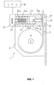
- Fig. 1 shows an embodiment of a seat belt retractor according to the present invention with the configuration partially omitted;
- Fig. 2 explains the setting of the load mode of a PFL shown in Fig. 1. (a) through (d) describe the setting of the light load mode, and (a), (b), (d), and (e) describe the setting of the heavy load mode;
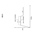
- Fig. 3 shows the properties of the FL load shown in Fig. 1;
- Fig. 4 is a block diagram for setting a
seat belt retractor 1 shown in Fig. 1 with the heavy/light load modes; - Fig. 5 is a longitudinal sectional view illustrating an embodiment of conventional seat belt retractors including a torsion bar;
- Fig. 6 shows an embodiment of conventional seat belt retractors including a torsion bar schematically; and
- Fig. 7 shows the properties of the FL load of a conventional embodiment shown in Fig. 6. Note that the same components as those of the conventional
-
- As shown in Fig. 1, the
seat belt retractor 1 of this embodiment, as with theseat belt retractor 1 of the conventional embodiment shown in Fig. 5, includes aframe 2 in the shape of a square with one end open, aseat belt 3, aspool 4 for retracting theseat belt 3, and a torsion bar (equivalent to the first seat belt load limiting mechanism according to the present invention) 7. Also, though not shown in the drawing, theseat belt retractor 1 of this embodiment, as with theseat belt retractor 1 shown in Fig. 5, includes deceleration sensing means 5,locking mechanism 6, spring means 8, apretensioner 11, and abush 12 for transmitting the seat belt retracting torque of thepretensioner 11 to thespool 4. - Furthermore, the
seat belt retractor 1 of this embodiment includes a programmable force limiter (hereinafter, referred to as PFL as appropriate) 20, and thisPFL 20 is disposed above thespool 4 and fixed to theframe 2.
ThePFL 20 can set the limit load (FL load) of a seat belt more flexibly according to the situation in an emergency by changing the limit load (FL load) of a seat belt in a collision based on the situation at the time of a collision (in an emergency) such as information to be confirmed before a collision (for example, information of the weight of the occupant, information of the slide position of the seat, and the like), severity of a collision (for example, collision speed, manner of collision, and the like).
Note that in Fig. 5 thepretensioner 11 is disposed above thespool 4, whereas in the case of theseat belt retractor 1 of this embodiment, since thePFL 20 is disposed above thespool 4, thepretensioner 11 is disposed below thespool 4, though not shown in the drawing. - This
PFL 20 comprises a main body 21, apressure piston 22 slidably provided within the main body 21 and including afemale screw 22a, apressure rod 23 fixed to thispressure piston 22 and provided within the main body 21 integrally and slidably with thepressure piston 22, anelectric motor 24 attached to the main body 21, a drivingshaft 25 connected to the rotational shaft of thismotor 24 so as to rotate integrally with the rotational shaft and including amale screw 25a which is screwed with thefemale screw 22a of thepressure piston 22, a T-shapedopening 26 provided in the main body 21 so that theseat belt 3 can movably pass therethrough and thepressure rod 23 can enter thereinto, andbelt receiving portions 27 for receiving theseat belt 3. Furthermore, a central processing unit (hereinafter, referred to as CPU as appropriate; equivalent to the limit load control means according to the present invention) 28, which is connected to themotor 24, for controlling the driving of thismotor 24 to control thePFL 20. - Subsequently, upon the
motor 24 driving and the drivingshaft 25 rotating, thepressure piston 22 moves in the direction of the shaft thereof (left and right directions in Fig. 1). In this case, in order to prevent thepressure piston 22 from rotating in accordance with rotation of the drivingshaft 25, for example, an arrangement may be made wherein a guide slot 22b is formed on thepressure piston 22 in the shaft direction, and also aguide rail 21a is provided in the main body 21, in which the guide slot 22b is fitted, and thispressure piston 22 moves in the shaft direction along theguide rail 21a while preventing rotation of thepressure piston 22. It is needless to mention that means are not restricted to this, other means for preventing rotation of thepressure piston 22 may be employed. - Upon the
pressure piston 22 moving rightward in Fig. 1, thepressure rod 23 also moves rightward, and atip 23a of thepressure rod 23 comes into contact with theseat belt 3, and pressed thisseat belt 3. Thus, theseat belt 3 is nipped between thetip 23a of thepressure rod 23 and the belt receiving portions 27 (described in detail later). At this time, thetip 23a of thepressure rod 23 is formed as a hemispheric curved surface, and also the edge portion of thebelt receiving portions 27 is formed roundly (R portion), and accordingly, theseat belt 3 is prevented from damage at the time of being nipped.
A limit load (PFL load) byPFL 20 is exerted on theseat belt 3 due to this nipping of theseat belt 3. Accordingly, thisPFL 20 makes up the limit load setting means according to the present invention. - Also note that the load mode in three stages of the FL load, i.e., (1) a load mode due to
inoperative PFL 20, (2) a light load mode, and (3) heavy load mode are set to theseat belt retractor 1 of this embodiment. - (1) The load mode due to
inoperative PFL 20 is a load mode due to torsion of the torsion bar, in which thePFL 20 does not activate (inoperative status shown in Fig. 1). In other words, an EA operation is performed only due to torsion of thetorsion bar 7, and the FL load F2 at this time is small as shown in Fig. 3. - (2) The light load mode is a load mode in which the driving force of the
motor 24 is set so as to be relatively small. More specifically, with the inoperative status of thePFL 20 shown in Fig. 2 (a), thepretensioner 11 is activated due to collision, thespool 4 rotates in the direction of retracting the seat belt so as to retract theseat belt 3 as indicated in Fig. 2(b), and the occupant is restrained by thepretensioner 11 in the same way as with the conventional embodiment. - Next, upon operation of the
pretensioner 11 being completed as shown in Fig. 2 (c), theseat belt 3 is withdrawn due to inertia of the occupant as with the conventional embodiment, thetorsion bar 7 is subjected to torsion, and themotor 24 is driven. Thus, bothpressure piston 22 andpressure rod 23 move rightward by driving of themotor 24. Theseat belt 3 is nipped between thetip 23a of thepressure rod 23 andbelt receiving portions 27 by thepressure rod 23 moving rightward. At this time, the driving force of themotor 24 is set small, and accordingly, the nipping force for theseat belt 3 is comparatively small. Accordingly, friction between thepressure rod 23 andbelt receiving portions 27 becomes comparatively small, and the light load mode, of which load for theseat belt 3 is small, is set. With this light load mode, PFL load is comparatively small. Accordingly, in this case, the FL load F3 of theseat belt 3, which is made up of this small PFL load and load due to the torsion of thetorsion bar 7, is comparatively small as shown by the solid line in Fig. 3. - Next, upon the
motor 24 being rotated in reverse, both thepressure piston 22 and thepressure rod 23 move leftward, and reach the inoperative position shown in Fig. 2 (d).
Thus, the operation of thePFL 20 is completed, thetip 23a of thepressure piston 23 is separated from theseat belt 3, and the nipping force for theseat belt 3 is released. Hereinafter, as with the conventional embodiment, an EA operation is performed by only thetorsion bar 7 being subjected to torsion, and the load mode due toinoperative PFL 20 mentioned above is set. Accordingly, the FL load F3 at this time is small as shown in Fig. 3. - (3) The heavy load mode is a load mode in which the driving force of the
motor 24 is set so as to be comparatively large. More specifically, as with the case of the aforementioned light load mode, bothpressure piston 22 andpressure rod 23 move rightward, and theseat belt 3 is nipped between thetip 23a of thepressure rod 23 and thebelt receiving portions 27. At this time, since the driving force of themotor 24 is set large, as shown in Fig. 2 (e), the amount of rightward movement of thepressure piston 22 andpressure rod 23 is greater than that in the case of the aforementioned light load mode, and consequently, the nipping force for theseat belt 3 becomes large. Thus, friction between thepressure rod 23 andbelt receiving portions 27 becomes large, and the heavy load mode, of which load for theseat belt 3 is large, is set. With this heavy load mode, PFL load is comparatively large. Accordingly, in this case, the FL load F4 of theseat belt 3, which is made up of this large PFL load and load due to the torsion of thetorsion bar 7, is comparatively large as shown in the dashed line in Fig. 3. - Next, as with the light load mode, upon the
motor 24 being rotated in reverse, both thepressure piston 22 and thepressure rod 23 reach the inoperative position shown in Fig. 2 (a), the operation of thePFL 20 is completed, and the nipping force for theseat belt 3 is released. Hereinafter, as with the conventional embodiment, an EA operation is performed by only thetorsion bar 7 being subjected to torsion, and the load mode due toinoperative PFL 20 mentioned above is set. Accordingly, the FL load F2 at this time is small as shown in Fig. 3.
Thus, thePFL 20 of the seat belt retractor of this embodiment is a friction-load-type PFL which can be activated repeatedly by controlling the rotational direction of themotor 24. - Fig. 4 is a block diagram for setting the
seat belt retractor 1 of this embodiment to the aforementioned three load modes.
In order to perform setting of the three load modes, theCPU 28 stores the predetermined conditions for activating thePFL 20. Subsequently, theCPU 28 changes the FL load at the time of a collision based on information to be confirmed before a collision (for example, information of the weight of the occupant, information of the slide position of the seat, and the like). - Accordingly, as shown in Fig. 4, the
CPU 28 is connected to themotor 24 as described above, and also aseat weight sensor 29 for detecting the seat load of a vehicle seat, i.e., the weight of the occupant, a seatslide position sensor 30 for detecting the slide position of the vehicle seat, anacceleration sensor 31 for detecting the acceleration of the vehicle, afront satellite sensor 32 for detecting the horizontal manner of collision at the front portion of the vehicle, and abuckle switch 33 which is turned on when the tongue is engaged with the buckle, are connected to theCPU 28. - Subsequently, the
CPU 28 sets theseat belt retractor 1 with any one of the aforementioned load modes in three stages by controlling themotor 24 to turn on (driving) or off (non-driving) following the conditions for activating thePFL 20 based on the information to be confirmed before a collision due to detection signals from theseat weight sensor 29, seatslide position sensor 30,acceleration sensor 31, andfront satellite sensor 32. Description will be made more specifically regarding the conditions for activating thePFL 20. - (a) Conditions for activating the
PFL 20 based on the weight of the occupant who sits on the vehicle seat.
These conditions are conditions for determining which of the aforementioned three stage load modes is set based on the weight of the occupant who sits on a vehicle seat. That is to say, - (i) In the case of a light and small occupant
→set the load mode due toinoperative PFL 20. - (ii) In the case of a middle-weight average occupant
→ set the light load mode. - (iii) In the case of a heavy and large occupant
→ set the heavy load mode.
The -
- (b) Conditions for activating the
PFL 20 based on the forward or backward slide position of the vehicle seat.
These conditions are conditions for determining which of the aforementioned three stage load modes is set based on the slide position of a vehicle seat. That is to say, - (i) In the case of a small occupant whose seat position
is forward
→ set the load mode due toinoperative PFL 20. - (ii) In the case of a medium occupant whose seat
position is around the middle
→ set the light load mode. - (iii) In the case of a large occupant whose seat
position is at the back
→ set the heavy load mode.
The -
- Furthermore, in the case of the
seat belt retractor 1 of this embodiment, whether or not thePFL 20 is allowed to act is determined based on the on or off state of thebuckle switch 33. More specifically, theCPU 28 sets thePFL 20 operative when a tongue is engaged with a buckle based on the on/off signal from thebuckle switch 33, on the other hand, sets thePFL 20 to inoperative when the tongue is not engaged with the buckle. - Furthermore, in the case of the
seat belt retractor 1 of this embodiment, the operation of thePFL 20 is changed based on the severity of a collision. More specifically, theCPU 28 determines whether the occupant is small or large (including medium) based on the detection signal from theseat weight sensor 29 or seatslide position sensor 30, and also determines whether the collision is a low-speed collision (20 to 30 km/h, for example, but not restricted to this) or middle-high-speed collision (30 km/h or higher, for example, but not restricted to this) based on the detection signal from theacceleration sensor 31. Subsequently, theCPU 28, in case that the occupant is small, sets the load mode due toinoperative PFL 20 in the event of a low-speed collision, and also sets the light load mode in the event of a middle-high-speed collision, further, in case that the occupant is large, sets the light load mode in the event of a low-speed collision, and also sets the heavy load mode in the event of a middle-high-speed collision. - Furthermore, in the case of the
seat belt retractor 1 of this embodiment, the operation timing of thePFL 20 is changed based on the severity of a collision. More specifically, theCPU 28 determines whether the collision is a low-speed collision (20 to 30 km/h, for example, but not restricted to this), middle-speed collision (30 to 40 km/h, for example, but not restricted to this), or high-speed collision (40 km/h or higher, for example, but not restricted to this) based on the detection signal from theacceleration sensor 31. Subsequently, in the event of a low-speed collision theCPU 28 sets the operation start timing of thePFL 20 slow (35 msec after collision, for example, but not restricted to this), and also in the event of a middle-speed collision sets the operation start timing of thePFL 20 comparatively slow (faster than that in the low-speed collision, 25 msec after collision, for example, but not restricted to this), further, in the event of a high-speed collision sets the operation start timing of thePFL 20 comparatively fast (15 msec after collision, for example, but not restricted to this). - Note that following a collision, the operation start timing of the
PFL 20 may be changed according to the crash severity of the vehicle. Also, the operation start timing of thePFL 20 may be changed with the fixed delay timing following the ignition of thepretensioner 11 along with the operation timing of thepretensioner 11. - Furthermore, in the case of the
seat belt retractor 1 of this embodiment, the operation of thePFL 20 is changed based on the severity and manner of collision. More specifically, theCPU 28 determines whether the collision is a collision offset to the right side or collision offset to the left side based on the detection signal from theacceleration sensor 31 and the detection signal from thefront satellite sensor 32. Subsequently, theCPU 28, in the event of a collision offset to the right side (collision inclined to the right side of the vehicle), sets the operation start timing of thePFL 20 fast at the retractor of the right-side seat belt equipment provided on the right-side seats, and also sets the operation start timing of thePFL 20 slow at the retractor of the left-side seat belt equipment provided on the left-side seats, and inversely, in the event of a collision offset to the left side (collision inclined to the left side of the vehicle), sets the operation start timing of thePFL 20 fast at the retractor of the left-side seat belt equipment provided on the left-side seats, and also sets the operation start timing of thePFL 20 slow at the retractor of the right-side seat belt equipment provided on the right-side seats. - Also, the
CPU 28 determines whether the collision is a right-side oblique collision or left-side oblique collision based on the detection signal from theacceleration sensor 31 and the detection signal from thefront satellite sensor 32. Subsequently, theCPU 28, in the event of the right-side oblique collision, sets the operation start timing of the right side of thePFL 20 fast, and also sets the operation start timing of the left side of thePFL 20 slow. Inversely, in the event of the left-side oblique collision, theCPU 28 sets the operation start timing of the left side of thePFL 20 fast, and also sets the operation start timing of the right side of thePFL 20 slow.
Thus, the second seat belt load limiting mechanism according to the present invention is configured of thePFL 20 andCPU 28.
The other configurations and other operations of theseat belt retractor 1 of this embodiment are the same as with the conventional embodiment shown in Fig. 5. - The
seat belt retractor 1 of this embodiment comprises thePFL 20 for changing the limit load (FL load) of the seat belt at the time of a collision based on information to be confirmed before a collision (for example, information of the weight of the occupant, information of the slide position of the seat, and the like), severity of a collision (for example, collision speed, manner of collision, and the like), and accordingly, the FL load of theseat belt 3 at the time of a collision can be set more flexibly and diversely depending on the situation at the time of a collision. Thus, the occupant can be restrained and protected more effectively and appropriately at the time of a collision. - Also, since the
PFL 20 can be activated again due to themotor 24, thePFL 20 can be activated repeatedly. Accordingly, even if thePFL 20 is activated once, there is no need to replace it with a new PFL, and it can be used again, thereby enabling reductions in costs. In this case, the pretensioner should be replaced when the pretensioner cannot be activated repeatedly, and on the other hand, the pretensioner should be used again when the pretensioner can be activated repeatedly.
In particular, since the known and existingtorsion bar 7 serving as the first seat belt load limiting mechanism is employed, the load limiting mechanism can be formed with a simple configuration at low cost. - Furthermore, since the load mode of the
seat belt retractor 1 is set with the three load modes of the load mode due toinoperative PFL 20, light load mode, and heavy mode, and the load for theseat belt 3 is controlled in three stages, the occupant can be restrained and protected more efficiently at the time of a collision. - Note that with the aforementioned embodiment, while the load mode is set in three stages, and the load for the
seat belt 3 is controlled in three stages, the number of stages is not restricted to this, more stages than two stages may be set, and the load for theseat belt 3 may be controlled consecutively.
Also, with the aforementioned embodiment, while thepretensioner 11 is provided, thepretensioner 11 is not always needed, and may be omitted. However, in order to restrain and protect the occupant more effectively at the time of a collision, thepretensioner 11 is preferably provided. - Furthermore, with the aforementioned embodiment, while description has been made regarding the case of a vehicle collision, when rotation of the locking
base 14 is locked, and a collision predicting sensor (a relative distance sensor for detecting the relative distance between the vehicle itself and an obstacle such as a forward obstacle or the like, a relative speed sensor for detecting a relative speed between the vehicle itself and the vehicle in front of the vehicle itself, as well as the aforementionedvarious sensors motor 24 is driven, the load is exerted on theseat belt 3 by thePFL 20 as described above, following which thePFL 20 may be set in a non-activated status by rotating themotor 24 inversely when the collision is prevented. In this case, thePFL 20 can be activated again. - Furthermore, with the aforementioned embodiment, while the
torsion bar 7 is employed as the first seat belt load limiting mechanism, an EA mechanism disclosed in theaforementioned Patent Documents 2 through 6 may be employed instead of thistorsion bar 7. Also, an EA mechanism for severing a plate-shaped energy absorption member provided on the locking base side with a severing protrusion provided on the spool side, which has been subjected to application for patent by the Present Inventor (Japanese Unexamined Patent Application No. 2003-206807), may be employed as the first seat belt load limiting mechanism. - The seat belt retractor according to the present invention can be advantageously employed for a seat belt retractor for a seat belt deice equipped in a vehicle such as an automobile, wherein the load exerted on the seat belt in an emergency such as a collision and so forth is limited so that the impact energy exerted on the occupant is absorbed and alleviated, while the seat belt is prevented from being withdrawn.
Claims (3)
- A seat belt retractor comprising at least:wherein said second seat belt load limiting mechanism comprises limit load setting means for setting the limit load for said seat belt, and limit load control means for controlling said limit load setting means to change the limit load of said seat belt in an emergency based on the situation in the emergency;a spool for retracting a seat belt;a locking mechanism including a locking member of which rotation in the direction of withdrawing said seat belt is prevented in an emergency; andfirst and second seat belt load limiting mechanisms for limiting load to be exerted on said seat belt when rotation of said locking member in the direction of withdrawing said seat belt is prevented with said spool rotating relative to said locking member in the direction of withdrawing said seat belt,
and wherein said limit load setting means are means capable of working repeatedly. - A seat belt retractor according to Claim 1, wherein said first seat belt load limiting mechanism comprises any one of:a load limiting mechanism for subjecting a torsion bar provided between said spool and said locking member to torsion deformation;a load limiting mechanism for drawing a wire rod provided on any one side of said spool side and said locking base side through among engagement pins provided on the other side;a load limiting mechanism for forcing a band plate provided on either one of said spool side and said locking base side to be forcibly deformed by a guide slot provided on the other side;a load limiting mechanism for subjecting a tubular member provided on either one of said spool side and said locking base side to plastic deformation with a latching portion provided on the other side;a load limiting mechanism for subjecting a U-shaped flat plate material of which one end is provided on either one of said spool side and said locking base side, and the other end is engaged with the other side to deformation;a load limiting mechanism for subjecting a shear pin provided between said spool and said locking base to shear fracturing;an EA mechanism for cutting a section to be cut provided on either one of said spool side and said locking base side with a cutting blade provided on the other side; anda load limiting mechanism for severing a plate-shaped energy absorption member provided on either one of said spool side and said locking base side with a severing protrusion provided on the other side.
- A seat belt retractor according to Claim 1 or 2, wherein load modes in the three stages of a load mode due to the limit load setting means being inoperative, a light load mode, and a heavy load mode, are set to said limit load beforehand.
Applications Claiming Priority (2)
| Application Number | Priority Date | Filing Date | Title |
|---|---|---|---|
| JP2003421073 | 2003-12-18 | ||
| JP2003421073A JP2005178514A (en) | 2003-12-18 | 2003-12-18 | Seat belt retractor |
Publications (2)
| Publication Number | Publication Date |
|---|---|
| EP1544062A1 true EP1544062A1 (en) | 2005-06-22 |
| EP1544062B1 EP1544062B1 (en) | 2008-06-04 |
Family
ID=34510665
Family Applications (1)
| Application Number | Title | Priority Date | Filing Date |
|---|---|---|---|
| EP04028723A Expired - Lifetime EP1544062B1 (en) | 2003-12-18 | 2004-12-03 | Seat belt retractor |
Country Status (5)
| Country | Link |
|---|---|
| US (1) | US7350735B2 (en) |
| EP (1) | EP1544062B1 (en) |
| JP (1) | JP2005178514A (en) |
| CN (1) | CN1629016A (en) |
| DE (1) | DE602004014236D1 (en) |
Cited By (8)
| Publication number | Priority date | Publication date | Assignee | Title |
|---|---|---|---|---|
| EP1717113A3 (en) * | 2005-04-26 | 2008-03-19 | Takata Corporation | Seatbelt retractor and seatbelt device equipped with the seatbelt retractor |
| DE102006048350A1 (en) * | 2006-10-12 | 2008-04-17 | Trw Automotive Gmbh | Support force limiting method for passenger support system for belt, involves adjusting level of force limitation depending on position of vehicle seat, which is representative for body size and/or weight of passenger |
| DE102008000981A1 (en) | 2008-04-03 | 2009-10-08 | Robert Bosch Gmbh | Belt rolling unit for belt strap of belt system for passenger protection system in vehicle, has effective outer diameter of spindle which is reduced in belt strap for limiting current effective force determined in belt strap |
| DE102008000966A1 (en) | 2008-04-03 | 2009-10-08 | Robert Bosch Gmbh | Belt rolling unit for belt strap of belt system for passenger protection system in vehicle, has rolling module with spindle, on which belt strap is rolled |
| DE102008000972A1 (en) | 2008-04-03 | 2009-10-08 | Robert Bosch Gmbh | Belt retractor unit for passenger protection system in motor vehicle, has impairment tool i.e. clamp, degrading overall structure of belt strap for limiting force acting on strap in case of accident to produce movement of strap |
| DE102008041508A1 (en) | 2008-08-25 | 2010-03-04 | Robert Bosch Gmbh | Belt rolling unit for use in belt system for occupant protection system in vehicle, has belt band and corresponded rolling module which is supported in fastening unit |
| DE102008042020A1 (en) | 2008-09-12 | 2010-03-18 | Robert Bosch Gmbh | Belt retractor unit for use in e.g. belt system, for passenger protection system in motor vehicle, has brake arrangement implemented as eddy current brake, which is coupled with spindle using adjustable magnetic field |
| DE102008043019A1 (en) | 2008-10-21 | 2010-04-22 | Robert Bosch Gmbh | Belt retractor unit for e.g. belt system utilized for occupant protection system in commercial aircraft, has torsional bar limiting force acting on belt strap during accident, where torsion characteristics of bar are changeable |
Families Citing this family (8)
| Publication number | Priority date | Publication date | Assignee | Title |
|---|---|---|---|---|
| US20070007066A1 (en) * | 2005-07-08 | 2007-01-11 | Siemens Vdo Automotive Corporation | Peak load detection determination for deploying load limiting restraint devices |
| US8478488B2 (en) * | 2006-03-28 | 2013-07-02 | Ford Global Technologies | Impact event countermeasure control method and system for automotive vehicle |
| JP2007284014A (en) * | 2006-04-20 | 2007-11-01 | Takata Corp | Seat belt retractor and seat belt device |
| JP4907249B2 (en) * | 2006-07-19 | 2012-03-28 | タカタ株式会社 | Seat belt retractor and seat belt device |
| JP4811942B2 (en) * | 2006-11-01 | 2011-11-09 | タカタ株式会社 | Seat belt retractor and seat belt device provided with the same |
| JP5730677B2 (en) * | 2011-06-13 | 2015-06-10 | 芦森工業株式会社 | Seat belt retractor |
| US10525923B2 (en) * | 2017-09-08 | 2020-01-07 | Ford Global Technologies, Llc | Belt load modulation for vehicle front oblique impacts |
| US11554749B2 (en) | 2020-01-23 | 2023-01-17 | Ford Global Technologies, Llc | Load-limiting seatbelt retractor |
Citations (3)
| Publication number | Priority date | Publication date | Assignee | Title |
|---|---|---|---|---|
| DE19604483C1 (en) * | 1996-02-08 | 1997-03-20 | Autoliv Dev | Car safety-belt with controlled retaining force |
| EP1022201A1 (en) * | 1999-01-22 | 2000-07-26 | Breed Automotive Technology, Inc. | Seat belt retractor |
| DE20015402U1 (en) * | 2000-09-06 | 2001-01-18 | TRW Occupant Restraint Systems GmbH & Co. KG, 73553 Alfdorf | Belt retractor for a vehicle seat belt |
Family Cites Families (13)
| Publication number | Priority date | Publication date | Assignee | Title |
|---|---|---|---|---|
| BR9709962A (en) * | 1996-06-26 | 1999-08-10 | Autoliv Dev | Strap reel device with adjustable force limiting device |
| JPH10258702A (en) | 1997-01-17 | 1998-09-29 | Tokai Rika Co Ltd | Webbing take-up device |
| US5788177A (en) * | 1997-02-21 | 1998-08-04 | Alliedsignal Inc. | Multi-level load limiting retractor |
| US6012667A (en) * | 1998-02-19 | 2000-01-11 | Breed Automotive Technology Inc. | Multi-level load limiting torsion bar retractor |
| JP3655745B2 (en) * | 1998-04-16 | 2005-06-02 | タカタ株式会社 | Seat weight measuring device |
| DE29816280U1 (en) * | 1998-09-10 | 1999-01-21 | TRW Occupant Restraint Systems GmbH & Co. KG, 73553 Alfdorf | Force limiting device |
| DE19927427C2 (en) * | 1999-06-16 | 2002-11-14 | Autoliv Dev | Belt retractor with switchable force limiter |
| JP4662214B2 (en) * | 1999-08-18 | 2011-03-30 | タカタ株式会社 | Seat belt retractor |
| JP2001106025A (en) * | 1999-09-30 | 2001-04-17 | Takata Corp | Seat belt retractor |
| JP2002053008A (en) | 1999-12-27 | 2002-02-19 | Nsk Ltd | Seat belt device with seat belt retractor with energy absorption mechanism |
| JP3723423B2 (en) | 2000-05-31 | 2005-12-07 | エヌエスケー・オートリブ株式会社 | Seat belt device |
| JP2003019945A (en) | 2001-07-09 | 2003-01-21 | Nsk Autoliv Co Ltd | Seat belt device |
| JP4559666B2 (en) * | 2001-07-11 | 2010-10-13 | 株式会社東海理化電機製作所 | Webbing take-up device |
-
2003
- 2003-12-18 JP JP2003421073A patent/JP2005178514A/en not_active Withdrawn
-
2004
- 2004-12-03 DE DE602004014236T patent/DE602004014236D1/en not_active Expired - Fee Related
- 2004-12-03 EP EP04028723A patent/EP1544062B1/en not_active Expired - Lifetime
- 2004-12-10 US US11/008,599 patent/US7350735B2/en not_active Expired - Fee Related
- 2004-12-17 CN CNA2004100821601A patent/CN1629016A/en active Pending
Patent Citations (3)
| Publication number | Priority date | Publication date | Assignee | Title |
|---|---|---|---|---|
| DE19604483C1 (en) * | 1996-02-08 | 1997-03-20 | Autoliv Dev | Car safety-belt with controlled retaining force |
| EP1022201A1 (en) * | 1999-01-22 | 2000-07-26 | Breed Automotive Technology, Inc. | Seat belt retractor |
| DE20015402U1 (en) * | 2000-09-06 | 2001-01-18 | TRW Occupant Restraint Systems GmbH & Co. KG, 73553 Alfdorf | Belt retractor for a vehicle seat belt |
Cited By (10)
| Publication number | Priority date | Publication date | Assignee | Title |
|---|---|---|---|---|
| EP1717113A3 (en) * | 2005-04-26 | 2008-03-19 | Takata Corporation | Seatbelt retractor and seatbelt device equipped with the seatbelt retractor |
| DE102006048350A1 (en) * | 2006-10-12 | 2008-04-17 | Trw Automotive Gmbh | Support force limiting method for passenger support system for belt, involves adjusting level of force limitation depending on position of vehicle seat, which is representative for body size and/or weight of passenger |
| DE102008000981A1 (en) | 2008-04-03 | 2009-10-08 | Robert Bosch Gmbh | Belt rolling unit for belt strap of belt system for passenger protection system in vehicle, has effective outer diameter of spindle which is reduced in belt strap for limiting current effective force determined in belt strap |
| DE102008000966A1 (en) | 2008-04-03 | 2009-10-08 | Robert Bosch Gmbh | Belt rolling unit for belt strap of belt system for passenger protection system in vehicle, has rolling module with spindle, on which belt strap is rolled |
| DE102008000972A1 (en) | 2008-04-03 | 2009-10-08 | Robert Bosch Gmbh | Belt retractor unit for passenger protection system in motor vehicle, has impairment tool i.e. clamp, degrading overall structure of belt strap for limiting force acting on strap in case of accident to produce movement of strap |
| DE102008000972B4 (en) * | 2008-04-03 | 2017-06-22 | Robert Bosch Gmbh | Belt reel unit and method for rolling up at least one webbing and belt system for an occupant protection system in a vehicle with at least one such belt reel unit |
| DE102008000981B4 (en) | 2008-04-03 | 2018-09-20 | Robert Bosch Gmbh | Belt reel unit and method for rolling up at least one webbing and belt system for an occupant protection system in a vehicle with at least one such belt reel unit |
| DE102008041508A1 (en) | 2008-08-25 | 2010-03-04 | Robert Bosch Gmbh | Belt rolling unit for use in belt system for occupant protection system in vehicle, has belt band and corresponded rolling module which is supported in fastening unit |
| DE102008042020A1 (en) | 2008-09-12 | 2010-03-18 | Robert Bosch Gmbh | Belt retractor unit for use in e.g. belt system, for passenger protection system in motor vehicle, has brake arrangement implemented as eddy current brake, which is coupled with spindle using adjustable magnetic field |
| DE102008043019A1 (en) | 2008-10-21 | 2010-04-22 | Robert Bosch Gmbh | Belt retractor unit for e.g. belt system utilized for occupant protection system in commercial aircraft, has torsional bar limiting force acting on belt strap during accident, where torsion characteristics of bar are changeable |
Also Published As
| Publication number | Publication date |
|---|---|
| DE602004014236D1 (en) | 2008-07-17 |
| US7350735B2 (en) | 2008-04-01 |
| US20050134101A1 (en) | 2005-06-23 |
| JP2005178514A (en) | 2005-07-07 |
| CN1629016A (en) | 2005-06-22 |
| EP1544062B1 (en) | 2008-06-04 |
Similar Documents
| Publication | Publication Date | Title |
|---|---|---|
| EP1544062B1 (en) | Seat belt retractor | |
| EP1867533B1 (en) | Seatbelt retractor and seatbelt apparatus using the same | |
| EP1211147B1 (en) | Seatbelt retractor | |
| EP1918165B1 (en) | Seat belt retractor and seat belt apparatus comprising the same | |
| US20080290644A1 (en) | Re-settable vehicle seat belt buckle pre-tensioner presenter system and method of operation | |
| US20030094326A1 (en) | Device for determining the load on a vehicle occupant | |
| US10668895B2 (en) | Variable force limiter control system for vehicle | |
| US8403423B2 (en) | Method of limiting a load applied on a seat belt in an emergency | |
| US6435441B1 (en) | Seat belt retractor | |
| JP2011230691A (en) | Control device of seat belt retractor, and seat belt device including the same | |
| EP1717113A2 (en) | Seatbelt retractor and seatbelt device equipped with the seatbelt retractor | |
| US9592791B2 (en) | Advanced seatbelt apparatus | |
| US20060022077A1 (en) | Brake system, seatbelt system and seatbelt retractor | |
| JP2006062632A (en) | Seatbelt retractor and seatbelt system having the same | |
| US7360795B2 (en) | Torsion bar load limiter and pretensioner for seat belt system | |
| US20060022078A1 (en) | Seatbelt retractor and seatbelt system | |
| US8165760B2 (en) | Method and system for electronically operating a vehicle occupant seat safety restraint system | |
| JP2007083883A (en) | Vehicle seat belt control device | |
| JP4722619B2 (en) | Vehicle seat belt device | |
| JP2011230690A (en) | Control device of seat belt retractor, and seat belt device including the same | |
| EP1621418A1 (en) | Locking system, seatbelt retractor and seatbelt system incorporating the locking system | |
| JP2008105552A (en) | Vehicle seat belt control device | |
| JP4222222B2 (en) | Seat belt pretensioner | |
| KR101200777B1 (en) | Retractor and seat belt therewith | |
| JP2001114070A (en) | Seat belt device for vehicle, and occupant crash protection method when vehicle collides |
Legal Events
| Date | Code | Title | Description |
|---|---|---|---|
| PUAI | Public reference made under article 153(3) epc to a published international application that has entered the european phase |
Free format text: ORIGINAL CODE: 0009012 |
|
| AK | Designated contracting states |
Kind code of ref document: A1 Designated state(s): AT BE BG CH CY CZ DE DK EE ES FI FR GB GR HU IE IS IT LI LT LU MC NL PL PT RO SE SI SK TR |
|
| AX | Request for extension of the european patent |
Extension state: AL BA HR LV MK YU |
|
| 17P | Request for examination filed |
Effective date: 20051110 |
|
| AKX | Designation fees paid |
Designated state(s): DE FR GB SE |
|
| 17Q | First examination report despatched |
Effective date: 20060222 |
|
| GRAP | Despatch of communication of intention to grant a patent |
Free format text: ORIGINAL CODE: EPIDOSNIGR1 |
|
| GRAS | Grant fee paid |
Free format text: ORIGINAL CODE: EPIDOSNIGR3 |
|
| GRAA | (expected) grant |
Free format text: ORIGINAL CODE: 0009210 |
|
| AK | Designated contracting states |
Kind code of ref document: B1 Designated state(s): DE FR GB SE |
|
| REG | Reference to a national code |
Ref country code: GB Ref legal event code: FG4D |
|
| REF | Corresponds to: |
Ref document number: 602004014236 Country of ref document: DE Date of ref document: 20080717 Kind code of ref document: P |
|
| PG25 | Lapsed in a contracting state [announced via postgrant information from national office to epo] |
Ref country code: SE Free format text: LAPSE BECAUSE OF FAILURE TO SUBMIT A TRANSLATION OF THE DESCRIPTION OR TO PAY THE FEE WITHIN THE PRESCRIBED TIME-LIMIT Effective date: 20080904 |
|
| PLBE | No opposition filed within time limit |
Free format text: ORIGINAL CODE: 0009261 |
|
| STAA | Information on the status of an ep patent application or granted ep patent |
Free format text: STATUS: NO OPPOSITION FILED WITHIN TIME LIMIT |
|
| 26N | No opposition filed |
Effective date: 20090305 |
|
| GBPC | Gb: european patent ceased through non-payment of renewal fee |
Effective date: 20081203 |
|
| REG | Reference to a national code |
Ref country code: FR Ref legal event code: ST Effective date: 20090831 |
|
| PG25 | Lapsed in a contracting state [announced via postgrant information from national office to epo] |
Ref country code: DE Free format text: LAPSE BECAUSE OF NON-PAYMENT OF DUE FEES Effective date: 20090701 |
|
| PG25 | Lapsed in a contracting state [announced via postgrant information from national office to epo] |
Ref country code: GB Free format text: LAPSE BECAUSE OF NON-PAYMENT OF DUE FEES Effective date: 20081203 |
|
| PG25 | Lapsed in a contracting state [announced via postgrant information from national office to epo] |
Ref country code: FR Free format text: LAPSE BECAUSE OF NON-PAYMENT OF DUE FEES Effective date: 20081231 |