EP1543739A2 - End stop for slide fastener - Google Patents
End stop for slide fastener Download PDFInfo
- Publication number
- EP1543739A2 EP1543739A2 EP04029812A EP04029812A EP1543739A2 EP 1543739 A2 EP1543739 A2 EP 1543739A2 EP 04029812 A EP04029812 A EP 04029812A EP 04029812 A EP04029812 A EP 04029812A EP 1543739 A2 EP1543739 A2 EP 1543739A2
- Authority
- EP
- European Patent Office
- Prior art keywords
- end stop
- rod
- fastener
- fused portion
- fused
- Prior art date
- Legal status (The legal status is an assumption and is not a legal conclusion. Google has not performed a legal analysis and makes no representation as to the accuracy of the status listed.)
- Granted
Links
Images





Classifications
-
- A—HUMAN NECESSITIES
- A44—HABERDASHERY; JEWELLERY
- A44B—BUTTONS, PINS, BUCKLES, SLIDE FASTENERS, OR THE LIKE
- A44B19/00—Slide fasteners
- A44B19/24—Details
- A44B19/38—Means at the end of stringer by which the slider can be freed from one stringer, e.g. stringers can be completely separated from each other
-
- A—HUMAN NECESSITIES
- A44—HABERDASHERY; JEWELLERY
- A44B—BUTTONS, PINS, BUCKLES, SLIDE FASTENERS, OR THE LIKE
- A44B19/00—Slide fasteners
- A44B19/24—Details
- A44B19/36—Means for permanently uniting the stringers at the end; Means for stopping movement of slider at the end
-
- Y—GENERAL TAGGING OF NEW TECHNOLOGICAL DEVELOPMENTS; GENERAL TAGGING OF CROSS-SECTIONAL TECHNOLOGIES SPANNING OVER SEVERAL SECTIONS OF THE IPC; TECHNICAL SUBJECTS COVERED BY FORMER USPC CROSS-REFERENCE ART COLLECTIONS [XRACs] AND DIGESTS
- Y10—TECHNICAL SUBJECTS COVERED BY FORMER USPC
- Y10T—TECHNICAL SUBJECTS COVERED BY FORMER US CLASSIFICATION
- Y10T24/00—Buckles, buttons, clasps, etc.
- Y10T24/25—Zipper or required component thereof
- Y10T24/2596—Zipper or required component thereof including means attaching interlocking surfaces together
-
- Y—GENERAL TAGGING OF NEW TECHNOLOGICAL DEVELOPMENTS; GENERAL TAGGING OF CROSS-SECTIONAL TECHNOLOGIES SPANNING OVER SEVERAL SECTIONS OF THE IPC; TECHNICAL SUBJECTS COVERED BY FORMER USPC CROSS-REFERENCE ART COLLECTIONS [XRACs] AND DIGESTS
- Y10—TECHNICAL SUBJECTS COVERED BY FORMER USPC
- Y10T—TECHNICAL SUBJECTS COVERED BY FORMER US CLASSIFICATION
- Y10T24/00—Buckles, buttons, clasps, etc.
- Y10T24/25—Zipper or required component thereof
- Y10T24/2598—Zipper or required component thereof including means for obstructing movement of slider
Definitions
- the present invention relates to a top end stop and bottom end stop for a slide fastener in which coil type, or zigzag type linear fastener elements made of synthetic resin are mounted on a side edge of a fastener tape and a hidden type slide fastener.
- top end stops and bottom end stops in the coil type or zigzag type linear slide fastener and hidden type slide fastener made of synthetic resin have been proposed.
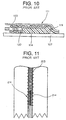
- a synthetic resin piece 114 having a circular section is formed in the back surface of the heads 120 of the tape 107 side of plural elements at a final end of the linear fastener element row 103, such that it can be fused as shown in FIG. 10 and an end portion of the synthetic resin piece 114 located at a final end of the element row 103 is bent to the surface so as to produce a bent portion 119.
- the end face of the bent portion 119 is formed lower than the surface of the elements and then, the bent portion 119 is fused with a coupling face formed in a curved state on a side face of the element head 120 at the final end of the element row 103.
- a synthetic resin piece 114 is fused to the bottom face of a head of the linear fastener element row 113 by ultrasonic processing with a pressure and the end portion thereof is bent to the surface side of the element and fused to the side face of the element head 120. Because the fusing process for the synthetic resin is very complicated, this cannot be produced at a cheap price. Further, because the synthetic resin piece 114 is fused with the surface of the elements, there is a fear that it may be separated during usage.
- a prominent object of the present invention is to provide an end stop for a slide fastener, which serves as a top end stop and bottom end stop for preventing a slider from slipping out of an ordinary type or hidden type slide fastener equipped with a linear fastener element row of synthetic resin, the top end stop and bottom end stop being produced by, after a rod-like body of synthetic resin is inserted into liner fastener elements, fusing only an end portion thereof, so that these end stops are never separated or affected by deterioration, thereby ensuring a rigid structure and a cheap price.
- Another object of the present invention is to provide an end stop for a slide fastener which can be completed as a rigid structure by specifying a range of a portion to be fused together in the rod-like body.
- Still another object of the present invention is to provide an end stop for a slide fastener which can be produced as a top end stop easily by disposing the rod-like body of synthetic resin in the linear fastener element row in an ideal form.
- a further object of the present invention is to provide an end stop for a slide fastener which can be produced as a bottom end stop easily by disposing the rod-like body of synthetic resin in the linear fastener element row in an ideal form.
- a still further object of the present invention is to provide an end stop for a slide fastener which is sewed on a side edge of the linear fastener element row so that it can be employed effectively as an ordinary type slide fastener or a hidden type slide fastener.
- a yet still further object of the present invention is to provide an end stop for a slide fastener which can be employed effectively as an end stop for a coil type slide fastener formed of coil type fastener elements.
- a further object of the present invention is to provide an end stop for a slide fastener which can be employed as an end stop for a zigzag type slide fastener formed of zigzag type fastener elements.
- an end stop for a slide fastener being characterized in that a linear fastener element row of synthetic resin is mounted on a side edge of a fastener tape; a rod-like body of synthetic resin is inserted into a coupling space portion located in an inside of coupling heads in plural fastener elements located at an end of the fastener element row; a fused portion is provided by fusing the several fastener elements of the plural fastener elements in which the rod-like body is inserted with the rod-like body; and a non-fused portion is formed without fusing the fastener elements of the plural fastener elements in which the rod-like body is inserted except the fastener elements fused with the rod-like body as the fused portion with the rod-like body so as to form the end stop.
- the end stop is fused integrally and hence a rigid end stop can be completed. Further, because the non-fused portion is formed in the end stop, the sewing yarn of the inner end portion of the end stop is not subjected to deterioration by heat generated upon ultrasonic wave welding, so that that sewing yarn is never cut out even due to concentration of stress generated when the slide fastener is opened or closed. Thus, this end stop can bear a long term use thereby ensuring a good quality and contributing to expansion of sales.
- the fused portion is provided on an outer end portion of the rod-like body.
- a length of the fused portion in a longitudinal direction of the rod-like body is in a range of half or less of the length of the rod-like body.
- a first fused portion is provided on the outer end portion of the rod-like body
- a second fused portion is provided on an inner end portion of the rod-like body
- the non-fused portion is provided between the first fused portion and the second fused portion.
- a length of the first fused portion in a longitudinal direction of the rod-like body is longer than the length of the second fused portion.
- a length of the non-fused portion in a longitudinal direction of the rod-like body is in a range of less than a sum of the length of the first fused portion and the length of the second fused portion.
- a length of the first fused portion in a longitudinal direction of the rod-like body is longer than the length of the second fused portion and the length of the non-fused portion.
- the second fused portion prevents the inner end portion of the rod-like body from escaping from the inside of the coil type fastener elements at the time when the slider moves to the location where the slider contacts with the bottom end stop, right and left coil type fastener elements are separated, and the coil type fastener elements in the inner end portion side of the bottom end stop are pushed and opened in the right and left directions.
- the rod-like body is not fused with the coil type fastener elements too tightly, and the fused rod-like body and the coil type fastener elements do not become fragile and are not damaged.
- the bottom end stop does not become rigid, even if the slider moves toward the bottom end stop and butts the bottom end stop, the non-fused portion bends slightly and changes its shape so that it alleviates the impact strength and prevents the damage of bottom end stop.
- the rod-like body is inserted into the linear fastener element row in a separated state so as to form a top end stop. Consequently, by inserting the rod-like body into the fastener stringer in which the linear fastener elements are in the separated state, the top end stop can be produced easily.
- the rod-like body is inserted into the linear fastener element row in a coupled state so as to form a bottom end stop. Consequently, by adopting the rod-like body to the fastener chain in which the linear fastener elements are in a coupled state, the bottom end stop can be produced easily.
- the linear fastener element row is disposed on the side edge of the fastener tape and sewed with a sewing yarn. Consequently, a good quality end stop can be applied to an ordinary type slide fastener and a hidden type slide fastener formed of the linear fastener element row easily.
- the linear fastener element row is formed of coil type fastener elements. Consequently, a good quality end stop can be applied to a slide fastener formed of the coil type fastener elements easily.
- the linear fastener element row is formed of zigzag type fastener elements. Consequently, a good quality end stop can be applied to a slide fastener formed of the zigzag type fastener elements easily. The effects which the present invention exerts are considerably great.
- An end stop for a slide fastener of the present invention is an end stop comprising a top end stop 12 and a bottom end stop 11, which are to be mounted on a top end and a bottom end respectively of a slide fastener as shown in FIG. 1.
- coil type fastener elements 5 are formed by winding a mono-filament made of polyamide or polyester in the form of a coil
- zigzag type fastener elements 6 are formed by bending a mono-filament in a zigzag shape so as to form a linear fastener element row 3 respectively.
- This linear fastener element row 3 is sewed to a side edge of a fastener tape 7 by sewing yarn 8 so as to finish an ordinary type coil slide fastener or zigzag slide fastener.
- the linear fastener element row 3 can be sewed on the surface of a folded back portion 25 formed on a side edge of the fastener tape 7 with the sewing yarn 8 so as to finish a hidden type slide fastener.
- the end stop 10 is formed by cutting out a rod-like body 14 formed of polyester mono-filament to an appropriate length depending on the size of the slide fastener and this rod-like body 14 is inserted into a coupling space portion 23 existing in the backside of coupling heads 20 of plural fastener elements 4 at an end portion of the linear fastener element row 3.
- the coupling space portion 23 is a space in which the expanded portion of the coupling head 20 of a mating fastener element 4 invades when the fastener elements 4 opposing of paired fastener stringers 2 engage each other. Because the coupling space portion 23 exists even if the fastener elements 4 are in a coupled state or in a non-coupled state, the rod-like body 14 is inserted using this coupling space portion 23.
- the rod-like body 14 inserted into the coupling space portion 23 is comprised of an outer end portion 17 located on the side of a distal end of the linear fastener element row 3 and an inner end portion 18 located on an inner side of the linear fastener element row 3 at the side opposite to the outer end portion 17.
- a fused portion 15 is formed by fusing together the fastener elements 4 of several pitches located on the side of the outer end portion 17 with the rod-like body 14 by ultrasonic welding with an ultrasonic wave processing machine.
- a non-fused portion 16 is formed without fusing together the fastener elements 4 of several pitches located on the side of the inner end portion 18 with the rod-like body 14 so as to form the end stop 10 for the slider of the top end stop 12 or bottom end stop 11.
- the top end side of the end stop 10 is a portion in which a load such as pulling force or twisting force is concentrated on the sewing yarn 8 when the linear fastener element rows 3 are engaged with each other or separated from each other by sliding the slider 27. Therefore, that the non-fused portion 16 of the rod-like body 14 is formed on the top end side of the end stop 10 while the fused portion 15 is formed on the bottom end side is feature of the present invention. Because the sewing yarn 8 near the non-fused portion 16 is never affected by heat upon ultrasonic welding, the sewing yarn 8 is not deteriorated at all and never cut out when the slide fastener is opened/closed.
- Coil-type fastener elements 5 are formed by winding a mono-filament of polyamide or polyester in the form of a coil and a core thread 9 is inserted into the inside of the coil type fastener elements 5 so as to form the linear fastener element row 3.
- This linear fastener element rows 3 are mounted on the top face on a side edge of the fastener tape 7 by sewing with the double-ring sewing type sewing yarn 8 with two needles and three threads so as to form a continuous fastener chain 1.
- the coil type fastener elements are cut out by a predetermined length so as to form a space in which no coil type fastener elements 5 exist on the top face on the side edge of the fastener tape 7.
- the fastener chain 1 of a unit length is completed.
- the rod-like body 14 formed of mono-filament of the same material as the coil-type fastener element 5 is cut to a predetermined length and inserted into the coupling space portion 23 existing in the backside of the coupling head 20 in a state in which the coil-type fastener elements 5 engage each other at an end of the fastener chain 1 and then, fused together by ultrasonic welding with an ultrasonic wave processing machine.
- ultrasonic welding only the outer end portion 17 of the inserted rod-like body 14, that is, the portion which serves as the lower end portion of the end stop 10 is fused together with the coil type fastener elements 5 and this ultrasonic welding is carried out from the front side of the coil type fastener element 5.
- the slightly dented fused portion 15 is formed in the surface of the element 5.
- the non-fused portion 16 without fusing the inner end portion 18 of the rod-like body 14, that is, the portion which serves as the upper end portion of the end stop 10 with the coil-type fastener element 5, the bottom end stop 11 is formed so as to complete the end stop 10 for the slider.
- the coupling space portion 23 is a space surrounded by the coupling head 20, upper/lower leg portions 21 connected to the top end and bottom end of the coupling head 20 and the core thread 9 inserted through the inside of the elements 5.
- the length of the rod-like body 14 of the mono-filament is about 7 mm and the length of the fused portion 15 is about 3 mm while the length of the non-fused portion 16 is about 4mm.
- the end stop having the same configuration can be formed in a woven slide fastener in which the coil-type fastener elements are woven into a side of the fastener tape at the same time when the fastener tape is woven. Further, the end stop having the same configuration can be formed in a knitted slide fastener in which the coil-type fastener elements are knitted into a side of the tape at the same time when the fastener tape is knitted.
- a slide fastener according to a second embodiment of the invention shown in FIG. 5 concerns a hidden type slide fastener in which the coil-type fastener elements 5 are not visible from the surface of the fastener tape 7.
- a folded back portion 25 is formed by inverting a side of the fastener tape 7 and the coil-type fastener elements 5 are sewed on the surface of this folded back portion 25 with the sewing yarn 8 through the core thread 9 so as to form a continuous hidden fastener chain 1.
- a space portion is provided and by cutting out the fastener tape 7 at this space portion, the fastener chain 1 of a predetermined length is produced.
- the rod-like body 14 of a predetermined length formed of mono-filament of the same material as the coil-type fastener element 5 is inserted into the coupling space portion 23 existing in the backside of the coupling head 20 in a state in which the coupling heads 20 engage at an end of the hidden type fastener chain 1, and by forming the fused portion 15 in which only the outer end portion 17 is fused by ultrasonic welding the rod-like body 14 and the non-fused portion 16 in which the inner end portion 18 is not fused, the bottom end stop 11 of the hidden type fastener chain 1 is formed so as to form the end stop 10 for the slider.
- the coupling space portion 23 is a space surrounded by the coupling head 20, upper/lower leg portions 21 connected to the top end and bottom end of the coupling head 20 and the core thread 9 inserted through the inside of the elements 5.
- a slide fastener for a third embodiment of the invention shown in FIG. 6 is a zigzag type slide fastener using zigzag type fastener elements 6.
- the zigzag type fastener elements 6 are formed by bending a mono-filament made of resin in a zigzag form, the front and rear sides of a side edge of the fastener tape 7 are sandwiched by the zigzag type fastener elements 6 and the portion between the leg portions 21 in a sandwiched state is mounted by sewing with the sewing yarn 8 so as to form the continuous fastener element 1.
- this continuous fastener chain 1 by cutting out the zigzag type fastener elements 6 by a predetermined length, the space portion is provided and then, by cutting out the fastener tape 7 at this space portion, the fastener chain 1 is produced.
- the rod-like body 14 of a predetermined length formed of a mono-filament made of the same material as the zigzag fastener element 6 is inserted into the coupling space portion 23 existing in the backside of the coupling head 20 in a state in which right and left zigzag type fastener elements 6 engage at an end of the fastener chain 1, and the side of the outer end portion 17 of this rod-like body 14 is welded with ultrasonic wave from both the front and rear sides of the fastener elements 4 so as to form the slightly dented fused portion 15 in the front and rear faces of the element 6.
- the inner end portion 18 is not welded so as to form the non-fused portion 16 and then, the end stop 10 is formed as the bottom end stop 11.
- the coupling space portion 23 is a space surrounded by the coupling head 20, the upper and lower leg portions 21 connected to the top end and bottom end of the coupling head 20 and the side edge of the fastener tape 7 sandwiched by the upper and lower leg portions 21.
- zigzag type slide fastener by mounting the zigzag type fastener elements on a side edge of a fastener tape with the sewing yarn in an overlapped state although not shown.
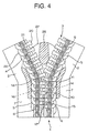
- a slide fastener according to a fourth embodiment of the invention shown in FIG. 7 concerns the end stop 10 for the slider as the top end stop 12 formed at an end portion of a coil type fastener stringer 2.
- the rod-like body 14 of a predetermined length formed of a mono-filament of the same material as the coil-like fastener element 5 is inserted into the coupling space portion 23 existing at a top end portion of the fastener stringer 12, that is, for example, as shown in FIG.
- top end stop 12 may be provided on both the right and left fastener stringers 2, it is permissible to provide it on the fastener stringer 2 of one side.
- the top end stop 12 is formed such that the coupling head 20 of the mating fastener element 4 to be meshed with is incapable of invading in between the coupling heads 20 on the end stop 10 side. Because in the non-fusing portion 16 of the top end stop 12 completed, the sewing yarn 8 is not deteriorated as it is not heated, the coil-type fastener elements 5 are fixed firmly. In addition, in the fused portion 15, the coil type fastener elements 5 and the rod-like body 14 are fused and integrated so as to finish a strong and rigid top end stop 12. This top end stop 12 is available effectively as the end stop 10 for the slider.
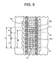
- Fig. 8 and Fig. 9 show the fifth embodiment of this invention.
- the coil type fastener elements 5 in which the rod-like body 14 are inserted is fused with the inner end portion 18 of the rod-like body 14 so as to form the second fused portion 15b.
- the second fused portion 15b prevents the inner end portion 18 of the rod-like body 14 from escaping from the inside of the coil type fastener elements 5 at the time when the slider 27 moves to the location where the slider 27 contacts with the bottom end stop 11, right and left coil type fastener elements 5 are separated, and the coil type fastener elements 5 in the inner end portion 18 side of the bottom end stop 11 are pushed and opened in the right and left directions.
- the second fused portion 15b has the fusing range which includes the portion in which the coil type fastener elements 5 in which the rod-like body 14 is not inserted is fused with the coil type fastener elements 5 in which the rod-like body 14 is inserted. That is, the entire length of bottom end stop 11 is longer than that of rod-like body 14.
- the second fused portion 15b is set the coil type fastener elements 5, in which rod-like body 14 is not inserted, adjacent to the coil type fastener elements 5 in which the rod-like body 14 is inserted in the fusing range, the inner end portion 18 of the rod-like body 14 can be fused with the coil type fastener elements 5 surely within the range of the second fused portion 15b, even if the length of the rod-like body 14 may be different and the rod-like body 14 longer than the predetermined length is inserted into the coil type fastener elements 5.
- the non-fused portion 16 is provided in which coil type fastener elements 5 is not fused with rod-like body 14, which is inserted in the coil type fastener elements 5.
- the rod-like body 14 is not fused with the coil type fastener elements 5 too tightly, and the fused rod-like body 14 and the coil type fastener elements 5 do not become fragile and are not damaged. Further, since the bottom end stop 11 does not become rigid, even if the slider 27 moves toward the bottom end stop 11 and butts the bottom end stop 11, the non-fused portion 16 bends slightly and changes its shape so that it alleviates the impact strength and prevents the damage of bottom end stop 11.
- first fused portion 15a is the longest
- second fused portion 15b is as long as the non-fused portion 16.
- first fused portion 15a is the longest
- non-fused portion 16 is in the second longest
- second fused portion 15b is the shortest.
- the length B of the rod-like body 14 is 7 mm, and the length A of the entire fused portion 15 is 8 mm.
- the length a1 of the first fused portion 15a is 4 mm
- the length a3 of the second fused portion 15b is 2 mm
- the length a2 of non-fused portion 16 is 2 mm.
- the second fused portion 15b is fused with the rod-like body 14 1 mm in length.
- each portion is not limited to above mentioned lengths, and for example, it is permissible that the lengths of the first fused portion 15a and the second fused portion 15b will be same and the length of the non-fused portion 16 is longer than the first fused portion 15a and the second fused portion 15b respectively, and the non-fused portion 16 is permissible to have the same length of the sum of the lengths of the first fused portion 15a and the second fused portion 15b.
- the specific example will be described in that case.
- the length B of the rod-like body 14 is 7mm
- the length A of the entire fused portion 15 is 8 mm
- the length a1 of the first fused portion 15a is 2 mm
- the length a3 of the second fused portion 15b is 2 mm
- the length a2 of the non-fused portion 16 is 4 mm.
- the second fused portion 15b is fused with the rod-like body 14 1 mm in length.
- the length of the entire fused portion is longer than that of the non-fused portion 16, and the length of the non-fused portion 16 is in the range of less than the sum of the lengths of the first fused portion 15a and the second fused portion 15b.
- the fused portion 15, 15a should be made longest, in which the outer end portion 17 of the rod-like body 14 and the linear fastener elements 4 are fused with.
- the fused portion 15,15a is on the location in which the fused portion 15, 15a is lest likely to be loaded, when the slider 27 contact with the bottom end stop 11 and the linear fastener elements 4 adjacent to the bottom end stop 11 is pushed and opened, so that the damage of bottom end stop 11 can be prevented.
- the dimensional relation between the rod-like body 14, the first fused portion 15a and the second fused portion 15b in the width directions thereof is that each width of the first fused portion 15a and the second fused portion 15b is wider than that of the rod-like body 14, and the width of rod-like body 14 is fit within each width of the first fused portion 15a and the second fused portion 15b.
- the diameter that is the width of the rod-like body 14 is 6 mm, while each width of the first fused portion 15a and the second fused portion 15b is 10 mm.
- the rod-like body 14 Since the rod-like body 14 is pushed and changed its shape at the time of fusing with the coil type fastener elements 5, so that its width is wider than that of above mentioned dimension, the rod-like body 14 can be fused with the coil type fastener elements 5 firmly in the wide range in respective fused portions 15a,15b.
- the coil type or the zigzag type linear fastener elements both of which being formed of a mono-filament of polyamide or polyester are mounted on a side edge of the fastener tape so as to complete an ordinary type or hidden type slide fastener.
- a sewing yarn for fastening the fastener elements onto a fastener tape is never cut out due to a load by sliding of the slider and the end portion of the end stop is integrated firmly by fusion.
- the produced end stop does not use any metal and is free of any burr on its surface, particularly, this is suitable and can be employed for a slide fastener for clothing.
Landscapes
- Slide Fasteners (AREA)
- Lining Or Joining Of Plastics Or The Like (AREA)
Abstract
Description
Claims (12)
- An end stop for a slide fastener in which a linear fastener element row (3) of synthetic resin is mounted on a side edge of a fastener tape (7), and a rod-like body (14) of synthetic resin is inserted into a coupling space portion (23) located in an inside of coupling heads (20) in plural fastener elements (4) located at an end of the fastener element row (3) so as to form the end stop (10) for a slider (27),
characterized in that a fused portion (15) is provided by fusing the several fastener elements (4) of the plural fastener elements in which the rod-like body (14)is inserted with the rod-like body (14), and a non-fused portion (16) is formed without fusing the fastener elements (4) of the plural fastener elements in which the rod-like body (14) is inserted except the fastener elements fused with the rod-like body (14) as the fused portion (15) with the rod-like body (14) so as to form the end stop (10). - The end stop for the slide fastener according to claim 1, characterized in that the fused portion (15, 15a) is provided on an outer end portion (17) of the rod-like body (14).
- The end stop for the slide fastener according to claim 2, characterized in that a length of the fused portion (15, 15a) in a longitudinal direction of the rod-like body (14) is in a range of half or less of the length of the rod-like body (14).
- The end stop for the slide fastener according to claim 2, characterized in that a first fused portion (15a) is provided on the outer end portion (17) of the rod-like body (14), a second fused portion (15b) is provided on an inner end portion (18) of the rod-like body (14), and the non-fused portion (16) is provided between the first fused portion (15a) and the second fused portion (15b).
- The end stop for the slide fastener according to claim 4, characterized in that a length of the first fused portion (15a) in a longitudinal direction of the rod-like body (14) is longer than the length of the second fused portion (15b).
- The end stop for the slide fastener according to claim 4, characterized in that a length of the non-fused portion (16) in a longitudinal direction of the rod-like body (14) is in a range of less than a sum of the length of the first fused portion (15a)and the length of the second fused portion (15b).
- The end stop for the slide fastener according to claim 4, characterized in that a length of the first fused portion (15a) in a longitudinal direction of the rod-like body (14) is longer than the length of the second fused portion (15b)and the length of the non-fused portion (16).
- The end stop for the slide fastener according to claim 1, characterized in that the rod-like body (14) is inserted into the linear fastener element row (3) in a separated state so as to form a top end stop (12).
- The end stop for the slide fastener according to claim 1, characterized in that the rod-like body (14) is inserted into the linear fastener element row (3) in a coupled state so as to form a bottom end stop (11).
- The end stop for the slide fastener according to claim 1, characterized in that the linear fastener element row (3) is disposed on the side edge of the fastener tape (7) and sewed with a sewing yarn (8).
- The end stop for the slide fastener according to claim 1, characterized in that the linear fastener element row (3) is formed of coil type fastener elements (5).
- The end stop for the slide fastener according to claim 1, characterized in that the linear fastener element row (3) is formed of zigzag type fastener elements (6).
Applications Claiming Priority (2)
| Application Number | Priority Date | Filing Date | Title |
|---|---|---|---|
| JP2003423416 | 2003-12-19 | ||
| JP2003423416 | 2003-12-19 |
Publications (3)
| Publication Number | Publication Date |
|---|---|
| EP1543739A2 true EP1543739A2 (en) | 2005-06-22 |
| EP1543739A3 EP1543739A3 (en) | 2006-05-17 |
| EP1543739B1 EP1543739B1 (en) | 2015-07-29 |
Family
ID=34510708
Family Applications (1)
| Application Number | Title | Priority Date | Filing Date |
|---|---|---|---|
| EP04029812.7A Expired - Lifetime EP1543739B1 (en) | 2003-12-19 | 2004-12-16 | End stop for slide fastener |
Country Status (8)
| Country | Link |
|---|---|
| US (1) | US7251866B2 (en) |
| EP (1) | EP1543739B1 (en) |
| KR (1) | KR100571970B1 (en) |
| CN (1) | CN100525668C (en) |
| BR (1) | BRPI0405922B1 (en) |
| ES (1) | ES2549655T3 (en) |
| MX (1) | MXPA04012809A (en) |
| TW (1) | TWI243034B (en) |
Cited By (2)
| Publication number | Priority date | Publication date | Assignee | Title |
|---|---|---|---|---|
| EP1745713A1 (en) * | 2005-07-19 | 2007-01-24 | Ykk Corporation | Slide fastener |
| EP2324726A2 (en) | 2009-11-18 | 2011-05-25 | YKK Corporation | Slide fastener |
Families Citing this family (9)
| Publication number | Priority date | Publication date | Assignee | Title |
|---|---|---|---|---|
| JP4062617B2 (en) * | 2003-10-17 | 2008-03-19 | Ykk株式会社 | Top of line slide fastener |
| US9016623B2 (en) * | 2011-11-30 | 2015-04-28 | The Boeing Company | Jam protection and alleviation for control surface linkage mechanisms |
| USD715187S1 (en) * | 2012-03-31 | 2014-10-14 | Ykk Corporation | Chain for slide fastener |
| USD710748S1 (en) * | 2012-06-07 | 2014-08-12 | Ykk Corporation | Chain for slide fastener |
| USD713760S1 (en) * | 2012-06-07 | 2014-09-23 | Ykk Corporation | Chain for slide fastener |
| USD713761S1 (en) * | 2012-06-07 | 2014-09-23 | Ykk Corporation | Chain for slide fastener |
| WO2015151167A1 (en) * | 2014-03-31 | 2015-10-08 | Ykk株式会社 | Concealed slide fastener and bottom stop forming device |
| CN110545689B (en) * | 2017-03-09 | 2022-03-25 | Ykk株式会社 | Product with zipper and method of manufacturing the product with zipper |
| CN109846149A (en) * | 2019-04-01 | 2019-06-07 | 林文静 | A tooth chain belt and a zipper |
Family Cites Families (13)
| Publication number | Priority date | Publication date | Assignee | Title |
|---|---|---|---|---|
| US1794139A (en) * | 1927-05-04 | 1931-02-24 | Mishawaka Rubber & Woolen Mfg | Slider-operated fastener |
| US2398592A (en) * | 1942-05-05 | 1946-04-16 | Davis Marinsky | End stop for flexible stringers |
| US2347426A (en) * | 1943-01-11 | 1944-04-25 | Louis H Morin | Bottom stop for separable fasteners |
| US2423202A (en) * | 1943-07-09 | 1947-07-01 | Davis Marinsky | Pull apart separable fastener |
| US2819504A (en) * | 1952-05-24 | 1958-01-14 | Louis H Morin | Reinforced separable fasteners |
| US3067476A (en) * | 1954-05-18 | 1962-12-11 | Stahlwerk Kabel C Pouplier Jr | Slide fastener |
| US4091509A (en) * | 1976-12-20 | 1978-05-30 | Textron Inc. | Slide fastener with bottom stop |
| DE2937054A1 (en) | 1979-09-13 | 1981-03-19 | Standard Elektrik Lorenz Ag, 7000 Stuttgart | DISPLAY ARRANGEMENT WITH A LIQUID CELL |
| JP3620973B2 (en) * | 1998-09-30 | 2005-02-16 | Ykk株式会社 | Slide fastener fastener |
| CN1254568A (en) | 1998-11-24 | 2000-05-31 | 鱼光亚 | Antalgic rheumatism-treating liquid and its preparing process |
| CN2508603Y (en) * | 2001-11-07 | 2002-09-04 | 魏昌明 | Means for stopping movement of slider at the end |
| JP3708046B2 (en) * | 2001-12-13 | 2005-10-19 | Ykk株式会社 | Slide fastener |
| JP4116827B2 (en) * | 2002-06-20 | 2008-07-09 | Ykk株式会社 | Slide fastener stop |
-
2004
- 2004-12-16 KR KR1020040106780A patent/KR100571970B1/en not_active Expired - Fee Related
- 2004-12-16 ES ES04029812.7T patent/ES2549655T3/en not_active Expired - Lifetime
- 2004-12-16 EP EP04029812.7A patent/EP1543739B1/en not_active Expired - Lifetime
- 2004-12-16 MX MXPA04012809A patent/MXPA04012809A/en active IP Right Grant
- 2004-12-16 US US11/016,646 patent/US7251866B2/en not_active Expired - Lifetime
- 2004-12-17 CN CNB2004101046780A patent/CN100525668C/en not_active Expired - Lifetime
- 2004-12-17 TW TW093139539A patent/TWI243034B/en not_active IP Right Cessation
- 2004-12-17 BR BRPI0405922-0B1A patent/BRPI0405922B1/en not_active IP Right Cessation
Cited By (5)
| Publication number | Priority date | Publication date | Assignee | Title |
|---|---|---|---|---|
| EP1745713A1 (en) * | 2005-07-19 | 2007-01-24 | Ykk Corporation | Slide fastener |
| US7669296B2 (en) | 2005-07-19 | 2010-03-02 | Ykk Corporation | Slide fastener |
| EP2324726A2 (en) | 2009-11-18 | 2011-05-25 | YKK Corporation | Slide fastener |
| US8402613B2 (en) | 2009-11-18 | 2013-03-26 | Ykk Corporation | Slide fastener |
| EP2324726A3 (en) * | 2009-11-18 | 2013-07-10 | YKK Corporation | Slide fastener |
Also Published As
| Publication number | Publication date |
|---|---|
| TW200526142A (en) | 2005-08-16 |
| CN1628570A (en) | 2005-06-22 |
| CN100525668C (en) | 2009-08-12 |
| TWI243034B (en) | 2005-11-11 |
| EP1543739A3 (en) | 2006-05-17 |
| KR20050062397A (en) | 2005-06-23 |
| BRPI0405922B1 (en) | 2013-12-24 |
| ES2549655T3 (en) | 2015-10-30 |
| HK1073766A1 (en) | 2005-10-21 |
| US7251866B2 (en) | 2007-08-07 |
| KR100571970B1 (en) | 2006-04-18 |
| EP1543739B1 (en) | 2015-07-29 |
| BRPI0405922A (en) | 2005-09-06 |
| MXPA04012809A (en) | 2005-06-23 |
| US20050132542A1 (en) | 2005-06-23 |
Similar Documents
| Publication | Publication Date | Title |
|---|---|---|
| US7251866B2 (en) | End stop for slide fastener | |
| US20190357638A1 (en) | Slide Fastener-Attached Product, Element Member and Manufacturing Method of Slide Fastener-Attached Product | |
| US6851162B2 (en) | Concealed type slide fastener with separable bottom end stop | |
| JP3621014B2 (en) | Chain for slide fastener, terminal molding method and terminal molding apparatus | |
| EP1920672B1 (en) | Fastener stringer of concealed type slide fastener | |
| JP4116827B2 (en) | Slide fastener stop | |
| US7137177B2 (en) | Top end stop of linear slide fastener | |
| EP1072209B1 (en) | Linear slide fastener | |
| US7114224B2 (en) | Slide fastener | |
| HK1073766B (en) | End stop for slide fastener | |
| JP2005199056A (en) | Slide fastener stop | |
| JP2008154615A (en) | Stringer for slide fastener | |
| CN121400661A (en) | Zippers and zipper manufacturing methods |
Legal Events
| Date | Code | Title | Description |
|---|---|---|---|
| PUAI | Public reference made under article 153(3) epc to a published international application that has entered the european phase |
Free format text: ORIGINAL CODE: 0009012 |
|
| AK | Designated contracting states |
Kind code of ref document: A2 Designated state(s): AT BE BG CH CY CZ DE DK EE ES FI FR GB GR HU IE IS IT LI LT LU MC NL PL PT RO SE SI SK TR |
|
| AX | Request for extension of the european patent |
Extension state: AL BA HR LV MK YU |
|
| PUAL | Search report despatched |
Free format text: ORIGINAL CODE: 0009013 |
|
| AK | Designated contracting states |
Kind code of ref document: A3 Designated state(s): AT BE BG CH CY CZ DE DK EE ES FI FR GB GR HU IE IS IT LI LT LU MC NL PL PT RO SE SI SK TR |
|
| AX | Request for extension of the european patent |
Extension state: AL BA HR LV MK YU |
|
| RIC1 | Information provided on ipc code assigned before grant |
Ipc: A44B 19/38 20060101AFI20050329BHEP Ipc: A44B 19/36 20060101ALI20060324BHEP |
|
| 17P | Request for examination filed |
Effective date: 20060824 |
|
| AKX | Designation fees paid |
Designated state(s): AT BE BG CH CY CZ DE DK EE ES FI FR GB GR HU IE IS IT LI LT LU MC NL PL PT RO SE SI SK TR |
|
| 17Q | First examination report despatched |
Effective date: 20070529 |
|
| RBV | Designated contracting states (corrected) |
Designated state(s): DE ES FR GB IT |
|
| GRAP | Despatch of communication of intention to grant a patent |
Free format text: ORIGINAL CODE: EPIDOSNIGR1 |
|
| INTG | Intention to grant announced |
Effective date: 20150316 |
|
| GRAS | Grant fee paid |
Free format text: ORIGINAL CODE: EPIDOSNIGR3 |
|
| GRAA | (expected) grant |
Free format text: ORIGINAL CODE: 0009210 |
|
| AK | Designated contracting states |
Kind code of ref document: B1 Designated state(s): DE ES FR GB IT |
|
| REG | Reference to a national code |
Ref country code: GB Ref legal event code: FG4D |
|
| REG | Reference to a national code |
Ref country code: DE Ref legal event code: R096 Ref document number: 602004047559 Country of ref document: DE |
|
| REG | Reference to a national code |
Ref country code: ES Ref legal event code: FG2A Ref document number: 2549655 Country of ref document: ES Kind code of ref document: T3 Effective date: 20151030 |
|
| REG | Reference to a national code |
Ref country code: FR Ref legal event code: PLFP Year of fee payment: 12 |
|
| REG | Reference to a national code |
Ref country code: DE Ref legal event code: R097 Ref document number: 602004047559 Country of ref document: DE |
|
| PLBE | No opposition filed within time limit |
Free format text: ORIGINAL CODE: 0009261 |
|
| STAA | Information on the status of an ep patent application or granted ep patent |
Free format text: STATUS: NO OPPOSITION FILED WITHIN TIME LIMIT |
|
| 26N | No opposition filed |
Effective date: 20160502 |
|
| REG | Reference to a national code |
Ref country code: FR Ref legal event code: PLFP Year of fee payment: 13 |
|
| REG | Reference to a national code |
Ref country code: FR Ref legal event code: PLFP Year of fee payment: 14 |
|
| PGFP | Annual fee paid to national office [announced via postgrant information from national office to epo] |
Ref country code: DE Payment date: 20191203 Year of fee payment: 16 |
|
| PGFP | Annual fee paid to national office [announced via postgrant information from national office to epo] |
Ref country code: IT Payment date: 20191209 Year of fee payment: 16 Ref country code: FR Payment date: 20191115 Year of fee payment: 16 |
|
| PGFP | Annual fee paid to national office [announced via postgrant information from national office to epo] |
Ref country code: GB Payment date: 20191213 Year of fee payment: 16 Ref country code: ES Payment date: 20200102 Year of fee payment: 16 |
|
| REG | Reference to a national code |
Ref country code: DE Ref legal event code: R119 Ref document number: 602004047559 Country of ref document: DE |
|
| GBPC | Gb: european patent ceased through non-payment of renewal fee |
Effective date: 20201216 |
|
| PG25 | Lapsed in a contracting state [announced via postgrant information from national office to epo] |
Ref country code: IT Free format text: LAPSE BECAUSE OF NON-PAYMENT OF DUE FEES Effective date: 20201216 Ref country code: FR Free format text: LAPSE BECAUSE OF NON-PAYMENT OF DUE FEES Effective date: 20201231 |
|
| PG25 | Lapsed in a contracting state [announced via postgrant information from national office to epo] |
Ref country code: DE Free format text: LAPSE BECAUSE OF NON-PAYMENT OF DUE FEES Effective date: 20210701 Ref country code: GB Free format text: LAPSE BECAUSE OF NON-PAYMENT OF DUE FEES Effective date: 20201216 |
|
| REG | Reference to a national code |
Ref country code: ES Ref legal event code: FD2A Effective date: 20220221 |
|
| PG25 | Lapsed in a contracting state [announced via postgrant information from national office to epo] |
Ref country code: ES Free format text: LAPSE BECAUSE OF NON-PAYMENT OF DUE FEES Effective date: 20201217 |