EP1543206B1 - Swimming pool cleaning apparatus - Google Patents
Swimming pool cleaning apparatus Download PDFInfo
- Publication number
- EP1543206B1 EP1543206B1 EP20030764706 EP03764706A EP1543206B1 EP 1543206 B1 EP1543206 B1 EP 1543206B1 EP 20030764706 EP20030764706 EP 20030764706 EP 03764706 A EP03764706 A EP 03764706A EP 1543206 B1 EP1543206 B1 EP 1543206B1
- Authority
- EP
- European Patent Office
- Prior art keywords
- valve
- flow
- cleaned
- fluid
- wall
- Prior art date
- Legal status (The legal status is an assumption and is not a legal conclusion. Google has not performed a legal analysis and makes no representation as to the accuracy of the status listed.)
- Expired - Lifetime
Links
- 238000004140 cleaning Methods 0.000 title claims description 9
- 230000009182 swimming Effects 0.000 title description 13
- 239000012530 fluid Substances 0.000 claims description 24
- 210000002105 tongue Anatomy 0.000 claims description 12
- 230000003014 reinforcing effect Effects 0.000 claims description 6
- 230000010355 oscillation Effects 0.000 claims description 4
- 230000002093 peripheral effect Effects 0.000 claims description 4
- 238000011144 upstream manufacturing Methods 0.000 claims 1
- 238000005192 partition Methods 0.000 description 10
- 239000007788 liquid Substances 0.000 description 3
- 230000009977 dual effect Effects 0.000 description 2
- 230000002708 enhancing effect Effects 0.000 description 2
- 241000209094 Oryza Species 0.000 description 1
- 235000007164 Oryza sativa Nutrition 0.000 description 1
- 230000003467 diminishing effect Effects 0.000 description 1
- 230000001939 inductive effect Effects 0.000 description 1
- 238000009434 installation Methods 0.000 description 1
- 238000012986 modification Methods 0.000 description 1
- 230000004048 modification Effects 0.000 description 1
- 238000009877 rendering Methods 0.000 description 1
- 235000009566 rice Nutrition 0.000 description 1
- 238000005096 rolling process Methods 0.000 description 1
- 230000035939 shock Effects 0.000 description 1
Images


Classifications
-
- E—FIXED CONSTRUCTIONS
- E04—BUILDING
- E04H—BUILDINGS OR LIKE STRUCTURES FOR PARTICULAR PURPOSES; SWIMMING OR SPLASH BATHS OR POOLS; MASTS; FENCING; TENTS OR CANOPIES, IN GENERAL
- E04H4/00—Swimming or splash baths or pools
- E04H4/14—Parts, details or accessories not otherwise provided for
- E04H4/16—Parts, details or accessories not otherwise provided for specially adapted for cleaning
- E04H4/1654—Self-propelled cleaners
- E04H4/1663—Self-propelled cleaners the propulsion resulting from an intermittent interruption of the waterflow through the cleaner
-
- Y—GENERAL TAGGING OF NEW TECHNOLOGICAL DEVELOPMENTS; GENERAL TAGGING OF CROSS-SECTIONAL TECHNOLOGIES SPANNING OVER SEVERAL SECTIONS OF THE IPC; TECHNICAL SUBJECTS COVERED BY FORMER USPC CROSS-REFERENCE ART COLLECTIONS [XRACs] AND DIGESTS
- Y10—TECHNICAL SUBJECTS COVERED BY FORMER USPC
- Y10T—TECHNICAL SUBJECTS COVERED BY FORMER US CLASSIFICATION
- Y10T137/00—Fluid handling
- Y10T137/7722—Line condition change responsive valves
- Y10T137/7781—With separate connected fluid reactor surface
Definitions
- the present invention generally relates to self propelled swimming pool cleaners for cleaning submerged surfaces, and more particularly to a swimming pool cleaning apparatus incorporating a flow control valve for establishing intermittent flow of a fluid through the cleaner for causing the cleaner to travel across the surface to be cleaned.
- Submersible pool cleaners employing oscillating valves within a housing and flexible discs engaging the surface to be cleaned are generally well known, as illustrated by way of example with reference to U.S. Patent Nos. 4,023,227 to Chauvier and 4,351,077 to Hofmann .
- Chauvier discloses an swimming pool surface cleaning apparatus having two suction passages in suction communication with a cleaning head that is releasably engageable with the surface to be cleaned and a flapper valve for automatically transferring the flow of liquid from one passage to the other. As the flow of liquid in a passage is halted, the kinetic energy of the liquid is transferred to the apparatus, causing it to be displaced along the surface and randomly migrate across the surface for cleaning it.
- Hoffman discloses a cleaning apparatus having an annular flexible disc located at the inlet end of the suction head surrounding a central opening below the flexible disc and a transverse inlet opening to the passage through the suction head located above and adjacent the flexible disc.
- the transverse inlet opening is substantially symmetrical about the direction of movement of the head and faces in the general direction towards which the head moves in operation.
- An upper member held in spaced relation relative to the disc is provided to define a flow path between it and the disc towards the transverse inlet opening.
- US Patent Nos. 5,465,443 to Rice et al. and 6,122,794 to Atkins disclose swimming pool cleaner components with Rice disclosing discs and a footpad for an automatic swimming pool cleaners having upwardly-extending, non-truncated fins protruding radially from their peripheries.
- the peripheries themselves define a plurality of tongues inducing ramped segments facilitating movement over obstacles extending from swimming pool surfaces.
- discs having a series of slits spaced along portions of their peripheries. The slits permit an effective surface area to increase as the associated cleaner climbs a side of a swimming pool, enhancing the maneuverability of the cleaner.
- Atkins discloses a foot and disc for a swimming pool cleaner with the disc having tapering holes at spaced intervals and an edge of the disc serrated. Short upstanding and outwardly projecting fins extend from apices of the serrations.
- a dual valve pulsating submersible pool cleaner is known from US-A-566246 .
- Embodiments of the present invention herein described provide an efficiently run submersible cleaner which includes components that are easily replaceable by the consumer.
- a submersible cleaner in keeping with the teachings of the present invention may include a housing moveable along a submerged surface to be cleaned through fluid flow past a valve operable for moving the cleaner.
- the housing may include a flow passage for a flow of fluid and debris from an inlet to an outlet with the fluid and debris constrained to flow through an opening defined within the passage.
- a wall may extend into the flow passage for defining the opening.
- a valve may be operable within the flow passage for interrupting fluid flow.
- a retractable element may be moveable between the valve and the wall for reducing a gap formed between them. The retractable element may be attached to either the valve or the wall, and may make slidable engagement.
- a flexible plate may be carried proximate the inlet for engaging the surface to be cleaned.
- the flexible plate may be described to include an upper surface, an opposing lower surface for contacting the surface to be cleaned, and a periphery defined by a plurality of tongues radially extending about the periphery.
- Each of the plurality of tongues may include a lower surface portion for contacting the surface to be cleaned and a contouring portion in a spaced relation with the surface to be cleaned during operation of the apparatus, thus upwardly lifting an outer most periphery of the plate from the surface to be cleaned.
- a plurality of reinforcing elements may be integrally formed with the flexible plate for upwardly contouring the periphery from the surface to be cleaned.
- the reinforcing elements may include a rib that may be integrally formed with the upper surface of the flexible plate with the rib extending radially outward while confined within the periphery of the flexible plate.
- the reinforcing element may comprise a flange extending along the peripheral edge of the tongue, or yet other reinforcing styled elements.
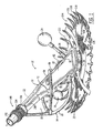
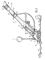
- an embodiment of the present invention is herein described, by way of example, for a submersible swimming pool cleaner 10 having a housing 12 inclined toward a direction of travel, which housing carries a bumper 14 and weight 16 about a forward portion 18 with the bumper extending to left and right side portions 20, 22.
- a float 24 is carried at an aft portion 26 for acting in conjunction with the weight 16 in allowing the cleaner 10 to fall to an upright position when dropping from a sidewall of a swimming pool.
- Vertical and horizontal bumper members 28, 30 are effective in having the cleaner avoid obstructions within the swimming pool, such as steps and sharp corners.
- the housing 12 further carries a flexible plate 32 via attachment with a footpad 34.
- the housing 12 includes a single flow passage 36 extending from an inlet 38 to an outlet 40 for a flow of fluid and debris through the passage, as described with reference to FIG. 3 .
- a partition wall 42 extends into the single flow passage 36 such that the flow of fluid and debris (illustrated with arrows 44 ) are constrained to pass through an opening 46 formed thereby and pass to the outlet 40, which outlet is adapted for connection to a suction source 48.
- the flexible plate 32 is carried about the inlet 38 for engaging a submerged surface 50 to be cleaned.
- a valve 52 is pivotally carried within the flow passage 36 for interrupting fluid flow 44 through the passage during an oscillation of the valve between a seated position 54 for interrupting the flow to an unseated position 56 permitting the flow, as illustrated with reference to FIGS.
- the valve 52 interrupts flow through the passage 36 resulting in a motion of the inclined housing 12 causing it to travel along the surface of the pool to be cleaned, the valve thus acting as the "motor" for the pool cleaner.
- a suction of the fluid through the flow passage 36 causes an oscillating of the valve between the seated and the unseated positions and a resulting movement of the cleaner 10 across the submerged surface 50.
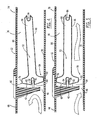
- a retractable element 58 is moveable between a valve distal end 60 and a surface 62 of the partition wall 42 for reducing a gap 64 formed between them, thus substantially limiting the flow of the fluid and debris to only one side 66 of the valve 52.
- the retractable element 58 may be dimensioned such that the fluid flow through the passage 36 causes the retractable element to have slidably engagement between the valve distal end 60 and the surface 62 of the partition wall 42 during the oscillation of the valve, as illustrated with reference again to FIGS. 4 and 5 , or alternatively may fully close or simply reduce the size of the gap 64, as illustrated with reference to FIG. 6 .
- the single flow passage 36 may be defined by opposing top and bottom walls 68, 70 in combination with opposing left and right sidewalls 72, 74, wherein the distal end 60 of the valve 52 contacts the bottom wall 70 in the seated position 54 and oscillates between the seated position and a stop 76 formed with the distal end 60 for contacting the top wall 68.
- an access opening 78 within the top wall 68 provides entry into the housing 12 and the flow passage 36.
- a detachable cover 80 encloses the opening 78. Access to the flow passage provides a convenience when clearing out debris lodged therein or replacing the valve, by way of example.
- the partition wall 42 is integrally formed with the cover 80, as further illustrated with reference to FIG. 7 .
- the cover 80 includes a lock 82 and tab 84 located at ends of the cover for securing the cover to the housing 12 for covering the opening 78.
- a pivot pin 86 is carried by the housing 12 for pivotal connection with a proximal end 88 of the valve 52.
- the valve 52 may be constructed to include an elongate arm 90 having the proximal end 88 for connection to the pivot pin 86.
- a head portion 92 is located at the valve distal end 60. The distal end 60 is carried within the passage 36 downstream the proximal end 88.
- the head portion 92 includes a slot 94 for slidably receiving the retractable element 58.
- One embodiment of the retractable element 58 includes a slit 96 that is operable with a pin 98 carried within the slot 94, as illustrated with reference to FIGS. 8 and 9 .
- Flexible side edges 100 extend along the longitudinal sides of the valve 52 for minimizing side gaps 102 on the sides of the valve and for providing a close fit, as further illustrated with reference to FIG. 10 , thus enhancing control of the fluid flow along the one side 66 of the valve 52, as earlier described with reference to FIGS. 3-5 .
- the head portion 92 having a protrusion 104 extending radially outward from the valve distal end 60 for slidably receiving the retractable element 58, as illustrated with to reference to FIG. 11 .
- the partition wall 42 may include a slot 106 extending for slidably receiving the retractable element 58 , as illustrated with reference to FIG. 12 .
- the partition wall 42 may include a protrusion 108 extending outward toward the valve 52 for slidably receiving the retractable element 58, as illustrated by way of further example with reference to FIG. 11A .
- the retractable element 58 may have various shapes and may be attached to the valve 52 or to the partition wall 42 without deviating from the teachings of the present invention, and may or may not fully close the gap 64, as illustrated with reference to FIGS. 13-20 .
- the generally circular cross sectional shape of the retractable element 58 and carried within a generally arcuate shape for the slot 94 supports a rolling motion for the retractable element during movement of the head portion 92, thus reducing wear of the surface and element while remaining effective in directing fluid flow to the one side 66 of the valve 52.
- the retractable element 58 is movably carried within the slot 94 making continuous contact with the 62 of the partition wall 42 or in close proximity as herein described.
- an embodiment of the valve 52 includes the head portion 92 having an angled slot 94 tapering from outside toward a slotted hole 95, or alternatively having the tapered slot within the partition wall as illustrated with reference to FIG. 18 .
- the head contact element includes an elongate portion having one end extending out of the slot 94 and an opposing end having a bulbous portion for a sliding movement within the hole 95.
- a flexible arm portion 109 may be provided as a shock buffer that results in reducing noise generated by the oscillating valve 52, as illustrated with reference again to FIG. 6 .
- the flexible plate 32 may be described as having an upper surface 110 and an opposing lower surface 112 for contacting the surface to be cleaned 50.
- a periphery 114 of the plate 32 includes a plurality of tongues 116 radially extending thereabout.
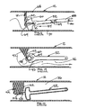
- Each tongue 116 includes a lower surface portion 118 for contacting the surface to be cleaned 50 and a contoured portion 120 in a spaced relation with the surface to be cleaned during operation of the cleaner 10, as illustrated with reference again to FIG. 3 , and to FIGS. 21 and 22 , the outer most peripheral portion of the plate being upwardly lifted from the surface to be cleaned.
- a rib 122 is integrally formed with the upper surface 110 of the flexible plate 32 at the tongue 116.
- the rib 122 reinforces the tongue 116 for securing the contoured portion 120 in the convex shape.
- Alternate reinforcing element shapes may be formed with the flexible plate 32 for upwardly contouring the periphery 114 upwardly from the surface to be cleaned 50, including a flange 124 extending along a peripheral edge of the tongue, as illustrated by way of example with reference to FIGS. 23 and 24 .
- embodiments of the plate 32 may include slots 126 radially extending from a center 128 of the plate.
- the slot 126 herein described is tapered so as to provide a diminishing gap as the taper extends radially outward from the center 128.
- the plate 32 may include a slit 130, as illustrated with reference again to FIGS. 22 and 24 .
- a combination of tapered slot 126 and slit 130 may be formed within the plate 32, as illustrated with reference to FIG. 26 , such slots and slits extending radially outward from the center 128 of the plate 32 provide added flexibility to the flexible plate 32 and improved maneuverability over contours within the surface to be cleaned 50.
- a plurality of slots or-slit may be symmetrically located as herein illustrated or located as desired for surface conditions.
- the plurality of slots may extend along a first imaginary line 132 centrally positioned between second imaginary lines 134 passing centrally through each of the plurality of tongues 116.
- the plate 32 may include grooves 136 within the lower surface 112 and extending radially outward for the center 128. As illustrated, the grooves 136 may extend only partially between the center 128 and the periphery 114 of the plate 32.
- Pleats 138 provide yet another alternative for adding flexibility to the plate 32, as illustrated with reference FIGS. 27-29 .
- Each of a plurality of pleats 138 extending radially from the center 128 forms a groove 140 within the lower surface 112 and a protrusion 142 in the upper surface 110.
- the plate 32 may include a plurality of holes 144 extending from the upper surface 110 to the lower surface 112 for modifying a suction provided by the flexible plate during operation of the cleaner 10 with the suction source.
- the cleaner 10 herein described by way of example includes a foot pad 34 which carries the plate 32.
- the foot pad 34 is attached to a flange 146 at the inlet 38 of the housing 12 as further illustrated with reference to FIG. 30 .
- the footpad 34 is attached to the housing 12 and the flexible plate 32, and easily replaced by the consumer.
- fluid flow passes through openings within the footpad above the plate and below for providing an effective cleaning of debris from the surface to be cleaned.
- a hose connector 148 is carried at the outlet 40 of the housing 12. Under the influence of the vacuum source 48, typically a pump, a flexible hose 150 connected to the connector 148 causes fluid and debris to flow through the housing 12.
- one embodiment of the hose connector 148 includes a swivel portion 152, nut portion 154 and collar 156 for providing a swivel connection to the hose 150. Such a combination permits easy replacement of parts.
- a key 158 is carried by the collar 156 to fix the bumper 14 in a forward position.
Landscapes
- Engineering & Computer Science (AREA)
- Architecture (AREA)
- Civil Engineering (AREA)
- Structural Engineering (AREA)
- Cleaning In General (AREA)
- Lift Valve (AREA)
- Nozzles For Electric Vacuum Cleaners (AREA)
Description
- The present invention generally relates to self propelled swimming pool cleaners for cleaning submerged surfaces, and more particularly to a swimming pool cleaning apparatus incorporating a flow control valve for establishing intermittent flow of a fluid through the cleaner for causing the cleaner to travel across the surface to be cleaned.
- Submersible pool cleaners employing oscillating valves within a housing and flexible discs engaging the surface to be cleaned are generally well known, as illustrated by way of example with reference to
U.S. Patent Nos. 4,023,227 to Chauvier and4,351,077 to Hofmann . Chauvier discloses an swimming pool surface cleaning apparatus having two suction passages in suction communication with a cleaning head that is releasably engageable with the surface to be cleaned and a flapper valve for automatically transferring the flow of liquid from one passage to the other. As the flow of liquid in a passage is halted, the kinetic energy of the liquid is transferred to the apparatus, causing it to be displaced along the surface and randomly migrate across the surface for cleaning it. Hoffman discloses a cleaning apparatus having an annular flexible disc located at the inlet end of the suction head surrounding a central opening below the flexible disc and a transverse inlet opening to the passage through the suction head located above and adjacent the flexible disc. The transverse inlet opening is substantially symmetrical about the direction of movement of the head and faces in the general direction towards which the head moves in operation. An upper member held in spaced relation relative to the disc is provided to define a flow path between it and the disc towards the transverse inlet opening. - Yet further,
US Patent Nos. 5,465,443 to Rice et al. and6,122,794 to Atkins disclose swimming pool cleaner components with Rice disclosing discs and a footpad for an automatic swimming pool cleaners having upwardly-extending, non-truncated fins protruding radially from their peripheries. The peripheries themselves define a plurality of tongues inducing ramped segments facilitating movement over obstacles extending from swimming pool surfaces. Also disclosed are discs having a series of slits spaced along portions of their peripheries. The slits permit an effective surface area to increase as the associated cleaner climbs a side of a swimming pool, enhancing the maneuverability of the cleaner. By contrast; portions of the cap seal without slits present in the disc provide adequate suction for the disc against the pool surface. Atkins discloses a foot and disc for a swimming pool cleaner with the disc having tapering holes at spaced intervals and an edge of the disc serrated. Short upstanding and outwardly projecting fins extend from apices of the serrations. - A dual valve pulsating submersible pool cleaner is known from
US-A-566246 . - An apparatus according to the pre-charactering part of claim is known from
US-A-6311353 . In this prior art apparatus, a flexible portion is required to be attached between the valve and a chamber wall. - What is also generally known are the problems associated with debris clogging fluid flow passages, wearing cleaner components rendering the cleaner ineffective or unusable, and the difficulty for a consumer attempting to replace such worn components. Embodiments of the present invention herein described provide an efficiently run submersible cleaner which includes components that are easily replaceable by the consumer.
- A submersible cleaner in keeping with the teachings of the present invention may include a housing moveable along a submerged surface to be cleaned through fluid flow past a valve operable for moving the cleaner. The housing may include a flow passage for a flow of fluid and debris from an inlet to an outlet with the fluid and debris constrained to flow through an opening defined within the passage. A wall may extend into the flow passage for defining the opening. A valve may be operable within the flow passage for interrupting fluid flow. A retractable element may be moveable between the valve and the wall for reducing a gap formed between them. The retractable element may be attached to either the valve or the wall, and may make slidable engagement.
- A flexible plate may be carried proximate the inlet for engaging the surface to be cleaned. The flexible plate may be described to include an upper surface, an opposing lower surface for contacting the surface to be cleaned, and a periphery defined by a plurality of tongues radially extending about the periphery. Each of the plurality of tongues may include a lower surface portion for contacting the surface to be cleaned and a contouring portion in a spaced relation with the surface to be cleaned during operation of the apparatus, thus upwardly lifting an outer most periphery of the plate from the surface to be cleaned. A plurality of reinforcing elements may be integrally formed with the flexible plate for upwardly contouring the periphery from the surface to be cleaned. The reinforcing elements may include a rib that may be integrally formed with the upper surface of the flexible plate with the rib extending radially outward while confined within the periphery of the flexible plate. Alternatively, the reinforcing element may comprise a flange extending along the peripheral edge of the tongue, or yet other reinforcing styled elements.
- Embodiments of the invention are described by way of example with reference to the accompanying drawings in which:
-
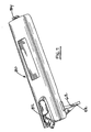
FIG. 1 is a left side perspective view of one embodiment of a swimming pool cleaner according to the present invention; -
FIG. 2 is a right side elevation view of the cleaner ofFIG. 1 ; -
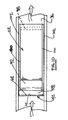
FIG. 3 is a partial cross section view of a pool cleaner illustrating fluid flow therethrough; -
FIGS. 4 and 5 are partial cross section view of a housing portion of the embodiment ofFIG. 3 illustrating an enlarged view of the oscillator valve in a seated position and an unseated position, respectively; -
FIGS. 6 is an alternate embodiment of the valve in keeping with the teachings of the present invention; -
FIG. 7 is a perspective view of a cover; -
FIGS. 8 and 9 are perspective and side views of an embodiment of a valve; -
FIG. 10 is a partial top view looking down on the valve carried within the housing; -
FIG. 11 and11A illustrate alternate embodiments having a retractable element carried by the valve and alternatively by a partition wall, respectively; -
FIGS. 13-20 illustrate alternate embodiments of the valve operable with the retractable element; -
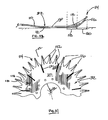
FIG. 21 is a partial top view of one embodiment of a flexible plate; -
FIG. 22 is a partial cross section elevation view taken through lines 22-22 ofFIG. 21 ; -
FIG. 23 is a partial top view of one embodiment of a flexible plate; -
FIG. 24 is a partial cross section elevation view taken through lines 24-24 of FIG.-23; -
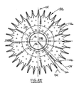
FIG. 25 is a top plan view of one embodiment of a flexible plate; -
FIG. 26 is a top plan view of an alternate embodiment of a flexible plate; -
FIG. 27 is a partial top view of one embodiment of a flexible plate; -
FIG. 28 is a partial cross section elevation view taken through lines 28-28 ofFIG. 27 ; -
FIG. 29 is a partial cross section view taken through lines 29-29 ofFIG. 27 ; -
FIG. 30 is an elevation and partial cross section view of a footpad ofFIG. 1 ; -
FIG. 31 is a side elevation and partial cross section view of the footpad ofFIG. 30 illustrating front and rear lateral inlet ports; and -
FIG. 32 is an elevation view of the footpad ofFIG. 30 illustrating dual lateral inlet ports. - Embodiments of the present invention will now be described more fully with reference to the accompanying drawings. It will be understood by those skilled in the art that this invention may be embodied in many different forms and should not be construed as limited to the embodiments set forth herein. Rather, these embodiments are provided so that this disclosure will be thorough and complete, and will fully convey the scope of the invention to those skilled in the art. Like numerals refer to like elements.
- With reference initially to
FIGS. 1 and2 , an embodiment of the present invention is herein described, by way of example, for a submersibleswimming pool cleaner 10 having ahousing 12 inclined toward a direction of travel, which housing carries abumper 14 andweight 16 about aforward portion 18 with the bumper extending to left andright side portions float 24 is carried at anaft portion 26 for acting in conjunction with theweight 16 in allowing thecleaner 10 to fall to an upright position when dropping from a sidewall of a swimming pool. Vertical andhorizontal bumper members housing 12 further carries aflexible plate 32 via attachment with afootpad 34. - The
housing 12 includes asingle flow passage 36 extending from aninlet 38 to anoutlet 40 for a flow of fluid and debris through the passage, as described with reference toFIG. 3 . Apartition wall 42 extends into thesingle flow passage 36 such that the flow of fluid and debris (illustrated with arrows 44) are constrained to pass through anopening 46 formed thereby and pass to theoutlet 40, which outlet is adapted for connection to asuction source 48. Theflexible plate 32 is carried about theinlet 38 for engaging a submerged surface 50 to be cleaned. Avalve 52 is pivotally carried within theflow passage 36 for interruptingfluid flow 44 through the passage during an oscillation of the valve between aseated position 54 for interrupting the flow to an unseatedposition 56 permitting the flow, as illustrated with reference toFIGS. 4 and 5 . Thevalve 52 interrupts flow through thepassage 36 resulting in a motion of theinclined housing 12 causing it to travel along the surface of the pool to be cleaned, the valve thus acting as the "motor" for the pool cleaner. With continued reference toFIG. 3 , a suction of the fluid through theflow passage 36 causes an oscillating of the valve between the seated and the unseated positions and a resulting movement of the cleaner 10 across the submerged surface 50. - With continued reference to
FIGS. 3-5 , aretractable element 58 is moveable between a valvedistal end 60 and asurface 62 of thepartition wall 42 for reducing agap 64 formed between them, thus substantially limiting the flow of the fluid and debris to only oneside 66 of thevalve 52. Theretractable element 58 may be dimensioned such that the fluid flow through thepassage 36 causes the retractable element to have slidably engagement between the valvedistal end 60 and thesurface 62 of thepartition wall 42 during the oscillation of the valve, as illustrated with reference again toFIGS. 4 and 5 , or alternatively may fully close or simply reduce the size of thegap 64, as illustrated with reference toFIG. 6 . - With reference again to
FIGS. 1-5 , thesingle flow passage 36 may be defined by opposing top andbottom walls right sidewalls 72, 74, wherein thedistal end 60 of thevalve 52 contacts thebottom wall 70 in the seatedposition 54 and oscillates between the seated position and astop 76 formed with thedistal end 60 for contacting thetop wall 68. - As illustrated with reference again to
FIGS. 1-5 , an access opening 78 within thetop wall 68 provides entry into thehousing 12 and theflow passage 36. Adetachable cover 80 encloses theopening 78. Access to the flow passage provides a convenience when clearing out debris lodged therein or replacing the valve, by way of example. In one embodiment of the cleaner, as herein described by way of example, thepartition wall 42 is integrally formed with thecover 80, as further illustrated with reference toFIG. 7 . Thecover 80 includes alock 82 andtab 84 located at ends of the cover for securing the cover to thehousing 12 for covering theopening 78. Apivot pin 86 is carried by thehousing 12 for pivotal connection with aproximal end 88 of thevalve 52. As illustrated with reference again topFIGS. 4 and 5 , thevalve 52 may be constructed to include anelongate arm 90 having theproximal end 88 for connection to thepivot pin 86. Ahead portion 92 is located at the valvedistal end 60. Thedistal end 60 is carried within thepassage 36 downstream theproximal end 88. In the embodiment illustrated with reference toFIGS. 4 and 5 , by way of example, thehead portion 92 includes aslot 94 for slidably receiving theretractable element 58. One embodiment of theretractable element 58 includes aslit 96 that is operable with apin 98 carried within theslot 94, as illustrated with reference toFIGS. 8 and 9 . Flexible side edges 100 extend along the longitudinal sides of thevalve 52 for minimizingside gaps 102 on the sides of the valve and for providing a close fit, as further illustrated with reference toFIG. 10 , thus enhancing control of the fluid flow along the oneside 66 of thevalve 52, as earlier described with reference toFIGS. 3-5 . - Alternate embodiments keeping within the teachings of the present invention, may include by way of example, the
head portion 92 having aprotrusion 104 extending radially outward from the valvedistal end 60 for slidably receiving theretractable element 58, as illustrated with to reference toFIG. 11 . Further, thepartition wall 42 may include a slot 106 extending for slidably receiving theretractable element 58, as illustrated with reference toFIG. 12 . Yet further, thepartition wall 42 may include a protrusion 108 extending outward toward thevalve 52 for slidably receiving theretractable element 58, as illustrated by way of further example with reference toFIG. 11A . As herein illustrated, theretractable element 58 may have various shapes and may be attached to thevalve 52 or to thepartition wall 42 without deviating from the teachings of the present invention, and may or may not fully close thegap 64, as illustrated with reference toFIGS. 13-20 . - With reference to
FIGS. 19 and20 , by way of example, the generally circular cross sectional shape of theretractable element 58 and carried within a generally arcuate shape for theslot 94 supports a rolling motion for the retractable element during movement of thehead portion 92, thus reducing wear of the surface and element while remaining effective in directing fluid flow to the oneside 66 of thevalve 52. Theretractable element 58 is movably carried within theslot 94 making continuous contact with the 62 of thepartition wall 42 or in close proximity as herein described. With reference again toFIGS. 6, 12 , and17 , an embodiment of thevalve 52 includes thehead portion 92 having anangled slot 94 tapering from outside toward a slottedhole 95, or alternatively having the tapered slot within the partition wall as illustrated with reference toFIG. 18 . The head contact element includes an elongate portion having one end extending out of theslot 94 and an opposing end having a bulbous portion for a sliding movement within thehole 95. Such an embodiment allows theretractable element 58 to be secured within theslot 94 during installation and easily held therein during assembly of the valve. Further, aflexible arm portion 109 may be provided as a shock buffer that results in reducing noise generated by the oscillatingvalve 52, as illustrated with reference again toFIG. 6 . - With reference again to
FIGS. 1-3 , theflexible plate 32 may be described as having anupper surface 110 and an opposinglower surface 112 for contacting the surface to be cleaned 50. Aperiphery 114 of theplate 32 includes a plurality oftongues 116 radially extending thereabout. Eachtongue 116 includes alower surface portion 118 for contacting the surface to be cleaned 50 and acontoured portion 120 in a spaced relation with the surface to be cleaned during operation of the cleaner 10, as illustrated with reference again toFIG. 3 , and toFIGS. 21 and 22 , the outer most peripheral portion of the plate being upwardly lifted from the surface to be cleaned. In one embodiment, as herein illustrated, arib 122 is integrally formed with theupper surface 110 of theflexible plate 32 at thetongue 116. Therib 122 reinforces thetongue 116 for securing the contouredportion 120 in the convex shape. Alternate reinforcing element shapes may be formed with theflexible plate 32 for upwardly contouring theperiphery 114 upwardly from the surface to be cleaned 50, including aflange 124 extending along a peripheral edge of the tongue, as illustrated by way of example with reference toFIGS. 23 and 24 . - As illustrates with reference again to
FIG. 2 and toFIG. 25 , embodiments of theplate 32 may includeslots 126 radially extending from acenter 128 of the plate. Theslot 126 herein described is tapered so as to provide a diminishing gap as the taper extends radially outward from thecenter 128. Alternatively, theplate 32 may include aslit 130, as illustrated with reference again toFIGS. 22 and24 . Yet further, a combination of taperedslot 126 and slit 130 may be formed within theplate 32, as illustrated with reference toFIG. 26 , such slots and slits extending radially outward from thecenter 128 of theplate 32 provide added flexibility to theflexible plate 32 and improved maneuverability over contours within the surface to be cleaned 50. A plurality of slots or-slit may be symmetrically located as herein illustrated or located as desired for surface conditions. - By way of further example, and as illustrated with reference again to
FIG. 25 , the plurality of slots may extend along a firstimaginary line 132 centrally positioned between secondimaginary lines 134 passing centrally through each of the plurality oftongues 116. Further, theplate 32 may includegrooves 136 within thelower surface 112 and extending radially outward for thecenter 128. As illustrated, thegrooves 136 may extend only partially between thecenter 128 and theperiphery 114 of theplate 32. -
Pleats 138 provide yet another alternative for adding flexibility to theplate 32, as illustrated with referenceFIGS. 27-29 . Each of a plurality ofpleats 138 extending radially from thecenter 128 forms agroove 140 within thelower surface 112 and aprotrusion 142 in theupper surface 110. - With reference to
FIG. 26 , by way of example, theplate 32 may include a plurality ofholes 144 extending from theupper surface 110 to thelower surface 112 for modifying a suction provided by the flexible plate during operation of the cleaner 10 with the suction source. - As earlier described with reference to
FIGS. 1-3 , the cleaner 10 herein described by way of example, includes afoot pad 34 which carries theplate 32. Thefoot pad 34 is attached to aflange 146 at theinlet 38 of thehousing 12 as further illustrated with reference toFIG. 30 . Thefootpad 34 is attached to thehousing 12 and theflexible plate 32, and easily replaced by the consumer. As illustrated with reference toFIGS. 31 and 32 using arrows, fluid flow passes through openings within the footpad above the plate and below for providing an effective cleaning of debris from the surface to be cleaned. As illustrated with reference again toFIG. 1- 3 , ahose connector 148 is carried at theoutlet 40 of thehousing 12. Under the influence of thevacuum source 48, typically a pump, aflexible hose 150 connected to theconnector 148 causes fluid and debris to flow through thehousing 12. - As illustrated with reference again to
FIGS. 1-3 , one embodiment of thehose connector 148 includes aswivel portion 152,nut portion 154 andcollar 156 for providing a swivel connection to thehose 150. Such a combination permits easy replacement of parts. A key 158 is carried by thecollar 156 to fix thebumper 14 in a forward position. - Various embodiments of the present invention have been herein described in the drawings and specification, by way of example. Although specific terminology was employed, the terms are used in a descriptive sense only and not for purposes of limitation. The invention has been described in detail with specific reference to these illustrated embodiments. However, it will be apparent that various modifications and changes may be made while keeping within the teachings and scope of the invention as described in the foregoing specification and as defined in claims.
Claims (10)
- An apparatus (10) for cleaning surfaces submerged in a fluid, the apparatus comprising:a housing (12) having a single flow passage (36) extending from an inlet (38) to an outlet (40) for a flow of fluid and debris therethrough, which outlet (40) is adapted for connection to a suction source (48);a flexible plate (32) carried proximate the inlet (38) for engaging a submerged surface (50) to be cleaned; anda valve (52) pivotally carried within the flow passage (36) for interrupting fluid flow therethrough during an oscillation thereof between a seated position (54) for interrupting the flow to an unseated position (56) for permitting the flow, wherein a suction of the fluid through the single passage (36) causes an oscillating of the valve (52) between the seated (54) and the unseated (56) positions and a movement of the housing (12) across the submerged surface (50) to be cleaned;characterised bya wall (42) extending into the single flow passage (36) such that the flow of fluid and debris are constrained to pass through an opening (46) formed thereby and pass to the outlet (40); andan element (58) acting between the valve distal end (60) and the wall (42) for reducing a gap (64) formed therebetween, thus substantially limiting the flow of the fluid and debris to only one side (66) of the valve (52).
- An apparatus according to claim 1, wherein the element (58) is retractable and dimensioned, and wherein the fluid flow through the single passage (36) causes the retractable element (58) to have slidable engagement between the valve distal end (60) and the wall surface (62) during the oscillation of the valve (52).
- An apparatus according to claim 1, wherein the housing (12) comprises an access opening (78) for accessing the valve, and wherein a detachable cover (80) closes the opening (78).
- An apparatus according to claim 3, wherein the wall (42) is integrally formed with the cover.
- An apparatus according to claim 1, wherein the valve (52) comprises:an elongate arm (90) having a proximal end (88) for pivoting the valve thereabout; anda head portion (92) at a distal end (60) of the elongate arm (90), the distal end (60) operable upstream the proximal end.
- An apparatus according to claim 5, wherein the head portion (92) includes a slot (94)extending therethrough for slidably receiving the element (58) therein.
- An apparatus according to claim 1, wherein the wall (42) includes a slot extending therethrough for slldably receiving the element (58) therein.
- An apparatus according to claim 1, wherein the element (58) is operably attached to one of the valve (52) and the wall (42) for slidable engagement therebetween.
- An apparatus according to claim 1, wherein the flexible plate (32) comprises:an upper surface (110);a lower surface for contacting the surface to be cleaned;a peripheral portion (112) including a plurality of tongues (116) outwardly extending thereabout, wherein each of the plurality of tongues (116) includes a lower surface portion (118) for contacting the surface to be cleaned (50) and a portion (120) in a spaced relation with the surface to be cleaned during operation of the apparatus, thus upwardly lifting an outer most periphery of the plate (32) from the surface to be cleaned.
- An apparatus according to claim 9, further comprising a plurality of reinforcing elements (122) integrally formed with the flexible plate (32) for upwardly contouring the periphery thereof from the surface to be cleaned.
Applications Claiming Priority (3)
| Application Number | Priority Date | Filing Date | Title |
|---|---|---|---|
| US39620802P | 2002-07-16 | 2002-07-16 | |
| US396208P | 2002-07-16 | ||
| PCT/US2003/022154 WO2004007872A2 (en) | 2002-07-16 | 2003-07-16 | Swimming pool cleaning apparatus |
Publications (3)
| Publication Number | Publication Date |
|---|---|
| EP1543206A2 EP1543206A2 (en) | 2005-06-22 |
| EP1543206A4 EP1543206A4 (en) | 2005-10-19 |
| EP1543206B1 true EP1543206B1 (en) | 2013-10-23 |
Family
ID=30115985
Family Applications (1)
| Application Number | Title | Priority Date | Filing Date |
|---|---|---|---|
| EP20030764706 Expired - Lifetime EP1543206B1 (en) | 2002-07-16 | 2003-07-16 | Swimming pool cleaning apparatus |
Country Status (6)
| Country | Link |
|---|---|
| US (2) | US6966092B2 (en) |
| EP (1) | EP1543206B1 (en) |
| CA (1) | CA2492464C (en) |
| ES (1) | ES2439875T3 (en) |
| WO (1) | WO2004007872A2 (en) |
| ZA (1) | ZA200500469B (en) |
Families Citing this family (14)
| Publication number | Priority date | Publication date | Assignee | Title |
|---|---|---|---|---|
| US20030140437A1 (en) * | 2002-01-31 | 2003-07-31 | Eyal Eliav | Powered toothbrush |
| US20050036947A1 (en) * | 2003-08-12 | 2005-02-17 | General Electric Company | Target-specific activatable polymeric imaging agents |
| US7255192B2 (en) * | 2004-10-26 | 2007-08-14 | President And Fellows Of Harvard College | Actuated tether |
| ES1060618Y (en) * | 2005-06-16 | 2006-02-01 | Inversiones Deloscua S L | "POOL FUNDS CLEANING DEVICE". |
| WO2007051241A1 (en) * | 2005-11-01 | 2007-05-10 | Aquakleen Pty Ltd | Improvements in relation to automatic pool cleaners |
| US7987542B2 (en) * | 2006-02-27 | 2011-08-02 | Zodiac Pool Care Europe | Automatic swimming pool cleaners and bodies, feet, discs, and other components thereof |
| WO2008020423A2 (en) * | 2006-08-18 | 2008-02-21 | Schneider, Anja Barbara | Swimming pool cleaner control |
| EP2082106A2 (en) * | 2006-10-30 | 2009-07-29 | George Victor Rissik | An apparatus for cleaning swimming pool surfaces |
| US8453284B2 (en) * | 2007-02-06 | 2013-06-04 | Zodiac Pool Care South Africa (Pty) Limited | Swimming pool cleaner |
| KR101141409B1 (en) * | 2009-10-12 | 2012-05-15 | 엘지전자 주식회사 | Cleaning device for ice maker and cleaning method of thereof |
| US20110088180A1 (en) * | 2009-10-19 | 2011-04-21 | James Edward Kellogg | Pool cleaners |
| US9121191B2 (en) * | 2009-10-19 | 2015-09-01 | Pool Systems Pty Ltd. | Pool cleaners |
| EP2325417A2 (en) | 2009-11-16 | 2011-05-25 | Pavel Sebor | Foot pad enhanced friction device and method for submersible swimming pool cleaner |
| DE102014012377B3 (en) * | 2014-08-20 | 2016-01-07 | Tosstec Kg | Underwater cleaning machine |
Family Cites Families (31)
| Publication number | Priority date | Publication date | Assignee | Title |
|---|---|---|---|---|
| US3481250A (en) | 1967-12-08 | 1969-12-02 | Arthur G Toby | Vacuum operated reciprocating motor |
| CA1066462A (en) | 1975-02-25 | 1979-11-20 | Fernand L.O.J. Chauvier | Apparatus for cleaning submerged surfaces |
| US4193156A (en) | 1976-08-19 | 1980-03-18 | Daniel Jean Velere Denis Chauvier | Apparatus for cleaning submerged surfaces |
| AU502993B2 (en) * | 1976-08-23 | 1979-08-16 | Baracuda (Proprietary) Ltd. | Underwater suction cleaner |
| US4208752A (en) | 1976-08-23 | 1980-06-24 | Hofmann Helmut J | Cleaning apparatus for submerged surfaces |
| US4351077A (en) | 1979-12-18 | 1982-09-28 | Hofmann Helmut J | Cleaning apparatus for submerged surfaces |
| NZ203376A (en) | 1982-03-09 | 1987-02-20 | Daniel J V D Chauvier | Swimming pool cleaner with rotatable"bumpers"on a carrier element |
| AU2585984A (en) | 1984-03-19 | 1985-09-26 | Selero (Proprietary) Limited | Swimming pool cleaner disc |
| US5404607A (en) * | 1992-05-11 | 1995-04-11 | Sebor; Pavel | Self-propelled submersible suction cleaner |
| US5797156A (en) | 1992-05-11 | 1998-08-25 | Sebor; Pavel | Vibratory cleaner and method |
| US5421054A (en) | 1993-08-06 | 1995-06-06 | Zarina Holding C.V. | Swimming pool cleaner discs |
| US5465443A (en) * | 1993-08-06 | 1995-11-14 | Zarina Holdings C.V. | Swimming pool cleaner discs and assemblies |
| US5341847A (en) | 1993-08-12 | 1994-08-30 | Rissik George V | Underwater cleaning apparatus |
| ZA937809B (en) | 1993-10-21 | 1994-05-19 | George Victor Rissik | Underwater surface cleaning apparatus |
| US5398361A (en) * | 1994-03-21 | 1995-03-21 | Cason; Kurt N. | Vacuum cleaner for submerged non-parallel surfaces |
| US5398362A (en) | 1994-05-20 | 1995-03-21 | Chauvier; Daniel J. V. D. | Flotation device for automatic swimming pool cleaners |
| AUPN398795A0 (en) | 1995-07-06 | 1995-07-27 | K.K. Australia Pty Ltd | Automatic cleaners for sweeping and cleaning swimming pools |
| US5617606A (en) * | 1996-02-29 | 1997-04-08 | Baracuda International Corp. | Fluted swimming pool cleaner discs |
| US5655246A (en) * | 1996-04-22 | 1997-08-12 | Chang; Paul C. | Pulsating submersible pool cleaner |
| US5794293A (en) | 1996-09-30 | 1998-08-18 | Hoffinger; Martin I. | Pool sweep cleaner |
| US6122794A (en) * | 1996-10-03 | 2000-09-26 | Zodiac Pool Care, Inc. | Swimming pool cleaner component |
| NZ502150A (en) * | 1997-07-11 | 2002-10-25 | Moyra A Phillipson Family Trus | Submerged surface pool cleaning device |
| US6751822B2 (en) | 1997-07-11 | 2004-06-22 | Pavelssebor Family Trust | Submerged surface pool cleaning device |
| US5970557A (en) | 1997-08-21 | 1999-10-26 | Supra; Carl Frederick Wilhelm | Pool cleaning device |
| AU743480B2 (en) * | 1997-11-26 | 2002-01-24 | Oak Nominees Ltd | Pool cleaner |
| US6298513B1 (en) | 1998-03-24 | 2001-10-09 | Poolvergnuegen | Pool cleaner with open-ended pin supported flapper valve |
| US6237175B1 (en) * | 1998-05-12 | 2001-05-29 | Brian Phillipson | Friction support device for swimming pool cleaner |
| US6112354A (en) | 1998-10-21 | 2000-09-05 | Polaris Pool Systems, Inc. | Suction powered cleaner for swimming pools |
| US6226826B1 (en) * | 1999-02-05 | 2001-05-08 | Zodiac Pool Care, Inc. | Bumper assemblies for swimming pool cleaners |
| USD436700S1 (en) | 2000-01-11 | 2001-01-23 | Polaris Pool Systems, Inc. | Cleaner for swimming pools |
| AUPR358401A0 (en) | 2001-03-07 | 2001-04-05 | Zoltans Pool Products Pty Ltd | Automatic cleaners for cleaning swimming pools |
-
2003
- 2003-07-16 WO PCT/US2003/022154 patent/WO2004007872A2/en not_active Application Discontinuation
- 2003-07-16 ES ES03764706T patent/ES2439875T3/en not_active Expired - Lifetime
- 2003-07-16 CA CA 2492464 patent/CA2492464C/en not_active Expired - Fee Related
- 2003-07-16 US US10/621,070 patent/US6966092B2/en not_active Expired - Lifetime
- 2003-07-16 EP EP20030764706 patent/EP1543206B1/en not_active Expired - Lifetime
-
2005
- 2005-01-18 ZA ZA200500469A patent/ZA200500469B/en unknown
- 2005-09-02 US US11/219,485 patent/US7159263B2/en not_active Expired - Fee Related
Also Published As
| Publication number | Publication date |
|---|---|
| WO2004007872A2 (en) | 2004-01-22 |
| US20050283935A1 (en) | 2005-12-29 |
| EP1543206A4 (en) | 2005-10-19 |
| AU2003253935A1 (en) | 2004-02-02 |
| CA2492464A1 (en) | 2004-01-22 |
| US7159263B2 (en) | 2007-01-09 |
| CA2492464C (en) | 2009-05-12 |
| WO2004007872A3 (en) | 2004-07-01 |
| EP1543206A2 (en) | 2005-06-22 |
| US20040010868A1 (en) | 2004-01-22 |
| US6966092B2 (en) | 2005-11-22 |
| ES2439875T3 (en) | 2014-01-27 |
| ZA200500469B (en) | 2006-07-26 |
Similar Documents
| Publication | Publication Date | Title |
|---|---|---|
| US7159263B2 (en) | Flexible plate for swimming pool suction cleaner | |
| EP0994995B1 (en) | Submerged surface pool cleaning device | |
| US6751822B2 (en) | Submerged surface pool cleaning device | |
| EP1040241B1 (en) | Suction powered cleaner for swimming pools | |
| US5404607A (en) | Self-propelled submersible suction cleaner | |
| US5797156A (en) | Vibratory cleaner and method | |
| US5392472A (en) | Pool skimmer apparatus | |
| US20080276388A1 (en) | Suction-type pool cleaner | |
| US7401372B2 (en) | Swimming pool cleaning apparatus | |
| US5428854A (en) | Replaceable brush rings for pool cleaners | |
| AU2003253935B2 (en) | Swimming pool cleaning apparatus | |
| AU2007214369B2 (en) | Swimming pool cleaning apparatus | |
| EP0558337B1 (en) | Self propelled submersible suction cleaner and cleaning method | |
| US20110088180A1 (en) | Pool cleaners | |
| EP1338727A1 (en) | Submerged surface pool cleaning device | |
| AU2009227831B2 (en) | Improvements in or in relation to pool cleaners | |
| AU2003203470B2 (en) | Suction powered cleaner for swimming pools | |
| AU663921B2 (en) | Self propelled submersible suction cleaner | |
| AU2006100934B4 (en) | A skirt for an automatic pool cleaner | |
| CA2090195C (en) | Self propelled submersible suction cleaner | |
| CA2682856A1 (en) | Improvements in or in relation to pool cleaners |
Legal Events
| Date | Code | Title | Description |
|---|---|---|---|
| PUAI | Public reference made under article 153(3) epc to a published international application that has entered the european phase |
Free format text: ORIGINAL CODE: 0009012 |
|
| 17P | Request for examination filed |
Effective date: 20050215 |
|
| AK | Designated contracting states |
Kind code of ref document: A2 Designated state(s): AT BE BG CH CY CZ DE DK EE ES FI FR GB GR HU IE IT LI LU MC NL PT RO SE SI SK TR |
|
| AX | Request for extension of the european patent |
Extension state: AL LT LV MK |
|
| A4 | Supplementary search report drawn up and despatched |
Effective date: 20050905 |
|
| DAX | Request for extension of the european patent (deleted) | ||
| 17Q | First examination report despatched |
Effective date: 20110413 |
|
| GRAP | Despatch of communication of intention to grant a patent |
Free format text: ORIGINAL CODE: EPIDOSNIGR1 |
|
| INTG | Intention to grant announced |
Effective date: 20130408 |
|
| GRAS | Grant fee paid |
Free format text: ORIGINAL CODE: EPIDOSNIGR3 |
|
| GRAA | (expected) grant |
Free format text: ORIGINAL CODE: 0009210 |
|
| AK | Designated contracting states |
Kind code of ref document: B1 Designated state(s): AT BE BG CH CY CZ DE DK EE ES FI FR GB GR HU IE IT LI LU MC NL PT RO SE SI SK TR |
|
| REG | Reference to a national code |
Ref country code: GB Ref legal event code: FG4D |
|
| REG | Reference to a national code |
Ref country code: CH Ref legal event code: EP |
|
| REG | Reference to a national code |
Ref country code: AT Ref legal event code: REF Ref document number: 637712 Country of ref document: AT Kind code of ref document: T Effective date: 20131115 |
|
| REG | Reference to a national code |
Ref country code: IE Ref legal event code: FG4D |
|
| REG | Reference to a national code |
Ref country code: DE Ref legal event code: R096 Ref document number: 60345155 Country of ref document: DE Effective date: 20131219 |
|
| REG | Reference to a national code |
Ref country code: ES Ref legal event code: FG2A Ref document number: 2439875 Country of ref document: ES Kind code of ref document: T3 Effective date: 20140127 |
|
| REG | Reference to a national code |
Ref country code: NL Ref legal event code: VDEP Effective date: 20131023 |
|
| REG | Reference to a national code |
Ref country code: AT Ref legal event code: MK05 Ref document number: 637712 Country of ref document: AT Kind code of ref document: T Effective date: 20131023 |
|
| PG25 | Lapsed in a contracting state [announced via postgrant information from national office to epo] |
Ref country code: NL Free format text: LAPSE BECAUSE OF FAILURE TO SUBMIT A TRANSLATION OF THE DESCRIPTION OR TO PAY THE FEE WITHIN THE PRESCRIBED TIME-LIMIT Effective date: 20131023 Ref country code: SE Free format text: LAPSE BECAUSE OF FAILURE TO SUBMIT A TRANSLATION OF THE DESCRIPTION OR TO PAY THE FEE WITHIN THE PRESCRIBED TIME-LIMIT Effective date: 20131023 Ref country code: FI Free format text: LAPSE BECAUSE OF FAILURE TO SUBMIT A TRANSLATION OF THE DESCRIPTION OR TO PAY THE FEE WITHIN THE PRESCRIBED TIME-LIMIT Effective date: 20131023 Ref country code: BE Free format text: LAPSE BECAUSE OF FAILURE TO SUBMIT A TRANSLATION OF THE DESCRIPTION OR TO PAY THE FEE WITHIN THE PRESCRIBED TIME-LIMIT Effective date: 20131023 |
|
| PG25 | Lapsed in a contracting state [announced via postgrant information from national office to epo] |
Ref country code: AT Free format text: LAPSE BECAUSE OF FAILURE TO SUBMIT A TRANSLATION OF THE DESCRIPTION OR TO PAY THE FEE WITHIN THE PRESCRIBED TIME-LIMIT Effective date: 20131023 Ref country code: CY Free format text: LAPSE BECAUSE OF FAILURE TO SUBMIT A TRANSLATION OF THE DESCRIPTION OR TO PAY THE FEE WITHIN THE PRESCRIBED TIME-LIMIT Effective date: 20131023 |
|
| PG25 | Lapsed in a contracting state [announced via postgrant information from national office to epo] |
Ref country code: PT Free format text: LAPSE BECAUSE OF FAILURE TO SUBMIT A TRANSLATION OF THE DESCRIPTION OR TO PAY THE FEE WITHIN THE PRESCRIBED TIME-LIMIT Effective date: 20140224 |
|
| REG | Reference to a national code |
Ref country code: DE Ref legal event code: R097 Ref document number: 60345155 Country of ref document: DE |
|
| PG25 | Lapsed in a contracting state [announced via postgrant information from national office to epo] |
Ref country code: EE Free format text: LAPSE BECAUSE OF FAILURE TO SUBMIT A TRANSLATION OF THE DESCRIPTION OR TO PAY THE FEE WITHIN THE PRESCRIBED TIME-LIMIT Effective date: 20131023 |
|
| PG25 | Lapsed in a contracting state [announced via postgrant information from national office to epo] |
Ref country code: IT Free format text: LAPSE BECAUSE OF FAILURE TO SUBMIT A TRANSLATION OF THE DESCRIPTION OR TO PAY THE FEE WITHIN THE PRESCRIBED TIME-LIMIT Effective date: 20131023 Ref country code: RO Free format text: LAPSE BECAUSE OF FAILURE TO SUBMIT A TRANSLATION OF THE DESCRIPTION OR TO PAY THE FEE WITHIN THE PRESCRIBED TIME-LIMIT Effective date: 20131023 Ref country code: CZ Free format text: LAPSE BECAUSE OF FAILURE TO SUBMIT A TRANSLATION OF THE DESCRIPTION OR TO PAY THE FEE WITHIN THE PRESCRIBED TIME-LIMIT Effective date: 20131023 Ref country code: SK Free format text: LAPSE BECAUSE OF FAILURE TO SUBMIT A TRANSLATION OF THE DESCRIPTION OR TO PAY THE FEE WITHIN THE PRESCRIBED TIME-LIMIT Effective date: 20131023 |
|
| PLBE | No opposition filed within time limit |
Free format text: ORIGINAL CODE: 0009261 |
|
| STAA | Information on the status of an ep patent application or granted ep patent |
Free format text: STATUS: NO OPPOSITION FILED WITHIN TIME LIMIT |
|
| PG25 | Lapsed in a contracting state [announced via postgrant information from national office to epo] |
Ref country code: DK Free format text: LAPSE BECAUSE OF FAILURE TO SUBMIT A TRANSLATION OF THE DESCRIPTION OR TO PAY THE FEE WITHIN THE PRESCRIBED TIME-LIMIT Effective date: 20131023 |
|
| 26N | No opposition filed |
Effective date: 20140724 |
|
| REG | Reference to a national code |
Ref country code: DE Ref legal event code: R097 Ref document number: 60345155 Country of ref document: DE Effective date: 20140724 |
|
| PG25 | Lapsed in a contracting state [announced via postgrant information from national office to epo] |
Ref country code: SI Free format text: LAPSE BECAUSE OF FAILURE TO SUBMIT A TRANSLATION OF THE DESCRIPTION OR TO PAY THE FEE WITHIN THE PRESCRIBED TIME-LIMIT Effective date: 20131023 Ref country code: LU Free format text: LAPSE BECAUSE OF FAILURE TO SUBMIT A TRANSLATION OF THE DESCRIPTION OR TO PAY THE FEE WITHIN THE PRESCRIBED TIME-LIMIT Effective date: 20140716 |
|
| REG | Reference to a national code |
Ref country code: CH Ref legal event code: PL |
|
| GBPC | Gb: european patent ceased through non-payment of renewal fee |
Effective date: 20140716 |
|
| REG | Reference to a national code |
Ref country code: IE Ref legal event code: MM4A |
|
| PG25 | Lapsed in a contracting state [announced via postgrant information from national office to epo] |
Ref country code: LI Free format text: LAPSE BECAUSE OF NON-PAYMENT OF DUE FEES Effective date: 20140731 Ref country code: CH Free format text: LAPSE BECAUSE OF NON-PAYMENT OF DUE FEES Effective date: 20140731 |
|
| PG25 | Lapsed in a contracting state [announced via postgrant information from national office to epo] |
Ref country code: GB Free format text: LAPSE BECAUSE OF NON-PAYMENT OF DUE FEES Effective date: 20140716 |
|
| PG25 | Lapsed in a contracting state [announced via postgrant information from national office to epo] |
Ref country code: IE Free format text: LAPSE BECAUSE OF NON-PAYMENT OF DUE FEES Effective date: 20140716 |
|
| PG25 | Lapsed in a contracting state [announced via postgrant information from national office to epo] |
Ref country code: MC Free format text: LAPSE BECAUSE OF FAILURE TO SUBMIT A TRANSLATION OF THE DESCRIPTION OR TO PAY THE FEE WITHIN THE PRESCRIBED TIME-LIMIT Effective date: 20131023 |
|
| PG25 | Lapsed in a contracting state [announced via postgrant information from national office to epo] |
Ref country code: BG Free format text: LAPSE BECAUSE OF FAILURE TO SUBMIT A TRANSLATION OF THE DESCRIPTION OR TO PAY THE FEE WITHIN THE PRESCRIBED TIME-LIMIT Effective date: 20131023 |
|
| REG | Reference to a national code |
Ref country code: FR Ref legal event code: PLFP Year of fee payment: 14 |
|
| PG25 | Lapsed in a contracting state [announced via postgrant information from national office to epo] |
Ref country code: GR Free format text: LAPSE BECAUSE OF FAILURE TO SUBMIT A TRANSLATION OF THE DESCRIPTION OR TO PAY THE FEE WITHIN THE PRESCRIBED TIME-LIMIT Effective date: 20140124 |
|
| PG25 | Lapsed in a contracting state [announced via postgrant information from national office to epo] |
Ref country code: TR Free format text: LAPSE BECAUSE OF FAILURE TO SUBMIT A TRANSLATION OF THE DESCRIPTION OR TO PAY THE FEE WITHIN THE PRESCRIBED TIME-LIMIT Effective date: 20131023 Ref country code: HU Free format text: LAPSE BECAUSE OF FAILURE TO SUBMIT A TRANSLATION OF THE DESCRIPTION OR TO PAY THE FEE WITHIN THE PRESCRIBED TIME-LIMIT; INVALID AB INITIO Effective date: 20030716 |
|
| REG | Reference to a national code |
Ref country code: FR Ref legal event code: PLFP Year of fee payment: 15 |
|
| REG | Reference to a national code |
Ref country code: FR Ref legal event code: PLFP Year of fee payment: 16 |
|
| PGFP | Annual fee paid to national office [announced via postgrant information from national office to epo] |
Ref country code: FR Payment date: 20180612 Year of fee payment: 16 |
|
| PGFP | Annual fee paid to national office [announced via postgrant information from national office to epo] |
Ref country code: ES Payment date: 20180801 Year of fee payment: 16 Ref country code: DE Payment date: 20180703 Year of fee payment: 16 |
|
| REG | Reference to a national code |
Ref country code: DE Ref legal event code: R119 Ref document number: 60345155 Country of ref document: DE |
|
| PG25 | Lapsed in a contracting state [announced via postgrant information from national office to epo] |
Ref country code: DE Free format text: LAPSE BECAUSE OF NON-PAYMENT OF DUE FEES Effective date: 20200201 |
|
| PG25 | Lapsed in a contracting state [announced via postgrant information from national office to epo] |
Ref country code: FR Free format text: LAPSE BECAUSE OF NON-PAYMENT OF DUE FEES Effective date: 20190731 |
|
| REG | Reference to a national code |
Ref country code: ES Ref legal event code: FD2A Effective date: 20201130 |
|
| PG25 | Lapsed in a contracting state [announced via postgrant information from national office to epo] |
Ref country code: ES Free format text: LAPSE BECAUSE OF NON-PAYMENT OF DUE FEES Effective date: 20190717 |