EP1542759B1 - Double-y-shaped multi-lumen catheter with selectively attachable hubs - Google Patents
Double-y-shaped multi-lumen catheter with selectively attachable hubs Download PDFInfo
- Publication number
- EP1542759B1 EP1542759B1 EP03791935.4A EP03791935A EP1542759B1 EP 1542759 B1 EP1542759 B1 EP 1542759B1 EP 03791935 A EP03791935 A EP 03791935A EP 1542759 B1 EP1542759 B1 EP 1542759B1
- Authority
- EP
- European Patent Office
- Prior art keywords
- distal
- lumen
- proximal
- extension tubes
- extension
- Prior art date
- Legal status (The legal status is an assumption and is not a legal conclusion. Google has not performed a legal analysis and makes no representation as to the accuracy of the status listed.)
- Expired - Lifetime
Links
Images


Classifications
-
- A—HUMAN NECESSITIES
- A61—MEDICAL OR VETERINARY SCIENCE; HYGIENE
- A61M—DEVICES FOR INTRODUCING MEDIA INTO, OR ONTO, THE BODY; DEVICES FOR TRANSDUCING BODY MEDIA OR FOR TAKING MEDIA FROM THE BODY; DEVICES FOR PRODUCING OR ENDING SLEEP OR STUPOR
- A61M25/00—Catheters; Hollow probes
- A61M25/0067—Catheters; Hollow probes characterised by the distal end, e.g. tips
- A61M25/0068—Static characteristics of the catheter tip, e.g. shape, atraumatic tip, curved tip or tip structure
-
- A—HUMAN NECESSITIES
- A61—MEDICAL OR VETERINARY SCIENCE; HYGIENE
- A61M—DEVICES FOR INTRODUCING MEDIA INTO, OR ONTO, THE BODY; DEVICES FOR TRANSDUCING BODY MEDIA OR FOR TAKING MEDIA FROM THE BODY; DEVICES FOR PRODUCING OR ENDING SLEEP OR STUPOR
- A61M1/00—Suction or pumping devices for medical purposes; Devices for carrying-off, for treatment of, or for carrying-over, body-liquids; Drainage systems
- A61M1/36—Other treatment of blood in a by-pass of the natural circulatory system, e.g. temperature adaptation, irradiation ; Extra-corporeal blood circuits
- A61M1/3621—Extra-corporeal blood circuits
- A61M1/3653—Interfaces between patient blood circulation and extra-corporal blood circuit
- A61M1/3659—Cannulae pertaining to extracorporeal circulation
- A61M1/3661—Cannulae pertaining to extracorporeal circulation for haemodialysis
-
- A—HUMAN NECESSITIES
- A61—MEDICAL OR VETERINARY SCIENCE; HYGIENE
- A61M—DEVICES FOR INTRODUCING MEDIA INTO, OR ONTO, THE BODY; DEVICES FOR TRANSDUCING BODY MEDIA OR FOR TAKING MEDIA FROM THE BODY; DEVICES FOR PRODUCING OR ENDING SLEEP OR STUPOR
- A61M25/00—Catheters; Hollow probes
- A61M25/0097—Catheters; Hollow probes characterised by the hub
-
- A—HUMAN NECESSITIES
- A61—MEDICAL OR VETERINARY SCIENCE; HYGIENE
- A61M—DEVICES FOR INTRODUCING MEDIA INTO, OR ONTO, THE BODY; DEVICES FOR TRANSDUCING BODY MEDIA OR FOR TAKING MEDIA FROM THE BODY; DEVICES FOR PRODUCING OR ENDING SLEEP OR STUPOR
- A61M25/00—Catheters; Hollow probes
- A61M25/0021—Catheters; Hollow probes characterised by the form of the tubing
- A61M25/0023—Catheters; Hollow probes characterised by the form of the tubing by the form of the lumen, e.g. cross-section, variable diameter
- A61M25/0026—Multi-lumen catheters with stationary elements
- A61M25/003—Multi-lumen catheters with stationary elements characterized by features relating to least one lumen located at the distal part of the catheter, e.g. filters, plugs or valves
- A61M2025/0031—Multi-lumen catheters with stationary elements characterized by features relating to least one lumen located at the distal part of the catheter, e.g. filters, plugs or valves characterized by lumina for withdrawing or delivering, i.e. used for extracorporeal circuit treatment
-
- A—HUMAN NECESSITIES
- A61—MEDICAL OR VETERINARY SCIENCE; HYGIENE
- A61M—DEVICES FOR INTRODUCING MEDIA INTO, OR ONTO, THE BODY; DEVICES FOR TRANSDUCING BODY MEDIA OR FOR TAKING MEDIA FROM THE BODY; DEVICES FOR PRODUCING OR ENDING SLEEP OR STUPOR
- A61M25/00—Catheters; Hollow probes
- A61M25/0021—Catheters; Hollow probes characterised by the form of the tubing
- A61M25/0023—Catheters; Hollow probes characterised by the form of the tubing by the form of the lumen, e.g. cross-section, variable diameter
- A61M25/0026—Multi-lumen catheters with stationary elements
- A61M2025/0037—Multi-lumen catheters with stationary elements characterized by lumina being arranged side-by-side
-
- A—HUMAN NECESSITIES
- A61—MEDICAL OR VETERINARY SCIENCE; HYGIENE
- A61M—DEVICES FOR INTRODUCING MEDIA INTO, OR ONTO, THE BODY; DEVICES FOR TRANSDUCING BODY MEDIA OR FOR TAKING MEDIA FROM THE BODY; DEVICES FOR PRODUCING OR ENDING SLEEP OR STUPOR
- A61M25/00—Catheters; Hollow probes
- A61M25/01—Introducing, guiding, advancing, emplacing or holding catheters
- A61M2025/0188—Introducing, guiding, advancing, emplacing or holding catheters having slitted or breakaway lumens
-
- A—HUMAN NECESSITIES
- A61—MEDICAL OR VETERINARY SCIENCE; HYGIENE
- A61M—DEVICES FOR INTRODUCING MEDIA INTO, OR ONTO, THE BODY; DEVICES FOR TRANSDUCING BODY MEDIA OR FOR TAKING MEDIA FROM THE BODY; DEVICES FOR PRODUCING OR ENDING SLEEP OR STUPOR
- A61M25/00—Catheters; Hollow probes
- A61M25/0021—Catheters; Hollow probes characterised by the form of the tubing
- A61M25/0023—Catheters; Hollow probes characterised by the form of the tubing by the form of the lumen, e.g. cross-section, variable diameter
- A61M25/0026—Multi-lumen catheters with stationary elements
- A61M25/0029—Multi-lumen catheters with stationary elements characterized by features relating to least one lumen located at the middle part of the catheter, e.g. slots, flaps, valves, cuffs, apertures, notches, grooves or rapid exchange ports
-
- A—HUMAN NECESSITIES
- A61—MEDICAL OR VETERINARY SCIENCE; HYGIENE
- A61M—DEVICES FOR INTRODUCING MEDIA INTO, OR ONTO, THE BODY; DEVICES FOR TRANSDUCING BODY MEDIA OR FOR TAKING MEDIA FROM THE BODY; DEVICES FOR PRODUCING OR ENDING SLEEP OR STUPOR
- A61M25/00—Catheters; Hollow probes
- A61M25/0067—Catheters; Hollow probes characterised by the distal end, e.g. tips
- A61M25/0068—Static characteristics of the catheter tip, e.g. shape, atraumatic tip, curved tip or tip structure
- A61M25/007—Side holes, e.g. their profiles or arrangements; Provisions to keep side holes unblocked
Definitions
- the present invention relates generally to medical instrumentation and more specifically to a multi-lumen catheter including y-shaped distal and proximal ends, and including selectively attachable hubs for selectively connecting the catheter to a fluid exchange device.
- Catheters generally, are hollow, flexible tubes for insertion into a body cavity, duct, or vessel to allow the passage of fluids or distend a passageway. Catheters are often used for temporary or long-term dialysis treatment. Dialysis treatment provides for blood to be withdrawn from the patient, purified, and then returned to the patient. Thus, in dialysis treatment, catheters are used to allow passage of a patient's blood into and out of the patient's body. For optimal performance during dialysis treatment, the catheter tips, both in-flow and outflow, should be placed in close proximity to the heart. Typically, medical personnel use either a double lumen catheter or two single lumen catheters. Both types, however, present certain deficiencies.
- double lumen catheters e.g., U.S. Pat. No. 4,895,561
- double lumen catheters typically do not permit optimal catheter tip placement. Due to differences among patients, optimal tip position varies from patient to patient. Non-optimal tip position may significantly lower flow values, resulting in less effective dialysis treatment. For current double lumen catheters, a physician must make an estimate regarding the appropriate catheter tube length prior to beginning the procedure of catheterization.
- a subcutaneous tunnel is made from a first end, which is near the area to be catheterized, to a second end, which is the preferred end position of the hub assembly, namely, away from the neck of the patient, in order to allow for more convenient access to the dialysis treatment equipment.
- the catheter tube is then routed forwardly into the through the subcutaneous tunnel from the second end to the first end so that the catheter tips extend outwardly from the first end of the tunnel.
- a sheath is inserted trough the first end of the tunnel and into the area to be catheterized, and the catheter tips are inserted into the sheath and the area to be catheterized.
- the estimated catheter tube length and subsequent forward tunneling may result in less than optimal tip placement.
- US 5947 953 (closest prior art) describes a splittable multiple catheter assembly and methods of inserting the same.
- the assembly includes a splittable membrane joining a first catheter and a second catheter in order to be at least partially longitudinally split from each other.
- a multi-lumen catheter includes a selectively attachable hub assembly that allows the catheter tip to be positioned accurately within a patient's vein prior to subcutaneous tunneling.
- the distal end of the catheter tube is selectively attachable to the hub assembly. Accordingly, after the tips of the catheter have been accurately positioned in a patient, the other end of the catheter may be reverse tunneled under the skin of a patient. Before or after tip placement, an incision is made in the skin adjacent to the point where the protruding distal end of the catheter exits the skin. A subcutaneous tunnel is then formed having a first end at the incision and a second end exiting the skin at a point remote from the first end of the tunnel, generally as the caudal direction.
- a sheath dilator is inserted into the tunnel, which is partially dilated so as to accommodate a tissue in-growth stabilizing cuff.
- the distal end of the catheter tube is routed through the subcutaneous tunnel and the cuff seated therein, thereby stabilizing the distal portion of the catheter tube in the patient.
- a selectively attachable hub assembly is connected to the lumens at the distal tip of the catheter tube for subsequent connection of the catheter to a fluid exchange device, such as a dialysis machine.
- the separable hub assembly While the selectively attachable hub assembly described above facilitates tunneling a multi-lumen catheter in a patient, the separable hub assembly creates the need to connect the hub to a distal end of a multi-lumen catheter tube, thereby adding an additional step to the catheter insertion/connection procedure, which increases surgical time and expense. Furthermore, the hub-catheter connection provides an additional connection which may leak or separate from the catheter tube due to external loads on the hub such as by pulling or snagging. In addition, the attachable hub assembly is a relatively complex part, which makes it difficult to manufacture and, therefore, use of the hub assembly increases the cost of the catheter itself.
- a multi-lumen catheter that can be inserted into a patient using a reverse tunneling technique, which permits accurate placement of the tips of the catheter into the area to be catheterized and that is selectively attachable to a fluid exchange device.
- the improved catheter should not required an extensive hub assembly, thus making it relatively inexpensive to manufacture and easy to insert into a patient.
- a multi-lumen catheter is provided for use in hemodialysis and the like.
- the multi-lumen catheter includes an elongated, central, multi-lumen tube portion having a distal end and a proximal end.
- the central tube portion has a substantially cylindrical outer shape and is internally segmented into a plurality of lumens.
- a distal branch portion includes a plurality of single-lumen distal extension tubes.
- Each distal extension tube has a proximal first end and a distal second end. The proximal first end of each distal extension tube is connected to the distal end of the central tube portion such that the single lumen of each distal extension tube is in fluid communication with one of the plurality of lumens of the central tube portion.
- a proximal branch portion includes a plurality of single-lumen proximal extension tubes.
- Each proximal extension tube has a distal first end and a proximal second end. The distal first end of each proximal extension tube is connected to the proximal end of the central tube portion such that the single lumen of each distal extension tube is in fluid communication with one of the plurality of lumens of the central tube portion.
- a plurality of selectively attachable connector hubs are provided, each connector hub being configured to be selectively attachable to the distal second end of one of the distal extension and being configured for selective connection to a fluid exchange device.
- Each lumen of the central tube portion and the lumens of the distal and proximal extension tubes in fluid communication therewith define a flow path through the catheter.
- An in-growth stabilizing cuff may be affixed to an outer portion of the central tube portion.
- the multi-lumen catheter may include a central tube portion having two lumens.
- the distal branch portion includes two distal extension tubes
- the proximal branch portion includes two proximal extension tubes.
- the catheter may be arranged such that the plurality of single-lumen distal extension tubes of the distal branch portion converge to form a distal multi-lumen connecting portion which connects to the distal end of the central tube portion, and the plurality of single-lumen proximal extension tubes comprising the proximal branch portion converge to form a proximal multi-lumen connecting portion which connects to the proximal end of the central tube portion.
- the central tube portion, the distal extension tubes, and the proximal extension tubes may be comprised of a fusible material, and the distal extension tubes and proximal extension tubes may be respectively fused to the distal and proximal ends of the central tube portion.
- the distal extension tubes may have a substantially cylindrical outer shape near their distal second ends, and the proximal multi-lumen connecting portion may also have substantially cylindrical outer shape.
- the proximal extension tubes may have a substantially D-shaped cross-section over at least a portion of their length. Also, the proximal extension tubes may be substantially parallel to each other in a free state, and the proximal second ends of the distal extension tubes may be longitudinally spaced from each other.
- the multi-lumen catheter may further include a plurality of connector hubs for connecting the catheter to a fluid exchange device.
- Each connector hub may configured to be connected to the distal second end of one of the distal extension tubes, and configured for connection to a portion of a fluid exchange apparatus.
- Each of the proximal extension tubes may include a tube wall, and each of the proximal extension tubes may include at least one opening extending through its tube wall. Further, an external portion of at least one of the distal extension tubes may include indicia which indicates a discrete flow path through the catheter.
- the two proximal extension tubes have longitudinal axes which intersect at an included angle in a free state, the included angle being in a range from about 10 degrees to about 30 degrees.
- a y-shaped catheter junction for a multi-lumen catheter is also provided.
- the y-shaped junction includes a dual-lumen trunk, having a substantially cylindrical outer wall, a first end, a second end, a first lumen, and a second lumen.
- a first single-lumen extension tube is connected to the first end of the trunk, such that the single lumens of the first single-lumen extension tube is in fluid communication with the first lumen of the trunk.
- a second single-lumen extension tube is connected to the first end of the trunk such that the single lumen of the second single-lumen extension tube is in fluid communication with the second lumen of the trunk.
- the y-shaped junction is arranged such that the first lumen of the trunk and the first extension tube define a first flow path, and the second lumen of the trunk and the second extension tube define a second flow path.
- the y-shaped catheter junction may also be arranged such that the first and second extension tubes have longitudinal axes which intersect at an included angle near the first end of the trunk in a free state, the included angle being in a range from about 10 degrees to about 30 degrees.
- a method of forming a multi-lumen catheter includes attaching a first plurality of single-lumen extension tubes to a distal end of a length of multi-lumen tubing comprising a plurality of multiple lumens, and attaching a second plurality of single-lumen extension tubes to a distal end of the length of multi-lumen tubing.
- Each single lumen of each extension tube is in fluid communication with one of the lumens of the length of multi-lumen tubing.
- the length of multi-lumen tubing may include two lumens, and the first and second pluralities of extension tubes may form substantially y-shaped junctions on each end of the length of multi-lumen tubing.
- the method of forming a multi-lumen catheter may include first forming a y-shaped distal junction.
- the process may include providing a first length of single-lumen tubing to form a distal arterial extension tube, providing a second length of single-lumen tubing to form a distal venal extension tube, providing a first length of multi-lumen tubing comprising at least an arterial lumen and a venal lumen, and having a distal end and a proximal end, attaching an end of the distal arterial extension tube to the distal end of the first length of multi-lumen tubing such that the distal arterial extension tube is in fluid communication with the arterial lumen of the first length of multi-lumen tubing, and attaching an end of the distal venal extension tube to the distal end of the first length of multi-lumen tubing such that the distal venal extension tube is in fluid communication with the venal lumen of the first length of multi-lumen tubing.
- a second length of multi-lumen tubing having a distal end and a proximal end is provided.
- the tubing includes an arterial lumen and a venal lumen.
- the connecting end of the first length of multi-lumen tubing is connected to the distal end of the second length of multilumen tubing, such that the arterial extension tube of the distal junction is in fluid communication with the arterial lumen of the second length of multi-lumen tubing, and the venal extension tube of the distal junction is in fluid communication with the venal lumen of the second length of multi-lumen tubing.
- a y-shaped proximal junction is also formed.
- This process includes providing a third length of single-lumen tubing to form a proximal arterial extension tube, and providing a fourth length of single-lumen tubing to form a proximal venal extension tube.
- a third length of multilumen tubing is also provided which includes at least an arterial lumen and a venal lumen, and has a distal end and a proximal end. An end of the proximal arterial extension tube is attached to the distal end of the third length of multi-lumen tubing such that the proximal arterial extension tube is in fluid communication with the arterial lumen of the third length of multi-lumen tubing.
- an end of the proximal venal extension tube is attached to the distal end of the third length of multi-lumen tubing such that the proximal venal extension tube is in fluid communication with the venal lumen of the third length of multi-lumen tubing.
- the distal end of the third length of multi-lumen tubing forms an attachment end.
- the attachment end of the third length of multi-lumen tubing is attached to the proximal end of the second length of multi-lumen tubing, such that the arterial extension tube of the proximal junction is in fluid communication with the arterial lumen of the second length of multi-lumen tubing, and the venal extension tube of the proximal junction is in fluid communication with the venal lumen of the second length of multi-lumen tubing.
- the method may also include forming at least one opening in a wall of the proximal venal extension tube, and forming at least one opening in a wall of the arterial proximal extension tube.
- the steps of attaching extension tubes and lengths of multi-lumen tubing together or to each other may include heat welding or similar fusing techniques.
- the longitudinal axes of the distal arterial extension tube and distal venal extension tube may be arranged to intersect at an included angle in a free state in a range from about 10 degrees to about 30 degrees.
- a method for surgically implanting a double-y shaped multi-lumen catheter into a patient is also provided.
- the method is suited for implanting a multi-lumen catheter having a an elongated, central, multi-lumen tube portion, a proximal end portion including a single-lumen proximal venal extension tube and a single-lumen proximal arterial extension tube each having a proximal tip, and a distal end portion including a single-lumen distal venal extension tube and a single-lumen distal arterial extension tube each having a distal end.
- the method includes making an incision in the skin of the patient, and inserting the proximal tips of the proximal venal and arterial extension tubes through the incision and placing the proximal tips in the patient.
- a subcutaneous tunnel is formed having a first end proximate to the incision and a second end remote from the first end of the tunnel.
- the distal venal and arterial extension tubes and at least a portion of the central tube portion are guided through the subcutaneous tunnel such that at least the distal ends of the distal venal and arterial extension tubes extend outwardly from the tunnel through the second end of the tunnel.
- At least a portion of the distal end portion of the catheter is secured to the patient such as by sutures or any other suitable means.
- the method may further include dilating at least a portion of the subcutaneous tunnel to receive the cuff. Dilation of the tunnel may be accomplished by sliding a sheath dilator along the shaft of a trocar longitudinally positioned within the tunnel. The distal end portion of the catheter is secured to the patient by seating the cuff in a dilated portion of the subcutaneous tunnel.
- the catheter implanting method may further include respectively connecting the distal arterial and venal extension tubes to arterial and venal legs of a fluid exchange device.
- Connecting the distal arterial and venal extension tubes may include connecting the distal arterial extension tube to the arterial leg with a first connector hub, and connecting the proximal venal extension tubes to the venal leg with a second connector hub.
- Inserting the proximal tips of the proximal venal and arterial extension tubes into a patient may include placing the proximal tip of the venal extension tube into a vein in the patient, and placing the proximal tip of the arterial extension tube into an artery in the patient.
- proximal refers to those portions of a catheter and those portions of components of the catheter which are nearest the insertion end of the catheter, that is, the end of the catheter that is inserted into an area of a patient's body being catheterized, such as a blood vessel.
- distal refers to those portions of a catheter and those portions of components of the catheter which are farthest from the insertion end of the catheter.
- FIG. 1 shows a double-Y shaped multi-lumen catheter 10 according to the present invention.
- the catheter 10 includes a proximal end 34 for insertion into a patient, and a distal end 36 for connection to a fluid exchange device, such as a dialysis machine or the like.
- the catheter 10 includes an elongated, central, multi-lumen tube portion 12, a plurality of proximal single-lumen extension tubes 14, 16, and a plurality of distal single-lumen extension tubes 18, 20.
- the central tube portion 12 includes an arterial lumen 5 and a venal lumen 6.
- the catheter 10 includes a proximal venal extension tube 14 and a distal venal extension tube 18 in fluid communication with the venal lumen 6, and a proximal arterial extension tube 16 and a distal arterial extension tube in fluid communication with the arterial lumen 5.
- the catheter 10 may include a stabilizing cuff 15 affixed to an outer portion of the central tube portion 12 as shown in Figure 1 .
- the cuff 15 is longitudinally positioned on the central tube portion 12 such that the cuff 15 will be finally positioned in a subcutaneous tunnel in a patient as described more fully below.
- FIG. 1-3 A construction for the distal end 36 of the multi-lumen catheter 10 is shown in Figures 1-3 .
- the proximal ends 18p, 20p of the distal extension tubes 18, 20 may be connected to a distal end 12d of the central tube portion 12 by a distal multi-lumen trunk 30.
- the multiple lumens of the distal trunk 30 correspond in number to the multiple lumens of the central tube portion 12 and the number of distal extension tubes 18, 20.
- the distal trunk 30 includes a venal distal trunk lumen 48, and an arterial distal trunk lumen 47 as shown in Figure 2 .
- the proximal ends 18p, 20p of the distal extension tubes 18, 20 are connected to the distal end 30d of the distal trunk, thereby forming a substantially Y-shaped junction.
- the proximal end 30p of the distal trunk 30 is connected to the distal end 12d of the central tube portion 12 as shown in Figure 2 , thereby forming a Y-shaped distal end 36.
- the proximal end 30p of the distal trunk 30 is substantially cylindrical in shape, and is substantially equal in outer diameter to the outer diameter of the central tube portion 12, thereby providing a smooth transition at the juncture between the distal trunk 30 and the central tube portion 12.
- the distal extension tubes are arranged such that an included angle " ⁇ " exists between the longitudinal axes of the tubes 18, 20 in a free state.
- the angle " ⁇ ” ranges from about 10 degrees to about 30 degrees.
- the distal extension tubes 18,20 can be arranged, however, so that the angle " ⁇ " is any desired angle.
- the venal distal trunk lumen 48 is in fluid communication with the venal lumen 6 of the central tube portion 12 and the single lumen of the distal venal extension tube 18.
- the arterial distal trunk lumen 47 is in fluid communication with the arterial lumen 5 of the and the single lumen of the distal arterial extension tube 20.
- the distal extension tubes 18, 20 may be connected directly to the distal end 12d of the central tube portion 12 rather than to an interconnected distal trunk 30 (not shown).
- the mating end portions of the distal extension tubes 18,20, the distal end of the central tube portion 12d, and/or the distal trunk 30 are sealably fused together by heat welding or the like such that the fluid communication between the interconnecting lumens of the components is established and maintained and no leakage occurs at the connections.
- the catheter 10 also includes selectively attachable connector hubs 72, 74 on the distal ends 18d, 20d of the distal extension tubes 18, 20.
- the connector hubs 72, 74 are selectively attachable so that the connector hubs 72, 74 can be attached to and removed from the distal end 36 of the catheter 10 after insertion of the proximal end 34 of the catheter 10 into a patient, and after reverse, subcutaneous tunneling of the distal end 36.
- the connector hubs 72, 74 are configured for selective sealable attachment between the distal ends 18d, 20d of the distal extension tubes 18, 20 and legs of a fluid exchange device.
- the venal connector hub 74 is selectively attachable to the distal portion 18d of the distal venal extension tube 18, and the arterial connector hub 72 is selectively attachable to the distal portion 20d of the distal arterial extension tube 20.
- the selectively attachable hubs 72, 74 are connectable with mating compression fittings 58, 60.
- the compression fittings may include cannulae 66, 68 and threaded male portions 62, 64 that matingly engage the distal extension tubes 18,20 and the connector hubs 72, 74 as shown in Figure 2 .
- the hubs 72,74 and compression fittings 58, 60 compress compression sleeves 70 about the distal portions 18d, 20d of the distal extension tubes 18, 20, thereby forming sealed connections.
- the compression fittings 58, 60 may be further connected to luer-type fittings 50, 52 or the like by connector tubes 54, 56.
- the luer-type fittings 50, 52 may then be connected to corresponding luer-type connection mechanisms on a fluid exchange device 200.
- the distal ends of the luer-type fittings 50, 52 may include quarter-turn type threads for leak-tight engagement with matching quarter-turn fittings on the venal and arterial legs of a fluid exchange device 200.
- Other types of known leak-tight selectively attachable connection configurations may also be used.
- the connector hubs 72, 74 can be selectively attached to the distal ends 18d, 20d of the distal extension tubes 18, 20.
- This arrangement permits the distal end 36 of the catheter 10 to be subcutaneously reverse tunneled in a patient as described more fully below without interference from the hubs 72, 74.
- the hubs 72, 74 can be backfit over the distal ends of distal extension tubes 18, 20 as shown for hub 72 in Figure 3 .
- the compression sleeves 70 can then be placed over the distal ends 18d, 20d of the extension tubes 18, 20, and the sealed connections can be completed as shown in Figure 2 .
- the catheter 10 can then be connected to a fluid exchange device 200.
- FIG. 1 A construction for the proximal end 34 of the catheter 10 is shown in Figures 1 , 4 , and 5 .
- the distal ends 14d, 16d of the proximal extension tubes 14,16 may be connected to a proximal end 12p of the central tube portion 12 by a proximal multi-lumen trunk 32.
- the lumens of the proximal trunk 32 correspond in number to the multiple lumens of the central tube portion 12 and to the number of proximal extension tubes 14, 16.
- the proximal trunk 32 includes a venal proximal trunk lumen 31, and an arterial proximal trunk lumen 33 as shown in Figure 5 .
- the distal ends 14d, 16d of the proximal extension tubes 14, 16 are connected to the proximal end 32p of the proximal trunk 32, thereby forming a substantially Y-shaped junction.
- the distal end 32d of the proximal trunk 32 is connected to the proximal end 12p of the central tube portion 12 as shown in Figure 5 , thereby forming a substantially Y-shaped proximal end 34 on the catheter 10.
- the distal end 32d of the proximal trunk 32 is substantially cylindrical in shape, and is substantially equal in outer diameter to the outer diameter of the central tube portion 12, thereby providing a smooth transition at the juncture between the proximal trunk 32 and the central tube portion 12.
- the proximal extension tubes are arranged such that an included angle " ⁇ " exists between the longitudinal axes of the tubes 14, 16 in a free state.
- the angle " ⁇ " is about 5 degrees in a rest position or free state.
- the distal extension tubes 18, 20 can be arranged, however, so that the angle " ⁇ " is any desired angle.
- the venal proximal trunk lumen 31 is in fluid communication with the venal lumen 6 of the central tube portion 12 and the single lumen of the proximal venal extension tube 14.
- the arterial proximal trunk lumen 33 is in fluid communication with the arterial lumen 5 of the central tube portion 12 and the single lumen of the proximal arterial extension tube 16.
- the proximal extension tubes 14, 16 may be connected directly to the proximal end 12p of the central tube portion 12 rather than to an interconnecting proximal trunk 32 (not shown).
- the mating end portions of the proximal extension tubes 14, 16, the proximal end of the central tube portion 12p, and/or the proximal trunk 32 are sealably fused together, such as by heat welding or the like, such that the fluid communication between the interconnected lumens of the components is established and maintained and no leakage occurs at the connections.
- the proximal arterial extension tube 16 is preferably shorter in length than the proximal venal extension tube 14.
- the proximal arterial extension tube 16 may be about 4 cm shorter in length than the proximal venal extension tube 14.
- the resulting longitudinal spacing between the proximal tips 14p and 16p facilitates optimal proximal tip placement in a patient.
- the proximal venal extension tube 14 may include an end opening 43 in or near its proximal tip 14p.
- the proximal venal extension tube 14 may also include one or more transverse openings 42 in its tube wall 40.
- the proximal arterial extension tube 16 may include an end opening 47 in or near its proximal tip 16p.
- the proximal arterial extension tube 16 may also include one or more transverse openings 46 in its tube wall 44. The openings 42, 43, 46, and 47 facilitate fluid flow into or out from the proximal extension tubes 14, 16.
- the hubs 72 and 74 are selectively attachable and detachable from the distal end 36 of the catheter 10 to facilitate tunneling the catheter 10 in a patient.
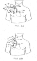
- a method of installing a catheter 10 in a patient is illustrated in Figures 6A-6D .
- an incision 100 is made in the skin of a patient.
- the proximal tips 14p, 16p of catheter 10 are inserted through the incision 100 and are placed at desired locations within the patient using conventional techniques, such as the Seldinger technique.
- a trocar 120 or other suitable instrument is used to form a subcutaneous tunnel 102 having a first end 104, which is preferably coincident with the incision 100, and an opposed second end 106, which is remote from the first end 104, as shown in Figure 6A .
- the distal end 36 of the catheter 10 is inserted through the first end 104 of the tunnel 102, and the distal end 36 is guided through the tunnel 102 such that the distal end 36 extends out from the tunnel 102 at its second end 106.
- the distal extension tubes 18, 20 are sufficiently flexible that they may be bundled or clamped together by any suitable means to facilitate passing the Y-shaped distal end 36 of the catheter 10 through the tunnel 102.
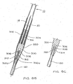
- the distal ends 18d, 20d of the distal extension tubes 18, 20 are attached to a connector 300.
- the proximal end of the connector 300 may include a first tip 302 and a second tip 304 as shown.
- the tips 302, 304 are insertable into the lumens at the distal ends 18d, 20d of the distal extension tubes 18, 20.
- the tips 302, 304 preferably include ribs 301 or the like to tightly engage within the distal ends 18d, 20d of the distal extension tubes 18,20 such that the connector 300 is securely but removably attached to the extension tubes 18, 20.
- the connector 300 holds the distal extension tubes 18, 20 in close arrangement as shown so that the distal extension tubes 18, 20 can be simultaneously subcutaneously tunneled in a patient as described below.
- the distal end of the connector 300d preferably includes a bore 306 which is configured to attachably receive an insertion tip 308 of the trocar 120.
- the bore 306 may include threads 310 which can be engaged with mating threads 312 on the insertion tip 308 of the trocar 120.
- the bore 306 may include a collar portion 314 which snaps into a groove 309 on the insertion tip 308 of the trocar 120 as shown in Figure 8C .
- the distal end 300d of the connector 300 can be engaged on the insertion tip 308 of the trocar 120 to route the attached distal extension tubes 18, 20 through the subcutaneous tunnel 102 with the trocar 120. Once the distal end 36 of the catheter 10 has been drawn through the tunnel 102, the connector 300 can be disengaged from the distal extension tubes 18, 20.
- a sheath 320 may be used as shown in Figure 8B .
- the sheath 320 is placed over at least a portion of the connector 300 and the distal extension tubes 18,20.
- the distal end 320d of the sheath 320 is tapered as shown.
- the sheath 320 and the distal portions of the catheter 10 can be drawn together through the tunnel 102 with the trocar 120.
- the sheath 320 is removed from the catheter 10 once the distal portions of the catheter 10 have been drawn through the tunnel 102.
- the distal end 36 of the catheter 10 is drawn from the second end 104 of the tunnel 102 such that the distal extension tubes 18,20 and at least a portion of the central tube portion 12 extends from the second end 104 and the catheter 10 is fully tunnelled in the patient.
- the incision 100 and the second end 104 of the tunnel are suitably treated and dressed.
- An outer portion of the central tube portion 12 may include a tissue in-growth stabilizing cuff 15, as shown in Figure 1 , for stabilizing the inserted catheter 10 in the patient.
- a portion 130 of tunnel 102 may be dilated to enlarge the width of the tunnel 102 to receive the cuff 15 as the catheter 10 is drawn through the tunnel 102.
- the dilated portion 130 of the tunnel is preferably dilated by sliding a sheath dilator 200 over an end 42 and shaft 41 of the trocar 120 when the trocar 120 is positioned in the subcutaneous tunnel 102 as shown in Figure 6A .
- the sheath dilator 200 preferably includes a hollow bore 208, a tapered leading end 206, a substantially cylindrical portion 204, and a handle 202.
- the sheath dilator 200 is inserted through the first end 104 of the tunnel 102 and into the tunnel 102 until the tip 206 has been inserted proximate to a cuff seating point 140 in the tunnel 102 to form a dilated portion 130 of the tunnel 102.
- the sheath dilator 200 is removed from the tunnel 102 and the trocar 120.
- the catheter 10 is finally positioned in the tunnel 102 when the cuff 15 is seated near an end 140 of the dilated portion 130 of the tunnel 102 as shown in Figure 6C .
- the catheter 10 is connected to a fluid exchange device 200.
- the distal end 18d of the distal venal extension tube 18 is selectively attached to a venal leg 224 of the fluid exchange device 200 by connector hub 74.
- the distal end 20d of the distal arterial extension tube 20 is selectively attached to an arterial leg 222 of the fluid exchange device 200 by connector hub 72.
- indicia 26 and 28 may be included on the distal extension tubes 18,20 and/or the connector hubs 72, 74 to assist medical personnel in identifying the proper distal extension tube 18 or 20 for connection to a corresponding leg of the fluid exchange device 300.
- the indicia 26, 28 may be markings, colors, or any other distinctive indicator.
Landscapes
- Health & Medical Sciences (AREA)
- Life Sciences & Earth Sciences (AREA)
- Heart & Thoracic Surgery (AREA)
- Hematology (AREA)
- Veterinary Medicine (AREA)
- Anesthesiology (AREA)
- Biomedical Technology (AREA)
- Engineering & Computer Science (AREA)
- Animal Behavior & Ethology (AREA)
- General Health & Medical Sciences (AREA)
- Public Health (AREA)
- Vascular Medicine (AREA)
- Pulmonology (AREA)
- Biophysics (AREA)
- Urology & Nephrology (AREA)
- Cardiology (AREA)
- Media Introduction/Drainage Providing Device (AREA)
Description
- The present invention relates generally to medical instrumentation and more specifically to a multi-lumen catheter including y-shaped distal and proximal ends, and including selectively attachable hubs for selectively connecting the catheter to a fluid exchange device.
- Catheters, generally, are hollow, flexible tubes for insertion into a body cavity, duct, or vessel to allow the passage of fluids or distend a passageway. Catheters are often used for temporary or long-term dialysis treatment. Dialysis treatment provides for blood to be withdrawn from the patient, purified, and then returned to the patient. Thus, in dialysis treatment, catheters are used to allow passage of a patient's blood into and out of the patient's body. For optimal performance during dialysis treatment, the catheter tips, both in-flow and outflow, should be placed in close proximity to the heart. Typically, medical personnel use either a double lumen catheter or two single lumen catheters. Both types, however, present certain deficiencies.
- While double lumen catheters (e.g.,
U.S. Pat. No. 4,895,561 ) allow for a single insertion of the catheter into the desired vein, double lumen catheters typically do not permit optimal catheter tip placement. Due to differences among patients, optimal tip position varies from patient to patient. Non-optimal tip position may significantly lower flow values, resulting in less effective dialysis treatment. For current double lumen catheters, a physician must make an estimate regarding the appropriate catheter tube length prior to beginning the procedure of catheterization. Then, a subcutaneous tunnel is made from a first end, which is near the area to be catheterized, to a second end, which is the preferred end position of the hub assembly, namely, away from the neck of the patient, in order to allow for more convenient access to the dialysis treatment equipment. The catheter tube is then routed forwardly into the through the subcutaneous tunnel from the second end to the first end so that the catheter tips extend outwardly from the first end of the tunnel. Either before or after tunneling, a sheath is inserted trough the first end of the tunnel and into the area to be catheterized, and the catheter tips are inserted into the sheath and the area to be catheterized. The estimated catheter tube length and subsequent forward tunneling may result in less than optimal tip placement. - With the use of two independent single lumen catheters (e.g.,
U.S. Pat. No. 5,776,111 to Tesio ) the problem of tip placement is addressed. The hub assembly of each catheter is removable from the tube and tip portion of the catheter, thereby allowing the catheter tip to be placed directly into the vein and advanced into the desired position. Then, the proximal end of the catheter can be reversed tunneled and trimmed to a desired length. Thereafter, the hub assembly is attached. Deficiencies, however, exist in this method of catheterization as well. One problem associated with this method is that this method requires two separate venous insertions, namely, two tunnels and two of each accessory instrument used for the procedure. Therefore, there is increased surgical time required to place two catheters, there are two wound entry sites which doubles the risk of post-surgical infection, and the two catheters together are significantly larger in diameter than one double lumen catheter. -
US 5947 953 (closest prior art) describes a splittable multiple catheter assembly and methods of inserting the same. The assembly includes a splittable membrane joining a first catheter and a second catheter in order to be at least partially longitudinally split from each other. - In the disclosed apparatus and method, a multi-lumen catheter includes a selectively attachable hub assembly that allows the catheter tip to be positioned accurately within a patient's vein prior to subcutaneous tunneling. The distal end of the catheter tube is selectively attachable to the hub assembly. Accordingly, after the tips of the catheter have been accurately positioned in a patient, the other end of the catheter may be reverse tunneled under the skin of a patient. Before or after tip placement, an incision is made in the skin adjacent to the point where the protruding distal end of the catheter exits the skin. A subcutaneous tunnel is then formed having a first end at the incision and a second end exiting the skin at a point remote from the first end of the tunnel, generally as the caudal direction. A sheath dilator is inserted into the tunnel, which is partially dilated so as to accommodate a tissue in-growth stabilizing cuff. The distal end of the catheter tube is routed through the subcutaneous tunnel and the cuff seated therein, thereby stabilizing the distal portion of the catheter tube in the patient. A selectively attachable hub assembly is connected to the lumens at the distal tip of the catheter tube for subsequent connection of the catheter to a fluid exchange device, such as a dialysis machine.
- While the selectively attachable hub assembly described above facilitates tunneling a multi-lumen catheter in a patient, the separable hub assembly creates the need to connect the hub to a distal end of a multi-lumen catheter tube, thereby adding an additional step to the catheter insertion/connection procedure, which increases surgical time and expense. Furthermore, the hub-catheter connection provides an additional connection which may leak or separate from the catheter tube due to external loads on the hub such as by pulling or snagging. In addition, the attachable hub assembly is a relatively complex part, which makes it difficult to manufacture and, therefore, use of the hub assembly increases the cost of the catheter itself.
- Therefore, there is a need for a multi-lumen catheter that can be inserted into a patient using a reverse tunneling technique, which permits accurate placement of the tips of the catheter into the area to be catheterized and that is selectively attachable to a fluid exchange device. The improved catheter should not required an extensive hub assembly, thus making it relatively inexpensive to manufacture and easy to insert into a patient.
- A multi-lumen catheter is provided for use in hemodialysis and the like. The multi-lumen catheter includes an elongated, central, multi-lumen tube portion having a distal end and a proximal end. The central tube portion has a substantially cylindrical outer shape and is internally segmented into a plurality of lumens. A distal branch portion includes a plurality of single-lumen distal extension tubes. Each distal extension tube has a proximal first end and a distal second end. The proximal first end of each distal extension tube is connected to the distal end of the central tube portion such that the single lumen of each distal extension tube is in fluid communication with one of the plurality of lumens of the central tube portion. A proximal branch portion includes a plurality of single-lumen proximal extension tubes. Each proximal extension tube has a distal first end and a proximal second end. The distal first end of each proximal extension tube is connected to the proximal end of the central tube portion such that the single lumen of each distal extension tube is in fluid communication with one of the plurality of lumens of the central tube portion. A plurality of selectively attachable connector hubs are provided, each connector hub being configured to be selectively attachable to the distal second end of one of the distal extension and being configured for selective connection to a fluid exchange device. Each lumen of the central tube portion and the lumens of the distal and proximal extension tubes in fluid communication therewith define a flow path through the catheter. An in-growth stabilizing cuff may be affixed to an outer portion of the central tube portion. ,
- The multi-lumen catheter may include a central tube portion having two lumens. In such a catheter, the distal branch portion includes two distal extension tubes, and the proximal branch portion includes two proximal extension tubes. The catheter may be arranged such that the plurality of single-lumen distal extension tubes of the distal branch portion converge to form a distal multi-lumen connecting portion which connects to the distal end of the central tube portion, and the plurality of single-lumen proximal extension tubes comprising the proximal branch portion converge to form a proximal multi-lumen connecting portion which connects to the proximal end of the central tube portion.
- The central tube portion, the distal extension tubes, and the proximal extension tubes may be comprised of a fusible material, and the distal extension tubes and proximal extension tubes may be respectively fused to the distal and proximal ends of the central tube portion. The distal extension tubes may have a substantially cylindrical outer shape near their distal second ends, and the proximal multi-lumen connecting portion may also have substantially cylindrical outer shape. The proximal extension tubes may have a substantially D-shaped cross-section over at least a portion of their length. Also, the proximal extension tubes may be substantially parallel to each other in a free state, and the proximal second ends of the distal extension tubes may be longitudinally spaced from each other.
- The multi-lumen catheter may further include a plurality of connector hubs for connecting the catheter to a fluid exchange device. Each connector hub may configured to be connected to the distal second end of one of the distal extension tubes, and configured for connection to a portion of a fluid exchange apparatus. Each of the proximal extension tubes may include a tube wall, and each of the proximal extension tubes may include at least one opening extending through its tube wall. Further, an external portion of at least one of the distal extension tubes may include indicia which indicates a discrete flow path through the catheter.. In one arrangement, the two proximal extension tubes have longitudinal axes which intersect at an included angle in a free state, the included angle being in a range from about 10 degrees to about 30 degrees.
- A y-shaped catheter junction for a multi-lumen catheter is also provided. The y-shaped junction includes a dual-lumen trunk, having a substantially cylindrical outer wall, a first end, a second end, a first lumen, and a second lumen. A first single-lumen extension tube is connected to the first end of the trunk, such that the single lumens of the first single-lumen extension tube is in fluid communication with the first lumen of the trunk. A second single-lumen extension tube is connected to the first end of the trunk such that the single lumen of the second single-lumen extension tube is in fluid communication with the second lumen of the trunk. The y-shaped junction is arranged such that the first lumen of the trunk and the first extension tube define a first flow path, and the second lumen of the trunk and the second extension tube define a second flow path. The y-shaped catheter junction may also be arranged such that the first and second extension tubes have longitudinal axes which intersect at an included angle near the first end of the trunk in a free state, the included angle being in a range from about 10 degrees to about 30 degrees.
- A method of forming a multi-lumen catheter is also disclosed. The method includes attaching a first plurality of single-lumen extension tubes to a distal end of a length of multi-lumen tubing comprising a plurality of multiple lumens, and attaching a second plurality of single-lumen extension tubes to a distal end of the length of multi-lumen tubing. Each single lumen of each extension tube is in fluid communication with one of the lumens of the length of multi-lumen tubing. The length of multi-lumen tubing may include two lumens, and the first and second pluralities of extension tubes may form substantially y-shaped junctions on each end of the length of multi-lumen tubing.
- The method of forming a multi-lumen catheter may include first forming a y-shaped distal junction. The process may include providing a first length of single-lumen tubing to form a distal arterial extension tube, providing a second length of single-lumen tubing to form a distal venal extension tube, providing a first length of multi-lumen tubing comprising at least an arterial lumen and a venal lumen, and having a distal end and a proximal end, attaching an end of the distal arterial extension tube to the distal end of the first length of multi-lumen tubing such that the distal arterial extension tube is in fluid communication with the arterial lumen of the first length of multi-lumen tubing, and attaching an end of the distal venal extension tube to the distal end of the first length of multi-lumen tubing such that the distal venal extension tube is in fluid communication with the venal lumen of the first length of multi-lumen tubing. The proximal end of the first length of multi-lumen tubing forms a connecting end.
- A second length of multi-lumen tubing having a distal end and a proximal end is provided. The tubing includes an arterial lumen and a venal lumen. The connecting end of the first length of multi-lumen tubing is connected to the distal end of the second length of multilumen tubing, such that the arterial extension tube of the distal junction is in fluid communication with the arterial lumen of the second length of multi-lumen tubing, and the venal extension tube of the distal junction is in fluid communication with the venal lumen of the second length of multi-lumen tubing.
- A y-shaped proximal junction is also formed. This process includes providing a third length of single-lumen tubing to form a proximal arterial extension tube, and providing a fourth length of single-lumen tubing to form a proximal venal extension tube. A third length of multilumen tubing is also provided which includes at least an arterial lumen and a venal lumen, and has a distal end and a proximal end. An end of the proximal arterial extension tube is attached to the distal end of the third length of multi-lumen tubing such that the proximal arterial extension tube is in fluid communication with the arterial lumen of the third length of multi-lumen tubing. Also, an end of the proximal venal extension tube is attached to the distal end of the third length of multi-lumen tubing such that the proximal venal extension tube is in fluid communication with the venal lumen of the third length of multi-lumen tubing. The distal end of the third length of multi-lumen tubing forms an attachment end.
- The attachment end of the third length of multi-lumen tubing is attached to the proximal end of the second length of multi-lumen tubing, such that the arterial extension tube of the proximal junction is in fluid communication with the arterial lumen of the second length of multi-lumen tubing, and the venal extension tube of the proximal junction is in fluid communication with the venal lumen of the second length of multi-lumen tubing. The method may also include forming at least one opening in a wall of the proximal venal extension tube, and forming at least one opening in a wall of the arterial proximal extension tube. The steps of attaching extension tubes and lengths of multi-lumen tubing together or to each other may include heat welding or similar fusing techniques. The longitudinal axes of the distal arterial extension tube and distal venal extension tube may be arranged to intersect at an included angle in a free state in a range from about 10 degrees to about 30 degrees.
- A method for surgically implanting a double-y shaped multi-lumen catheter into a patient is also provided. The method is suited for implanting a multi-lumen catheter having a an elongated, central, multi-lumen tube portion, a proximal end portion including a single-lumen proximal venal extension tube and a single-lumen proximal arterial extension tube each having a proximal tip, and a distal end portion including a single-lumen distal venal extension tube and a single-lumen distal arterial extension tube each having a distal end. The method includes making an incision in the skin of the patient, and inserting the proximal tips of the proximal venal and arterial extension tubes through the incision and placing the proximal tips in the patient. A subcutaneous tunnel is formed having a first end proximate to the incision and a second end remote from the first end of the tunnel. The distal venal and arterial extension tubes and at least a portion of the central tube portion are guided through the subcutaneous tunnel such that at least the distal ends of the distal venal and arterial extension tubes extend outwardly from the tunnel through the second end of the tunnel. At least a portion of the distal end portion of the catheter is secured to the patient such as by sutures or any other suitable means.
- When the catheter includes a stabilizing cuff, the method may further include dilating at least a portion of the subcutaneous tunnel to receive the cuff. Dilation of the tunnel may be accomplished by sliding a sheath dilator along the shaft of a trocar longitudinally positioned within the tunnel. The distal end portion of the catheter is secured to the patient by seating the cuff in a dilated portion of the subcutaneous tunnel.
- The catheter implanting method may further include respectively connecting the distal arterial and venal extension tubes to arterial and venal legs of a fluid exchange device. Connecting the distal arterial and venal extension tubes may include connecting the distal arterial extension tube to the arterial leg with a first connector hub, and connecting the proximal venal extension tubes to the venal leg with a second connector hub. Inserting the proximal tips of the proximal venal and arterial extension tubes into a patient may include placing the proximal tip of the venal extension tube into a vein in the patient, and placing the proximal tip of the arterial extension tube into an artery in the patient.
- These and other aspects of the invention will be made clear from a reading the following detailed description together with the drawings.
-
-
Figure 1 is a perspective view of a double y-shaped multi-lumen catheter; -
Figure 2 is a cross-sectional view of a distal portion of the multi-lumen catheter ofFigure 1 ; -
Figure 3 is a partially exploded detail perspective view of a distal portion of the multilumen catheter ofFigure 1 ; -
Figure 4 is a partially exploded detail perspective view of a proximal portion of the multilumen catheter ofFigure 1 ; -
Figure 5 is a cross-sectional view of a proximal portion of the multi-lumen catheter ofFigure 1 ; -
Figures 6A-6D illustrate a procedure for tunneling a multi-lumen catheter like that ofFigure 1 in a patient; -
Figure 7 is a partial sectional view of a sheath dilator engaged along a trocar to dilate a portion of a subcutaneous tunnel in a patient; -
Figures 8A-8C are views of a connection between a distal end of the catheter and a trocar for guiding the catheter through a subcutaneous tunnel. - For the purposes of the following description and the claims appended hereto, the relative term "proximal" refers to those portions of a catheter and those portions of components of the catheter which are nearest the insertion end of the catheter, that is, the end of the catheter that is inserted into an area of a patient's body being catheterized, such as a blood vessel. Conversely, the relative term "distal" refers to those portions of a catheter and those portions of components of the catheter which are farthest from the insertion end of the catheter.
-
Figure 1 shows a double-Y shapedmulti-lumen catheter 10 according to the present invention. Thecatheter 10 includes aproximal end 34 for insertion into a patient, and adistal end 36 for connection to a fluid exchange device, such as a dialysis machine or the like. Thecatheter 10 includes an elongated, central,multi-lumen tube portion 12, a plurality of proximal single-lumen extension tubes lumen extension tubes central tube portion 12 includes anarterial lumen 5 and a venal lumen 6. In this arrangement, thecatheter 10 includes a proximalvenal extension tube 14 and a distalvenal extension tube 18 in fluid communication with the venal lumen 6, and a proximalarterial extension tube 16 and a distal arterial extension tube in fluid communication with thearterial lumen 5. Thecatheter 10 may include a stabilizingcuff 15 affixed to an outer portion of thecentral tube portion 12 as shown inFigure 1 . Preferably, thecuff 15 is longitudinally positioned on thecentral tube portion 12 such that thecuff 15 will be finally positioned in a subcutaneous tunnel in a patient as described more fully below. - A construction for the
distal end 36 of themulti-lumen catheter 10 is shown inFigures 1-3 . As shown inFigures 2 and3 , the proximal ends 18p, 20p of thedistal extension tubes distal end 12d of thecentral tube portion 12 by a distalmulti-lumen trunk 30. The multiple lumens of thedistal trunk 30 correspond in number to the multiple lumens of thecentral tube portion 12 and the number ofdistal extension tubes distal trunk 30 includes a venaldistal trunk lumen 48, and an arterialdistal trunk lumen 47 as shown inFigure 2 . As shown inFigure 3 , the proximal ends 18p, 20p of thedistal extension tubes distal end 30d of the distal trunk, thereby forming a substantially Y-shaped junction. Theproximal end 30p of thedistal trunk 30 is connected to thedistal end 12d of thecentral tube portion 12 as shown inFigure 2 , thereby forming a Y-shapeddistal end 36. Theproximal end 30p of thedistal trunk 30 is substantially cylindrical in shape, and is substantially equal in outer diameter to the outer diameter of thecentral tube portion 12, thereby providing a smooth transition at the juncture between thedistal trunk 30 and thecentral tube portion 12. - As shown in
Figure 2 , the distal extension tubes are arranged such that an included angle "θ" exists between the longitudinal axes of thetubes distal extension tubes distal trunk lumen 48 is in fluid communication with the venal lumen 6 of thecentral tube portion 12 and the single lumen of the distalvenal extension tube 18. Similarly, the arterialdistal trunk lumen 47 is in fluid communication with thearterial lumen 5 of the and the single lumen of the distalarterial extension tube 20. - In an alternative arrangement, the
distal extension tubes distal end 12d of thecentral tube portion 12 rather than to an interconnected distal trunk 30 (not shown). In either arrangement, the mating end portions of thedistal extension tubes central tube portion 12d, and/or thedistal trunk 30 are sealably fused together by heat welding or the like such that the fluid communication between the interconnecting lumens of the components is established and maintained and no leakage occurs at the connections. - As shown in
Figures 1-3 , thecatheter 10 also includes selectivelyattachable connector hubs distal extension tubes connector hubs connector hubs distal end 36 of thecatheter 10 after insertion of theproximal end 34 of thecatheter 10 into a patient, and after reverse, subcutaneous tunneling of thedistal end 36. As shown inFigures 1 and2 , theconnector hubs distal ends distal extension tubes venal connector hub 74 is selectively attachable to thedistal portion 18d of the distalvenal extension tube 18, and thearterial connector hub 72 is selectively attachable to thedistal portion 20d of the distalarterial extension tube 20. - In one embodient as shown in
Figures 1-3 , the selectivelyattachable hubs mating compression fittings cannulae male portions distal extension tubes connector hubs Figure 2 . When fully engaged, thehubs compression fittings compress compression sleeves 70 about thedistal portions distal extension tubes compression fittings type fittings connector tubes type fittings fluid exchange device 200. For example, the distal ends of the luer-type fittings fluid exchange device 200. Other types of known leak-tight selectively attachable connection configurations may also be used. - As shown in
Figures 1 and3 , theconnector hubs distal extension tubes distal end 36 of thecatheter 10 to be subcutaneously reverse tunneled in a patient as described more fully below without interference from thehubs catheter 10 is subcutaneously reverse tunneled in a patient such that thedistal end 36 protrudes outwardly from the patient, thehubs distal extension tubes hub 72 inFigure 3 . Thecompression sleeves 70 can then be placed over thedistal ends extension tubes Figure 2 . Thecatheter 10 can then be connected to afluid exchange device 200. - A construction for the
proximal end 34 of thecatheter 10 is shown inFigures 1 ,4 , and5 . The distal ends 14d, 16d of theproximal extension tubes proximal end 12p of thecentral tube portion 12 by a proximalmulti-lumen trunk 32. The lumens of theproximal trunk 32 correspond in number to the multiple lumens of thecentral tube portion 12 and to the number ofproximal extension tubes proximal trunk 32 includes a venalproximal trunk lumen 31, and an arterial proximal trunk lumen 33 as shown inFigure 5 . As shown inFigure 4 , the distal ends 14d, 16d of theproximal extension tubes proximal end 32p of theproximal trunk 32, thereby forming a substantially Y-shaped junction. Thedistal end 32d of theproximal trunk 32 is connected to theproximal end 12p of thecentral tube portion 12 as shown inFigure 5 , thereby forming a substantially Y-shapedproximal end 34 on thecatheter 10. Preferably, thedistal end 32d of theproximal trunk 32 is substantially cylindrical in shape, and is substantially equal in outer diameter to the outer diameter of thecentral tube portion 12, thereby providing a smooth transition at the juncture between theproximal trunk 32 and thecentral tube portion 12. - As shown in
Figure 4 , the proximal extension tubes are arranged such that an included angle "α" exists between the longitudinal axes of thetubes distal extension tubes proximal trunk lumen 31 is in fluid communication with the venal lumen 6 of thecentral tube portion 12 and the single lumen of the proximalvenal extension tube 14. Similarly, the arterial proximal trunk lumen 33 is in fluid communication with thearterial lumen 5 of thecentral tube portion 12 and the single lumen of the proximalarterial extension tube 16. - In an alternative arrangement, the
proximal extension tubes proximal end 12p of thecentral tube portion 12 rather than to an interconnecting proximal trunk 32 (not shown). In either arrangement, the mating end portions of theproximal extension tubes central tube portion 12p, and/or theproximal trunk 32 are sealably fused together, such as by heat welding or the like, such that the fluid communication between the interconnected lumens of the components is established and maintained and no leakage occurs at the connections. - As shown in
Figures 1 ,4 , and5 , the proximalarterial extension tube 16 is preferably shorter in length than the proximalvenal extension tube 14. For example, the proximalarterial extension tube 16 may be about 4 cm shorter in length than the proximalvenal extension tube 14. The resulting longitudinal spacing between theproximal tips Figure 4 , the proximalvenal extension tube 14 may include anend opening 43 in or near itsproximal tip 14p. The proximalvenal extension tube 14 may also include one or moretransverse openings 42 in itstube wall 40. Similarly, as also shown inFigure 4 , the proximalarterial extension tube 16 may include anend opening 47 in or near itsproximal tip 16p. The proximalarterial extension tube 16 may also include one or moretransverse openings 46 in itstube wall 44. Theopenings proximal extension tubes - The
hubs distal end 36 of thecatheter 10 to facilitate tunneling thecatheter 10 in a patient. A method of installing acatheter 10 in a patient is illustrated inFigures 6A-6D . As shown inFigure 6A , anincision 100 is made in the skin of a patient. Theproximal tips catheter 10 are inserted through theincision 100 and are placed at desired locations within the patient using conventional techniques, such as the Seldinger technique. - At this stage, the
distal end 36 and distal portions of thecatheter 10 extend outwardly from theincision 100. Atrocar 120 or other suitable instrument is used to form asubcutaneous tunnel 102 having afirst end 104, which is preferably coincident with theincision 100, and an opposedsecond end 106, which is remote from thefirst end 104, as shown inFigure 6A . - As shown in
Figure 6B , thedistal end 36 of thecatheter 10 is inserted through thefirst end 104 of thetunnel 102, and thedistal end 36 is guided through thetunnel 102 such that thedistal end 36 extends out from thetunnel 102 at itssecond end 106. Thedistal extension tubes distal end 36 of thecatheter 10 through thetunnel 102. - In a preferred arrangement as shown in
Figures 8A and8B , the distal ends 18d, 20d of thedistal extension tubes connector 300. The proximal end of theconnector 300 may include afirst tip 302 and asecond tip 304 as shown. Thetips distal ends distal extension tubes tips ribs 301 or the like to tightly engage within the distal ends 18d, 20d of thedistal extension tubes connector 300 is securely but removably attached to theextension tubes tips distal extension tubes connector 300 holds thedistal extension tubes distal extension tubes connector 300d preferably includes abore 306 which is configured to attachably receive aninsertion tip 308 of thetrocar 120. Thebore 306 may includethreads 310 which can be engaged withmating threads 312 on theinsertion tip 308 of thetrocar 120. Alternatively, thebore 306 may include a collar portion 314 which snaps into agroove 309 on theinsertion tip 308 of thetrocar 120 as shown inFigure 8C . In this way, thedistal end 300d of theconnector 300 can be engaged on theinsertion tip 308 of thetrocar 120 to route the attacheddistal extension tubes subcutaneous tunnel 102 with thetrocar 120. Once thedistal end 36 of thecatheter 10 has been drawn through thetunnel 102, theconnector 300 can be disengaged from thedistal extension tubes - In order to provide the distal portions of the
catheter 10 with a smooth and compact outer profile to facilitate passage of thedistal end 36 of thecatheter 10 through thetunnel 102, asheath 320 may be used as shown inFigure 8B . Thesheath 320 is placed over at least a portion of theconnector 300 and thedistal extension tubes distal end 320d of thesheath 320 is tapered as shown. Thesheath 320 and the distal portions of thecatheter 10 can be drawn together through thetunnel 102 with thetrocar 120. Thesheath 320 is removed from thecatheter 10 once the distal portions of thecatheter 10 have been drawn through thetunnel 102. - As shown in
Figure 6C , thedistal end 36 of thecatheter 10 is drawn from thesecond end 104 of thetunnel 102 such that thedistal extension tubes central tube portion 12 extends from thesecond end 104 and thecatheter 10 is fully tunnelled in the patient. Theincision 100 and thesecond end 104 of the tunnel are suitably treated and dressed. - An outer portion of the
central tube portion 12 may include a tissue in-growth stabilizing cuff 15, as shown inFigure 1 , for stabilizing the insertedcatheter 10 in the patient. Referring toFigures 6C and7 , when thecatheter 10 includes a stabilizingcuff 15, aportion 130 oftunnel 102 may be dilated to enlarge the width of thetunnel 102 to receive thecuff 15 as thecatheter 10 is drawn through thetunnel 102. As shown inFigure 7 , the dilatedportion 130 of the tunnel is preferably dilated by sliding asheath dilator 200 over anend 42 andshaft 41 of thetrocar 120 when thetrocar 120 is positioned in thesubcutaneous tunnel 102 as shown inFigure 6A . Thesheath dilator 200 preferably includes ahollow bore 208, a taperedleading end 206, a substantiallycylindrical portion 204, and ahandle 202. Thesheath dilator 200 is inserted through thefirst end 104 of thetunnel 102 and into thetunnel 102 until thetip 206 has been inserted proximate to acuff seating point 140 in thetunnel 102 to form a dilatedportion 130 of thetunnel 102. Once the dilatedportion 130 is sufficiently dilated, thesheath dilator 200 is removed from thetunnel 102 and thetrocar 120. Thecatheter 10 is finally positioned in thetunnel 102 when thecuff 15 is seated near anend 140 of the dilatedportion 130 of thetunnel 102 as shown inFigure 6C . - As shown in
Figure 6D , thecatheter 10 is connected to afluid exchange device 200. Thedistal end 18d of the distalvenal extension tube 18 is selectively attached to a venal leg 224 of thefluid exchange device 200 byconnector hub 74. Similarly, thedistal end 20d of the distalarterial extension tube 20 is selectively attached to anarterial leg 222 of thefluid exchange device 200 byconnector hub 72. As shown inFigure 3 ,indicia distal extension tubes connector hubs distal extension tube fluid exchange device 300. Theindicia - While this invention has been illustrated and described in accordance with a preferred embodiment, it is recognized that variations and changes may be made therein without departing from the invention as set forth in the claims. Certain modifications and improvements will occur to those skilled in the art upon a reading of the forgoing description. For example, while the multi-lumen catheter has been described with reference to a catheter with two lumens, the invention also includes multi-lumen catheters including three or more lumens as required. It should be understood that all such modifications are not contained herein for the sake of conciseness and readability, but are properly within the scope of the following claims.
Claims (21)
- A multi-lumen catheter (10) comprising:(a) a central, elongated, multi-lumen tube portion (12) having a proximal end (12p) and a distal end (12d), the central tube portion (12) having a substantially cylindrical outer shape and being internally segmented into a plurality of lumens (5, 6);(b) a distal branch portion (36) comprising a plurality of single-lumen distal extension tubes (18, 20), each distal extension tube having a proximal first end (18p, 20p) and a distal second end (18d, 20d), the proximal first end (18p, 20p) of each distal extension tube being permanently connected to the distal end (30d) of a Y-shaped distal trunk (30), the single lumen of each distal extension tube being in fluid communication with one of the plurality of lumens of the central tube portion (12);(c) a proximal branch portion (34) comprising a plurality of single-lumen proximal extension tubes (14, 16), each proximal extension tube having a distal first end (14d, 16d) and a proximal second end (14p, 16p), the distal first end of each proximal extension tube being connected to the proximal end (12p) of the central tube portion (12) such that the single lumen of each distal extension tube is in fluid communication with one of the plurality of lumens of the central tube portion (12); and(d) a plurality of selectively attachable connector hubs (72, 74) including venal and arterial connector hubs, each connector hub being configured to be selectively attachable to the distal second end of one of the distal extension tubes and being configured for selective connection to a fluid exchange device,
wherein each lumen of the central tube portion (12) and the lumens of the distal and proximal extension tubes in fluid communication therewith define a flow path through the multi-lumen catheter (10) characterized in that
the Y-shaped distal trunk (30) having a proximal end (30p) and a distal end (30d), the proximal end (30p) of the Y-shaped distal trunk (30) being connected to the distal end (12d) of the central tube portion (12), the proximal end (30p) of the Y-shaped distal trunk (30) having a substantially cylindrical outer shape, and the outer diameter of the proximal end (30p) of the Y-shaped distal trunk (30) being substantially equal to the outer diameter of the central tube portion (12). - A multi-lumen catheter according to Claim 1, wherein the central tube portion (12) includes two lumens, the distal branch portion (36) includes two single-lumen distal extension tubes (18, 20), and the proximal branch portion (34) includes two proximal extension tubes (14, 16).
- A multi-lumen catheter according to any of Claims 1 or 2, wherein the central tube portion (12), the distal extension tubes (18, 20), and the proximal extension tubes (14, 16) are comprised of a fusible material, and the distal extension tubes (18, 20) and proximal extension tubes (14, 16) are respectively fused to the distal and proximal ends of the Y-shaped distal trunk (30).
- A multi-lumen catheter according to any of Claims 1 to 3, wherein the distal extension tubes (18, 20) have a substantially cylindrical outer shape near their distal second ends (18d, 20d).
- A multi-lumen catheter according to any of Claims 1 to 4, wherein the proximal extension tubes (14, 16) have a substantially D-shaped cross-section over at least a portion of their length.
- A multi-lumen catheter according to any of Claims 1 to 5, wherein the proximal end (30p) of the Y-shaped distal trunk (30) has a substantially cylindrical outer shape.
- A multi-lumen catheter according to any of Claims 1 to 6, wherein the proximal extension tubes (14, 16) are substantially parallel to each other in a free state.
- A multi-lumen catheter according to Claim 1, wherein at least one of the proximal extension tubes (14, 16) is shorter in length than at least one other of the proximal extension tubes (14, 16).
- A multi-lumen catheter according to any of Claims 1 to 8, further including a stabilizing cuff (15) affixed to an outer portion of the central tube portion (12).
- A multi-lumen catheter according to any of Claims 1 to 9, wherein the proximal end of each selectively attachable connector hub includes a tube portion (66, 68) configured to be sealably inserted into a portion of a lumen at the distal second end of one of the distal extension tubes (18, 20).
- A multi-lumen catheter according to Claim 10, wherein the tube portion (66, 68) of each connector hub includes at least one outer circumferential step, barb, or ridge (62, 64) for releasably gripping a portion of a distal extension tube into which the tube portion is inserted.
- A multi-lumen catheter according to any of Claims 1 to 11, wherein each of the proximal extension tubes (14, 16) includes a tube wall (40, 44), and each of the proximal extension tubes (14, 16) includes at least one opening (42, 46) extending through its tube wall.
- A multi-lumen catheter according to any of Claims 1 to 12, wherein an external portion of at least one of the distal extension tubes (14, 16) includes indicia (26, 28), the indicia indicating a discrete flow path through the catheter.
- A multi-lumen catheter according to any of Claims 2 to 13, wherein the longitudinal axes of the two distal extension tubes (18, 20) intersect at an included angle (θ) in a free state, the included angle being in a range from about 10 degrees to about 30 degrees.
- A multi-lumen catheter according to any of Claims 2 to 14, wherein the two proximal extension tubes (14, 16) have longitudinal axes which intersect at an included angle (α) in a free state, the included angle being at least about 5 degrees.
- A method of forming a multi-lumen catheter, the method comprising:permanently attaching a first plurality of single-lumen extension tubes (18, 20) to a distal end (30d) of a Y-shaped distal trunk (30);permanently attaching a central, elongated, multi-lumen tube portion (12) comprising a plurality of internally segmented lumens (5, 6) to a proximal end (30p) of the Y-shaped distal trunk (30); andforming at least one opening (42) in a wall (40) of a proximal venal extension tube (14) in fluid communication with one of the internally segmented lumens of the multi-lumen tube portion (12), and forming at least one opening (46) in a wall (44) of an arterial proximal extension tube (16) in fluid communication with the other of the internally segmented lumens of the multi-lumen tube portion (12),wherein the proximal end (30p) of the Y-shaped distal trunk (30) has a substantially cylindrical outer shape, and the outer diameter of the proximal end (30p) of the Y-shaped distal trunk (30) is substantially equal to the outer diameter of the central, elongated, multi-lumen tube portion (12), andwherein each single lumen extension tube (18, 20) is in fluid communication with one of the internally segmented lumens of the multi-lumen tube portion (12).
- A method according to Claim 16, wherein each of the first plurality of single-lumen extension tubes (18, 20) has a longitudinal axes which intersects at an included angle in a free state from the longitudinal axis of the central, elongated, multi-lumen tube portion (12).
- The method according to any of Claims 16 and 17, wherein the first plurality of single-lumen extension tubes (18, 20) have longitudinal axes which intersect at an included angle (θ) in a free state, the included angle being in a range from about 10 degrees to about 30 degrees.
- Use of a multi-lumen catheter according to any of Claims 1 to 15 for the manufacture of an apparatus for dialysis treatment.
- Use of a multi-lumen catheter according to Claim 19, wherein the plurality of single-lumen extension tubes (18, 20) are connected to arterial and venal legs of a fluid exchange device.
- Use of a multi-lumen catheter according to Claim 19 or 20, wherein the plurality of single-lumen distal extension tubes (18, 20) are connected to the arterial and venal legs of a fluid exchange device with a first connector hub and a second connector hub.
Applications Claiming Priority (3)
| Application Number | Priority Date | Filing Date | Title |
|---|---|---|---|
| US231748 | 2002-08-30 | ||
| US10/231,748 US6872198B1 (en) | 2001-01-24 | 2002-08-30 | Double-y-shaped multi-lumen catheter with selectively attachable hubs |
| PCT/US2003/027078 WO2004020019A2 (en) | 2002-08-30 | 2003-08-28 | Double-y-shaped multi-lumen catheter with selectively attachable hubs |
Publications (3)
| Publication Number | Publication Date |
|---|---|
| EP1542759A2 EP1542759A2 (en) | 2005-06-22 |
| EP1542759A4 EP1542759A4 (en) | 2008-06-04 |
| EP1542759B1 true EP1542759B1 (en) | 2014-12-03 |
Family
ID=31976805
Family Applications (1)
| Application Number | Title | Priority Date | Filing Date |
|---|---|---|---|
| EP03791935.4A Expired - Lifetime EP1542759B1 (en) | 2002-08-30 | 2003-08-28 | Double-y-shaped multi-lumen catheter with selectively attachable hubs |
Country Status (7)
| Country | Link |
|---|---|
| EP (1) | EP1542759B1 (en) |
| JP (1) | JP2005537064A (en) |
| CN (1) | CN1780657A (en) |
| AU (1) | AU2003265836B2 (en) |
| CA (1) | CA2497133C (en) |
| MX (1) | MXPA05002272A (en) |
| WO (1) | WO2004020019A2 (en) |
Families Citing this family (13)
| Publication number | Priority date | Publication date | Assignee | Title |
|---|---|---|---|---|
| US20050228364A1 (en) * | 2004-04-09 | 2005-10-13 | Richard Braga | Tunneler device |
| EP1883441A4 (en) * | 2005-05-27 | 2010-08-04 | Medical Components Inc | Catheter port assembly for extracorporeal treatment |
| US8066660B2 (en) * | 2007-10-26 | 2011-11-29 | C. R. Bard, Inc. | Split-tip catheter including lateral distal openings |
| CA2871329C (en) * | 2012-04-23 | 2019-05-28 | Aegis Medical Technologies, Llc | Multi-lumen catheter |
| US9393140B2 (en) * | 2012-04-27 | 2016-07-19 | Medtronic Vascular, Inc. | Reconfigurable stent-graft delivery system and method of use |
| US9789278B2 (en) * | 2012-09-20 | 2017-10-17 | Covidien Lp | Catheter assembly with replaceable components |
| JP7235504B2 (en) * | 2015-07-20 | 2023-03-08 | プリスティーン アクセス テクノロジーズ エルティーディー | Hemodialysis catheter with corrugated tip |
| CN108289702A (en) * | 2015-10-06 | 2018-07-17 | 米奈特朗尼克斯有限公司 | Device and method for providing focal cooling to brain and spinal cord |
| CN106730317A (en) * | 2016-12-28 | 2017-05-31 | 莫龙 | Catheter connection device |
| WO2018202268A1 (en) | 2017-05-02 | 2018-11-08 | Ambu A/S | Endoscope system |
| EP3618726A1 (en) | 2017-05-02 | 2020-03-11 | Ambu A/S | An endoscope |
| CN107224624B (en) * | 2017-06-12 | 2023-12-15 | 谢华南 | Hemodialysis device, hemodialysis apparatus, and hemodialysis method |
| CN110115599B (en) * | 2019-05-16 | 2021-09-24 | 声索生物科技(上海)有限公司 | Sheath tube assembly, ultrasonic probe and assembling method thereof |
Family Cites Families (14)
| Publication number | Priority date | Publication date | Assignee | Title |
|---|---|---|---|---|
| US4405313A (en) * | 1982-01-29 | 1983-09-20 | Sisley James R | Figure-eight, dual-lumen catheter and method of using |
| US4619643A (en) * | 1983-07-25 | 1986-10-28 | Bai Chao Liang | Catheter |
| JPS642658A (en) * | 1987-06-25 | 1989-01-06 | Terumo Corp | Multi-cavity catheter and its preparation |
| CA1326620C (en) * | 1988-10-25 | 1994-02-01 | Geoffrey S. Martin | Catheter for prolonged access |
| US5053023A (en) * | 1988-10-25 | 1991-10-01 | Vas-Cath Incorporated | Catheter for prolonged access |
| US5106368A (en) * | 1990-04-20 | 1992-04-21 | Cook Incorporated | Collapsible lumen catheter for extracorporeal treatment |
| FR2738154B1 (en) * | 1995-09-05 | 1997-12-26 | Pourchez Thierry | MULTI-PIPE CATHETER, ESPECIALLY HEMODIALYSIS |
| US5624413A (en) * | 1996-02-23 | 1997-04-29 | Medical Components, Inc. | Method for inserting a multiple catheter assembly |
| US5876366A (en) * | 1996-07-22 | 1999-03-02 | Dykstra; Todd M. | Kidney dialysis method and device |
| US5947953A (en) * | 1997-08-06 | 1999-09-07 | Hemocleanse, Inc. | Splittable multiple catheter assembly and methods of inserting the same |
| US6858019B2 (en) * | 2001-01-09 | 2005-02-22 | Rex Medical, L.P. | Dialysis catheter and methods of insertion |
| US20020099326A1 (en) * | 2001-01-24 | 2002-07-25 | Wilson Jon S. | Multi-lumen catheter with attachable hub |
| US6921396B1 (en) * | 2002-08-30 | 2005-07-26 | Arrow International, Inc. | Multi-lumen catheter with integrated connector |
| JP5498009B2 (en) | 2008-10-30 | 2014-05-21 | 国立大学法人 東京大学 | Photocatalyst material, organic matter decomposition method, interior member, air cleaning device, oxidizer manufacturing device |
-
2003
- 2003-08-28 AU AU2003265836A patent/AU2003265836B2/en not_active Ceased
- 2003-08-28 EP EP03791935.4A patent/EP1542759B1/en not_active Expired - Lifetime
- 2003-08-28 CN CNA038241951A patent/CN1780657A/en active Pending
- 2003-08-28 CA CA2497133A patent/CA2497133C/en not_active Expired - Lifetime
- 2003-08-28 WO PCT/US2003/027078 patent/WO2004020019A2/en active Application Filing
- 2003-08-28 MX MXPA05002272A patent/MXPA05002272A/en unknown
- 2003-08-28 JP JP2004531904A patent/JP2005537064A/en active Pending
Also Published As
| Publication number | Publication date |
|---|---|
| AU2003265836A1 (en) | 2004-03-19 |
| AU2003265836A2 (en) | 2004-03-19 |
| MXPA05002272A (en) | 2005-09-12 |
| EP1542759A2 (en) | 2005-06-22 |
| WO2004020019A2 (en) | 2004-03-11 |
| CN1780657A (en) | 2006-05-31 |
| EP1542759A4 (en) | 2008-06-04 |
| CA2497133A1 (en) | 2004-03-11 |
| WO2004020019A3 (en) | 2004-08-26 |
| CA2497133C (en) | 2011-05-10 |
| AU2003265836B2 (en) | 2008-01-31 |
| JP2005537064A (en) | 2005-12-08 |
Similar Documents
| Publication | Publication Date | Title |
|---|---|---|
| US6872198B1 (en) | Double-y-shaped multi-lumen catheter with selectively attachable hubs | |
| AU2003260123B2 (en) | Multi-lumen catheter with integrated connector | |
| US7128734B1 (en) | Apparatus and method for reverse tunneling a multi-lumen catheter in a patient | |
| AU2002240049B2 (en) | Multi-lumen catheter with attachable hub | |
| US7300430B2 (en) | Multi-lumen catheter with attachable hub | |
| US7794422B2 (en) | Catheter port assembly for extracorporeal treatment | |
| AU2002240049A1 (en) | Multi-lumen catheter with attachable hub | |
| EP1542759B1 (en) | Double-y-shaped multi-lumen catheter with selectively attachable hubs | |
| WO2006130133A1 (en) | Catheter port assembly for extracorporeal treatment | |
| WO2005099805A1 (en) | Tunneler device |
Legal Events
| Date | Code | Title | Description |
|---|---|---|---|
| PUAI | Public reference made under article 153(3) epc to a published international application that has entered the european phase |
Free format text: ORIGINAL CODE: 0009012 |
|
| 17P | Request for examination filed |
Effective date: 20050322 |
|
| AK | Designated contracting states |
Kind code of ref document: A2 Designated state(s): AT BE BG CH CY CZ DE DK EE ES FI FR GB GR HU IE IT LI LU MC NL PT RO SE SI SK TR |
|
| AX | Request for extension of the european patent |
Extension state: AL LT LV MK |
|
| DAX | Request for extension of the european patent (deleted) | ||
| RIN1 | Information on inventor provided before grant (corrected) |
Inventor name: GARY, FLEMING, S. Inventor name: BOYD, RONALD, D. Inventor name: FLEMING, CARL, M. Inventor name: CASSIDY, KENNETH, T. Inventor name: WILSON, JON, S. |
|
| A4 | Supplementary search report drawn up and despatched |
Effective date: 20080508 |
|
| 17Q | First examination report despatched |
Effective date: 20090814 |
|
| GRAP | Despatch of communication of intention to grant a patent |
Free format text: ORIGINAL CODE: EPIDOSNIGR1 |
|
| INTG | Intention to grant announced |
Effective date: 20140310 |
|
| GRAS | Grant fee paid |
Free format text: ORIGINAL CODE: EPIDOSNIGR3 |
|
| GRAP | Despatch of communication of intention to grant a patent |
Free format text: ORIGINAL CODE: EPIDOSNIGR1 |
|
| INTG | Intention to grant announced |
Effective date: 20140725 |
|
| GRAA | (expected) grant |
Free format text: ORIGINAL CODE: 0009210 |
|
| AK | Designated contracting states |
Kind code of ref document: B1 Designated state(s): AT BE BG CH CY CZ DE DK EE ES FI FR GB GR HU IE IT LI LU MC NL PT RO SE SI SK TR |
|
| REG | Reference to a national code |
Ref country code: GB Ref legal event code: FG4D |
|
| REG | Reference to a national code |
Ref country code: AT Ref legal event code: REF Ref document number: 699003 Country of ref document: AT Kind code of ref document: T Effective date: 20141215 Ref country code: CH Ref legal event code: EP |
|
| REG | Reference to a national code |
Ref country code: IE Ref legal event code: FG4D |
|
| REG | Reference to a national code |
Ref country code: DE Ref legal event code: R096 Ref document number: 60347074 Country of ref document: DE Effective date: 20150115 |
|
| REG | Reference to a national code |
Ref country code: NL Ref legal event code: VDEP Effective date: 20141203 |
|
| REG | Reference to a national code |
Ref country code: AT Ref legal event code: MK05 Ref document number: 699003 Country of ref document: AT Kind code of ref document: T Effective date: 20141203 |
|
| PG25 | Lapsed in a contracting state [announced via postgrant information from national office to epo] |
Ref country code: ES Free format text: LAPSE BECAUSE OF FAILURE TO SUBMIT A TRANSLATION OF THE DESCRIPTION OR TO PAY THE FEE WITHIN THE PRESCRIBED TIME-LIMIT Effective date: 20141203 Ref country code: FI Free format text: LAPSE BECAUSE OF FAILURE TO SUBMIT A TRANSLATION OF THE DESCRIPTION OR TO PAY THE FEE WITHIN THE PRESCRIBED TIME-LIMIT Effective date: 20141203 Ref country code: NL Free format text: LAPSE BECAUSE OF FAILURE TO SUBMIT A TRANSLATION OF THE DESCRIPTION OR TO PAY THE FEE WITHIN THE PRESCRIBED TIME-LIMIT Effective date: 20141203 |
|
| PG25 | Lapsed in a contracting state [announced via postgrant information from national office to epo] |
Ref country code: AT Free format text: LAPSE BECAUSE OF FAILURE TO SUBMIT A TRANSLATION OF THE DESCRIPTION OR TO PAY THE FEE WITHIN THE PRESCRIBED TIME-LIMIT Effective date: 20141203 Ref country code: GR Free format text: LAPSE BECAUSE OF FAILURE TO SUBMIT A TRANSLATION OF THE DESCRIPTION OR TO PAY THE FEE WITHIN THE PRESCRIBED TIME-LIMIT Effective date: 20150304 Ref country code: SE Free format text: LAPSE BECAUSE OF FAILURE TO SUBMIT A TRANSLATION OF THE DESCRIPTION OR TO PAY THE FEE WITHIN THE PRESCRIBED TIME-LIMIT Effective date: 20141203 Ref country code: CY Free format text: LAPSE BECAUSE OF FAILURE TO SUBMIT A TRANSLATION OF THE DESCRIPTION OR TO PAY THE FEE WITHIN THE PRESCRIBED TIME-LIMIT Effective date: 20141203 |
|
| PG25 | Lapsed in a contracting state [announced via postgrant information from national office to epo] |
Ref country code: EE Free format text: LAPSE BECAUSE OF FAILURE TO SUBMIT A TRANSLATION OF THE DESCRIPTION OR TO PAY THE FEE WITHIN THE PRESCRIBED TIME-LIMIT Effective date: 20141203 Ref country code: SK Free format text: LAPSE BECAUSE OF FAILURE TO SUBMIT A TRANSLATION OF THE DESCRIPTION OR TO PAY THE FEE WITHIN THE PRESCRIBED TIME-LIMIT Effective date: 20141203 Ref country code: CZ Free format text: LAPSE BECAUSE OF FAILURE TO SUBMIT A TRANSLATION OF THE DESCRIPTION OR TO PAY THE FEE WITHIN THE PRESCRIBED TIME-LIMIT Effective date: 20141203 Ref country code: RO Free format text: LAPSE BECAUSE OF FAILURE TO SUBMIT A TRANSLATION OF THE DESCRIPTION OR TO PAY THE FEE WITHIN THE PRESCRIBED TIME-LIMIT Effective date: 20141203 Ref country code: PT Free format text: LAPSE BECAUSE OF FAILURE TO SUBMIT A TRANSLATION OF THE DESCRIPTION OR TO PAY THE FEE WITHIN THE PRESCRIBED TIME-LIMIT Effective date: 20150403 |
|
| REG | Reference to a national code |
Ref country code: DE Ref legal event code: R097 Ref document number: 60347074 Country of ref document: DE |
|
| PLBE | No opposition filed within time limit |
Free format text: ORIGINAL CODE: 0009261 |
|
| STAA | Information on the status of an ep patent application or granted ep patent |
Free format text: STATUS: NO OPPOSITION FILED WITHIN TIME LIMIT |
|
| PG25 | Lapsed in a contracting state [announced via postgrant information from national office to epo] |
Ref country code: DK Free format text: LAPSE BECAUSE OF FAILURE TO SUBMIT A TRANSLATION OF THE DESCRIPTION OR TO PAY THE FEE WITHIN THE PRESCRIBED TIME-LIMIT Effective date: 20141203 |
|
| 26N | No opposition filed |
Effective date: 20150904 |
|
| PG25 | Lapsed in a contracting state [announced via postgrant information from national office to epo] |
Ref country code: SI Free format text: LAPSE BECAUSE OF FAILURE TO SUBMIT A TRANSLATION OF THE DESCRIPTION OR TO PAY THE FEE WITHIN THE PRESCRIBED TIME-LIMIT Effective date: 20141203 |
|
| PG25 | Lapsed in a contracting state [announced via postgrant information from national office to epo] |
Ref country code: MC Free format text: LAPSE BECAUSE OF FAILURE TO SUBMIT A TRANSLATION OF THE DESCRIPTION OR TO PAY THE FEE WITHIN THE PRESCRIBED TIME-LIMIT Effective date: 20141203 Ref country code: LU Free format text: LAPSE BECAUSE OF FAILURE TO SUBMIT A TRANSLATION OF THE DESCRIPTION OR TO PAY THE FEE WITHIN THE PRESCRIBED TIME-LIMIT Effective date: 20150828 |
|
| REG | Reference to a national code |
Ref country code: CH Ref legal event code: PL |
|
| PG25 | Lapsed in a contracting state [announced via postgrant information from national office to epo] |
Ref country code: LI Free format text: LAPSE BECAUSE OF NON-PAYMENT OF DUE FEES Effective date: 20150831 Ref country code: CH Free format text: LAPSE BECAUSE OF NON-PAYMENT OF DUE FEES Effective date: 20150831 |
|
| PG25 | Lapsed in a contracting state [announced via postgrant information from national office to epo] |
Ref country code: BE Free format text: LAPSE BECAUSE OF FAILURE TO SUBMIT A TRANSLATION OF THE DESCRIPTION OR TO PAY THE FEE WITHIN THE PRESCRIBED TIME-LIMIT Effective date: 20141203 |
|
| REG | Reference to a national code |
Ref country code: IE Ref legal event code: MM4A |
|
| PG25 | Lapsed in a contracting state [announced via postgrant information from national office to epo] |
Ref country code: IE Free format text: LAPSE BECAUSE OF NON-PAYMENT OF DUE FEES Effective date: 20150828 |
|
| REG | Reference to a national code |
Ref country code: FR Ref legal event code: PLFP Year of fee payment: 14 |
|
| PG25 | Lapsed in a contracting state [announced via postgrant information from national office to epo] |
Ref country code: HU Free format text: LAPSE BECAUSE OF FAILURE TO SUBMIT A TRANSLATION OF THE DESCRIPTION OR TO PAY THE FEE WITHIN THE PRESCRIBED TIME-LIMIT; INVALID AB INITIO Effective date: 20030828 Ref country code: BG Free format text: LAPSE BECAUSE OF FAILURE TO SUBMIT A TRANSLATION OF THE DESCRIPTION OR TO PAY THE FEE WITHIN THE PRESCRIBED TIME-LIMIT Effective date: 20141203 |
|
| REG | Reference to a national code |
Ref country code: FR Ref legal event code: PLFP Year of fee payment: 15 |
|
| PG25 | Lapsed in a contracting state [announced via postgrant information from national office to epo] |
Ref country code: TR Free format text: LAPSE BECAUSE OF FAILURE TO SUBMIT A TRANSLATION OF THE DESCRIPTION OR TO PAY THE FEE WITHIN THE PRESCRIBED TIME-LIMIT Effective date: 20141203 |
|
| REG | Reference to a national code |
Ref country code: FR Ref legal event code: PLFP Year of fee payment: 16 |
|
| REG | Reference to a national code |
Ref country code: DE Ref legal event code: R081 Ref document number: 60347074 Country of ref document: DE Owner name: TELEFLEX LIFE SCIENCES LIMITED, MT Free format text: FORMER OWNER: ARROW INTERNATIONAL, INC., READING, PA., US |
|
| PGFP | Annual fee paid to national office [announced via postgrant information from national office to epo] |
Ref country code: IT Payment date: 20220819 Year of fee payment: 20 Ref country code: GB Payment date: 20220829 Year of fee payment: 20 Ref country code: DE Payment date: 20220829 Year of fee payment: 20 |
|
| PGFP | Annual fee paid to national office [announced via postgrant information from national office to epo] |
Ref country code: FR Payment date: 20220825 Year of fee payment: 20 |
|
| REG | Reference to a national code |
Ref country code: GB Ref legal event code: 732E Free format text: REGISTERED BETWEEN 20221103 AND 20221109 |
|
| REG | Reference to a national code |
Ref country code: DE Ref legal event code: R071 Ref document number: 60347074 Country of ref document: DE |
|
| REG | Reference to a national code |
Ref country code: GB Ref legal event code: PE20 Expiry date: 20230827 |
|
| PG25 | Lapsed in a contracting state [announced via postgrant information from national office to epo] |
Ref country code: GB Free format text: LAPSE BECAUSE OF EXPIRATION OF PROTECTION Effective date: 20230827 |