EP1542508A1 - A device for determining the location of cooking utensils on a cooking hob - Google Patents
A device for determining the location of cooking utensils on a cooking hob Download PDFInfo
- Publication number
- EP1542508A1 EP1542508A1 EP03028048A EP03028048A EP1542508A1 EP 1542508 A1 EP1542508 A1 EP 1542508A1 EP 03028048 A EP03028048 A EP 03028048A EP 03028048 A EP03028048 A EP 03028048A EP 1542508 A1 EP1542508 A1 EP 1542508A1
- Authority
- EP
- European Patent Office
- Prior art keywords
- conductors
- couple
- heating elements
- cooking
- connecting means
- Prior art date
- Legal status (The legal status is an assumption and is not a legal conclusion. Google has not performed a legal analysis and makes no representation as to the accuracy of the status listed.)
- Granted
Links
- 238000010411 cooking Methods 0.000 title claims abstract description 12
- 238000010438 heat treatment Methods 0.000 claims abstract description 25
- 239000004020 conductor Substances 0.000 claims abstract description 18
- 238000001514 detection method Methods 0.000 claims abstract description 13
- 239000011159 matrix material Substances 0.000 claims abstract description 10
- 239000000243 solution Substances 0.000 description 9
- 230000005672 electromagnetic field Effects 0.000 description 3
- 238000000034 method Methods 0.000 description 2
- 230000003321 amplification Effects 0.000 description 1
- 230000008878 coupling Effects 0.000 description 1
- 238000010168 coupling process Methods 0.000 description 1
- 238000005859 coupling reaction Methods 0.000 description 1
- 230000000694 effects Effects 0.000 description 1
- 230000002708 enhancing effect Effects 0.000 description 1
- 239000002241 glass-ceramic Substances 0.000 description 1
- 230000006698 induction Effects 0.000 description 1
- 238000002347 injection Methods 0.000 description 1
- 239000007924 injection Substances 0.000 description 1
- 238000009413 insulation Methods 0.000 description 1
- 239000002184 metal Substances 0.000 description 1
- 238000003199 nucleic acid amplification method Methods 0.000 description 1
Images

Classifications
-
- H—ELECTRICITY
- H05—ELECTRIC TECHNIQUES NOT OTHERWISE PROVIDED FOR
- H05B—ELECTRIC HEATING; ELECTRIC LIGHT SOURCES NOT OTHERWISE PROVIDED FOR; CIRCUIT ARRANGEMENTS FOR ELECTRIC LIGHT SOURCES, IN GENERAL
- H05B3/00—Ohmic-resistance heating
- H05B3/68—Heating arrangements specially adapted for cooking plates or analogous hot-plates
- H05B3/74—Non-metallic plates, e.g. vitroceramic, ceramic or glassceramic hobs, also including power or control circuits
- H05B3/746—Protection, e.g. overheat cutoff, hot plate indicator
-
- H—ELECTRICITY
- H05—ELECTRIC TECHNIQUES NOT OTHERWISE PROVIDED FOR
- H05B—ELECTRIC HEATING; ELECTRIC LIGHT SOURCES NOT OTHERWISE PROVIDED FOR; CIRCUIT ARRANGEMENTS FOR ELECTRIC LIGHT SOURCES, IN GENERAL
- H05B2213/00—Aspects relating both to resistive heating and to induction heating, covered by H05B3/00 and H05B6/00
- H05B2213/03—Heating plates made out of a matrix of heating elements that can define heating areas adapted to cookware randomly placed on the heating plate
-
- H—ELECTRICITY
- H05—ELECTRIC TECHNIQUES NOT OTHERWISE PROVIDED FOR
- H05B—ELECTRIC HEATING; ELECTRIC LIGHT SOURCES NOT OTHERWISE PROVIDED FOR; CIRCUIT ARRANGEMENTS FOR ELECTRIC LIGHT SOURCES, IN GENERAL
- H05B2213/00—Aspects relating both to resistive heating and to induction heating, covered by H05B3/00 and H05B6/00
- H05B2213/05—Heating plates with pan detection means
Definitions
- the present invention relates to a device for determining the location of cooking utensils on a cooking hob comprising a plurality of heating elements distributed in a matrix pattern below a heat-resistant surface on which the cooking utensil can be placed in a random manner, each heating element being capable of working also as a magnetic field transmitter, the device comprising loops placed substantially around portions of the matrix of heating elements and working as magnetic field receivers.
- a device of this type is disclosed in EP-A-1206164.
- the present invention relates to an improvement of the receiving coil antennae or loops used to pick up the electromagnetic field generated by the heating elements.
- the invention relates also to some enhancing and cost reduction techniques of the pan detection system for cooking hobs with discrete distributed heating elements as disclosed in EP-A-1303168.
- the basic form of said receiving pickup coils or loops is that of one or more coils made of conducing metal wires or the like laying between the glass-ceramic slab and the heating elements.
- This basic implementation even if it works in a satisfactory manner, nevertheless has some practical and technological problems that are addressed in this invention.
- the basic known solution presents the following problems:
- the spatial resolution of the system i.e. the ability of detecting only metallic objects lying just over the heating element and not in its surroundings, is generally poor if the pickup loops are significantly larger than the emitting coils which are also the heating elements.
- the present invention solves all the above problems, providing a solution that is economical, easy to be produced, robust and guarantees high and reliable detecting performances. It is an object of the present invention to overcome or minimize the problem associated with the conventional pickup loops, providing a cheaper, more reliable and better performing solution.
- the solution according to the invention solves all said issues by using a conductor (i.e. wire, track or the like) interposed between each couple of adjacent rows or columns of the matrix of heating elements, connecting means being provided for linking each loop to a detection circuit.
- a conductor i.e. wire, track or the like
- a pot detection system is based on the cross-inductive principle (or transformer principle), in which each receiving conductor is substantially different than a coil or loop, but it can assume the function of a coil by establishing, for instance by means of electronic multiplexers, a conductive path substantially encircling the magnetic field generated by the emitting coil of the heating element.
- More than one receiving loop is preferably used in order to detect a magnetically induced voltage, said coils being connected together at one or more points and sharing one or more linear conductors.
- an electronic multiplexing circuit that can be used to detect -in distinct times- the voltages developed by magnetic induction in two of at least three points of an electrically conducting material, these two points being substantially equivalent to the terminals of a single turn coil enclosing the magnetic field generated by the emitting coil to be sensed.
- the differential voltage developed at the free ends of each pair of legs is substantially equivalent to the differential voltage that would be developed at the ends of a coil embracing the same area delimited by the two addressed legs and the common conductor.
- connection of each loop to the detection circuit may be performed through an electronic multiplexing technique in order to realize loop equivalent conducting paths, starting from non coil-shaped conductive paths, in a manner that will be explained in the following detailed description of different embodiments, given by way of non-limiting example, and illustrated in the accompanying drawings, in which:
- a first embodiment of the invention is realized by creating a single turn pick-up loop or coil over each column of heating elements by sharing a common "leg" 10 between two adjacent columns, the shared leg being connected to the ground reference 5 of the detection circuit 3.
- Said arrangement has the advantage that the number of vertical conductors is reduced from 2n to 1.5n, being n the number of loops to be sensed.
- a third embodiment of the present invention can further reduce the number of vertical conductors needed to implement n sensing loops from 1.5n to n+1 .
- Such embodiment is shown in figure 4, in which the leg-sharing concept is extended to all the legs but the outer ones.
- the receiving loops are realized by means of electronic multiplexing of the legs on a comb-shaped conductive structure substituting the regular coils of the previous solutions.
- Said comb-like structure is made of a common edge 12, and a number of legs 2a,.., 21 substantially running parallel to the rows or the columns of heating elements to be sensed for pot presence.
- the heating element 6 for sensing pot presence, the heating element 6 is used. As described in the prior art, an alternate current is flown into the coil of the heating element 6, thus generating a magnetic field leaking from the cell as a fountain.
- the two electronic multiplexers 7a and 7b are addressed by a suitable electronic control, in order to switch into the differential amplifier 8 the two comb legs 2h and 2i adjacent to the cell 6. This is electrically equivalent to have a real loop wound around the column into which lies the cell 6.
- FIG. 5 A substantially equivalent solution is shown in figure 5, in which the comb structure is electrically floating and is brought to ground 5 by means of the electronic multiplexer 7b', while the other multiplexer 7a' connects the other leg to a ground referenced amplifier 8' connected to the detection circuitry 9.
Landscapes
- Chemical & Material Sciences (AREA)
- Engineering & Computer Science (AREA)
- Ceramic Engineering (AREA)
- Geophysics And Detection Of Objects (AREA)
- General Induction Heating (AREA)
Abstract
Description
- The present invention relates to a device for determining the location of cooking utensils on a cooking hob comprising a plurality of heating elements distributed in a matrix pattern below a heat-resistant surface on which the cooking utensil can be placed in a random manner, each heating element being capable of working also as a magnetic field transmitter, the device comprising loops placed substantially around portions of the matrix of heating elements and working as magnetic field receivers.
- A device of this type is disclosed in EP-A-1206164. In particular, the present invention relates to an improvement of the receiving coil antennae or loops used to pick up the electromagnetic field generated by the heating elements.
- The invention relates also to some enhancing and cost reduction techniques of the pan detection system for cooking hobs with discrete distributed heating elements as disclosed in EP-A-1303168.
- The basic form of said receiving pickup coils or loops, as described in EP-A-1206164, is that of one or more coils made of conducing metal wires or the like laying between the glass-ceramic slab and the heating elements. This basic implementation, even if it works in a satisfactory manner, nevertheless has some practical and technological problems that are addressed in this invention. In particular, the basic known solution presents the following problems:
- the pickup loops are very difficult to be realized with more than one turn because of the space and temperature constraints;
- in order to guarantee good spatial accuracy, the pickup loops cannot be too large compared to the size of the heating elements, this means that the number of loops practically needed are in the range of 1 each 10 cells;
- the implementation of the pickup loops as described in EP-A-1206164 rises problems of cost and mutual mechanical interference of the pickup loops.
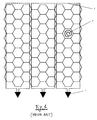
- One possible arrangement of the pickup loops, as described in EP-A-1206164 could be similar to that disclosed in attached figure 1. In this example a cooktop made of a matrix of 72 cells arranged in 8 rows and 9 columns is provided with 3 pickup loops, each one capturing the electromagnetic field emitted by the cells of the 3 columns it surrounds. Said solution has the following disadvantages:
- the connection to the electronic receiver requires two leads and two wires per receiving coil,
- neighboring loops must have some mechanical clearance between each other in order to avoid reciprocal touching and guarantee adequate insulation,
- the received signal strength is significantly different between the cells close to the coil loop (1st and 3rd column of each group of columns) and those far from it (2nd column). This requires some means of amplitude compensation.
- In addition to the said disadvantages, the applicant noticed that the spatial resolution of the system, i.e. the ability of detecting only metallic objects lying just over the heating element and not in its surroundings, is generally poor if the pickup loops are significantly larger than the emitting coils which are also the heating elements.
- The present invention solves all the above problems, providing a solution that is economical, easy to be produced, robust and guarantees high and reliable detecting performances. It is an object of the present invention to overcome or minimize the problem associated with the conventional pickup loops, providing a cheaper, more reliable and better performing solution.
- In order to overcome the problem of a poor spatial resolution, a number of research activities were carried out by the applicant. This latter has found that the use of pickup coils as large as one column of heating elements (or one row) greatly increases the spatial resolution (or focus). Unfortunately the physical realization of a number of one coil per each row or column of heating elements is hardly feasible because of the mechanical problem of installing such high number of metallic wires or conducting tracks running parallel to each other, isolated from each other and subjected to temperatures up to 1000 °C.
- The solution according to the invention solves all said issues by using a conductor (i.e. wire, track or the like) interposed between each couple of adjacent rows or columns of the matrix of heating elements, connecting means being provided for linking each loop to a detection circuit.
- A pot detection system according to the invention is based on the cross-inductive principle (or transformer principle), in which each receiving conductor is substantially different than a coil or loop, but it can assume the function of a coil by establishing, for instance by means of electronic multiplexers, a conductive path substantially encircling the magnetic field generated by the emitting coil of the heating element.
- More than one receiving loop is preferably used in order to detect a magnetically induced voltage, said coils being connected together at one or more points and sharing one or more linear conductors.
- According to another embodiment of the present invention, in which a single amplification and detection circuit is used, it is provided an electronic multiplexing circuit that can be used to detect -in distinct times- the voltages developed by magnetic induction in two of at least three points of an electrically conducting material, these two points being substantially equivalent to the terminals of a single turn coil enclosing the magnetic field generated by the emitting coil to be sensed.
- According to a further embodiment, in which the electrically conductor detecting body has the shape of a comb, having three or more legs, the differential voltage developed at the free ends of each pair of legs is substantially equivalent to the differential voltage that would be developed at the ends of a coil embracing the same area delimited by the two addressed legs and the common conductor.
- The connection of each loop to the detection circuit may be performed through an electronic multiplexing technique in order to realize loop equivalent conducting paths, starting from non coil-shaped conductive paths, in a manner that will be explained in the following detailed description of different embodiments, given by way of non-limiting example, and illustrated in the accompanying drawings, in which:
- figure 1 is a schematic view of a known detection system with discrete pickup loops;
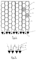
- figure 2 is a schematic view, similar to figure 1, in which a first embodiment of the present invention is shown;
- figure 3 is a detail of a second embodiment of the present invention, in which a plurality of differential receivers are used;
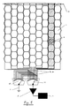
- figure 4 is a schematic view, similar to figure 1, in which a third embodiment of the present invention is shown, where a couple of multiplexers are used;
- figure 5 is a schematic view, similar to figure 4, in which a fourth embodiment of the present invention is shown.
- With reference to figure 2, a first embodiment of the invention is realized by creating a single turn pick-up loop or coil over each column of heating elements by sharing a common "leg" 10 between two adjacent columns, the shared leg being connected to the
ground reference 5 of thedetection circuit 3. Said arrangement has the advantage that the number of vertical conductors is reduced from 2n to 1.5n, being n the number of loops to be sensed. - As a man skilled in the art can easily understand, a substantially equivalent solution to that presented in figure 2 can be realized as shown in figure 3, by connecting the
common leg 10 to one input of two adjacent differential receivers 3' and the left 11 a andright leg 11 b (among which thecommon leg 10 is interposed) to the other inputs of said adjacent receivers. In order to guarantee a correct reading of pot presence, appropriate means (as described in EP-A-1206164) must be provided to avoid the simultaneous injection of electromagnetic field into two loops sharing the samecommon leg 10. - A third embodiment of the present invention can further reduce the number of vertical conductors needed to implement n sensing loops from 1.5n to n+1. Such embodiment is shown in figure 4, in which the leg-sharing concept is extended to all the legs but the outer ones. Referring to figure 4, the receiving loops are realized by means of electronic multiplexing of the legs on a comb-shaped conductive structure substituting the regular coils of the previous solutions. Said comb-like structure is made of a
common edge 12, and a number oflegs 2a,.., 21 substantially running parallel to the rows or the columns of heating elements to be sensed for pot presence. - In order to understand how this solution works, we suppose that, for sensing pot presence, the
heating element 6 is used. As described in the prior art, an alternate current is flown into the coil of theheating element 6, thus generating a magnetic field leaking from the cell as a fountain. At the same time, the twoelectronic multiplexers 7a and 7b are addressed by a suitable electronic control, in order to switch into the differential amplifier 8 the two comb legs 2h and 2i adjacent to thecell 6. This is electrically equivalent to have a real loop wound around the column into which lies thecell 6. In order to reduce the common mode disturbances and the capacitive coupling, it is convenient to tie the common side of the comb's legs to ground as shown in 5, in this way the voltage across the two addressed legs will be nearly purely differential. A substantially equivalent solution is shown in figure 5, in which the comb structure is electrically floating and is brought toground 5 by means of the electronic multiplexer 7b', while theother multiplexer 7a' connects the other leg to a ground referenced amplifier 8' connected to thedetection circuitry 9.
Claims (5)
- A device for determining the location of cooking utensils on a cooking hob comprising a plurality of heating elements distributed in a matrix pattern below a heat-resistant surface on which the cooking utensil can be placed in a random manner, each heating element being capable of working also as a transmitter or a receiver, the device comprising loops placed substantially around portions of the matrix of heating elements and working as receivers or transmitters respectively, characterized in that the loops comprise conductors (10, 11 a, 11 b, 2a, ... 21) interposed between each couple of adjacent columns or rows of the heating elements, and in that connecting means are provided for linking each loop to a detection circuit (3, 9).
- A device according to claim 1, characterized in that said connecting means comprise a plurality of ground references (5), each ground reference being interposed between two adjacent conductors connected to the detection circuit (3).
- A device according to claim 1, characterized in that said connecting means comprise a plurality of differential receivers (3'), couples of first conductors (11 a, 11 b) being connected to inputs of two adjacent differential receivers (3'), second conductors (10) interposed between each couple of first conductors (11a, 11b) being each connected to the other two inputs of said adjacent differential receivers (3').
- A device according to claim 1, characterized in that said connecting means comprise a couple of multiplexers (7a, 7b) adapted to link sequentially first ends of each couple of single consecutive conductors (2a, ...21) to the detection circuit (8, 9) in order to scan the whole matrix, the second ends (12) of such conductors being all connected together.
- A device according to claim 1, characterized in that said connecting means comprise a couple of multiplexers (7b', 7a') adapted to link sequentially first end of each couple of single consecutive conductors to ground (5) and to the detection circuit (8', 9) respectively in order to scan the whole matrix, second ends (12) of such conductors being all connected together.
Priority Applications (3)
| Application Number | Priority Date | Filing Date | Title |
|---|---|---|---|
| EP03028048A EP1542508B2 (en) | 2003-12-08 | 2003-12-08 | A device for determining the location of cooking utensils on a cooking hob |
| DE2003608704 DE60308704T2 (en) | 2003-12-08 | 2003-12-08 | Device for determining the position of cooking vessels on a cooking plate |
| ES03028048T ES2272879T5 (en) | 2003-12-08 | 2003-12-08 | A DEVICE FOR DETERMINING THE POSITION OF KITCHEN UTENSILS ON A KITCHEN PLATE. |
Applications Claiming Priority (1)
| Application Number | Priority Date | Filing Date | Title |
|---|---|---|---|
| EP03028048A EP1542508B2 (en) | 2003-12-08 | 2003-12-08 | A device for determining the location of cooking utensils on a cooking hob |
Publications (3)
| Publication Number | Publication Date |
|---|---|
| EP1542508A1 true EP1542508A1 (en) | 2005-06-15 |
| EP1542508B1 EP1542508B1 (en) | 2006-09-27 |
| EP1542508B2 EP1542508B2 (en) | 2010-10-20 |
Family
ID=34486126
Family Applications (1)
| Application Number | Title | Priority Date | Filing Date |
|---|---|---|---|
| EP03028048A Expired - Lifetime EP1542508B2 (en) | 2003-12-08 | 2003-12-08 | A device for determining the location of cooking utensils on a cooking hob |
Country Status (3)
| Country | Link |
|---|---|
| EP (1) | EP1542508B2 (en) |
| DE (1) | DE60308704T2 (en) |
| ES (1) | ES2272879T5 (en) |
Cited By (5)
| Publication number | Priority date | Publication date | Assignee | Title |
|---|---|---|---|---|
| WO2007002861A3 (en) * | 2005-06-29 | 2007-07-05 | Watlow Electric Mfg | Smart layered heater surfaces |
| WO2011012418A1 (en) * | 2009-07-29 | 2011-02-03 | BSH Bosch und Siemens Hausgeräte GmbH | Hotplate having at least two heating zones |
| CN102609017A (en) * | 2012-03-01 | 2012-07-25 | 大连理工大学 | Heating device and method capable of producing controllable temperature gradient field on metal wing structure |
| WO2017149126A1 (en) | 2016-03-04 | 2017-09-08 | Arcelik Anonim Sirketi | Induction heating cooker power control circuit |
| CN110050507A (en) * | 2016-12-19 | 2019-07-23 | Bsh家用电器有限公司 | Household appliance device |
Families Citing this family (2)
| Publication number | Priority date | Publication date | Assignee | Title |
|---|---|---|---|---|
| DE102009020628A1 (en) | 2009-05-09 | 2010-11-11 | Hettich Holding Gmbh & Co. Ohg | Hob and method for heating cooking vessels set up on the hob |
| TR201721881A2 (en) | 2017-12-26 | 2019-07-22 | Arcelik As | A METAL DETECTION SYSTEM WITH COIL FEEDING WITH A HIGH FREQUENCY GENERATOR |
Citations (4)
| Publication number | Priority date | Publication date | Assignee | Title |
|---|---|---|---|---|
| DE4007680A1 (en) * | 1990-03-10 | 1991-09-19 | Grass Ag | Glass-ceramic cooking hob - has field of sensor-driven elements each a preset different power outputs |
| WO1997019298A1 (en) * | 1995-11-21 | 1997-05-29 | Aktiebolaget Electrolux | A cooking surface with controls |
| EP1206164A2 (en) * | 2000-11-08 | 2002-05-15 | Whirlpool Corporation | Device for determining the location of cooking utensils on a cooking hob comprising discrete distributed heating elements |
| US20030071031A1 (en) * | 2001-10-17 | 2003-04-17 | Davide Gerola | Cooking hob with discrete distributed heating elements |
Family Cites Families (6)
| Publication number | Priority date | Publication date | Assignee | Title |
|---|---|---|---|---|
| FR2509562A1 (en) † | 1981-07-10 | 1983-01-14 | Cem Comp Electro Mec | METHOD AND APPARATUS FOR HOMOGENEOUS HEATING BY TRANSVERSE FLOW ELECTROMAGNETIC INDUCTION OF FLAT, CONDUCTOR AND AMAGNETIC PRODUCTS |
| DE3327622A1 (en) † | 1983-07-30 | 1985-02-07 | Blanc Gmbh & Co, 7519 Oberderdingen | Electrical hotplate for a glass-ceramic cooking plate |
| JPS618615A (en) † | 1984-06-23 | 1986-01-16 | Yoshio Shimizu | Device for detecting and tracking position of substance |
| DE19643698C2 (en) † | 1996-05-11 | 2000-04-13 | Aeg Hausgeraete Gmbh | Device for shielding conductor tracks of a hob used for capacitive measurements |
| DE10033361A1 (en) † | 2000-07-08 | 2002-01-24 | Thomas Wartmann | Matrix cooking unit has matrices of heating zones and sensor points for locating cooking vessels and measuring cooking temperatures |
| DE10048254C1 (en) † | 2000-09-29 | 2001-09-20 | Schott Glas | Pot detection system, for hotplates on ceramic hob, comprises individual conductors which run to plates from common connection and conductive layer insulated from individual conductors positioned over them in area between plates |
-
2003
- 2003-12-08 DE DE2003608704 patent/DE60308704T2/en not_active Expired - Lifetime
- 2003-12-08 EP EP03028048A patent/EP1542508B2/en not_active Expired - Lifetime
- 2003-12-08 ES ES03028048T patent/ES2272879T5/en not_active Expired - Lifetime
Patent Citations (4)
| Publication number | Priority date | Publication date | Assignee | Title |
|---|---|---|---|---|
| DE4007680A1 (en) * | 1990-03-10 | 1991-09-19 | Grass Ag | Glass-ceramic cooking hob - has field of sensor-driven elements each a preset different power outputs |
| WO1997019298A1 (en) * | 1995-11-21 | 1997-05-29 | Aktiebolaget Electrolux | A cooking surface with controls |
| EP1206164A2 (en) * | 2000-11-08 | 2002-05-15 | Whirlpool Corporation | Device for determining the location of cooking utensils on a cooking hob comprising discrete distributed heating elements |
| US20030071031A1 (en) * | 2001-10-17 | 2003-04-17 | Davide Gerola | Cooking hob with discrete distributed heating elements |
Cited By (11)
| Publication number | Priority date | Publication date | Assignee | Title |
|---|---|---|---|---|
| WO2007002861A3 (en) * | 2005-06-29 | 2007-07-05 | Watlow Electric Mfg | Smart layered heater surfaces |
| US8847121B2 (en) | 2005-06-29 | 2014-09-30 | Watlow Electric Manufacturing Company | Smart layered heater surfaces |
| WO2011012418A1 (en) * | 2009-07-29 | 2011-02-03 | BSH Bosch und Siemens Hausgeräte GmbH | Hotplate having at least two heating zones |
| CN102474916A (en) * | 2009-07-29 | 2012-05-23 | Bsh博世和西门子家用电器有限公司 | Hobs with at least two heating zones |
| EP3518618A1 (en) * | 2009-07-29 | 2019-07-31 | BSH Hausgeräte GmbH | Cooking hob with at least two heating zones |
| EP3518618B1 (en) | 2009-07-29 | 2020-09-16 | BSH Hausgeräte GmbH | Cooking hob with at least two heating zones |
| CN102609017A (en) * | 2012-03-01 | 2012-07-25 | 大连理工大学 | Heating device and method capable of producing controllable temperature gradient field on metal wing structure |
| CN102609017B (en) * | 2012-03-01 | 2014-06-11 | 大连理工大学 | Heating device and method capable of producing controllable temperature gradient field on metal wing structure |
| WO2017149126A1 (en) | 2016-03-04 | 2017-09-08 | Arcelik Anonim Sirketi | Induction heating cooker power control circuit |
| CN110050507A (en) * | 2016-12-19 | 2019-07-23 | Bsh家用电器有限公司 | Household appliance device |
| CN110050507B (en) * | 2016-12-19 | 2021-08-17 | Bsh家用电器有限公司 | Household appliance device |
Also Published As
| Publication number | Publication date |
|---|---|
| EP1542508B2 (en) | 2010-10-20 |
| DE60308704D1 (en) | 2006-11-09 |
| DE60308704T2 (en) | 2007-08-16 |
| ES2272879T3 (en) | 2007-05-01 |
| EP1542508B1 (en) | 2006-09-27 |
| ES2272879T5 (en) | 2011-03-18 |
Similar Documents
| Publication | Publication Date | Title |
|---|---|---|
| JP2024026737A5 (en) | ||
| US6168158B1 (en) | Device for detecting playing pieces on a board | |
| US6184501B1 (en) | Object detection system | |
| CN102023771B (en) | Sensing substrate and position detecting device | |
| CN103309545B (en) | The sensor of induction coordinate entering device | |
| CN103576916B (en) | Indication body position detecting device | |
| EP1542508B1 (en) | A device for determining the location of cooking utensils on a cooking hob | |
| CN101501521A (en) | Sensor coil array for magnetic inductance tomography with reduced mutual coil coupling | |
| WO2007148429A1 (en) | Object detecting device for detecting an object by electromagnetic induction | |
| TWI554935B (en) | Electromagnetic induction input device | |
| KR20120132467A (en) | Sensor electonics for a plurality of sensor elements and method for determining a position of an object at the sensor elements | |
| MY124401A (en) | Arc detection sensor utilizing discrete inductors | |
| CN107533399B (en) | Electromagnetic induction type position detection sensor | |
| TWI441063B (en) | Electromagnetic antenna loop layout | |
| CN102243558A (en) | Electromagnetic input device and electromagnetic antenna loop layout thereof | |
| WO2013081355A1 (en) | Input device capable of being touched by a finger and an electronic pen using near field communication technology | |
| KR102830422B1 (en) | Integrated sensor module for induction range and heating assembly for induction range including the same | |
| US11336013B2 (en) | Antenna for underground line location | |
| JP6793465B2 (en) | Standard with signal compensation mark | |
| ES2309132T3 (en) | SYSTEM OF DETECTION OF KITCHEN CONTAINERS AND METHOD THAT USES SUCH SYSTEM. | |
| EP3631526B1 (en) | Foreign object detector, foreign object detection system, use of a foreign object detector, and method of detecting a foreign object | |
| JPH0519166B2 (en) | ||
| JPS62125428A (en) | Digitizing tablet apparatus containing tablet having latticestructure section comprising two sets of u-shaped orthogonalloops | |
| EP3961271A1 (en) | Antenna for underground line location |
Legal Events
| Date | Code | Title | Description |
|---|---|---|---|
| PUAI | Public reference made under article 153(3) epc to a published international application that has entered the european phase |
Free format text: ORIGINAL CODE: 0009012 |
|
| AK | Designated contracting states |
Kind code of ref document: A1 Designated state(s): AT BE BG CH CY CZ DE DK EE ES FI FR GB GR HU IE IT LI LU MC NL PT RO SE SI SK TR |
|
| AX | Request for extension of the european patent |
Extension state: AL LT LV MK |
|
| 17P | Request for examination filed |
Effective date: 20051207 |
|
| AKX | Designation fees paid |
Designated state(s): DE ES FR GB IT |
|
| GRAP | Despatch of communication of intention to grant a patent |
Free format text: ORIGINAL CODE: EPIDOSNIGR1 |
|
| RIN1 | Information on inventor provided before grant (corrected) |
Inventor name: PARACHINI, DAVIDE Inventor name: PASTORE, CRISTIANO |
|
| GRAS | Grant fee paid |
Free format text: ORIGINAL CODE: EPIDOSNIGR3 |
|
| GRAA | (expected) grant |
Free format text: ORIGINAL CODE: 0009210 |
|
| AK | Designated contracting states |
Kind code of ref document: B1 Designated state(s): DE ES FR GB IT |
|
| REG | Reference to a national code |
Ref country code: GB Ref legal event code: FG4D |
|
| REF | Corresponds to: |
Ref document number: 60308704 Country of ref document: DE Date of ref document: 20061109 Kind code of ref document: P |
|
| RAP2 | Party data changed (patent owner data changed or rights of a patent transferred) |
Owner name: WHIRLPOOL CORPORATION |
|
| ET | Fr: translation filed | ||
| REG | Reference to a national code |
Ref country code: ES Ref legal event code: FG2A Ref document number: 2272879 Country of ref document: ES Kind code of ref document: T3 |
|
| PLBI | Opposition filed |
Free format text: ORIGINAL CODE: 0009260 |
|
| 26 | Opposition filed |
Opponent name: AEG HAUSGERAETE GMBH Effective date: 20070627 |
|
| PLAX | Notice of opposition and request to file observation + time limit sent |
Free format text: ORIGINAL CODE: EPIDOSNOBS2 |
|
| PLBB | Reply of patent proprietor to notice(s) of opposition received |
Free format text: ORIGINAL CODE: EPIDOSNOBS3 |
|
| PLAB | Opposition data, opponent's data or that of the opponent's representative modified |
Free format text: ORIGINAL CODE: 0009299OPPO |
|
| APBM | Appeal reference recorded |
Free format text: ORIGINAL CODE: EPIDOSNREFNO |
|
| APBP | Date of receipt of notice of appeal recorded |
Free format text: ORIGINAL CODE: EPIDOSNNOA2O |
|
| APAH | Appeal reference modified |
Free format text: ORIGINAL CODE: EPIDOSCREFNO |
|
| APBU | Appeal procedure closed |
Free format text: ORIGINAL CODE: EPIDOSNNOA9O |
|
| PUAH | Patent maintained in amended form |
Free format text: ORIGINAL CODE: 0009272 |
|
| STAA | Information on the status of an ep patent application or granted ep patent |
Free format text: STATUS: PATENT MAINTAINED AS AMENDED |
|
| 27A | Patent maintained in amended form |
Effective date: 20101020 |
|
| AK | Designated contracting states |
Kind code of ref document: B2 Designated state(s): DE ES FR GB IT |
|
| REG | Reference to a national code |
Ref country code: ES Ref legal event code: DC2A Effective date: 20110308 |
|
| REG | Reference to a national code |
Ref country code: FR Ref legal event code: PLFP Year of fee payment: 13 |
|
| REG | Reference to a national code |
Ref country code: FR Ref legal event code: PLFP Year of fee payment: 14 |
|
| PGFP | Annual fee paid to national office [announced via postgrant information from national office to epo] |
Ref country code: ES Payment date: 20161111 Year of fee payment: 14 |
|
| REG | Reference to a national code |
Ref country code: FR Ref legal event code: PLFP Year of fee payment: 15 |
|
| REG | Reference to a national code |
Ref country code: ES Ref legal event code: FD2A Effective date: 20190702 |
|
| PG25 | Lapsed in a contracting state [announced via postgrant information from national office to epo] |
Ref country code: ES Free format text: LAPSE BECAUSE OF NON-PAYMENT OF DUE FEES Effective date: 20171209 |
|
| PGFP | Annual fee paid to national office [announced via postgrant information from national office to epo] |
Ref country code: IT Payment date: 20201110 Year of fee payment: 18 |
|
| PGFP | Annual fee paid to national office [announced via postgrant information from national office to epo] |
Ref country code: DE Payment date: 20211012 Year of fee payment: 19 Ref country code: FR Payment date: 20211109 Year of fee payment: 19 Ref country code: GB Payment date: 20211014 Year of fee payment: 19 |
|
| PG25 | Lapsed in a contracting state [announced via postgrant information from national office to epo] |
Ref country code: IT Free format text: LAPSE BECAUSE OF NON-PAYMENT OF DUE FEES Effective date: 20211231 |
|
| REG | Reference to a national code |
Ref country code: DE Ref legal event code: R119 Ref document number: 60308704 Country of ref document: DE |
|
| GBPC | Gb: european patent ceased through non-payment of renewal fee |
Effective date: 20221208 |
|
| PG25 | Lapsed in a contracting state [announced via postgrant information from national office to epo] |
Ref country code: GB Free format text: LAPSE BECAUSE OF NON-PAYMENT OF DUE FEES Effective date: 20221208 Ref country code: DE Free format text: LAPSE BECAUSE OF NON-PAYMENT OF DUE FEES Effective date: 20230701 |
|
| PG25 | Lapsed in a contracting state [announced via postgrant information from national office to epo] |
Ref country code: FR Free format text: LAPSE BECAUSE OF NON-PAYMENT OF DUE FEES Effective date: 20221231 |