EP1542368B1 - Method and device of de-interleaving successive sequences of interleaved data samples - Google Patents
Method and device of de-interleaving successive sequences of interleaved data samples Download PDFInfo
- Publication number
- EP1542368B1 EP1542368B1 EP03293074A EP03293074A EP1542368B1 EP 1542368 B1 EP1542368 B1 EP 1542368B1 EP 03293074 A EP03293074 A EP 03293074A EP 03293074 A EP03293074 A EP 03293074A EP 1542368 B1 EP1542368 B1 EP 1542368B1
- Authority
- EP
- European Patent Office
- Prior art keywords
- cluster
- interleaving
- array
- data samples
- columns
- Prior art date
- Legal status (The legal status is an assumption and is not a legal conclusion. Google has not performed a legal analysis and makes no representation as to the accuracy of the status listed.)
- Expired - Lifetime
Links
- 238000000034 method Methods 0.000 title claims description 25
- 239000000872 buffer Substances 0.000 claims description 49
- 230000001413 cellular effect Effects 0.000 claims description 4
- 230000006978 adaptation Effects 0.000 description 2
- 238000004891 communication Methods 0.000 description 2
- 238000000605 extraction Methods 0.000 description 1
Images

Classifications
-
- H—ELECTRICITY
- H03—ELECTRONIC CIRCUITRY
- H03M—CODING; DECODING; CODE CONVERSION IN GENERAL
- H03M13/00—Coding, decoding or code conversion, for error detection or error correction; Coding theory basic assumptions; Coding bounds; Error probability evaluation methods; Channel models; Simulation or testing of codes
- H03M13/27—Coding, decoding or code conversion, for error detection or error correction; Coding theory basic assumptions; Coding bounds; Error probability evaluation methods; Channel models; Simulation or testing of codes using interleaving techniques
- H03M13/2778—Interleaver using block-wise interleaving, e.g. the interleaving matrix is sub-divided into sub-matrices and the permutation is performed in blocks of sub-matrices
-
- H—ELECTRICITY
- H03—ELECTRONIC CIRCUITRY
- H03M—CODING; DECODING; CODE CONVERSION IN GENERAL
- H03M13/00—Coding, decoding or code conversion, for error detection or error correction; Coding theory basic assumptions; Coding bounds; Error probability evaluation methods; Channel models; Simulation or testing of codes
- H03M13/27—Coding, decoding or code conversion, for error detection or error correction; Coding theory basic assumptions; Coding bounds; Error probability evaluation methods; Channel models; Simulation or testing of codes using interleaving techniques
- H03M13/2703—Coding, decoding or code conversion, for error detection or error correction; Coding theory basic assumptions; Coding bounds; Error probability evaluation methods; Channel models; Simulation or testing of codes using interleaving techniques the interleaver involving at least two directions
- H03M13/2707—Simple row-column interleaver, i.e. pure block interleaving
-
- H—ELECTRICITY
- H03—ELECTRONIC CIRCUITRY
- H03M—CODING; DECODING; CODE CONVERSION IN GENERAL
- H03M13/00—Coding, decoding or code conversion, for error detection or error correction; Coding theory basic assumptions; Coding bounds; Error probability evaluation methods; Channel models; Simulation or testing of codes
- H03M13/27—Coding, decoding or code conversion, for error detection or error correction; Coding theory basic assumptions; Coding bounds; Error probability evaluation methods; Channel models; Simulation or testing of codes using interleaving techniques
- H03M13/276—Interleaving address generation
-
- H—ELECTRICITY
- H04—ELECTRIC COMMUNICATION TECHNIQUE
- H04L—TRANSMISSION OF DIGITAL INFORMATION, e.g. TELEGRAPHIC COMMUNICATION
- H04L1/00—Arrangements for detecting or preventing errors in the information received
- H04L1/004—Arrangements for detecting or preventing errors in the information received by using forward error control
- H04L1/0056—Systems characterized by the type of code used
- H04L1/0071—Use of interleaving
Definitions
- the invention relates in general to de-interleaving successive sequences of interleaved data samples, in particular for high-throughput applications.
- An application of the invention is directed in general to the field of wireless communication systems, and more particularly to the CDMA systems such as the different CDMA based mobile radio systems and more particularly to the 3GPP systems.
- Turbo-codes introduced in 1993 are part of today's communication standards due to their outstanding forward error correction performance. They consist of concatenated component codes that work on the same block of information bits, separated by interleavers.
- Interleaving is scrambling the processing order to break up neighbourhood-relations in successive data samples, and de-interleaving brings them into the original sequences again.
- Prior art EP0660558-A2 discloses a method of de-interleaving wherein read storage locations are re-used for the storage of new input data.
- the invention proposes a solution capable of performing these problems, to enable high-throughput applications.
- a method of de-interleaving successive sequences of interleaved data samples extracted from a virtual memory array having L0 columns and C0 rows is proposed.
- the method comprises the steps of:
- the square cluster array is a virtual square cluster array.
- De-interleaving the de-interleaving memory array sub-array by sub-array allows to avoid memory re-use bottleneck, and to decrease memory access rate.
- said writing step comprises a step of completing the de-interleaving memory with padding data to have L rows and C columns, L and C being multiples of SQ.
- the method requires a square cluster array, so it is necessary to complete de-interleaving memory array with padding data when it is necessary.
- the square cluster array comprises consecutive or not consecutive clusters, along rows of the de-interleaving memory array, a cluster being a row of the square cluster array comprising SQ data samples.
- the virtual square cluster array is used to select SQ clusters, each cluster contains SQ data samples, to perform sub-array de-interlaving.
- data samples have been interleaved in an interleaver having C0 rows and L0 columns, data samples being read column by column in an interleaving memory array, with a permutation in the columns order, permutation that could be the identity permutation.
- said square cluster array by square cluster array de-interleaving step comprises :
- a previously reordered cluster contains simply the de-interleaved data samples previously reordered in the reordering buffer and written back to the de-interleaving memory during the first phase referred to as processing with reordering
- said square cluster array by square cluster array de-interleaving comprises cyclically, C/SQ times, L/SQ consecutive processing with reordering of clusters, and L-L/SQ consecutive processing without reordering of clusters.
- said reordering buffer has SQ-1 rows and SQ columns
- a look-up table having three lines and a number of columns equal to CxL/SQ is used, said look-up table containing the logical addresses of some of the data samples of the current sequence and the corresponding physical addresses in said de-interleaving memory array.
- the first row of the look-up table stores the logical addresses of the samples of interleaved data samples of the current sequence stored in the columns of the de-interleaving memory array indexed p(i)+kxSQ, where p(i) specifies the inter-columns permutation, with i varying from 0 to L/SQ-1, and k varying from 0 to C/SQ-1.
- the second row of the look-up table stores physical addresses of the respective logical addresses of the first row
- the third row of the look-up table stores physical addresses of data samples of the next sequence of interleaved data samples to be written in the de-interleaving memory array, having the respective logical addresses of the first row.
- said square cluster array by square cluster array de-interleaving step further comprises, after having processed a previous cluster, selecting, in the square cluster array, the next cluster having a first data sample having a logical address immediately following the logical address of the last sample of said previous cluster.
- a de-interleaved device of successive sequences of interleaved data for a receiving system is also proposed, interleaved data samples being extracted from a virtual memory array having L0 columns and C0 rows.
- the de-interleaving device comprises a de-interleaving memory array, and receiving means for receiving each sequence of said interleaved data samples and writing means for writing row by row said sequences interleaved data samples in said de-interleaving memory array having L rows and C columns, L being superior or equal to L0 and C being superior or equal to C0.
- the de-interleaving device also comprises de-interleaving means for de-interleaving the data samples stored in said de-interleaving memory array sub-array by sub-array, the used predetermined sub-array being a square cluster array having a predetermined number SQ of rows and of columns, the number L of rows and the number C of columns of the de-interleaving memory array being multiples of the number SQ of rows and columns.
- the square cluster array is a virtual square cluster array.
- said de-interleaving means comprise completing means for completing, if L0 and C0 are not multiples of SQ, said de-interleaving memory array with padding data to have L rows and C columns, L and C being multiples of SQ.
- said de-interleaving means device comprises means for defining the square cluster array comprising consecutive or not consecutive clusters.
- said de-interleaving device comprises a reordering buffer.
- De-interleaving means further comprise:
- said reordering buffer comprises SQ-1 rows and SQ columns.
- said de-interleaving device comprises a look-up table comprising three rows and a number of columns equal to C ⁇ L/SQ, said look-up table containing the logical addresses of some of the samples of the current sequence of interleaved data samples and the corresponding physical addresses in said de-interleaving memory array.
- said de-interleaving means comprise:
- said de-interleaving means comprise selecting means for selecting, after having processed a previous cluster, in the square cluster array, the next cluster having a first data sample having a logical address immediately following the logical address of the last data sample of said previous cluster.
- a receiving apparatus in particular a cellular mobile phone is proposed, incorporating a de-interleaving device as above defined.
- figure 1 illustrates a de-interleaving device according to the invention, which is incorporated in the reception chain of a cellular mobile phone TP, although, the invention is not limited to this particular application.
- the interleaved signal is received by the antenna ANT and processed by the radio frequency stage RF of the receiver.
- the signal is converted into the digital domain by an A/D converter.
- the converted signal is transmitted to a digital process stage DPS which comprises a de-interleaving device according to the invention and is part of a processing chain which processes the digital base band signal.
- figure 2 illustrates a de-interleaving device 1 for a receiving system according to the invention.
- the de-interleaving device 1 comprises a de-interleaving memory 2, which can be organised as an array.
- Successive sequences of interleaved data samples are received by receiving means 3, and written row by row in the de-interleaving memory array 2 by writing means 4.
- the written row by row in the de-interleaving memory array is done cluster by cluster, i.e. each time a cluster is output a new cluster can be written to the empty de-interleaving memory location thereby enabling continuous memory-reuse.
- the de-interleaving memory array 2 has L rows and C columns, with L superior or equal to L0 and C superior or equal to C0, C0 and L0 being respectively the number of rows and the number of columns of a virtual memory array from which interleaved data samples are extracted after interleaving.
- the extraction of data samples is done column by column in the interleaving memory array with a possible permutation of the columns order.
- De-interleaving means 5 allow to de-interleave de-interleaving memory array 2 sub-array by sub-array.
- the used predetermined sub-array is a square cluster array having a number SQ of rows and of columns.
- a cluster is a row of the square cluster array, containing SQ data samples.
- the square cluster array is virtual, it groups SQ clusters, where the logical address of the first data sample in each cluster follows a chronological order,that need to be considered during one reordering step.
- De-interleaving means 5 comprise completing means 6 for completing the de-interleaving memory array 2 with padding data to have L rows and C columns multiples of SQ, if L0 and C0 are not multiples of SQ. Padding data will be eliminated after.
- De-interleaving means 5 also comprise means 7 for defining the square cluster array comprising consecutive or not consecutive clusters, along rows of said de-interleaving memory array 2.
- a cluster array comprising SQ clusters of data samples stored in SQ consecutive columns of said de-interleaving memory array 2.
- the de-interleaving device 1 further comprises a reordering buffer 8 comprising SQ-1 rows and SQ columns, and the de-interleaving means 5 comprise first means 9 for reading each cluster of a first group of clusters of the current cluster array, outputting the first value of the cluster, and reordering the other values of the cluster in a column of the reordering buffer 8.
- the de-interleaving means 5 further comprise second means 10 for reading each cluster of a second group of clusters of the current cluster array and outputting the cluster.
- the de-interleaving device 1 also comprises a look-up table 11 comprising three rows and a number of columns equal to C ⁇ L/SQ.
- This look-up table 11 contains the logical addresses of some of the samples of the current sequence, where those samples simply represent the first data sample of a given cluster, and the corresponding physical addresses in said de-interleaving memory array 2.
- the de-interleaving memory array 2 further comprises, first storing means 12 for storing, in the first row of the look-up table 11, the logical addresses of the samples of interleaved data samples of the current sequence stored in the columns of the de-interleaving memory array 2 indexed p(i)+k ⁇ SQ, where p(i) specifies the inter-columns permutation table and defines the original column position of the i th permuted column in the interleaver with i varying from 0 to L/SQ-1, and with k varying from 0 to C/SQ-1.
- the de-interleaving memory array 2 also comprises second storing means 13 for storing, in the second row of the look-up table 11, physical addresses of the respective logical addresses of the first row, and third storing means 14 for storing, in the third row of the look-up table 11, physical addresses of samples of the next sequence of interleaved data samples to be written in the de-interleaving memory array 2, having the respective logical addresses of the first row.
- the de-interleaving means 5 comprise selecting means 15 for selecting, after having processed a previous cluster, in the square cluster array, the next cluster having a first data sample having a logical address immediately following the logical address of the last sample of said previous cluster.
- a sequence with data samples having logical addresses ordered from 0 to 53 has been written in the interleaving memory array row by row.
- the interleaving memory array is read column by column, with the identical permutation in this example, so the sequence of logical addresses of data samples read on its output is: 0,6,12,18,24,30,36,42,48,1,7,13,19,25,31,37,43,49,2,8,7,14,20,26, 32,38,44,50,3,9,15,21,27,33,39,45,51,4,10,16,22,28,34,40,46,52,5 ,11,17,23,29,35,41,47,53.
- de-interleaving memory array 2 contains the data samples having the logical addresses represented in: de-interleaving memory array 2 : 0 6 12 18 24 30 36 42 48 1 7 13 19 25 31 37 43 49 2 8 14 20 26 32 38 44 50 3 9 15 21 27 33 39 45 51 4 10 16 22 28 34 40 46 52 5 11 17 23 29 35 41 47 53
- the look-up table 11 contains:
- the first row are the logical addresses of the first data samples in a given cluster, where one cluster contains SQ data samples, and in the second row, the corresponding physical address in the de-interleaving memory array 2.
- These physical addresses are addresses for reading data samples in the de-interleaving memory array 2.
- the size SQ ⁇ SQ of the square cluster array is 3 ⁇ 3, as represented above on the de-interleaving memory array 2.
- the method begins with considering of the first cluster array, and more particularly the first cluster of the cluster array, as known, the cluster with the first data sample having the smallest logical address, here 0.
- This first data sample of the first cluster is output, and other data samples of the cluster are reordered in the reordering buffer 8, written in the first column of the reordering buffer 8.
- de-interleaving memory array 2 18 24 30 36 42 48 1 7 13 19 25 31 37 43 49 2 8 14 20 26 32 38 44 50 3 9 15 21 27 33 39 45 51 4 10 16 22 28 34 40 46 52 5 11 17 23 29 35 41 47 53 output : 0 reordering buffer 8: 6 12 and the look-up table 11:
- the physical address 0,0 corresponding to the cluster containing the data sample with the logical address 0 is highlighted in the look-up table 11 above.
- the next data sample to be output with the logical address immediately following the last output is the data sample of the cluster of the current cluster array, with the first logical address being 1. This is given by the look-up table, as the physical corresponding address, here 1,0.
- the first data sample of this cluster having the logical address immediately following the last output, is output, and other data samples of the cluster are reordered in the reordering buffer 8, written in the first column of the reordering buffer 8.
- de-interleaving memory array 2 18 24 30 36 42 48 19 25 31 37 43 49 2 8 14 20 26 32 38 44 50 3 9 15 21 27 33 39 45 51 4 10 16 22 28 34 40 46 52 5 11 17 23 29 35 41 47 53 output : 0 1 reordering buffer 8: 6 7 12 13 and the look-up table 11:
- the physical address 1,0 corresponding to the cluster containing the data sample with the logical address 1 is highlighted in the look-up table 11 above.
- the next data sample to be output is the data sample of the cluster of the current cluster array, with the first logical address being 2. This is given by the look-up table, as the physical corresponding address, here 2,0.
- the first data sample of this cluster having the logical address immediately following the last output, is output, and other data samples of the cluster are reordered in the reordering buffer 8, written in the first column of the reordering buffer 8.
- de-interleaving memory array 2 18 24 30 36 42 48 19 25 31 37 43 49 20 26 32 38 44 50 3 9 15 21 27 33 39 45 51 4 10 16 22 28 34 40 46 52 5 11 17 23 29 35 41 47 53 output : 0 1 2 reordering buffer 8: 6 7 8 12 13 14 and the look-up table 11:
- the physical address 2,0 corresponding to the cluster containing the data sample with the logical address 2 is highlighted in the look-up table 11 above.
- de-interleaving memory array 2 0 6 12 18 24 30 36 42 48 6 7 8 19 25 31 37 43 49 12 13 14 20 26 32 38 44 50 3 9 15 21 27 33 39 45 51 4 10 16 22 28 34 40 46 52 5 11 17 23 29 35 41 47 53 output: 0 1 2 reordering buffer 8:
- look-up table 11 the physical address of the first data sample of the cluster corresponding to these data of the next sequence:
- a second step of reordering begins so, with, as above described reading of clusters of the second square cluster array, with outputting the first data sample of the clusters, and writing others data samples in the columns of the reordering buffer 8: de-interleaving memory array 2 : 0 6 12 18 24 30 36 42 48 6 7 8 19 25 31 37 43 49 12 13 14 20 26 32 38 44 50 21 27 33 39 45 51 22 28 34 40 46 52 23 29 35 41 47 53 output : 3 4 5 reordering buffer 8: 9 10 11 15 16 17 and the look-up table 11:
- the physical addresses 3,0 ; 4,0 ; 5,0 corresponding to the cluster containing the data sample with the respective logical addresses 3 ; 4 ; 5 are highlighted in the look-up table 11 above.
- the SQ next data samples of the next sequence are stored in the free cluster: de-interleaving memory array 2 : 0 6 12 18 24 30 36 42 48 12 7 8 19 25 31 37 43 49 6 13 14 20 26 32 38 44 50 18 24 30 21 27 33 39 45 51 9 10 11 22 28 34 40 46 52 15 16 17 23 29 35 41 47 53 and the look-up table 11:
- the method continues in the same way, cluster array by cluster array, until the first sequence have been de-interleaved, and then the next sequence is stored in the de-interleaving memory array 2.
- the method keep the same, but clusters of a square cluster array are not consecutive.
- a sequence with data samples having logical addresses ordered from 0 to 53 has been written in the interleaving memory array row by row.
- the interleaving memory array is read column by column, with a permutation on the columns, for example the permutation : (L 0 , L 1 , L 2 , L 3 , L 4 , L 5 ) ⁇ (L 0 , L 2 , L 3 , L 1 , L 5 , L 4 )
- sequence of logical addresses of data samples read on its output is so : 0,6,12,18,24,30,36,42,48,2,8,7,14,20,26,32,38,44,50,3,9,15,21,27, 33,39,45,51,1,7,13,19,25,31,37,43,49,5,11,17,23,29,35,41,47,53,4 ,10,16,22,28,34,40,46,52.
- de-interleaving memory array 2 contains the data samples having the logical addresses represented in: de-interleaving memory array 2 : 0 6 12 18 24 30 36 42 48 2 8 14 20 26 32 38 44 50 3 9 15 21 27 33 39 45 51 1 7 13 19 25 31 37 43 49 5 11 17 23 29 35 41 47 53 4 10 16 22 28 34 40 46 52
- the first cluster array is represented with logical addresses which are underlined.
- the look-up table 11 contains:
- These physical addresses are addresses for reading data samples in the de-interleaving memory array 2.
- the method begins with considering of the first cluster array, and more particularly the first cluster of the cluster array, as known, the cluster with the first data sample having the smallest logical address.
- a cluster array is not constituted by successive clusters, for example, the first cluster array comprises logical addresses underlined.
- This first data sample of the first cluster is output, and other data samples of the cluster are reordered in the reordering buffer 8, written in the first column of the reordering buffer 8.
- de-interleaving memory array 2 18 24 30 36 42 48 2 8 14 20 26 32 38 44 50 3 9 15 21 27 33 39 45 51 1 7 13 19 25 31 37 43 49 5 11 17 23 29 35 41 47 53 4 10 16 22 28 34 40 46 52 output : 0 reordering buffer 8: 6 12 and the look-up table 11:
- the physical address 0,0 corresponding to the cluster containing the data sample with the logical address 0 is highlighted in the look-up table 11 above.
- the next data sample to be output is the data sample of the cluster of the current cluster array, with the first logical address being 1. This is given by the look-up table, as the physical corresponding address, here 3,0.
- the first data sample of this cluster having the logical address immediately following the last output, is output, and other data samples of the cluster are reordered in the reordering buffer 8, written in the first column of the reordering buffer 8.
- de-interleaving memory array 2 18 24 30 36 42 48 2 8 14 20 26 32 38 44 50 3 9 15 21 27 33 39 45 51 19 25 31 37 43 49 5 11 17 23 29 35 41 47 53 4 10 16 22 28 34 40 46 52 output : 0 1 reordering buffer 8: 6 7 12 13 and the look-up table 11:
- the physical address 3,0 corresponding to the cluster containing the data sample with the logical address 1 is highlighted in the look-up table 11 above.
- the next data sample to be output is the data sample of the cluster of the current cluster array, with the first logical address being 2. This is given by the look-up table, as the physical corresponding address, here 1,0.
- the first data sample of this cluster having the logical address immediately following the last output, is output, and other data samples of the cluster are reordered in the reordering buffer 8, written in the first column of the reordering buffer 8.
- de-interleaving memory array 2 18 24 30 36 42 48 20 26 32 38 44 50 3 9 15 21 27 33 39 45 51 19 25 31 37 43 49 5 11 17 23 29 35 41 47 53 4 10 16 22 28 34 40 46 52 output : 0 1 2 reordering buffer 8: 6 7 8 12 13 14 and the look-up table 11:
- the physical address 1,0 corresponding to the cluster containing the data sample with the logical address 2 is highlighted in the look-up table 11 above.
- de-interleaving memory array 2 0 6 12 18 24 30 36 42 48 12 13 14 20 26 32 38 44 50 3 9 15 21 27 33 39 45 51 6 7 8 19 25 31 37 43 49 5 11 17 23 29 35 41 47 53 4 10 16 22 28 34 40 46 52 output : 0 1 2 reordering buffer 8:
- look-up table 11 the physical address of the first data sample of the cluster corresponding to these data of the next sequence:
- a second step of reordering begins so, with, as above described reading of clusters of the second square cluster array, with the logical addresses underlined, and with outputting the first data sample of the clusters, and writing others data samples in the columns of the reordering buffer 8: de-interleaving memory array 2 : 0 6 12 18 24 30 36 42 48 12 13 14 20 26 32 38 44 50 3 9 15 21 27 33 39 45 51 6 7 8 19 25 31 37 43 49 5 11 17 23 29 35 41 47 53 4 10 16 22 28 34 40 46 52 and so: de-interleaving memory array 2 : 0 6 12 18 24 30 36 42 48 12 13 14 20 26 32 38 44 50 21 27 33 39 45 51 6 7 8 19 25 31 37 43 49 23 29 35 41 47 53 22 28 34 40 46 52 output : 3 4 5 reordering buffer 8: 9 10 11 15 16 17 and the look-up table 11:
- the physical addresses 2,0 ; 5,0 ; 4,0 corresponding to the cluster containing the data sample with the logical addresses 3 ; 4 ; 5 are highlighted in the look-up table 11 above.
- the SQ next data samples of the next sequence are stored in the free cluster : de-interleaving memory array 2 : 0 6 12 18 24 30 36 42 48 12 13 14 20 26 32 38 44 50 18 24 30 21 27 33 39 45 51 6 7 8 19 25 31 37 43 49 15 16 17 23 29 35 41 47 53 9 10 11 22 28 34 40 46 52 and the look-up table 11:
- the method continues in the same way, cluster array by cluster array, until the first sequence have been de-interleaved, and then the next sequence is stored in the de-interleaving memory array 2.
- the invention allows to avoid having adaptation buffers and to decrease the memory access rate.
- the invention also allows to have high-throughput application, and to avoid bottleneck.
- the invention is so a low power solution.
Landscapes
- Physics & Mathematics (AREA)
- Engineering & Computer Science (AREA)
- Probability & Statistics with Applications (AREA)
- Theoretical Computer Science (AREA)
- Mathematical Physics (AREA)
- Computer Networks & Wireless Communication (AREA)
- Signal Processing (AREA)
- Error Detection And Correction (AREA)
Description
- The invention relates in general to de-interleaving successive sequences of interleaved data samples, in particular for high-throughput applications.
- An application of the invention is directed in general to the field of wireless communication systems, and more particularly to the CDMA systems such as the different CDMA based mobile radio systems and more particularly to the 3GPP systems.
- Turbo-codes, introduced in 1993 are part of today's communication standards due to their outstanding forward error correction performance. They consist of concatenated component codes that work on the same block of information bits, separated by interleavers.
- Interleaving is scrambling the processing order to break up neighbourhood-relations in successive data samples, and de-interleaving brings them into the original sequences again.
- Prior art
EP0660558-A2 discloses a method of de-interleaving wherein read storage locations are re-used for the storage of new input data. - Classical de-interleaving solutions present several problems, notably a high memory access rate, a memory re-use bottleneck, and no scalability.
- Indeed, with classical solutions, when data are high-throughput transmitted, an adaptation buffer is used, and its size highly increases with throughput, and so memory access rate equally.
- The invention proposes a solution capable of performing these problems, to enable high-throughput applications.
- So, according to the invention, a method of de-interleaving successive sequences of interleaved data samples extracted from a virtual memory array having L0 columns and C0 rows is proposed. The method comprises the steps of:
- receiving each sequence of said interleaved data samples and writing said received sequences of interleaved data samples row by row in a de-interleaving memory array having L rows and C columns, L being superior or equal to L0 and C being superior or equal to C0, and
- de-interleaving the data samples stored in said de-interleaving memory array sub-array by sub-array, the used predetermined sub-array being a square cluster array having a predetermined number SQ of rows and of columns, the number L of rows and the number C of columns of the de-interleaving memory array being multiples of the number SQ of rows and columns.
- Of course, the square cluster array is a virtual square cluster array.
- De-interleaving the de-interleaving memory array sub-array by sub-array allows to avoid memory re-use bottleneck, and to decrease memory access rate.
- In a preferred embodiment, if L0 and C0 are not multiples of SQ, then said writing step comprises a step of completing the de-interleaving memory with padding data to have L rows and C columns, L and C being multiples of SQ.
- The method requires a square cluster array, so it is necessary to complete de-interleaving memory array with padding data when it is necessary.
- In a worthwhile embodiment, the square cluster array comprises consecutive or not consecutive clusters, along rows of the de-interleaving memory array, a cluster being a row of the square cluster array comprising SQ data samples.
- The virtual square cluster array is used to select SQ clusters, each cluster contains SQ data samples, to perform sub-array de-interlaving.
- Indeed, data samples have been interleaved in an interleaver having C0 rows and L0 columns, data samples being read column by column in an interleaving memory array, with a permutation in the columns order, permutation that could be the identity permutation.
- In a preferred embodiment, said square cluster array by square cluster array de-interleaving step comprises :
- for a first group of clusters of the current square cluster array, reading each cluster of said first group, outputting the first data sample of the cluster, and reordering the other data samples of the cluster in a column of a reordering buffer and writing back the data samples de-interleaved in said reordering buffer into the de-interleaving memory at the last SQ-1 accessed clusters, and
- for a second group of previously reordered clusters, reading each cluster of said second group and outputting all the data samples of the cluster.
- A previously reordered cluster contains simply the de-interleaved data samples previously reordered in the reordering buffer and written back to the de-interleaving memory during the first phase referred to as processing with reordering
- In a worthwhile embodiment, said square cluster array by square cluster array de-interleaving comprises cyclically, C/SQ times, L/SQ consecutive processing with reordering of clusters, and L-L/SQ consecutive processing without reordering of clusters.
- In a preferred embodiment, said reordering buffer has SQ-1 rows and SQ columns
- In a worthwhile embodiment, a look-up table having three lines and a number of columns equal to CxL/SQ is used, said look-up table containing the logical addresses of some of the data samples of the current sequence and the corresponding physical addresses in said de-interleaving memory array.
- In a preferred embodiment, the first row of the look-up table stores the logical addresses of the samples of interleaved data samples of the current sequence stored in the columns of the de-interleaving memory array indexed p(i)+kxSQ, where p(i) specifies the inter-columns permutation, with i varying from 0 to L/SQ-1, and k varying from 0 to C/SQ-1. The second row of the look-up table stores physical addresses of the respective logical addresses of the first row, and the third row of the look-up table stores physical addresses of data samples of the next sequence of interleaved data samples to be written in the de-interleaving memory array, having the respective logical addresses of the first row.
- In a worthwhile embodiment, said square cluster array by square cluster array de-interleaving step further comprises, after having processed a previous cluster, selecting, in the square cluster array, the next cluster having a first data sample having a logical address immediately following the logical address of the last sample of said previous cluster.
- According to the invention, a de-interleaved device of successive sequences of interleaved data for a receiving system is also proposed, interleaved data samples being extracted from a virtual memory array having L0 columns and C0 rows. The de-interleaving device comprises a de-interleaving memory array, and receiving means for receiving each sequence of said interleaved data samples and writing means for writing row by row said sequences interleaved data samples in said de-interleaving memory array having L rows and C columns, L being superior or equal to L0 and C being superior or equal to C0. The de-interleaving device also comprises de-interleaving means for de-interleaving the data samples stored in said de-interleaving memory array sub-array by sub-array, the used predetermined sub-array being a square cluster array having a predetermined number SQ of rows and of columns, the number L of rows and the number C of columns of the de-interleaving memory array being multiples of the number SQ of rows and columns.
- Of course, the square cluster array is a virtual square cluster array.
- In a preferred embodiment, said de-interleaving means comprise completing means for completing, if L0 and C0 are not multiples of SQ, said de-interleaving memory array with padding data to have L rows and C columns, L and C being multiples of SQ.
- In a worthwhile embodiment, said de-interleaving means device comprises means for defining the square cluster array comprising consecutive or not consecutive clusters.
- In a preferred embodiment, said de-interleaving device comprises a reordering buffer. De-interleaving means further comprise:
- first means for reading each cluster of a first group of clusters of the current cluster array, a cluster being a row of said square cluster array comprising SQ data samples outputting the first data sample of the cluster, and reordering the other data samples of the cluster in a column of the reordering buffer and writing its content back at the SQ-1 last accessed clusters into the de-interleaving memory, and
- second means for reading each cluster of a second group of clusters of the current cluster array and outputting the cluster.
- In a worthwhile embodiment, said reordering buffer comprises SQ-1 rows and SQ columns.
- In a preferred embodiment, said de-interleaving device comprises a look-up table comprising three rows and a number of columns equal to C×L/SQ, said look-up table containing the logical addresses of some of the samples of the current sequence of interleaved data samples and the corresponding physical addresses in said de-interleaving memory array.
- In a worthwhile embodiment, said de-interleaving means comprise:
- first storing means for storing, in the first row of the look-up table, the logical addresses of the samples of interleaved data samples of the current sequence stored in the columns of the de-interleaving memory array indexed p(i)+k×SQ, where p(i) specifies the inter-columns permutation, with i varying from 0 to L/SQ-1, and k varying from 0 to C/SQ-1,
- second storing means for storing, in the second row of the look-up table, physical addresses of the respective logical addresses of the first row, and
- third storing means for storing, in the third row of the look-up table, physical addresses of data samples of the next sequence of interleaved data samples to be written in the de-interleaving memory array, having the respective logical addresses of the first row.
- In a preferred embodiment, said de-interleaving means comprise selecting means for selecting, after having processed a previous cluster, in the square cluster array, the next cluster having a first data sample having a logical address immediately following the logical address of the last data sample of said previous cluster.
- According to the invention, a receiving apparatus, in particular a cellular mobile phone is proposed, incorporating a de-interleaving device as above defined.
- Other advantages and features of the invention will appear on examining the detailed description of embodiments, these being in no way limiting, and of the appended drawings in which:
-
figure 1 shows a cellular mobile phone including a de-interleaving device according to the invention ; and -
figure 2 shows a de-interleaving device according to the invention. - We refer now to
figure 1 which illustrates a de-interleaving device according to the invention, which is incorporated in the reception chain of a cellular mobile phone TP, although, the invention is not limited to this particular application. - The interleaved signal is received by the antenna ANT and processed by the radio frequency stage RF of the receiver. At the output of the RF stage, the signal is converted into the digital domain by an A/D converter. The converted signal is transmitted to a digital process stage DPS which comprises a de-interleaving device according to the invention and is part of a processing chain which processes the digital base band signal.
- We refer now to
figure 2 which illustrates a de-interleaving device 1 for a receiving system according to the invention. - The de-interleaving device 1 comprises a de-interleaving memory 2, which can be organised as an array.
- Successive sequences of interleaved data samples are received by receiving means 3, and written row by row in the de-interleaving memory array 2 by writing means 4. The written row by row in the de-interleaving memory array is done cluster by cluster, i.e. each time a cluster is output a new cluster can be written to the empty de-interleaving memory location thereby enabling continuous memory-reuse. Of course, the de-interleaving memory array 2 has L rows and C columns, with L superior or equal to L0 and C superior or equal to C0, C0 and L0 being respectively the number of rows and the number of columns of a virtual memory array from which interleaved data samples are extracted after interleaving. The extraction of data samples is done column by column in the interleaving memory array with a possible permutation of the columns order.
- De-interleaving means 5 allow to de-interleave de-interleaving memory array 2 sub-array by sub-array. The used predetermined sub-array is a square cluster array having a number SQ of rows and of columns. A cluster is a row of the square cluster array, containing SQ data samples. Of course, the square cluster array is virtual, it groups SQ clusters, where the logical address of the first data sample in each cluster follows a chronological order,that need to be considered during one reordering step.
- De-interleaving means 5 comprise completing means 6 for completing the de-interleaving memory array 2 with padding data to have L rows and C columns multiples of SQ, if L0 and C0 are not multiples of SQ. Padding data will be eliminated after.
- De-interleaving means 5 also comprise means 7 for defining the square cluster array comprising consecutive or not consecutive clusters, along rows of said de-interleaving memory array 2. A cluster array comprising SQ clusters of data samples stored in SQ consecutive columns of said de-interleaving memory array 2.
- The de-interleaving device 1 further comprises a reordering buffer 8 comprising SQ-1 rows and SQ columns, and the de-interleaving means 5 comprise
first means 9 for reading each cluster of a first group of clusters of the current cluster array, outputting the first value of the cluster, and reordering the other values of the cluster in a column of the reordering buffer 8. The de-interleaving means 5 further comprise second means 10 for reading each cluster of a second group of clusters of the current cluster array and outputting the cluster. - The de-interleaving device 1 also comprises a look-up table 11 comprising three rows and a number of columns equal to C×L/SQ. This look-up table 11 contains the logical addresses of some of the samples of the current sequence, where those samples simply represent the first data sample of a given cluster, and the corresponding physical addresses in said de-interleaving memory array 2.
- The de-interleaving memory array 2 further comprises, first storing means 12 for storing, in the first row of the look-up table 11, the logical addresses of the samples of interleaved data samples of the current sequence stored in the columns of the de-interleaving memory array 2 indexed p(i)+k×SQ, where p(i) specifies the inter-columns permutation table and defines the original column position of the ith permuted column in the interleaver with i varying from 0 to L/SQ-1, and with k varying from 0 to C/SQ-1. The de-interleaving memory array 2 also comprises second storing means 13 for storing, in the second row of the look-up table 11, physical addresses of the respective logical addresses of the first row, and third storing means 14 for storing, in the third row of the look-up table 11, physical addresses of samples of the next sequence of interleaved data samples to be written in the de-interleaving memory array 2, having the respective logical addresses of the first row.
- At last, the de-interleaving means 5 comprise selecting
means 15 for selecting, after having processed a previous cluster, in the square cluster array, the next cluster having a first data sample having a logical address immediately following the logical address of the last sample of said previous cluster. - Now, the method according to the invention will be described with an example. In this example, the number L of rows and the number C of columns of the de-interleaving memory 2 are multiples of the number SQ of rows and columns of the square cluster array. More particularly, in this example, L=L0=6, C=C0=9, and SQ=3.
- The interleaved memory array has C0=9 rows and L0=6 columns. It contains the data samples having the logical addresses represented in:
0 1 2 3 4 5 6 7 8 9 10 11 12 13 14 15 16 17 18 19 20 21 22 23 24 25 26 27 28 29 30 31 32 33 34 35 36 37 38 39 40 41 42 43 44 45 46 47 48 49 50 51 52 53 - A sequence with data samples having logical addresses ordered from 0 to 53 has been written in the interleaving memory array row by row. The interleaving memory array is read column by column, with the identical permutation in this example, so the sequence of logical addresses of data samples read on its output is:
0,6,12,18,24,30,36,42,48,1,7,13,19,25,31,37,43,49,2,8,7,14,20,26, 32,38,44,50,3,9,15,21,27,33,39,45,51,4,10,16,22,28,34,40,46,52,5 ,11,17,23,29,35,41,47,53.
This sequence is stored row by row in the de-interleaving memory array, so the de-interleaving memory array 2 contains the data samples having the logical addresses represented in:
de-interleaving memory array 2 :0 6 12 18 24 30 36 42 48 1 7 13 19 25 31 37 43 49 2 8 14 20 26 32 38 44 50 3 9 15 21 27 33 39 45 51 4 10 16 22 28 34 40 46 52 5 11 17 23 29 35 41 47 53 - So, the look-up table 11 contains:

- In the first row are the logical addresses of the first data samples in a given cluster, where one cluster contains SQ data samples, and in the second row, the corresponding physical address in the de-interleaving memory array 2. These physical addresses are addresses for reading data samples in the de-interleaving memory array 2. The rows are numbered from 0 to L-1 and columns are numbered from 0 to C-1. In this example L=L0 and C=C0. The size SQ×SQ of the square cluster array is 3×3, as represented above on the de-interleaving memory array 2.
- The method begins with considering of the first cluster array, and more particularly the first cluster of the cluster array, as known, the cluster with the first data sample having the smallest logical address, here 0. This first data sample of the first cluster is output, and other data samples of the cluster are reordered in the reordering buffer 8, written in the first column of the reordering buffer 8. We have so:
de-interleaving memory array 2 :18 24 30 36 42 48 1 7 13 19 25 31 37 43 49 2 8 14 20 26 32 38 44 50 3 9 15 21 27 33 39 45 51 4 10 16 22 28 34 40 46 52 5 11 17 23 29 35 41 47 53
0
reordering buffer 8:6 12 
- The physical address 0,0 corresponding to the cluster containing the data sample with the logical address 0 is highlighted in the look-up table 11 above.
- Then the next data sample to be output, with the logical address immediately following the last output is the data sample of the cluster of the current cluster array, with the first logical address being 1. This is given by the look-up table, as the physical corresponding address, here 1,0. The first data sample of this cluster, having the logical address immediately following the last output, is output, and other data samples of the cluster are reordered in the reordering buffer 8, written in the first column of the reordering buffer 8. We have so:
de-interleaving memory array 2 :18 24 30 36 42 48 19 25 31 37 43 49 2 8 14 20 26 32 38 44 50 3 9 15 21 27 33 39 45 51 4 10 16 22 28 34 40 46 52 5 11 17 23 29 35 41 47 53
0 1
reordering buffer 8:6 7 12 13 
- The physical address 1,0 corresponding to the cluster containing the data sample with the logical address 1 is highlighted in the look-up table 11 above.
- Then the next data sample to be output, with the logical address immediately following the last output, is the data sample of the cluster of the current cluster array, with the first logical address being 2. This is given by the look-up table, as the physical corresponding address, here 2,0. The first data sample of this cluster, having the logical address immediately following the last output, is output, and other data samples of the cluster are reordered in the reordering buffer 8, written in the first column of the reordering buffer 8. We have so:
de-interleaving memory array 2 :18 24 30 36 42 48 19 25 31 37 43 49 20 26 32 38 44 50 3 9 15 21 27 33 39 45 51 4 10 16 22 28 34 40 46 52 5 11 17 23 29 35 41 47 53
0 1 2
reordering buffer 8:6 7 8 12 13 14 
- The physical address 2,0 corresponding to the cluster containing the data sample with the logical address 2 is highlighted in the look-up table 11 above.
- The reordering buffer 8 is full, so its content is written in the SQ-1=2 last rows or clusters processed of the current cluster array:
de-interleaving memory array 2 :18 24 30 36 42 48 6 7 8 19 25 31 37 43 49 12 13 14 20 26 32 38 44 50 3 9 15 21 27 33 39 45 51 4 10 16 22 28 34 40 46 52 5 11 17 23 29 35 41 47 53
0 1 2
reordering buffer 8:
- The addresses of the SQ-1=2 written reordered cluster are not stored, because with these predetermined parameters (L,C,SQ) their place is known. This have been the first step of reordering. Now a cluster is free in the de-interleaving memory array 2, and the SQ first data samples of the next sequence to be de-interleaved is stored in:
de-interleaving memory array 2 :0 6 12 18 24 30 36 42 48 6 7 8 19 25 31 37 43 49 12 13 14 20 26 32 38 44 50 3 9 15 21 27 33 39 45 51 4 10 16 22 28 34 40 46 52 5 11 17 23 29 35 41 47 53
0 1 2
reordering buffer 8:
- So it is necessary to store in the look-up table the physical address of the first data sample of the cluster corresponding to these data of the next sequence:
look-up table 11:
- A second step of reordering begins so, with, as above described reading of clusters of the second square cluster array, with outputting the first data sample of the clusters, and writing others data samples in the columns of the reordering buffer 8:
de-interleaving memory array 2 :0 6 12 18 24 30 36 42 48 6 7 8 19 25 31 37 43 49 12 13 14 20 26 32 38 44 50 21 27 33 39 45 51 22 28 34 40 46 52 23 29 35 41 47 53
3 4 5
reordering buffer 8:9 10 11 15 16 17 
- The physical addresses 3,0 ; 4,0 ; 5,0 corresponding to the cluster containing the data sample with the respective logical addresses 3 ; 4 ; 5 are highlighted in the look-up table 11 above.
- The content of the reordering buffer 8 is written in the SQ-1=2 last rows or clusters processed of the current cluster array:
de-interleaving memory array 2 :0 6 12 18 24 30 36 42 48 6 7 8 19 25 31 37 43 49 12 13 14 20 26 32 38 44 50 21 27 33 39 45 51 9 10 11 22 28 34 40 46 52 15 16 17 23 29 35 41 47 53 - The SQ next data samples of the next sequence are stored in the free cluster:
de-interleaving memory array 2 :0 6 12 18 24 30 36 42 48 12 7 8 19 25 31 37 43 49 6 13 14 20 26 32 38 44 50 18 24 30 21 27 33 39 45 51 9 10 11 22 28 34 40 46 52 15 16 17 23 29 35 41 47 53 

- These L/SQ=2 reordering steps are followed by L-L/SQ=4 steps without reordering, in each one the following cluster is output in a block, and the free cluster is written with the SQ=3 next data samples of the next sequence:
de-interleaving memory array 2 :0 6 12 18 24 30 36 42 48 36 42 48 19 25 31 37 43 49 19 25 31 20 26 32 38 44 50 18 24 30 21 27 33 39 45 51 1 7 13 22 28 34 40 46 52 37 43 49 23 29 35 41 47 53
6 7 8 9 10 11 12 13 14 15 16 17
reordering buffer 8:
and the look-up table 11:

- The method continues in the same way, cluster array by cluster array, until the first sequence have been de-interleaved, and then the next sequence is stored in the de-interleaving memory array 2.
- Of course, if de-interleaving memory array 2 is completed with padding data, the method is identical, and the padding data are then eliminated.
- Furthermore, if the permutation of the reading order of the interleaving memory array is not the identical permutation, the method keep the same, but clusters of a square cluster array are not consecutive.
- An example will describe the method according to the invention, similar to the precedent example, but with a permutation of the reading order of the interleaving memory array, which is not the identical permutation.
- The number L of rows and the number C of columns of the de-interleaving memory 2 are multiples of the number SQ of rows and columns of the square cluster array. More particularly, in this example, L=L0=6, C=C0=9, and SQ=3.
- The interleaved memory array has C0=9 rows and L0=6 columns. It contains the data samples having the logical addresses represented in:
0 1 2 3 4 5 6 7 8 9 10 11 12 13 14 15 16 17 18 19 20 21 22 23 24 25 26 27 28 29 30 31 32 33 34 35 36 37 38 39 40 41 42 43 44 45 46 47 48 49 50 51 52 53 - A sequence with data samples having logical addresses ordered from 0 to 53 has been written in the interleaving memory array row by row. The interleaving memory array is read column by column, with a permutation on the columns, for example the permutation :
(L0, L1, L2, L3, L4, L5) → (L0, L2, L3, L1, L5, L4) - The sequence of logical addresses of data samples read on its output is so :
0,6,12,18,24,30,36,42,48,2,8,7,14,20,26,32,38,44,50,3,9,15,21,27, 33,39,45,51,1,7,13,19,25,31,37,43,49,5,11,17,23,29,35,41,47,53,4 ,10,16,22,28,34,40,46,52.
This sequence is stored row by row in the de-interleaving memory array, so the de-interleaving memory array 2 contains the data samples having the logical addresses represented in:
de-interleaving memory array 2 :0 6 12 18 24 30 36 42 48 2 8 14 20 26 32 38 44 50 3 9 15 21 27 33 39 45 51 1 7 13 19 25 31 37 43 49 5 11 17 23 29 35 41 47 53 4 10 16 22 28 34 40 46 52 - In the de-interleaving memory array 2, the first cluster array is represented with logical addresses which are underlined.
- So, the look-up table 11 contains:


- In the first row are the logical addresses of the data samples of the sequence which are the first of a cluster, and in the second row, the corresponding physical address in the de-interleaving memory array 2. These physical addresses are addresses for reading data samples in the de-interleaving memory array 2. The rows are numbered from 0 to L-1 and columns are numbered from 0 to C-1. In this example L=L0 and C=C0. The size of the square cluster array is SQ=3, as represented above on the de-interleaving memory array 2.
- The method begins with considering of the first cluster array, and more particularly the first cluster of the cluster array, as known, the cluster with the first data sample having the smallest logical address. With this permutation, a cluster array is not constituted by successive clusters, for example, the first cluster array comprises logical addresses underlined. This first data sample of the first cluster is output, and other data samples of the cluster are reordered in the reordering buffer 8, written in the first column of the reordering buffer 8. We have so:
de-interleaving memory array 2 :18 24 30 36 42 48 2 8 14 20 26 32 38 44 50 3 9 15 21 27 33 39 45 51 1 7 13 19 25 31 37 43 49 5 11 17 23 29 35 41 47 53 4 10 16 22 28 34 40 46 52
0
reordering buffer 8:6 12 
- The physical address 0,0 corresponding to the cluster containing the data sample with the logical address 0 is highlighted in the look-up table 11 above.
- Then the next data sample to be output, with the logical address immediately following the last output, is the data sample of the cluster of the current cluster array, with the first logical address being 1. This is given by the look-up table, as the physical corresponding address, here 3,0. The first data sample of this cluster, having the logical address immediately following the last output, is output, and other data samples of the cluster are reordered in the reordering buffer 8, written in the first column of the reordering buffer 8. We have so:
de-interleaving memory array 2 :18 24 30 36 42 48 2 8 14 20 26 32 38 44 50 3 9 15 21 27 33 39 45 51 19 25 31 37 43 49 5 11 17 23 29 35 41 47 53 4 10 16 22 28 34 40 46 52
0 1
reordering buffer 8:6 7 12 13 
- The physical address 3,0 corresponding to the cluster containing the data sample with the logical address 1 is highlighted in the look-up table 11 above.
- Then the next data sample to be output, with the logical address immediately following the last output, is the data sample of the cluster of the current cluster array, with the first logical address being 2. This is given by the look-up table, as the physical corresponding address, here 1,0. The first data sample of this cluster, having the logical address immediately following the last output, is output, and other data samples of the cluster are reordered in the reordering buffer 8, written in the first column of the reordering buffer 8. We have so:
de-interleaving memory array 2 :18 24 30 36 42 48 20 26 32 38 44 50 3 9 15 21 27 33 39 45 51 19 25 31 37 43 49 5 11 17 23 29 35 41 47 53 4 10 16 22 28 34 40 46 52
0 1 2
reordering buffer 8:6 7 8 12 13 14 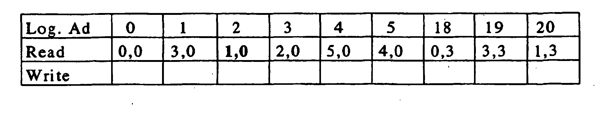

- The physical address 1,0 corresponding to the cluster containing the data sample with the logical address 2 is highlighted in the look-up table 11 above.
- The reordering buffer 8 is full, so its content is written in the SQ-1=2 last rows or clusters processed of the current cluster array:
de-interleaving memory array 2 :18 24 30 36 42 48 12 13 14 20 26 32 38 44 50 3 9 15 21 27 33 39 45 51 6 7 8 19 25 31 37 43 49 5 11 17 23 29 35 41 47 53 4 10 16 22 28 34 40 46 52
0 1 2
reordering buffer 8:
- The addresses of the SQ-1=2 written reordered cluster are not stored, because with these predetermined parameters (L,C,SQ) their place is known. This have been the first step of reordering. Now a cluster is free in the de-interleaving memory array 2, and the SQ first data samples of the next sequence to be de-interleaved is stored in:
de-interleaving memory array 2 :0 6 12 18 24 30 36 42 48 12 13 14 20 26 32 38 44 50 3 9 15 21 27 33 39 45 51 6 7 8 19 25 31 37 43 49 5 11 17 23 29 35 41 47 53 4 10 16 22 28 34 40 46 52
0 1 2
reordering buffer 8:
- So it is necessary to store in the look-up table the physical address of the first data sample of the cluster corresponding to these data of the next sequence:
look-up table 11:

- A second step of reordering begins so, with, as above described reading of clusters of the second square cluster array, with the logical addresses underlined, and with outputting the first data sample of the clusters, and writing others data samples in the columns of the reordering buffer 8:
de-interleaving memory array 2 :0 6 12 18 24 30 36 42 48 12 13 14 20 26 32 38 44 50 3 9 15 21 27 33 39 45 51 6 7 8 19 25 31 37 43 49 5 11 17 23 29 35 41 47 53 4 10 16 22 28 34 40 46 52
de-interleaving memory array 2 :0 6 12 18 24 30 36 42 48 12 13 14 20 26 32 38 44 50 21 27 33 39 45 51 6 7 8 19 25 31 37 43 49 23 29 35 41 47 53 22 28 34 40 46 52
3 4 5
reordering buffer 8:9 10 11 15 16 17 
- The physical addresses 2,0 ; 5,0 ; 4,0 corresponding to the cluster containing the data sample with the logical addresses 3 ; 4 ; 5 are highlighted in the look-up table 11 above.
- The content of the reordering buffer 8 is written in the SQ-1=2 last rows or clusters processed of the current cluster array:
de-interleaving memory array 2 :0 6 12 18 24 30 36 42 48 12 13 14 20 26 32 38 44 50 21 27 33 39 45 51 6 7 8 19 25 31 37 43 49 15 16 17 23 29 35 41 47 53 9 10 11 22 28 34 40 46 52 - The SQ next data samples of the next sequence are stored in the free cluster :
de-interleaving memory array 2 :0 6 12 18 24 30 36 42 48 12 13 14 20 26 32 38 44 50 18 24 30 21 27 33 39 45 51 6 7 8 19 25 31 37 43 49 15 16 17 23 29 35 41 47 53 9 10 11 22 28 34 40 46 52 
- These L/SQ=2 reordering steps are followed by L-L/SQ=4 steps without reordering, in each one the following cluster is output in a block, and the free cluster is written with the SQ=3 next data samples of the next sequence:
de-interleaving memory array 2 :0 6 12 18 24 30 36 42 48 19 25 31 20 26 32 38 44 50 18 24 30 21 27 33 39 45 51 36 42 48 19 25 31 37 43 49 37 43 49 23 29 35 41 47 53 1 7 13 22 28 34 40 46 52
6 7 8 9 10 11 12 13 14 15 16 17
reordering buffer 8:

- The method continues in the same way, cluster array by cluster array, until the first sequence have been de-interleaved, and then the next sequence is stored in the de-interleaving memory array 2.
- Of course, if de-interleaving memory array 2 is completed with padding data, the method is identical, and the padding data are than eliminated.
- The invention allows to avoid having adaptation buffers and to decrease the memory access rate.
- The invention also allows to have high-throughput application, and to avoid bottleneck.
- The invention is so a low power solution.
Claims (18)
- Method of de-interleaving successive sequences of interleaved data samples extracted from a virtual memory array having L0 columns and C0 rows, comprising the steps of:receiving each sequence of said interleaved data samples and writing row by row said received sequences of interleaved data samples in a de-interleaving memory array (2) having L rows and C columns, L being superior or equal to L0 and C being superior or equal to C0, andde-interleaving the data samples stored in said de-interleaving memory array (2) sub-array by sub-array, the used predetermined sub-array being a square cluster array having a predetermined number SQ of rows and of columns, the number L of rows and the number C of columns of the de-interleaving memory array (2) being multiples of the number SQ of rows and columns.
- Method according to claim 1, wherein, if L0 and C0 are not multiples of SQ, then said writing step comprises a step of completing the de-interleaving memory array (2) with padding data to have L rows and C columns, L and C being multiples of SQ.
- Method according to claim 1 or 2, wherein the square cluster array comprises consecutive or not consecutive clusters, along rows of the de-interleaving memory array (2), a cluster being a row of the square cluster array comprising SQ data samples.
- Method according to any one of claims 1 to 3, wherein a cluster being a row of the square cluster array comprising SQ data samples, said square cluster array by square cluster array de-interleaving step comprises, for a first group of clusters of the current square cluster array, reading each cluster of said first group, outputting the first data sample of the cluster, and reordering the other data samples of the cluster in a column of a reordering buffer (8) and writing back the data samples de-interleaved in said reordering buffer (8) into the de-interleaving memory at the last SQ-1 accessed clusters, and
for a second group of previously reordered clusters, reading each cluster of said second group and outputting all the data samples of the cluster. - Method according to claim 4, wherein said square cluster array by square cluster array de-interleaving comprises cyclically, C/SQ times, L/SQ consecutive processing with reordering of clusters and L-L/SQ consecutive processing without reordering of clusters.
- Method according to claim 4 or 5, wherein said reordering buffer (8) has SQ-1 rows and SQ columns.
- Method according to any one of claims 1 to 6, further comprising using a look-up table (11) having three rows and a number of columns equal to C×L/SQ, said look-up table (11) containing the logical addresses of some of the data samples of the current sequence of interleaved data samples and the corresponding physical addresses in said de-interleaving memory array (2).
- Method according to claim 7, wherein
the first row of the look-up table (11) stores the logical addresses of the data samples of interleaved data samples of the current sequence stored in the columns of the de-interleaving memory array (2) indexed p(i)+k×SQ, where p(i) specifies the inter-columns permutation, with i varying from 0 to L/SQ-1, and k varying from 0 to C/SQ-1,
the second row of the look-up table (11) stores physical addresses of the respective logical addresses of the first row, and
the third row of the look-up table (11) stores physical addresses of data samples of the next sequence of interleaved data samples to be written in the de-interleaving memory array (2), having the respective logical addresses of the first row. - Method according to claim 8, wherein said square cluster array by square cluster array de-interleaving step further comprises, after having processed a previous cluster, selecting, in the square cluster array, the next cluster having a first data sample having a logical address immediately following the logical address of the last sample of said previous cluster.
- De-interleaving device (1) of successive sequences of interleaved data sample for a receiving system, interleaved data samples being extracted from a virtual memory array having L0 columns and C0 rows, comprising a de-interleaving memory array (2), comprising
receiving means (3) for receiving each sequence of said interleaved data samples and writing means (4) for writing row by row said received sequences of interleaved data samples in said de-interleaving memory array (2) having L rows and C columns, L being superior or equal to L0 and C being superior or equal to C0, and
de-interleaving means (5) for de-interleaving the data samples stored in said de-interleaving memory array (2) sub-array by sub-array, the used predetermined sub-array being a square cluster array having a predetermined number SQ of rows and of columns, the number L of rows and the number C of columns of the de-interleaving memory array (2) being multiples of the number SQ of rows and columns. - De-interleaving device (1) according to claim 10, wherein said de-interleaving means (5) comprise completing means (6) for completing, if L0 and C0 are not multiples of SQ, said de-interleaving memory array (2) with padding data to have L rows and C columns, L and C being multiples of SQ.
- De-interleaving device (1) according to claim 10 or 11, wherein the square cluster array comprises consecutive or not consecutive clusters, a cluster being a row of said square cluster array comprising SQ data samples.
- De-interleaving device (1) according to any one of claims 10 to 12, further comprising a reordering buffer (8), and wherein de-interleaving means (5) comprise
first means (9) for reading each cluster of a first group of clusters of the current cluster array, a cluster being a row of said square cluster array comprising SQ data samples, outputting the first data sample of the cluster, and reordering the other data samples of the cluster in a column of the reordering buffer (8) and writing its content back at the SQ-1 last accessed clusters into the de-interleaving memory, and
second means (10) for reading each cluster of a second group of clusters of the current cluster array and outputting the cluster. - De-interleaving device (1) according to claim 13, wherein said reordering buffer (8) comprises SQ-1 rows and SQ columns.
- De-interleaving device (1) according to any one of claims 10 to 14, further to comprising a look-up table (11) comprising three rows and a number of columns equal to C×L/SQ, said look-up table (11) containing the logical addresses of some of the samples of the current sequence of interleaved data samples and the corresponding physical addresses in said de-interleaving memory array (2).
- De-interleaving device (1) according to claim 15, wherein said de-interleaving means (5) comprise:first storing means (12) for storing, in the first row of the look-up table (11), the logical addresses of the data samples of interleaved data samples of the current sequence stored in the columns of the de-interleaving memory array (2) indexed p(i)+k×SQ, where p(i) specifies the inter-columns permutation, with i varying from 0 to L/SQ-1, and k varying from 0 to C/SQ-1,second storing means (13) for storing, in the second row of the look-up table (11), physical addresses of the respective logical addresses of the first row, andthird storing means (14) for storing, in the third row of the look-up table (11), physical addresses of data samples of the next sequence of interleaved data samples to be written in the de-interleaving memory array (2), having the respective logical addresses of the first row.
- De-interleaving device (1) according to claim 16, wherein said de-interleaving means (5) comprise selecting means (15) for selecting, after having processed a previous cluster, in the square cluster array, the next cluster having a first data sample having a logical address immediately following the logical address of the last data sample of said previous cluster.
- Receiving apparatus, in particular a cellular mobile phone, characterized by the fact that it incorporates a de-interleaving device (1) as defined in any one of claims 10 to 17.
Priority Applications (3)
| Application Number | Priority Date | Filing Date | Title |
|---|---|---|---|
| EP03293074A EP1542368B1 (en) | 2003-12-09 | 2003-12-09 | Method and device of de-interleaving successive sequences of interleaved data samples |
| DE60322550T DE60322550D1 (en) | 2003-12-09 | 2003-12-09 | Method and apparatus for deinterleaving successive sequences of interlaced sample data |
| US11/007,785 US7370246B2 (en) | 2003-12-09 | 2004-12-08 | Method and device of de-interleaving successive sequences of interleaved data samples |
Applications Claiming Priority (1)
| Application Number | Priority Date | Filing Date | Title |
|---|---|---|---|
| EP03293074A EP1542368B1 (en) | 2003-12-09 | 2003-12-09 | Method and device of de-interleaving successive sequences of interleaved data samples |
Publications (2)
| Publication Number | Publication Date |
|---|---|
| EP1542368A1 EP1542368A1 (en) | 2005-06-15 |
| EP1542368B1 true EP1542368B1 (en) | 2008-07-30 |
Family
ID=34486447
Family Applications (1)
| Application Number | Title | Priority Date | Filing Date |
|---|---|---|---|
| EP03293074A Expired - Lifetime EP1542368B1 (en) | 2003-12-09 | 2003-12-09 | Method and device of de-interleaving successive sequences of interleaved data samples |
Country Status (3)
| Country | Link |
|---|---|
| US (1) | US7370246B2 (en) |
| EP (1) | EP1542368B1 (en) |
| DE (1) | DE60322550D1 (en) |
Families Citing this family (6)
| Publication number | Priority date | Publication date | Assignee | Title |
|---|---|---|---|---|
| US7477186B2 (en) * | 2005-10-11 | 2009-01-13 | Sony Ericsson Mobile Communications Ab | Memory systems with column read to an arithmetic operation circuit, pattern detector circuits and methods and computer program products for the same |
| KR101613893B1 (en) | 2007-10-04 | 2016-04-20 | 삼성전자주식회사 | Method and apparatus for interleaving data in mobile telecommunication system |
| US9712279B2 (en) | 2007-10-04 | 2017-07-18 | Samsung Electronics Co., Ltd. | Method and apparatus for interleaving data in a mobile communication system |
| US10203881B2 (en) * | 2011-12-19 | 2019-02-12 | Apple Inc. | Optimized execution of interleaved write operations in solid state drives |
| US10459803B2 (en) * | 2017-06-28 | 2019-10-29 | Western Digital Technologies, Inc. | Method for management tables recovery |
| US10879936B2 (en) * | 2018-08-23 | 2020-12-29 | Keysight Technologies, Inc. | Methods, systems, and computer readable media for de-interleaving data in a communication system |
Family Cites Families (9)
| Publication number | Priority date | Publication date | Assignee | Title |
|---|---|---|---|---|
| US5623459A (en) * | 1993-09-29 | 1997-04-22 | Sony Corporation | Method and apparatus for error correcting reproduced data |
| FR2713845B1 (en) * | 1993-12-07 | 1996-01-19 | Thomson Consumer Electronics | Block interleaving and deinterleaving method and implementation device. |
| JP3415693B2 (en) * | 1993-12-23 | 2003-06-09 | ノキア モービル フォーンズ リミテッド | Interleaving process |
| US5572532A (en) * | 1993-12-29 | 1996-11-05 | Zenith Electronics Corp. | Convolutional interleaver and deinterleaver |
| US5659578A (en) * | 1994-11-23 | 1997-08-19 | At&T Wireless Services, Inc. | High rate Reed-Solomon concatenated trellis coded 16 star QAM system for transmission of data over cellular mobile radio |
| JP3614907B2 (en) * | 1994-12-28 | 2005-01-26 | 株式会社東芝 | Data retransmission control method and data retransmission control system |
| US6553517B1 (en) * | 1999-04-09 | 2003-04-22 | Sony Corporation | Interleavers and de-interleavers |
| GB2361781B (en) * | 2000-04-25 | 2004-12-29 | Ubinetics Ltd | Interleaving and de-interleaving of telecommunications signals |
| US6603412B2 (en) * | 2001-06-08 | 2003-08-05 | Texas Instruments Incorporated | Interleaved coder and method |
-
2003
- 2003-12-09 DE DE60322550T patent/DE60322550D1/en not_active Expired - Lifetime
- 2003-12-09 EP EP03293074A patent/EP1542368B1/en not_active Expired - Lifetime
-
2004
- 2004-12-08 US US11/007,785 patent/US7370246B2/en active Active
Also Published As
| Publication number | Publication date |
|---|---|
| EP1542368A1 (en) | 2005-06-15 |
| US20050160342A1 (en) | 2005-07-21 |
| DE60322550D1 (en) | 2008-09-11 |
| US7370246B2 (en) | 2008-05-06 |
Similar Documents
| Publication | Publication Date | Title |
|---|---|---|
| JP3996514B2 (en) | Buffer architecture for turbo decoder | |
| US7640479B2 (en) | Single engine turbo decoder with single frame size buffer for interleaving/deinterleaving | |
| EP1650873B1 (en) | Turbo decoding apparatus and interleave-deinterleave apparatus | |
| KR100898467B1 (en) | Method and apparatus for encoding data in parallel | |
| EP1317804B1 (en) | Data buffer structure for asynchronously received physical channels in a cdma system | |
| EP1264409B1 (en) | Interleaver and method for interleaving an input data bit sequence using a coded storing of symbol and additional information | |
| US7814388B2 (en) | System and method for interleaving data in a wireless transmitter | |
| US7139862B2 (en) | Interleaving method and apparatus with parallel access in linear and interleaved order | |
| JP2010093832A (en) | Block interleaving for turbo coding | |
| EP1695443B1 (en) | Multi-standard turbo interleaver using tables | |
| EP1542368B1 (en) | Method and device of de-interleaving successive sequences of interleaved data samples | |
| JP2003504933A (en) | Address generator for use in a multi-stage channel interleaver / deinterleaver | |
| US20050248473A1 (en) | Speed and memory optimised interleaving | |
| EP2422452A1 (en) | Data rearrangement for decoder | |
| WO2001031869A1 (en) | Cache and caching method for convolutional decoders | |
| KR20110068103A (en) | Data derate matcher capable of providing harq and method thereof | |
| KR100628201B1 (en) | Method for Turbo Decoding | |
| KR20090044178A (en) | Method and apparatus for paraller structured latin square interleaving in communication system | |
| US7111207B2 (en) | Error-correcting communication method and communication apparatus with de-interleaving and rate de-matching | |
| KR20010080700A (en) | Interleave address generating device and interleave address generating method | |
| US10270473B2 (en) | Turbo decoders with stored column indexes for interleaver address generation and out-of-bounds detection and associated methods | |
| US6198733B1 (en) | Forward-link sync-channel interleaving/de-interleaving for communication systems based on closed-form expressions | |
| EP1529344A2 (en) | Method of first interleavering of a two interleaver transmitter | |
| EP1542369A1 (en) | Method and system for de-interleaving of data | |
| CN117978326A (en) | Signal de-interleaving method and system for 5G-NR system |
Legal Events
| Date | Code | Title | Description |
|---|---|---|---|
| PUAI | Public reference made under article 153(3) epc to a published international application that has entered the european phase |
Free format text: ORIGINAL CODE: 0009012 |
|
| AK | Designated contracting states |
Kind code of ref document: A1 Designated state(s): AT BE BG CH CY CZ DE DK EE ES FI FR GB GR HU IE IT LI LU MC NL PT RO SE SI SK TR |
|
| AX | Request for extension of the european patent |
Extension state: AL LT LV MK |
|
| 17P | Request for examination filed |
Effective date: 20051124 |
|
| AKX | Designation fees paid |
Designated state(s): DE FR GB IT |
|
| GRAP | Despatch of communication of intention to grant a patent |
Free format text: ORIGINAL CODE: EPIDOSNIGR1 |
|
| GRAS | Grant fee paid |
Free format text: ORIGINAL CODE: EPIDOSNIGR3 |
|
| GRAA | (expected) grant |
Free format text: ORIGINAL CODE: 0009210 |
|
| AK | Designated contracting states |
Kind code of ref document: B1 Designated state(s): DE FR GB IT |
|
| REG | Reference to a national code |
Ref country code: GB Ref legal event code: FG4D |
|
| REF | Corresponds to: |
Ref document number: 60322550 Country of ref document: DE Date of ref document: 20080911 Kind code of ref document: P |
|
| PLBE | No opposition filed within time limit |
Free format text: ORIGINAL CODE: 0009261 |
|
| STAA | Information on the status of an ep patent application or granted ep patent |
Free format text: STATUS: NO OPPOSITION FILED WITHIN TIME LIMIT |
|
| 26N | No opposition filed |
Effective date: 20090506 |
|
| PG25 | Lapsed in a contracting state [announced via postgrant information from national office to epo] |
Ref country code: IT Free format text: LAPSE BECAUSE OF FAILURE TO SUBMIT A TRANSLATION OF THE DESCRIPTION OR TO PAY THE FEE WITHIN THE PRESCRIBED TIME-LIMIT Effective date: 20080730 |
|
| PGFP | Annual fee paid to national office [announced via postgrant information from national office to epo] |
Ref country code: GB Payment date: 20101201 Year of fee payment: 8 |
|
| PGFP | Annual fee paid to national office [announced via postgrant information from national office to epo] |
Ref country code: DE Payment date: 20101208 Year of fee payment: 8 Ref country code: FR Payment date: 20110120 Year of fee payment: 8 |
|
| GBPC | Gb: european patent ceased through non-payment of renewal fee |
Effective date: 20111209 |
|
| REG | Reference to a national code |
Ref country code: FR Ref legal event code: ST Effective date: 20120831 |
|
| REG | Reference to a national code |
Ref country code: DE Ref legal event code: R119 Ref document number: 60322550 Country of ref document: DE Effective date: 20120703 |
|
| PG25 | Lapsed in a contracting state [announced via postgrant information from national office to epo] |
Ref country code: GB Free format text: LAPSE BECAUSE OF NON-PAYMENT OF DUE FEES Effective date: 20111209 Ref country code: DE Free format text: LAPSE BECAUSE OF NON-PAYMENT OF DUE FEES Effective date: 20120703 |
|
| PG25 | Lapsed in a contracting state [announced via postgrant information from national office to epo] |
Ref country code: FR Free format text: LAPSE BECAUSE OF NON-PAYMENT OF DUE FEES Effective date: 20120102 |