EP1542213A2 - Optical pickup actuator - Google Patents
Optical pickup actuator Download PDFInfo
- Publication number
- EP1542213A2 EP1542213A2 EP04028190A EP04028190A EP1542213A2 EP 1542213 A2 EP1542213 A2 EP 1542213A2 EP 04028190 A EP04028190 A EP 04028190A EP 04028190 A EP04028190 A EP 04028190A EP 1542213 A2 EP1542213 A2 EP 1542213A2
- Authority
- EP
- European Patent Office
- Prior art keywords
- lens
- magnets
- optical pickup
- pickup actuator
- disc
- Prior art date
- Legal status (The legal status is an assumption and is not a legal conclusion. Google has not performed a legal analysis and makes no representation as to the accuracy of the status listed.)
- Granted
Links
Images




Classifications
-
- G—PHYSICS
- G11—INFORMATION STORAGE
- G11B—INFORMATION STORAGE BASED ON RELATIVE MOVEMENT BETWEEN RECORD CARRIER AND TRANSDUCER
- G11B7/00—Recording or reproducing by optical means, e.g. recording using a thermal beam of optical radiation by modifying optical properties or the physical structure, reproducing using an optical beam at lower power by sensing optical properties; Record carriers therefor
- G11B7/08—Disposition or mounting of heads or light sources relatively to record carriers
- G11B7/09—Disposition or mounting of heads or light sources relatively to record carriers with provision for moving the light beam or focus plane for the purpose of maintaining alignment of the light beam relative to the record carrier during transducing operation, e.g. to compensate for surface irregularities of the latter or for track following
-
- G—PHYSICS
- G11—INFORMATION STORAGE
- G11B—INFORMATION STORAGE BASED ON RELATIVE MOVEMENT BETWEEN RECORD CARRIER AND TRANSDUCER
- G11B7/00—Recording or reproducing by optical means, e.g. recording using a thermal beam of optical radiation by modifying optical properties or the physical structure, reproducing using an optical beam at lower power by sensing optical properties; Record carriers therefor
- G11B7/08—Disposition or mounting of heads or light sources relatively to record carriers
- G11B7/09—Disposition or mounting of heads or light sources relatively to record carriers with provision for moving the light beam or focus plane for the purpose of maintaining alignment of the light beam relative to the record carrier during transducing operation, e.g. to compensate for surface irregularities of the latter or for track following
- G11B7/0925—Electromechanical actuators for lens positioning
- G11B7/0935—Details of the moving parts
-
- G—PHYSICS
- G11—INFORMATION STORAGE
- G11B—INFORMATION STORAGE BASED ON RELATIVE MOVEMENT BETWEEN RECORD CARRIER AND TRANSDUCER
- G11B7/00—Recording or reproducing by optical means, e.g. recording using a thermal beam of optical radiation by modifying optical properties or the physical structure, reproducing using an optical beam at lower power by sensing optical properties; Record carriers therefor
- G11B7/08—Disposition or mounting of heads or light sources relatively to record carriers
- G11B7/09—Disposition or mounting of heads or light sources relatively to record carriers with provision for moving the light beam or focus plane for the purpose of maintaining alignment of the light beam relative to the record carrier during transducing operation, e.g. to compensate for surface irregularities of the latter or for track following
- G11B7/0925—Electromechanical actuators for lens positioning
- G11B7/0933—Details of stationary parts
-
- G—PHYSICS
- G11—INFORMATION STORAGE
- G11B—INFORMATION STORAGE BASED ON RELATIVE MOVEMENT BETWEEN RECORD CARRIER AND TRANSDUCER
- G11B7/00—Recording or reproducing by optical means, e.g. recording using a thermal beam of optical radiation by modifying optical properties or the physical structure, reproducing using an optical beam at lower power by sensing optical properties; Record carriers therefor
- G11B2007/0003—Recording, reproducing or erasing systems characterised by the structure or type of the carrier
- G11B2007/0006—Recording, reproducing or erasing systems characterised by the structure or type of the carrier adapted for scanning different types of carrier, e.g. CD & DVD
Definitions
- the present invention relates to an optical pickup actuator, in which a pair of lenses, e.g., BD lens and DVD lens, are loaded on one pickup to record/reproduce information on/from optical discs having various write capacities such as BD (Blu-ray disc), CD, DVD and the like, by which drive and system configurations can be simplified, and by which the facilitation of the system configuration and high sensitivity of the actuator are provided since there exist no sensitivity deviations of tracking and focusing between BD and CD/DVD actuators.
- BD Blu-ray disc
- DVD digital versatile disc
- HD high definition moving picture information
- BD Blu-ray disc
- NA numerical aperture
- BD uses a high-NA lens designed to have a focus fitted on a recording surface of 0.1mm thickness
- compatibility problem in using the BD lens for another optical disc such as CD, DVD, or the like, which has a recording surface thickness different from that of BD.
- SA spherical aberration
- CA coma aberration
- AS astigmatism
- the lens for CD or DVD is also needed in addition to the lens for BD for securing compatibility with various kinds of optical discs due to such a problem as the difference of optical power (write power) and the like.
- a pair of optical pickups are loaded on one drive in a manner of configuring separately the DVD or CD optical pickup and the BD optical pickup.
- the present invention is directed to an optical pickup actuator that substantially obviates one or more problems due to limitations and disadvantages of the related art.
- An object of the present invention is to provide an optical pickup actuator, in which a pair of lenses, e.g., BD lens and DVD lens, are loaded on one pickup to record/reproduce information on/from optical discs having various write capacities such as BD (Blu-ray disc), CD, DVD and the like, by which drive and system configurations can be simplified, and by which the facilitation of the system configuration and high sensitivity of the actuator are provided since there exit no sensitivity deviations of tracking and focusing between BD and CD/DVD actuators.
- BD Blu-ray disc
- an optical pickup actuator comprises a yoke comprising a plate member and four magnet guides protruding from a lateral side of the plate member in a direction vertical to a topside of the plate member and configuring two confronting pairs with each magnet guide left a prescribed distance from adjacent magnetic guides, first to fourth magnets adhering closely to insides of the magnet guides, respectively to provide an inside space on the plate member of the yoke, a shaft protruding from the plate member of the yoke within the inside space surrounded by the first to fourth magnets, a lens holder loaded on the plate member of the yoke within the inside space surrounded by the first to fourth magnets to have the shaft inserted therein and to have first and second disc lenses provided thereon, iron piece guides protruding from a lateral side of the lens holder to confront the first to fourth magnets and to have recesses inside, respectively, first to
- an optical pickup actuator comprises a first and third magnets confronting to leave a prescribed distance from each other wherein each of the first and third magnets is divided into right and left parts differing from each other in polarity, a second and fourth magnets confronting to leave a prescribed distance from each other on a line crossing with a connecting line between the first and third magnets wherein each of the second and fourth magnets is divided into upper and lower parts differing from each other in polarity, a pair of first conductive coils provided to an inside area of a closed curve line sequentially connecting the first to fourth magnets to separately lie on the connecting line between the first and third magnets, a pair of the first conductive coils wound on iron pieces, respectively, a pair of second conductive coils provided to the inside area of the closed curve line sequentially connecting the first to fourth magnets to separately lie on a connecting line between the second and fourth magnets, a pair of the second conductive coils wound on iron pieces, respectively, and a lens holder having a first and second disc
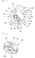
- FIG. 1 is a projected perspective diagram of an optical pickup actuator according to the present invention.
- an optical pickup actuator comprises a yoke 100 comprising a plate member 110 and four magnet guides 121 to 124 protruding from a lateral side of the plate member 110 in a direction vertical to a topside of the plate member 110 and configuring two confronting pairs with each magnet guide left a prescribed distance from adjacent magnetic guides, first to fourth magnets 131 to 134 adhering closely to insides of the magnet guides 121 to 124, respectively to provide an inside space on the plate member 110 of the yoke 100, a shaft 151 protruding from the plate member 110 of the yoke 100 within the inside space surrounded by the first to fourth magnets 131 to 134, a lens holder 200 loaded on the plate member 110 of the yoke 100 within the inside space surrounded by the first to fourth magnets 131 to 134 to have the shaft 151 inserted therein and to have DVD and BD lenses provided thereon, iron piece guides 205 protruding from a lateral side of the lens holder
- first and second disc lenses are loaded on the lens holder 200.
- Each of the first and second lenses is to be selected from the group consisting of CD lens, DVD lens, CD/DVD lens, and BD lens.
- each of the first and second lenses is to be selected from the group consisting of blue light source lens, blue purple light source lens, and red light source lens.
- a shaft guide 230 having a perforated hole inside is provided within the lens holder 200 so that the shaft 151 can be inserted therein. Hence, the shaft 151 is inserted in the perforated hole of the shaft guide 230 so that the lens holder 200, as shown in FIG. 2, can be assembled to the yoke 100.
- each of the iron guides 205 has a rectangular shape having a recess inside or a ' ' shape having one side open.
- a reference number '170' in FIG. 2 indicates a printed circuit board (PCB) connected to the coils.
- PCB printed circuit board
- the magnet guides 121 and 123 confront each other to configure one pair, while the rest magnet guides 122 and 124 confront each other to configure the other pair. Hence, there are two pairs of the magnet guides 121 to 124.
- FIG. 3 is a diagram of an optical pickup actuator according to the present invention for explaining tracking and focusing operations of reproducing/writing information from/on CD or DVD.
- the first and third magnets 131 and 133 each of which is divided into right and left parts to differ from each other in polarity, are provided to the yoke 100.
- the second and fourth magnets 132 and 134 each of which is divided into upper and lower parts to differ from each other in polarity, are provided to the yoke 100 as well.
- the coils 221 and 223 wound on the first and third iron pieces of the lens holder 200 are placed to confront the first and third magnets 131 and 133, respectively. And, the rest coils 222 and 224 wound on the second and fourth iron pieces of the lens holder 200 are placed to confront the second and fourth magnets 132 and 134, respectively.
- a positive voltage is applied to the coil 223 wound on the third iron piece and a negative voltage is applied to the coil 221 wound on the first iron piece.
- the CD or DVD lens tracks in a direction of an inner circumference of a disc.
- the CD or DVD lens tracks in a direction of an outer circumference of a disc.
- a positive voltage is applied to the coil 224 wound on the fourth iron piece and a negative voltage is applied to the coil 222 wound on the second iron piece.
- the CD or DVD lens is raised to get closer to the disc.
- FIG. 4 is a diagram of an optical pickup actuator according to the present invention for explaining tracking and focusing operations of reproducing/writing information from/on BD.
- the lens holder 200 is rotated by 90° centering on the shaft.
- the coils 221 and 223 wound on the first and third iron pieces used in the CD or DVD tracking are used as BD focusing coils, respectively, by 90° rotation of the lens holder 200, while the rest coils 222 and 224 wound on the second and fourth iron pieces used in the CD or DVD focusing are used as BD tracking coils, respectively, by 90° rotation of the lens holder 200.
- the BD tracking/focusing is carried out in the same manner as the CD or DVD tracking/focusing.
- the present invention makes it possible to utilize two lenses in one lens holder.
- the present invention reduces the overall weight to enhance sensitivity. And, since the iron pieces are assembled to the outer lateral side of the lens holder, the present invention enhances assembly efficiency as well as reduces assembly deviation.
- FIG. 5A and FIG. 5B are diagrams of an optical pickup actuator according to the present invention, in which a coil and iron piece confront a magnet in tracking or focusing each.
- the magnets and the iron pieces used in the optical pickup actuator of the present invention are uniform in size, thereby reducing the deviation in switching.
- a symmetric center line of the iron piece 210 coincides with an area having the greatest magnetic forces of other magnets differing in polarity each, i.e., a separated line (magnetic gap) according to a force stabilizing the iron piece 210 toward the area having the greatest magnetic forces of the magnets 131a/131b and 132a/132b differing in polarity each.
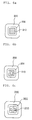
- FIGs. 6A to 6C are diagrams of an iron piece according to the present invention.
- the iron pieces can be variously shaped according to the spring constant value needed by a system.
- the iron piece as shown in FIG. 6A, is rectangular.
- FIG. 7 is a diagram of an optical pickup actuator according to the present invention for explaining a switching principle of a lens.
- a BD lens 302 is rotated by 90° to be moved to a position where the CD or DVD lens 301 used to be placed.
- a switching angle ⁇ 1 between the CD/DVD lens 301 and the BD lens 302 should be equal to an angle ⁇ 2 between two neighboring iron pieces or magnets.
- the angle is determined as 90°.
- FIG. 8 is a perspective diagram of a rotation blocking rod used in lens switching according to the present invention.
- a blocking rod 231 is provided to a lateral side of the lens holder shaft guide 230 having the perforated hole in which the shaft of the yoke is inserted.
- a rotation preventing block 150 is provided to the yoke 100 to prevent the blocking rod 231 from being rotated over 90°.
- the blocking rod 231 and the rotation preventing block 150 are able to prevent the lens from being rotated over 90°.
- FIG. 10A and FIG. 10B are perspective diagrams of a sidewall of a lens holder for sensing positions of CD or DVD lens and BD lens according to the present invention.
- a sidewall 270 of the lens holder in the vicinity of the CD or DVD lens 301 is fully closed to recognize that the CD or DVD lens 301 is located at the position for performing reproduction and recording.
- a sidewall 270 of the lens holder in the vicinity of the BD lens 302 is partially open to recognize that the BD lens 302 is located at the position for performing reproduction and recording.
- the sidewalls of the lens holder are configured to be fully closed and partially open, respectively, by the difference of current flowing into a position deciding sensor (indicated by a reference number 601 in FIG. 3, FIG. 4, or FIG. 7) it is possible to recognize the position of the CD/DVD lens 301 or the BD lens 302.
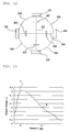
- a distance of the partially open sidewall state 'b' of the lens holder is longer than that of the fully closed sidewall state 'a' of the lens holder as shown in FIG. 13.
- 'a' in FIG. 13 represents the case that the sidewall of the lens holder is fully closed, in which an output voltage corresponding to the distance of the light traveling to return measures 4V in case of the distance 2mm.
- 'b' in FIG. 13 represents the case that the sidewall of the lens holder is partially open, in which an output voltage corresponding to the distance of the light traveling to return measures 2V in case of the distance 9mm.
- FIG. 11 is a schematic layout of a basic configuration of an optical pickup actuator according to the present invention
- FIG. 12 is a layout of magnets provided to an optical pickup actuator according to the present invention for explaining positions of the magnets.
- the concept of the present invention is applicable to a third equivalent disc-type recording medium as well as the CD, DVD, and BD.
- basic configurations will be explained with reference to the layout of FIG. 11 and conceptional diagram of FIG. 12.
- an optical pickup actuator comprises a first and third magnets 131 and 133 confronting to leave a prescribed distance from each other wherein each of the first and third magnets 131 and 133 is divided into right and left parts differing from each other in polarity, a second and fourth magnets 132 and 134 confronting to leave a prescribed distance from each other on a line crossing with a connecting line 501 between the first and third magnets 131 and 133 wherein each of the second and fourth magnets is divided into upper and lower parts differing from each other in polarity, a pair of first conductive coils 421 and 423 provided to an inside area of a closed curve line 510 sequentially connecting the first to fourth magnets 131 to 134 to separately lie on the connecting line 501 between the first and third magnets 131 and 133, a pair of the first conductive coils 421 and 423 wound on iron pieces, respectively, a pair of second conductive coils 422 and 424 provided to the inside area of the closed curve line 510 sequentially
- the first to fourth magnets are separated from each other by 90° each and the lens holder 250 is rotated by 90° centering on its center.
- the present invention loads a pair of lenses, e.g., BD lens and DVD lens, on one pickup to record/reproduce information on/from optical discs having various write capacities such as BD (Blu-ray disc), CD, DVD and the like, by which drive and system configurations can be simplified and by which the facilitation of the system configuration and high sensitivity of the actuator are provided since there exist no sensitivity deviations of tracking and focusing between BD and CD/DVD actuators.
- BD Blu-ray disc
Landscapes
- Optical Recording Or Reproduction (AREA)
- Optical Head (AREA)
- Studio Devices (AREA)
Abstract
Description

Claims (19)
- An optical pickup actuator comprising:a yoke comprising a plate member and four magnet guides protruding from a lateral side of the plate member in a direction vertical to a topside of the plate member and configuring two confronting pairs with each magnet guide left a prescribed distance from adjacent magnetic guides;first to fourth magnets adhering closely to insides of the magnet guides, respectively to provide an inside space on the plate member of the yoke;a shaft protruding from the plate member of the yoke within the inside space surrounded by the first to fourth magnets;a lens holder loaded on the plate member of the yoke within the inside space surrounded by the first to fourth magnets to have the shaft inserted therein and to have first and second disc lenses provided thereon;iron piece guides protruding from a lateral side of the lens holder to confront the first to fourth magnets and to have recesses inside, respectively;first to fourth iron pieces fitted in the recesses of the iron piece guides, respectively; andcoils wound on outsides of the iron piece guides, respectively.
- The optical pickup actuator of claim 1, wherein the first disc lens is selected from the group consisting of a CD lens, a DVD lens, and a CD/DVD lens and wherein the second disc lens is a BD lens.
- The optical pickup actuator of claim 1, wherein the first disc lens is a red light source lens and wherein the second disc lens is selected from the group consisting of a blue light source lens and a blue purple light source lens.
- The optical pickup actuator of claim 1, wherein a shaft guide having a perforated hole inside is provided within the lens holder so that the shaft can be inserted in the perforated hole.
- The optical pickup actuator of claim 1, wherein the first and third magnets, each of which is divided into right and left parts to differ from each other in polarity, confront each other and wherein the second and fourth magnets, each of which is divided into upper and lower parts to differ from each other in polarity, confront each other.
- The optical pickup actuator of claim 1, wherein the lens holder is rotated by 90° centering on the shaft for switching the first and second disc lenses.
- The optical pickup actuator of claim 1, wherein the neighboring iron pieces or magnets are separated from each other by 90°.
- The optical pickup actuator of claim 1, wherein if voltages are applied to the coils wound on the first to fourth iron pieces, tracking or focusing of the first and second disc lenses is carried out.
- The optical pickup actuator of claim 8, wherein the magnets or the iron pieces are uniform in size and wherein if the iron piece is placed to confront the corresponding magnet for the tracking or the focusing, a symmetric center line of the iron piece coincides with a separated line of magnet parts differing from each other in polarity by a force stabilizing the iron piece according to magnetic forces of the magnet parts.
- The optical pickup actuator of claim 4, wherein in order for the lens holder not to rotate over 90° for the switching of the first or second disc lens, a blocking rod is provided to a lateral side of the lens holder shaft guide having the perforated hole in which the shaft of the yoke is inserted and wherein a rotation preventing block is provided to the yoke to prevent the blocking rod from being rotated over 90°.
- The optical pickup actuator of claim 1, wherein a sidewall of the lens holder in the vicinity of the first disc lens is fully closed to recognize that the first disc lens is located at a position for performing reproduction and recording and wherein a sidewall of the lens holder in the vicinity of the second disc lens is partially open to recognize that the second disc lens is located at the position for performing the reproduction and recording.
- The optical pickup actuator of claim 1, wherein each of the iron pieces has a shape selected from the group consisting of a square shape, a square shape having an open inside, and a cross shape.
- An optical pickup actuator comprising:a first and third magnets confronting to leave a prescribed distance from each other wherein each of the first and third magnets is divided into right and left parts differing from each other in polarity;a second and fourth magnets confronting to leave a prescribed distance from each other on a line crossing with a connecting line between the first and third magnets wherein each of the second and fourth magnets is divided into upper and lower parts differing from each other in polarity;a pair of first conductive coils provided to an inside area of a closed curve line sequentially connecting the first to fourth magnets to separately lie on the connecting line between the first and third magnets, a pair of the first conductive coils wound on iron pieces, respectively;a pair of second conductive coils provided to the inside area of the closed curve line sequentially connecting the first to fourth magnets to separately lie on a connecting line between the second and fourth magnets, a pair of the second conductive coils wound on iron pieces, respectively; anda lens holder having a first and second disc lenses loaded thereon wherein the first and second conductive coils are provided to the lens holder.
- The optical pickup actuator of claim 13, wherein the first to fourth magnets are separated from each other by 90° each.
- The optical pickup actuator of claim 13, wherein if voltages differing in polarity are applied to a pair of the first conductive coils, respectively, a tracking operation of the first disc lens is carried out.
- The optical pickup actuator of claim 13, wherein if voltages differing in polarity are applied to a pair of the second conductive coils, respectively, a focusing operation of the first disc lens is carried out.
- The optical pickup actuator of claim 15, wherein if voltages differing in polarity are applied to a pair of the first conductive coils, respectively after completion of rotating the lens holder by 90°, a focusing operation of the second disc lens is carried out.
- The optical pickup actuator of claim 16, wherein if voltages differing in polarity are applied to a pair of the second conductive coils, respectively after completion of rotating the lens holder by 90°, a tracking operation of the second disc lens is carried out.
- The optical pickup actuator of claim 13, wherein the first disc lens is selected from the group consisting of a CD lens, a DVD lens, and a CD/DVD lens and wherein the second disc lens is a BD (Blu-ray disc) lens.
Applications Claiming Priority (2)
| Application Number | Priority Date | Filing Date | Title |
|---|---|---|---|
| KR1020030088556A KR100540146B1 (en) | 2003-12-08 | 2003-12-08 | Optical pickup actuator |
| KR2003088556 | 2003-12-08 |
Publications (3)
| Publication Number | Publication Date |
|---|---|
| EP1542213A2 true EP1542213A2 (en) | 2005-06-15 |
| EP1542213A3 EP1542213A3 (en) | 2006-03-29 |
| EP1542213B1 EP1542213B1 (en) | 2007-11-14 |
Family
ID=34511183
Family Applications (1)
| Application Number | Title | Priority Date | Filing Date |
|---|---|---|---|
| EP04028190A Expired - Lifetime EP1542213B1 (en) | 2003-12-08 | 2004-11-26 | Optical pickup actuator |
Country Status (5)
| Country | Link |
|---|---|
| US (1) | US7372786B2 (en) |
| EP (1) | EP1542213B1 (en) |
| KR (1) | KR100540146B1 (en) |
| CN (1) | CN1292420C (en) |
| DE (1) | DE602004010041T2 (en) |
Cited By (3)
| Publication number | Priority date | Publication date | Assignee | Title |
|---|---|---|---|---|
| EP1760703A3 (en) * | 2005-09-01 | 2007-04-18 | Samsung Electronics Co, Ltd | Optical pickup device |
| US7458087B2 (en) * | 2002-11-15 | 2008-11-25 | Samsung Electronics Co., Ltd. | Optical pickup actuator for reducing vibration |
| CN101650464B (en) * | 2008-08-14 | 2012-06-20 | 鸿富锦精密工业(深圳)有限公司 | Assembling device |
Families Citing this family (7)
| Publication number | Priority date | Publication date | Assignee | Title |
|---|---|---|---|---|
| KR100540146B1 (en) * | 2003-12-08 | 2006-01-12 | 엘지전자 주식회사 | Optical pickup actuator |
| TWI274926B (en) * | 2005-05-27 | 2007-03-01 | Powergate Optical Inc | A suspension apparatus for auto-focus lens device and a method for fabricating the same |
| US7725014B2 (en) * | 2007-08-29 | 2010-05-25 | Hong Kong Applied Science and Technology Research Institute Company Limited | Actuator for linear motion and tilting motion |
| CN109983677A (en) * | 2016-11-16 | 2019-07-05 | 松下知识产权经营株式会社 | Actuator and camera apparatus |
| USD851146S1 (en) | 2017-05-02 | 2019-06-11 | Johnson Controls Technology Company | Actuator |
| USD843425S1 (en) * | 2017-05-05 | 2019-03-19 | Higbie, LLC | Rotary actuator |
| JP1610448S (en) * | 2017-08-31 | 2018-08-06 |
Family Cites Families (11)
| Publication number | Priority date | Publication date | Assignee | Title |
|---|---|---|---|---|
| JP3805843B2 (en) * | 1995-11-10 | 2006-08-09 | 株式会社東芝 | Objective lens drive |
| US5966354A (en) * | 1995-11-10 | 1999-10-12 | Kabushiki Kaisha Toshiba | Drive apparatus for objective lens |
| US5864523A (en) * | 1995-11-10 | 1999-01-26 | Kabushiki Kaisha Toshiba | Objective lens driving apparatus |
| JPH09288835A (en) * | 1996-02-23 | 1997-11-04 | Matsushita Electric Ind Co Ltd | Objective lens drive |
| JP2874641B2 (en) | 1996-04-19 | 1999-03-24 | 日本電気株式会社 | Objective lens drive |
| KR19990028810A (en) * | 1996-05-09 | 1999-04-15 | 이데이 노부유끼 | Optical pickup and disc player |
| JPH10198969A (en) * | 1997-01-13 | 1998-07-31 | Toshiba Corp | Objective lens driving device and information processing device provided with this driving device |
| TW360400U (en) * | 1997-10-30 | 1999-06-01 | Ind Tech Res Inst | Magnetic floating actuator |
| JPH11175996A (en) * | 1997-12-15 | 1999-07-02 | Sony Corp | Objective lens drive mechanism and optical head |
| KR20010112774A (en) | 2000-06-15 | 2001-12-22 | 구자홍 | Lens actuator for pick-up |
| KR100540146B1 (en) * | 2003-12-08 | 2006-01-12 | 엘지전자 주식회사 | Optical pickup actuator |
-
2003
- 2003-12-08 KR KR1020030088556A patent/KR100540146B1/en not_active Expired - Fee Related
-
2004
- 2004-11-26 DE DE602004010041T patent/DE602004010041T2/en not_active Expired - Lifetime
- 2004-11-26 EP EP04028190A patent/EP1542213B1/en not_active Expired - Lifetime
- 2004-12-07 US US11/007,540 patent/US7372786B2/en not_active Expired - Fee Related
- 2004-12-08 CN CNB2004100965951A patent/CN1292420C/en not_active Expired - Fee Related
Cited By (3)
| Publication number | Priority date | Publication date | Assignee | Title |
|---|---|---|---|---|
| US7458087B2 (en) * | 2002-11-15 | 2008-11-25 | Samsung Electronics Co., Ltd. | Optical pickup actuator for reducing vibration |
| EP1760703A3 (en) * | 2005-09-01 | 2007-04-18 | Samsung Electronics Co, Ltd | Optical pickup device |
| CN101650464B (en) * | 2008-08-14 | 2012-06-20 | 鸿富锦精密工业(深圳)有限公司 | Assembling device |
Also Published As
| Publication number | Publication date |
|---|---|
| KR20050055354A (en) | 2005-06-13 |
| CN1292420C (en) | 2006-12-27 |
| CN1627390A (en) | 2005-06-15 |
| EP1542213B1 (en) | 2007-11-14 |
| DE602004010041D1 (en) | 2007-12-27 |
| EP1542213A3 (en) | 2006-03-29 |
| DE602004010041T2 (en) | 2008-09-11 |
| US20050122855A1 (en) | 2005-06-09 |
| KR100540146B1 (en) | 2006-01-12 |
| US7372786B2 (en) | 2008-05-13 |
Similar Documents
| Publication | Publication Date | Title |
|---|---|---|
| US7835253B2 (en) | Actuator having a plurality of objective lenses installed in a lens holder used with an optical pickup | |
| EP1542213B1 (en) | Optical pickup actuator | |
| US7458086B2 (en) | Actuator used with an optical pickup | |
| US7668049B2 (en) | Optical pickup actuator and optical recording/reproducing apparatus | |
| EP1600960B1 (en) | Optical pick-up actuator and method, and reproducing and/or recording apparatus with same | |
| US7643386B2 (en) | Optical pickup actuator and optical recording and/or reproducing apparatus | |
| KR100689042B1 (en) | Actuators and optical recording and / or reproducing apparatus for optical pickup | |
| KR100689035B1 (en) | Actuators and optical recording and / or reproducing apparatus for optical pickup | |
| US7453656B2 (en) | Recording and/or reproducing apparatus with an optical pickup actuator having high thrust | |
| KR100488039B1 (en) | Optical pick-up actuator | |
| KR100479617B1 (en) | Optical pick-up actuator | |
| US6084726A (en) | Optical pickup actuator for both a compact disc and a digital video disc | |
| KR100630774B1 (en) | High magnetic force circuit and optical pickup actuator using the magnetic circuit | |
| KR100220965B1 (en) | A tracking apparatus of actuator | |
| US20060262703A1 (en) | Optical pick-up actuator and optical recording and/or reproducing apparatus including the optical pick-up actuator |
Legal Events
| Date | Code | Title | Description |
|---|---|---|---|
| PUAI | Public reference made under article 153(3) epc to a published international application that has entered the european phase |
Free format text: ORIGINAL CODE: 0009012 |
|
| 17P | Request for examination filed |
Effective date: 20041127 |
|
| AK | Designated contracting states |
Kind code of ref document: A2 Designated state(s): AT BE BG CH CY CZ DE DK EE ES FI FR GB GR HU IE IS IT LI LU MC NL PL PT RO SE SI SK TR |
|
| AX | Request for extension of the european patent |
Extension state: AL HR LT LV MK YU |
|
| PUAL | Search report despatched |
Free format text: ORIGINAL CODE: 0009013 |
|
| AK | Designated contracting states |
Kind code of ref document: A3 Designated state(s): AT BE BG CH CY CZ DE DK EE ES FI FR GB GR HU IE IS IT LI LU MC NL PL PT RO SE SI SK TR |
|
| AX | Request for extension of the european patent |
Extension state: AL HR LT LV MK YU |
|
| AKX | Designation fees paid |
Designated state(s): DE GB NL |
|
| 17Q | First examination report despatched |
Effective date: 20061127 |
|
| GRAP | Despatch of communication of intention to grant a patent |
Free format text: ORIGINAL CODE: EPIDOSNIGR1 |
|
| GRAS | Grant fee paid |
Free format text: ORIGINAL CODE: EPIDOSNIGR3 |
|
| GRAA | (expected) grant |
Free format text: ORIGINAL CODE: 0009210 |
|
| AK | Designated contracting states |
Kind code of ref document: B1 Designated state(s): DE GB NL |
|
| REG | Reference to a national code |
Ref country code: GB Ref legal event code: FG4D |
|
| REF | Corresponds to: |
Ref document number: 602004010041 Country of ref document: DE Date of ref document: 20071227 Kind code of ref document: P |
|
| PLBE | No opposition filed within time limit |
Free format text: ORIGINAL CODE: 0009261 |
|
| STAA | Information on the status of an ep patent application or granted ep patent |
Free format text: STATUS: NO OPPOSITION FILED WITHIN TIME LIMIT |
|
| 26N | No opposition filed |
Effective date: 20080815 |
|
| PGFP | Annual fee paid to national office [announced via postgrant information from national office to epo] |
Ref country code: NL Payment date: 20091104 Year of fee payment: 6 |
|
| PGFP | Annual fee paid to national office [announced via postgrant information from national office to epo] |
Ref country code: DE Payment date: 20101124 Year of fee payment: 7 |
|
| REG | Reference to a national code |
Ref country code: NL Ref legal event code: V1 Effective date: 20110601 |
|
| PG25 | Lapsed in a contracting state [announced via postgrant information from national office to epo] |
Ref country code: NL Free format text: LAPSE BECAUSE OF NON-PAYMENT OF DUE FEES Effective date: 20110601 |
|
| PGFP | Annual fee paid to national office [announced via postgrant information from national office to epo] |
Ref country code: GB Payment date: 20110921 Year of fee payment: 8 |
|
| GBPC | Gb: european patent ceased through non-payment of renewal fee |
Effective date: 20121126 |
|
| REG | Reference to a national code |
Ref country code: DE Ref legal event code: R119 Ref document number: 602004010041 Country of ref document: DE Effective date: 20130601 |
|
| PG25 | Lapsed in a contracting state [announced via postgrant information from national office to epo] |
Ref country code: DE Free format text: LAPSE BECAUSE OF NON-PAYMENT OF DUE FEES Effective date: 20130601 |
|
| PG25 | Lapsed in a contracting state [announced via postgrant information from national office to epo] |
Ref country code: GB Free format text: LAPSE BECAUSE OF NON-PAYMENT OF DUE FEES Effective date: 20121126 |