EP1542033B1 - Verfahren zum Anzeigen von Bildern eines Überwachungsraumes - Google Patents
Verfahren zum Anzeigen von Bildern eines Überwachungsraumes Download PDFInfo
- Publication number
- EP1542033B1 EP1542033B1 EP04025486.4A EP04025486A EP1542033B1 EP 1542033 B1 EP1542033 B1 EP 1542033B1 EP 04025486 A EP04025486 A EP 04025486A EP 1542033 B1 EP1542033 B1 EP 1542033B1
- Authority
- EP
- European Patent Office
- Prior art keywords
- area
- images
- circle
- displayed
- scale
- Prior art date
- Legal status (The legal status is an assumption and is not a legal conclusion. Google has not performed a legal analysis and makes no representation as to the accuracy of the status listed.)
- Expired - Lifetime
Links
Images


Classifications
-
- G—PHYSICS
- G01—MEASURING; TESTING
- G01S—RADIO DIRECTION-FINDING; RADIO NAVIGATION; DETERMINING DISTANCE OR VELOCITY BY USE OF RADIO WAVES; LOCATING OR PRESENCE-DETECTING BY USE OF THE REFLECTION OR RERADIATION OF RADIO WAVES; ANALOGOUS ARRANGEMENTS USING OTHER WAVES
- G01S7/00—Details of systems according to groups G01S13/00, G01S15/00, G01S17/00
- G01S7/02—Details of systems according to groups G01S13/00, G01S15/00, G01S17/00 of systems according to group G01S13/00
- G01S7/04—Display arrangements
- G01S7/06—Cathode-ray tube displays or other two dimensional or three-dimensional displays
- G01S7/10—Providing two-dimensional and co-ordinated display of distance and direction
- G01S7/12—Plan-position indicators, i.e. P.P.I.
- G01S7/14—Sector, off-centre, or expanded angle display
Definitions
- the invention relates to a method for displaying images of a surveillance space according to the preamble of claim 1.
- Information concerning a surveillance space or changing conditions in this surveillance space is needed for both civilian and military purposes.
- Civil purposes are in particular the monitoring of the airspace in general, as well as the floor space in the vicinity of airports attributable.
- Military purposes include surveillance functions related to military aviation, as well as in the context of the control of enemy missiles.
- the monitoring space is monitored by a sensor device, which if necessary may comprise a plurality of sensor units.
- a sensor device which if necessary may comprise a plurality of sensor units.
- radar sensor devices are used for this purpose.
- Each such sensor unit rotates continuously, so that their perspective changes constantly.
- All sensor units continuously record the surveillance space or periodically changing sectors according to their competence Interstitial space.
- acquisition data are determined and made available that describe the interstitial space.
- the detection data of at least part of the monitoring space are then converted to display data.
- images corresponding to the display data are displayed by means of a display device, usually using a substantially analogue display.
- the images are displayed by means of a PPI (plan position indicator).
- the images are displayed reduced in size relative to the interstitial space at a predeterminable scale.
- This scale must be selected in such a way that clear and unambiguous images of the surveillance space with the relevant objects located therein are shown to a viewer.
- the images may therefore not be reduced arbitrarily relative to the interstitial space, which means that a not too small scale must be selected for the images.
- This is important for surveillance purposes around airports as well as for the control of moving enemy missiles.
- an operator should in particular the images of protagonistorenwirk Anlagenes, that is the range of action of a stationary fire unit, displayed finely resolved because the judging of the fire unit and the decision to dispense projectiles and / or guided missiles due to these displayed images have to be made.
- this has the consequence that only images of a fairly narrow proximity of the surveillance space, for example, with a radius of about 15 km, can be displayed in fine resolution.
- the display unit should therefore be designed so that it covers a total area whose radius is substantially greater than the radius of the near zone of the interstitial space, at least about 80 km and preferably more.
- the images of a near zone of a surveillance space or a part of the surveillance space are conventionally displayed in an interior area of a display device at a constant scale, wherein the reduction or the scale of the images is selected such that a fine resolution takes place.
- the display of the images of a remote area of the interstitial space adjacent to the near zone are displayed in an outer area of the same display device and on a scale which progressively decreases as the distance from the inner area increases.
- the images of the far range are thus displayed with greater reduction, the farther they are from the near range.
- the scale at which the images of the far area of the interstitial space are displayed must be equal to or at least approximately the same at the common border of the interior and exterior of the display as the scale used to display the images of the vicinity of the interstitial space, not an erratic one but a somewhat seamless display transition can be realized.
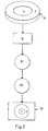
- Fig. 1 shows a flat, approximately horizontal terrain 10 and the overlying airspace 12. A portion of this air space 12, which may extend down to the terrain, forms a monitoring space 14, which is monitored by means of a sensor device 16.
- the sensor device 16 is located at a sensor location S. In the present case, the sensor device 16 is a radar sensor device.
- the monitoring space 14 is composed of a near zone N and a far zone F.
- the sensor device 16 rotates continuously about a vertical sensor axis 18. In this case it continuously monitors the monitoring space 14 in changing sectors, but in total over 360 °, in a circle with a radius s around the sensor location S and in a height range h.
- Radar sensor devices are the commonly used sensor devices, but other suitable sensor devices can be used, it is only essential that they are able to monitor said monitoring space 14 and to provide detection data that provides a sufficiently accurate display of images of the interstitial space 14 guarantee.
- the aforementioned sensor device 16 can also have a plurality of sensor units which monitor different parts of the monitoring space 14, for example different height and / or distance ranges.
- Two sensor units can either be arranged at the sensor location S, or the first sensor unit can be arranged at the sensor location S and the second sensor unit can be spaced therefrom.
- detection data D1 Due to the activity of the sensor device 16 detection data D1 are provided. This detection data D1 is converted to display data D2. On the basis of the display data D2, the images 14 * of the monitoring space 14 are displayed by means of a display device 20.
- the display device 20 may also display images based on the detection data from two sensor devices located at different sensor locations, however, coordinate transformations corresponding to at least the images 14 * based on the detection data of one of the sensor devices must be made.
- a radar sensor device is used as the sensor device 16 or a sensor device which is arranged at a fixed sensor location and in which the actual sensor element rotates continuously and at its rotation detection data of the interstitial space along 360 ° detected.
- the display device 20 can be formed by a single display unit, on which the images of the entire monitoring space 14 are displayed, ie images 14 * covering an entire height range h and an area with the radius s over 360 °, as shown in FIG Fig. 3A is shown. But it is also possible to use a display device 20 with a plurality of display units 20.1, 20.2, .... In this case, each display unit is used to display images 14.1 *, 14.2 *, ... of a specific part of the interstitial space 14. If, for example, as in Fig. 3B shown, four display units 20.1, 20.2, 20.3, 20.4 are used, then each of these four display units 20.1, 20.2, 20.3, 20.4 cover a region in the form of a sector of 90 °.
- images of different height ranges of the interstitial space 14 can also be displayed by different display units.
- the use of a display device 14 with more than one display unit is particularly useful when the states in the interstitial space 14 change frequently and / or quickly, but it practically requires that an operating / monitoring person is available per display unit.
- the images 14 * of a near zone N of the interstitial space 14 are displayed in an inner region I and with a constant scale M (I) for the entire inner region I. These images 14 * are thus all, relative to the monitoring space 14, displayed reduced in size.
- the scale M (I) used here is preferably selectable. In any case, this scale M (I) is chosen so that the display can be made with a relatively high resolution.
- the information provided by the display device 20 must be accurate enough to be utilized, for example to activate an effector 22, as described below.
- the images 14 * of the vicinity N of the interstitial space 14 in the inner area I of the display device 20 are, as mentioned, usually displayed in a circle sector and lie between the center Z of a circle from which this circle sector is cut out, and a boundary line l.
- the angle over which this circular sector extends may, for example, be 90 °. If n display units are available, each can be responsible for a circular sector with an angle of 360 ° / n. However, for certain reasons, the interstitial space 14 can also extend over an angle of only 180 °, and even then the images 14 * appear on the display device only in a circular sector which in this case includes 180 °.
- the angle over which the circular sector extends can also be 360 °, as in Fig. 3A which means that the circular sector becomes a full circle.
- images 14 * of the long range F of the interstitial space 14 are displayed, in one to the inner area I. adjacent outer area A of the display device 20, and thus in a circular ring sector.
- Circular sector and annulus usually extend over the same angular range. As already mentioned, this angular range can be up to 360 °, whereby then the circular sector to a full circle and the circular ring sector to a full circular ring.
- the display center Z of the circle and the circular ring, from which, if necessary, the circular sector and the circular ring sector are cut out, can correspond to the image of the sensor location S.
- the display center Z can also be an image of a location spaced from the sensor location S, it then being necessary to subject the data acquired by the sensor device 16 to a corresponding coordinate transformation.
- the images 14 * of the far region F of the surveillance space 14, which are displayed in the outer area A, are displayed with increasing distance to the inner area I in a progressively decreasing scale M (A). Relative to the monitoring space 14, therefore, these images 14 * are all the more reduced the farther they are from the inner area I.
- the images 14 * of the outer area A are hereby displayed in a resolution which is less fine than the resolution with which the images 14 * are displayed in the inner area I. It is not primarily the intention to immediately exploit information provided by the outdoor display A, for example, to activate the effector 22.
- the outdoor display A is to be viewed primarily as a preview or advance warning of events, which possibly take place after a short period of time in the vicinity N of the monitoring space 14 and are then displayed in the interior I.
- the progressively decreasing scale M (A), in which according to the invention the images 14 * of the outside area A are displayed, is preferably a logarithmic scale or a scale which is equal to a mathematical function which is approximately logarithmic.
- the inner area I and the outer area A have a common boundary line l, wherein the inner boundary of the outer area A at least approximately coincides with the outer boundary of the inner area I.
- the outer boundary of the outer area A lies within the sensor effective area or coincides with the outer boundary of the sensor effective area.
- the local scale M (A), in which the images 14 * are displayed in that part of the outside area A which adjoins the interior area I, must be at least approximately equal to the scale M (I) with which the images 14 * in FIG Indoors I are displayed so that a somewhat continuous transition is made possible.
- an effector location E of the effector 22 can according to Fig. 1 coincide with the sensor center S and its image may coincide with the display center Z.
- the effector location E can also be spaced apart from the sensor center S, which in turn can necessitate corresponding coordinate transformations.
- the boundary line 1 between the interior area I and the outside area A of the display may coincide with the effector range; in any case, it is not meaningful if the interior area I is more limited than the effector range. If the effector range lies within the near range I, then it can be indicated by an inserted effector boundary line w within the inner range I.
- the effector 22 is a firing unit, this is particularly beneficial as an operator can then see at a glance and without Another consideration sees whether an activation, that is, an insert, the effector 22 or the fire unit can be effective.
- a representation of the topography and / or, preferably in a temporally variable manner, for example signal-like flashing, and if necessary stylized, a representation of relevant components of the topography of the environment of the interstitial space 14 are displayed. If such an overlay also occurs in outdoor area A, it must be displayed or displayed in accordance with the locally applicable scale.
- Relevant components of the topography can be, for example, national borders, mountain ranges, bodies of water or, in the case of military use of the new method, objects which are particularly worthy of protection, such as further locations of further fire units, nuclear power plants or cultural objects.
- the effector range may be about 8 km, the radius of the near range N may be about 20 km, and the radius of the far range F about 80 km.
- the actual range of the sensor device 16 and of the effector 22 in each case taking into account the local conditions, as well as the type and quality of the display device 20 and the accuracy of the conversion of the detection data D1 in the display data D2 are decisive.
Landscapes
- Engineering & Computer Science (AREA)
- Computer Networks & Wireless Communication (AREA)
- Physics & Mathematics (AREA)
- General Physics & Mathematics (AREA)
- Radar, Positioning & Navigation (AREA)
- Remote Sensing (AREA)
- Radar Systems Or Details Thereof (AREA)
Priority Applications (1)
| Application Number | Priority Date | Filing Date | Title |
|---|---|---|---|
| PL04025486T PL1542033T3 (pl) | 2003-12-09 | 2004-10-27 | Sposób wyświetlania obrazów przestrzeni monitorowania |
Applications Claiming Priority (2)
| Application Number | Priority Date | Filing Date | Title |
|---|---|---|---|
| CH20902003 | 2003-12-09 | ||
| CH20902003 | 2003-12-09 |
Publications (2)
| Publication Number | Publication Date |
|---|---|
| EP1542033A1 EP1542033A1 (de) | 2005-06-15 |
| EP1542033B1 true EP1542033B1 (de) | 2014-03-05 |
Family
ID=34468804
Family Applications (1)
| Application Number | Title | Priority Date | Filing Date |
|---|---|---|---|
| EP04025486.4A Expired - Lifetime EP1542033B1 (de) | 2003-12-09 | 2004-10-27 | Verfahren zum Anzeigen von Bildern eines Überwachungsraumes |
Country Status (4)
| Country | Link |
|---|---|
| EP (1) | EP1542033B1 (pl) |
| DK (1) | DK1542033T3 (pl) |
| ES (1) | ES2455248T3 (pl) |
| PL (1) | PL1542033T3 (pl) |
Families Citing this family (2)
| Publication number | Priority date | Publication date | Assignee | Title |
|---|---|---|---|---|
| JP6150418B2 (ja) * | 2012-04-27 | 2017-06-21 | 古野電気株式会社 | 情報表示装置、魚群探知機及び情報表示方法 |
| CN109444827B (zh) * | 2018-10-31 | 2023-05-30 | 中国船舶工业系统工程研究院 | 一种用于雷达视频回波显示的方位插值方法 |
Family Cites Families (3)
| Publication number | Priority date | Publication date | Assignee | Title |
|---|---|---|---|---|
| JPH0266483A (ja) * | 1988-08-31 | 1990-03-06 | Nec Corp | レーダー表示方式 |
| US5337057A (en) * | 1993-07-12 | 1994-08-09 | Alliedsignal Inc. | Non-linear radar range scale display arrangement |
| US6621451B1 (en) * | 2002-08-13 | 2003-09-16 | Honeywell International Inc. | Use of texture memory for WX scan conversion |
-
2004
- 2004-10-27 ES ES04025486.4T patent/ES2455248T3/es not_active Expired - Lifetime
- 2004-10-27 DK DK04025486.4T patent/DK1542033T3/da active
- 2004-10-27 EP EP04025486.4A patent/EP1542033B1/de not_active Expired - Lifetime
- 2004-10-27 PL PL04025486T patent/PL1542033T3/pl unknown
Also Published As
| Publication number | Publication date |
|---|---|
| EP1542033A1 (de) | 2005-06-15 |
| PL1542033T3 (pl) | 2014-07-31 |
| DK1542033T3 (da) | 2014-06-02 |
| ES2455248T3 (es) | 2014-04-15 |
Similar Documents
| Publication | Publication Date | Title |
|---|---|---|
| EP2464098B1 (de) | Umfeld-Darstellungsvorrichtung sowie ein Fahrzeug mit einer derartigen Umfeld-Darstellungsvorrichtung und Verfahren zur Darstellung eines Panoramabildes | |
| EP2338085B1 (de) | Verfahren zum einstellen und zur anzeige der einstellung eines kameraobjektivs | |
| EP1761759B1 (de) | Verfahren zur steuerung einer rohrrevisionsanlage und zur auswertung der revisionsdaten | |
| DE102017114962B4 (de) | Multi-Sensor-Kamera | |
| EP3844946B1 (de) | Verfahren und anordnung zum erzeugen einer mit bildinformationen texturierten umfeldkarte eines fahrzeugs und fahrzeug umfassend eine solche anordnung | |
| EP1972896B1 (de) | Mensch-Maschinen-Interface zur Pilotenunterstützung bei Start und Landung eines Fluggerät bei verminderter Außensicht | |
| DE102014012831A1 (de) | Selbstfahrende Baumaschine und Verfahren zum Steuern einer selbstfahrenden Baumaschine | |
| EP2072318A1 (de) | Anzeigeinstrument für ein Kraftfahrzeug | |
| EP0445334A1 (de) | Verfahren zur Detektion von Intrudern | |
| DE60002717T2 (de) | Methode und gerät zur messung von eisbildung | |
| EP1542033B1 (de) | Verfahren zum Anzeigen von Bildern eines Überwachungsraumes | |
| EP3236440B1 (de) | Vorrichtung, system und verfahren zur markierungsfreien hangüberwachung und/oder bauüberwachung | |
| DE2842684C2 (de) | Einrichtung zur Erkennung und Verfolgung eines Zieles | |
| DE102009054214A1 (de) | Verfahren zum Erzeugen einer Darstellung einer Umgebung | |
| WO2013037971A1 (de) | Vermessungsgerät und verfahren zum gefilterten darstellen von objekt-information | |
| DE102007019808A1 (de) | Landehilfesystem für senkrecht startende und landende Luftfahrzeuge, insbesondere Helikopter | |
| EP1912431A2 (de) | Verfahren und Vorrichtung zur Steuerung einer schwenkbaren Kamera | |
| DE60037447T2 (de) | Verfahren und vorrichtung zur darstellung von gegenständen in einem umgebenden raum | |
| EP1434184B1 (de) | Steuerung eines Multikamera-Systems | |
| DE202005013989U1 (de) | Vorrichtung zur bildgestützten Umgebungserfassung bei Fahrzeugen | |
| AT527238B1 (de) | Messvorrichtung, System und Verfahren zum Überwachen eines landwirtschaftlich nutzbaren Bodenbereichs | |
| AT527033B1 (de) | Verfahren zur Darstellung und Aktualisierung eines Panoramabildes einer Landschaft | |
| AT523547B1 (de) | Anordnung zur Erstellung eines Modells einer Szene | |
| DE102013011927B4 (de) | Verfahren zum Steuern einer Überwachungseinrichtung | |
| DE1960075C3 (pl) |
Legal Events
| Date | Code | Title | Description |
|---|---|---|---|
| PUAI | Public reference made under article 153(3) epc to a published international application that has entered the european phase |
Free format text: ORIGINAL CODE: 0009012 |
|
| AK | Designated contracting states |
Kind code of ref document: A1 Designated state(s): AT BE BG CH CY CZ DE DK EE ES FI FR GB GR HU IE IT LI LU MC NL PL PT RO SE SI SK TR |
|
| AX | Request for extension of the european patent |
Extension state: AL HR LT LV MK |
|
| 17P | Request for examination filed |
Effective date: 20051208 |
|
| AKX | Designation fees paid |
Designated state(s): AT BE BG CH CY CZ DE DK EE ES FI FR GB GR HU IE IT LI LU MC NL PL PT RO SE SI SK TR |
|
| RAP1 | Party data changed (applicant data changed or rights of an application transferred) |
Owner name: RHEINMETALL AIR DEFENCE AG |
|
| RIC1 | Information provided on ipc code assigned before grant |
Ipc: G01S 7/14 20060101ALN20130724BHEP Ipc: G01S 7/12 20060101AFI20130724BHEP |
|
| GRAP | Despatch of communication of intention to grant a patent |
Free format text: ORIGINAL CODE: EPIDOSNIGR1 |
|
| INTG | Intention to grant announced |
Effective date: 20130913 |
|
| GRAS | Grant fee paid |
Free format text: ORIGINAL CODE: EPIDOSNIGR3 |
|
| GRAA | (expected) grant |
Free format text: ORIGINAL CODE: 0009210 |
|
| AK | Designated contracting states |
Kind code of ref document: B1 Designated state(s): AT BE BG CH CY CZ DE DK EE ES FI FR GB GR HU IE IT LI LU MC NL PL PT RO SE SI SK TR |
|
| REG | Reference to a national code |
Ref country code: GB Ref legal event code: FG4D Free format text: NOT ENGLISH |
|
| REG | Reference to a national code |
Ref country code: CH Ref legal event code: EP |
|
| REG | Reference to a national code |
Ref country code: AT Ref legal event code: REF Ref document number: 655226 Country of ref document: AT Kind code of ref document: T Effective date: 20140315 |
|
| REG | Reference to a national code |
Ref country code: IE Ref legal event code: FG4D Free format text: LANGUAGE OF EP DOCUMENT: GERMAN |
|
| REG | Reference to a national code |
Ref country code: ES Ref legal event code: FG2A Ref document number: 2455248 Country of ref document: ES Kind code of ref document: T3 Effective date: 20140415 |
|
| REG | Reference to a national code |
Ref country code: DE Ref legal event code: R096 Ref document number: 502004014538 Country of ref document: DE Effective date: 20140417 |
|
| REG | Reference to a national code |
Ref country code: RO Ref legal event code: EPE |
|
| REG | Reference to a national code |
Ref country code: SE Ref legal event code: TRGR |
|
| REG | Reference to a national code |
Ref country code: CH Ref legal event code: NV Representative=s name: WEINMANN ZIMMERLI, CH |
|
| REG | Reference to a national code |
Ref country code: NL Ref legal event code: T3 |
|
| REG | Reference to a national code |
Ref country code: DK Ref legal event code: T3 Effective date: 20140526 |
|
| REG | Reference to a national code |
Ref country code: GR Ref legal event code: EP Ref document number: 20140400749 Country of ref document: GR Effective date: 20140515 |
|
| REG | Reference to a national code |
Ref country code: PL Ref legal event code: T3 |
|
| PG25 | Lapsed in a contracting state [announced via postgrant information from national office to epo] |
Ref country code: CY Free format text: LAPSE BECAUSE OF FAILURE TO SUBMIT A TRANSLATION OF THE DESCRIPTION OR TO PAY THE FEE WITHIN THE PRESCRIBED TIME-LIMIT Effective date: 20140305 Ref country code: FI Free format text: LAPSE BECAUSE OF FAILURE TO SUBMIT A TRANSLATION OF THE DESCRIPTION OR TO PAY THE FEE WITHIN THE PRESCRIBED TIME-LIMIT Effective date: 20140305 |
|
| PG25 | Lapsed in a contracting state [announced via postgrant information from national office to epo] |
Ref country code: CZ Free format text: LAPSE BECAUSE OF FAILURE TO SUBMIT A TRANSLATION OF THE DESCRIPTION OR TO PAY THE FEE WITHIN THE PRESCRIBED TIME-LIMIT Effective date: 20140305 Ref country code: EE Free format text: LAPSE BECAUSE OF FAILURE TO SUBMIT A TRANSLATION OF THE DESCRIPTION OR TO PAY THE FEE WITHIN THE PRESCRIBED TIME-LIMIT Effective date: 20140305 Ref country code: BG Free format text: LAPSE BECAUSE OF FAILURE TO SUBMIT A TRANSLATION OF THE DESCRIPTION OR TO PAY THE FEE WITHIN THE PRESCRIBED TIME-LIMIT Effective date: 20140605 |
|
| PGFP | Annual fee paid to national office [announced via postgrant information from national office to epo] |
Ref country code: RO Payment date: 20140930 Year of fee payment: 11 |
|
| PG25 | Lapsed in a contracting state [announced via postgrant information from national office to epo] |
Ref country code: SK Free format text: LAPSE BECAUSE OF FAILURE TO SUBMIT A TRANSLATION OF THE DESCRIPTION OR TO PAY THE FEE WITHIN THE PRESCRIBED TIME-LIMIT Effective date: 20140305 |
|
| PGFP | Annual fee paid to national office [announced via postgrant information from national office to epo] |
Ref country code: PL Payment date: 20140922 Year of fee payment: 11 |
|
| REG | Reference to a national code |
Ref country code: DE Ref legal event code: R097 Ref document number: 502004014538 Country of ref document: DE |
|
| PG25 | Lapsed in a contracting state [announced via postgrant information from national office to epo] |
Ref country code: PT Free format text: LAPSE BECAUSE OF FAILURE TO SUBMIT A TRANSLATION OF THE DESCRIPTION OR TO PAY THE FEE WITHIN THE PRESCRIBED TIME-LIMIT Effective date: 20140707 |
|
| PGFP | Annual fee paid to national office [announced via postgrant information from national office to epo] |
Ref country code: DK Payment date: 20141022 Year of fee payment: 11 |
|
| PLBE | No opposition filed within time limit |
Free format text: ORIGINAL CODE: 0009261 |
|
| STAA | Information on the status of an ep patent application or granted ep patent |
Free format text: STATUS: NO OPPOSITION FILED WITHIN TIME LIMIT |
|
| PGFP | Annual fee paid to national office [announced via postgrant information from national office to epo] |
Ref country code: FR Payment date: 20141022 Year of fee payment: 11 Ref country code: SE Payment date: 20141021 Year of fee payment: 11 Ref country code: ES Payment date: 20141028 Year of fee payment: 11 Ref country code: CH Payment date: 20141021 Year of fee payment: 11 Ref country code: DE Payment date: 20141022 Year of fee payment: 11 Ref country code: GR Payment date: 20141014 Year of fee payment: 11 |
|
| 26N | No opposition filed |
Effective date: 20141208 |
|
| PGFP | Annual fee paid to national office [announced via postgrant information from national office to epo] |
Ref country code: NL Payment date: 20141021 Year of fee payment: 11 |
|
| REG | Reference to a national code |
Ref country code: DE Ref legal event code: R097 Ref document number: 502004014538 Country of ref document: DE Effective date: 20141208 |
|
| PGFP | Annual fee paid to national office [announced via postgrant information from national office to epo] |
Ref country code: IT Payment date: 20141028 Year of fee payment: 11 |
|
| PG25 | Lapsed in a contracting state [announced via postgrant information from national office to epo] |
Ref country code: LU Free format text: LAPSE BECAUSE OF FAILURE TO SUBMIT A TRANSLATION OF THE DESCRIPTION OR TO PAY THE FEE WITHIN THE PRESCRIBED TIME-LIMIT Effective date: 20141027 Ref country code: MC Free format text: LAPSE BECAUSE OF FAILURE TO SUBMIT A TRANSLATION OF THE DESCRIPTION OR TO PAY THE FEE WITHIN THE PRESCRIBED TIME-LIMIT Effective date: 20140305 Ref country code: SI Free format text: LAPSE BECAUSE OF FAILURE TO SUBMIT A TRANSLATION OF THE DESCRIPTION OR TO PAY THE FEE WITHIN THE PRESCRIBED TIME-LIMIT Effective date: 20140305 |
|
| GBPC | Gb: european patent ceased through non-payment of renewal fee |
Effective date: 20141027 |
|
| PG25 | Lapsed in a contracting state [announced via postgrant information from national office to epo] |
Ref country code: BE Free format text: LAPSE BECAUSE OF NON-PAYMENT OF DUE FEES Effective date: 20141031 |
|
| REG | Reference to a national code |
Ref country code: IE Ref legal event code: MM4A |
|
| PG25 | Lapsed in a contracting state [announced via postgrant information from national office to epo] |
Ref country code: GB Free format text: LAPSE BECAUSE OF NON-PAYMENT OF DUE FEES Effective date: 20141027 |
|
| PG25 | Lapsed in a contracting state [announced via postgrant information from national office to epo] |
Ref country code: IE Free format text: LAPSE BECAUSE OF NON-PAYMENT OF DUE FEES Effective date: 20141027 |
|
| REG | Reference to a national code |
Ref country code: AT Ref legal event code: MM01 Ref document number: 655226 Country of ref document: AT Kind code of ref document: T Effective date: 20141027 |
|
| PG25 | Lapsed in a contracting state [announced via postgrant information from national office to epo] |
Ref country code: AT Free format text: LAPSE BECAUSE OF NON-PAYMENT OF DUE FEES Effective date: 20141027 |
|
| REG | Reference to a national code |
Ref country code: DE Ref legal event code: R119 Ref document number: 502004014538 Country of ref document: DE |
|
| REG | Reference to a national code |
Ref country code: DK Ref legal event code: EBP Effective date: 20151031 |
|
| REG | Reference to a national code |
Ref country code: SE Ref legal event code: EUG Ref country code: CH Ref legal event code: PL |
|
| REG | Reference to a national code |
Ref country code: NL Ref legal event code: MM Effective date: 20151101 |
|
| REG | Reference to a national code |
Ref country code: GR Ref legal event code: ML Ref document number: 20140400749 Country of ref document: GR Effective date: 20160506 |
|
| PG25 | Lapsed in a contracting state [announced via postgrant information from national office to epo] |
Ref country code: IT Free format text: LAPSE BECAUSE OF NON-PAYMENT OF DUE FEES Effective date: 20151027 Ref country code: GR Free format text: LAPSE BECAUSE OF NON-PAYMENT OF DUE FEES Effective date: 20160506 Ref country code: LI Free format text: LAPSE BECAUSE OF NON-PAYMENT OF DUE FEES Effective date: 20151031 Ref country code: DE Free format text: LAPSE BECAUSE OF NON-PAYMENT OF DUE FEES Effective date: 20160503 Ref country code: CH Free format text: LAPSE BECAUSE OF NON-PAYMENT OF DUE FEES Effective date: 20151031 Ref country code: HU Free format text: LAPSE BECAUSE OF FAILURE TO SUBMIT A TRANSLATION OF THE DESCRIPTION OR TO PAY THE FEE WITHIN THE PRESCRIBED TIME-LIMIT; INVALID AB INITIO Effective date: 20041027 |
|
| REG | Reference to a national code |
Ref country code: FR Ref legal event code: ST Effective date: 20160630 |
|
| PG25 | Lapsed in a contracting state [announced via postgrant information from national office to epo] |
Ref country code: SE Free format text: LAPSE BECAUSE OF NON-PAYMENT OF DUE FEES Effective date: 20151028 Ref country code: RO Free format text: LAPSE BECAUSE OF NON-PAYMENT OF DUE FEES Effective date: 20151027 Ref country code: FR Free format text: LAPSE BECAUSE OF NON-PAYMENT OF DUE FEES Effective date: 20151102 Ref country code: NL Free format text: LAPSE BECAUSE OF NON-PAYMENT OF DUE FEES Effective date: 20151101 |
|
| PG25 | Lapsed in a contracting state [announced via postgrant information from national office to epo] |
Ref country code: DK Free format text: LAPSE BECAUSE OF NON-PAYMENT OF DUE FEES Effective date: 20151031 Ref country code: PL Free format text: LAPSE BECAUSE OF NON-PAYMENT OF DUE FEES Effective date: 20151027 |
|
| REG | Reference to a national code |
Ref country code: ES Ref legal event code: FD2A Effective date: 20161129 |
|
| PG25 | Lapsed in a contracting state [announced via postgrant information from national office to epo] |
Ref country code: ES Free format text: LAPSE BECAUSE OF NON-PAYMENT OF DUE FEES Effective date: 20151028 |
|
| PG25 | Lapsed in a contracting state [announced via postgrant information from national office to epo] |
Ref country code: TR Free format text: LAPSE BECAUSE OF NON-PAYMENT OF DUE FEES Effective date: 20151027 |