EP1541956A2 - Tank structure - Google Patents
Tank structure Download PDFInfo
- Publication number
- EP1541956A2 EP1541956A2 EP04292911A EP04292911A EP1541956A2 EP 1541956 A2 EP1541956 A2 EP 1541956A2 EP 04292911 A EP04292911 A EP 04292911A EP 04292911 A EP04292911 A EP 04292911A EP 1541956 A2 EP1541956 A2 EP 1541956A2
- Authority
- EP
- European Patent Office
- Prior art keywords
- tank
- portions
- slits
- tank member
- sidewall
- Prior art date
- Legal status (The legal status is an assumption and is not a legal conclusion. Google has not performed a legal analysis and makes no representation as to the accuracy of the status listed.)
- Withdrawn
Links
Images






Classifications
-
- F—MECHANICAL ENGINEERING; LIGHTING; HEATING; WEAPONS; BLASTING
- F28—HEAT EXCHANGE IN GENERAL
- F28F—DETAILS OF HEAT-EXCHANGE AND HEAT-TRANSFER APPARATUS, OF GENERAL APPLICATION
- F28F9/00—Casings; Header boxes; Auxiliary supports for elements; Auxiliary members within casings
- F28F9/02—Header boxes; End plates
- F28F9/0219—Arrangements for sealing end plates into casing or header box; Header box sub-elements
- F28F9/0224—Header boxes formed by sealing end plates into covers
-
- F—MECHANICAL ENGINEERING; LIGHTING; HEATING; WEAPONS; BLASTING
- F28—HEAT EXCHANGE IN GENERAL
- F28F—DETAILS OF HEAT-EXCHANGE AND HEAT-TRANSFER APPARATUS, OF GENERAL APPLICATION
- F28F9/00—Casings; Header boxes; Auxiliary supports for elements; Auxiliary members within casings
- F28F9/02—Header boxes; End plates
- F28F9/0202—Header boxes having their inner space divided by partitions
-
- F—MECHANICAL ENGINEERING; LIGHTING; HEATING; WEAPONS; BLASTING
- F28—HEAT EXCHANGE IN GENERAL
- F28F—DETAILS OF HEAT-EXCHANGE AND HEAT-TRANSFER APPARATUS, OF GENERAL APPLICATION
- F28F2220/00—Closure means, e.g. end caps on header boxes or plugs on conduits
-
- F—MECHANICAL ENGINEERING; LIGHTING; HEATING; WEAPONS; BLASTING
- F28—HEAT EXCHANGE IN GENERAL
- F28F—DETAILS OF HEAT-EXCHANGE AND HEAT-TRANSFER APPARATUS, OF GENERAL APPLICATION
- F28F2275/00—Fastening; Joining
- F28F2275/04—Fastening; Joining by brazing
Definitions
- Japanese Patent Application Laid-open No. Hei 11-118386 discloses a conventional tank structure of a heat exchanger of this type.
- this tank structure is composed of: a first tank member 101 with a substantially U-shaped cross section having a bottom to which a tube is attached; a second tank member 102 with a substantially U-shaped cross section to close a longitudinal opening of the first tank member 101; and end-face closing members 103 to close end-face openings that are formed on both end sides in the longitudinal direction of a cylinder formed by the first and second tank members 101 and 102.
- the end-face closing members 103 have main portions 103a capable of closing the end-face openings formed by the first and second tank members 101 and 102, and each of the main portions 103a has protruding lock portions 103b and 103b formed integrally therewith on center portions of upper and lower edges of the main portion 103a.
- the lock portions 103b and 103b are inserted in fitting holes 101c and 102c formed in bottoms of the first and second tank members 101 and 102 so as to be locked to them.
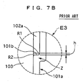
- the tank structure of the heat exchanger of this type has the following problems ascribable to the structure such that the bent portions (bent portions Z and Z with a substantially crank-shaped cross section) made of plate materials are formed in one of the tank members (sidewalls 101a and 101a) constituting coupling portions between the first and second tank members 101 and 102, and the first and second tank members 101 and 102 are assembled together with edge faces of the other tank member (sidewalls 102a and 102a) being in contact with the bent portions Z and Z.
- one of the tank members 101 and 102 is bent, for example the first tank member 101, rounded portions R1, R2 are formed in an inner corner and an outer corner of each bent portion Z of the tank member 101, respectively. Consequently, when sidewalls (102a and 102a) of the other member, for example the second tank member 102, are brought into contact with the bent portions Z and Z of the first tank member 101, corners of the other tank member 102 are in contact with and are caught by the rounded portions R1, and gaps h and h are formed between the both tank members 101 and 102. This may possibly result in poor brazing properties of these sidewall portions 101a and 102a.
- the gaps h which can not be closed by the end-face closing members 103 and 103, will be a cause of leakage from end faces. In order to avoid this leakage, it requires careful inspection of the brazing portions, resulting in a high cost.
- a tank structure comprising: a first tank member that has a substantially U-shaped cross section having a bottom portion and first and second sidewall portions connecting with both sides of the bottom portion; a second tank member that has a substantially U-shaped cross section having third and fourth sidewall portions to partially overlap with the first and second sidewall portions of the first tank member respectively and a bottom portion to close a longitudinal opening of the first tank member when the first and second tank members are assembled and fixed together with each other; and end-face closing members closing end-face openings on both end sides of the first and second tank members in a longitudinal direction of a cylinder formed by the first and second tank members, wherein the first tank member is made of plate materials and bent to be formed on the first and second sidewall portions thereof with bent portions to receive the third and fourth sidewall portions of the second tank member respectively; the first tank member having slits that are formed on the first and second sidewall portions to extend from end portions of the first and second sidewall portions toward the bottom portion through the bent portions; and said end-face closing
- the second tank member has slits to overlap at least partially with the slits of said first tank member and extend from the end portions of the third and fourth sidewall portions toward the bottom portion of the second tank member, and the lock portions are inserted in and locked by the slits of the first and second tank members.
- the slits of the first tank member are made up of fifth slits formed to extend from end portions to intermediate positions of the first and second sidewall portions through the bent portions thereof, and the slits of the second tank member is made up of sixth slits formed to extend from the end portions of the third and fourth sidewall portions toward the bottom portion of the second tank member, the six slits overlapping at least partially with the fifth slits of the first tank member when the first and second tank members are assembled with each other.
- the slits of the first tank member are made up of fifth slits formed to extend from the end portions to intermediate positions of the first and second sidewall portions of the first tank member through the bent portions thereof, and the slits of the second tank member is made up with third slits formed to extend from the end portions to intermediate positions of the third and fourth sidewall portions of the second member, the third slits overlapping partially with the fifth slits of the first tank member when the first and second tank members are assembled with each other.
- the slits of the first tank member are made up of fifth slits formed to extend from the end portions to intermediate positions of the first and second sidewall portions of the first tank member through the bent portions thereof
- the slits of the second tank member is made up of third slits formed to extend from the end portion to an intermediate position of the third sidewall portions of the second member and fourth slits formed to extend from end portions of the fourth sidewall portion to the bottom portion of the second tank member, the third and fourth slits overlapping at least partially with the fifth slits of the first tank member when the first and second tank members are assembled with each other.
- the first tank member has the slits that are formed on at least the bent portions to extend along the sidewall portions, and the lock portions integrally formed on the outer peripheries of the end-face closing members are inserted in and locked by the slits to cover the gaps between the first and second tank members. Therefore, even when the gaps are formed in the coupling portions between the first tank member and the second tank member, the lock portions of the end-face closing members block these gaps to avoid a leakage from the gaps.
- This structure can produce an effect that the end-face closing members can compensate poor brazing properties even when bent portions made of plate materials are formed in coupling portions between the first and second tank members of the tank.
- the tank structure is used for a heat exchanger of a motor vehicle.
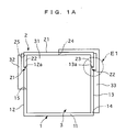
- the tank structure of the heat exchanger of the first embodiment includes: a first tank member 1 that has a substantially U-shaped cross section having sidewall portions 12 and 13 and bottom portion 11 to which a tube is attached; a second tank member 2 that has a substantially U-shaped cross section having sidewall portions 22 and 23 and a bottom portion 21 to close a longitudinal opening of the first tank member 1; and two end-face closing members 3 to close end-face openings of a cylinder formed by the first tank member 1 and the second tank member 2.
- one of the sidewall portions 12 and 13 of the first tank member 1 corresponds to a first sidewall portion of the present invention, while the other one of them corresponds to a second sidewall portion of the present invention.
- One of the sidewall portions 22 and 23 of the second tank member 2 corresponds to a third sidewall portion of the present invention, while the other one of them corresponds to a fourth sidewall portion of the present invention
- the first tank member 1 has catch steps 12a and 13a formed in edge portions of the sidewall portions 12 and 13 thereof to project outwardly, and the catch steps 12a and 13a are in contact with and catch edge portions of the sidewall portions 22 and 23 bending from the bottom portion 21 of the second member 2.
- Bent portions Z1 and Z2 bent are formed to have a substantially crank-shaped cross section from the catch steps 12a and 13a to extend along outer faces of the sidewall portions 22 and 23 of the second tank member 2, thereby covering these portions 22 and 23.
- the first tank member 1 also has first slits 14 that are formed in the sidewall portions 12 and 13 from the bottom portion 11 of the first tank member 1 to extend along the entire length of the sidewall portion 13 in a direction along the sidewall portions 12 and 13.
- the second tank member 2 has third slits 24 that partially overlap with the first slits 14 and extend along the sidewall portion 23 up to the intermediate position of the bottom portion 21.
- the first tank member 1 also has second slits 15 that are formed on the other sidewall portion 12 near the end-face openings to extend in the direction of the sidewall portions 12 and 13 from the bottom portion 11 to positions beyond at least the catch step 12a.
- the second tank member 2 has fourth slits 25 that partially overlap with the second slits 15 and extend along the entire length of the other sidewall portion 22.
- the end-face closing members 3 have main portions 31 capable of closing the end-face openings formed by the first and second tank members 1 and 2.
- the main portions 31 are integrally formed with first lock portions 33 and second lock portions 32 on outer peripheries thereof, the first lock portions 33 being inserted in and locked by the first and third slits 14 and 24, and the second lock portions 32 being inserted in and locked by the second and fourth slits 15 and 25.
- the tank of the first embodiment structured as described above is assembled by following the procedure described below.
- the first tank member 1, the second tank member 2, and the end-face closing members 3 are prepared after their formation.
- the second tank member 2 is put on the first tank member 1 to close the longitudinal opening of the first tank member 1.
- the edge faces of the sidewall portions 22 and 23 of the second tank member 2 are in contact with and are caught by the catch steps 12a and 13a of the sidewall portions 12 and 13 of the first tank member 1, as shown in FIG. 1A, FIG. 1B, and FIG. 2.
- the gaps h and h are formed at both sides between the catch steps 12a and 13a and the edges of the sidewall portions 22 and 23, where poor brazing may happen to be caused.
- This poor brazing comes from the reason that rounded portions R1 and R2 are formed in an inner corner and an outer corner of each of the bent portions Z1 and Z2 in order to form the catch steps 12a and 13a in a bent shape, and consequently, when the edge faces of the sidewall portions 22 and 23 are brought in contact with the catch steps 12a and 13a, outer corners of the edge faces are in contact with and are caught by the rounded portions R1.
- a subsequent second step will solve the problem of leakage and the like from the gaps h and h caused by poor brazing properties of these portions.
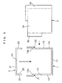
- the end-face closing members 3 are inserted from the first and third slits 14 and 24 formed in the sidewall portions 13 and 23 of the first and second tank members 1 and 2, respectively.
- the assembly is completed, and at this time, the first lock portions 33 of the end-face closing members 3 are inserted in and locked by the first and third slits 14 and 24.
- the end-face closing members 3 can compensate poor brazing properties. This can produce an effect of preventing leakage from the gaps h and h of the first and second tank members 1 and 2.
- FIGS. 4A to 6 a tank structure of a second embodiment according to the present invention will be described with the accompanying drawings of FIGS. 4A to 6.
- the same reference numerals or symbols are used to designate the same components as those in the first embodiment, and only what are different will be described.
- a first tank member 1 has fifth slits 16 and 17 that are formed on sidewall portions 13 and 12 thereof and extend from positions of the sidewall portions 13 and 12 nearer to its bottom portion 11 compared to catch steps 13a and 12a in a direction along the sidewall portions 13 and 12 to reach positions beyond at least the catch steps 13a and 12a.
- Sixth slits 26 and 27 continuing from the fifth slits 16 and 17 respectively are formed along the entire lengths of sidewall portions 23, 22 of the second tank members 2.
- End face closing members 3 have main portions 21 capable of closing end openings formed by the first tank member 1 and the second tank member 2.
- the main portions 21 is integrally formed with first lock portions 33 and second lock portions 32 on outer peripheries thereof, the first lock portions 33 being inserted in and locked by the fifth and sixth slits 16 and 26 and the second lock portions 32 being inserted in and locked by the fifth and sixth slits 17 and 27.
- the tank structure of the second embodiment described above is assembled by following the procedure described below.
- the second tank member 2 is put on the first tank member 1 to close the longitudinal opening of the first tank member 1.
- the first and second lock portions 33 and 32 of the end-face closing members 3 are inserted in and locked by the sixth slits 26 and 27 formed in the sidewall portions 23 and 22.
- edges of the sidewall portions 22 and 23 of the second tank member 2 are in contact with and are caught by catch steps 12a and 13a of the sidewall portions 12 and 13 of the first tank member 1.
- rounded portions R1, R2 are made of plate materials to have an inner corner and an outer corner of each of bent portions Z1 and Z2 in order to form the catch steps 12a and 13a in a bent shape, and consequently, when the edge faces of the sidewall portions 22 and 23 are brought in contact with the catch steps 12a and 13a, outer corners of the edge faces are in contact with and are caught by the rounded portions R1.
- gaps h and h are formed between the catch steps 12a and 13a and the edge faces of the sidewall portions 22 and 23 in the bent portions Z1 and Z2, where poor brazing may happen to be caused.
- a subsequent second step will solve the problem of leakage and the like from the gaps h and h caused by the poor brazing properties of these brazing portions.
- a third step in the assembly state shown in FIG. 4A and FIG. 5, the assembled structure is brazed in a heat treating furnace, so that contact portions of the members are fixedly coupled by brazing fillers.
- end portions of the fifth and sixth slits 16 and 26 and the first lock portions 33 in the bent portions Z2 and end portions of the fifth and sixth slits 17 and 27 and the second lock portions 32 in the bent portions Z1 are integrally joined by the brazing, so that the gaps h and h are completely closed.
- the end-face closing members 3 can compensate poor brazing properties. This can produce an effect of preventing leakage from the gaps h and h of the first and second tank members 1 and 2.
- the tank structure of the second embodiment can provide additional effects of more reliable sealability since the number of slits is smaller and of improved assemblability since the end-face closing members 3 and the second tank member 2 are assembled to the first tank member 1 in the same direction.
- bent portions may be formed only on the second tank member 1 instead of the first tank member 2, or both on the first and second tank members 1 and 2.
- the first and second tank members 1 and 2 are assembled and fixed by brazing, while they may be fixed by welding, or by both brazing and welding. In the latter case, the gaps between the first and second tank members 1 and 2 are preferably covered by brazing.
- tank structures are not limited for a heat exchanger of a motor vehicle. It can be used for other tank structure, such as oil tank and others.
- the slits of the first tank member may be made up of fifth slits formed to extend from the end portions to intermediate positions of the first and second sidewall portions of the first tank member through the bent portions thereof
- the slits of the second tank member may be made up with seventh slits, similar to the third slits, formed to extend from the end portions to intermediate positions of the third and fourth sidewall portions of the second member so that the seventh slits overlap partially with the fifth slits of the first tank member when the first and second tank members are assembled with each other.
- the slits of the first tank member is made up of fifth slits formed to extend from the end portions to intermediate positions of the first and second sidewall portions of the first tank member through the bent portions thereof
- the slits of the second tank member being made up of eighth slits, similar to the third slips, formed to extend from the end portion to an intermediate position of the third sidewall portions of the second member and ninth slits, similar to the fourth slits, formed to extend from end portions of the fourth sidewall portion to the bottom portion of the second tank member so that the eighth and ninth slits overlap at least partially with the fifth slits of the first tank member when the first and second tank members are assembled with each other.
Landscapes
- Engineering & Computer Science (AREA)
- Physics & Mathematics (AREA)
- Thermal Sciences (AREA)
- Mechanical Engineering (AREA)
- General Engineering & Computer Science (AREA)
- Heat-Exchange Devices With Radiators And Conduit Assemblies (AREA)
- Details Of Heat-Exchange And Heat-Transfer (AREA)
Abstract
Description
Claims (6)
- A tank structure comprising:characterized in that said first tank member (1) is made of plate materials and bent to be formed on the first and second sidewall portions (13, 12) thereof with bent portions (Z1, Z2) to receive the third and fourth sidewall portions (22, 23) of said second tank member (2) respectively;a first tank member (1) that has a substantially U-shaped cross section having a bottom portion (11) and first and second sidewall portions (12, 13) connecting with both sides of the bottom portion (11);a second tank member (2) that has a substantially U-shaped cross section having third and fourth sidewall portions (22, 23), to partially overlap with the first and second sidewall portions (13, 12) of said first tank member (1) respectively, and a bottom portion (21) to close a longitudinal opening of said first tank member (1) when said first and second tank members (1, 2) are assembled and fixed together with each other; andend-face closing members (3, 3) closing end-face openings on both end sides of said first and second tank members (1, 2) in a longitudinal direction of a cylinder formed by said first and second tank members (1, 2),
said first tank member (1) having slits (14, 15; 16, 17) that are formed on the first and second sidewall portions (12, 13, 22, 23) to extend from end portions of the first and second sidewall portions (13, 12) toward the bottom portion (11) through the bent portions (Z1, Z2); and
said end-face closing members (3, 3) having main portions (31, 31) capable of closing the end-face openings of said first and second tank members (1, 2), and the main portions (31, 31) being formed, on outer peripheries thereof, integrally with lock portions (32, 33) that are inserted in and locked by the slits (14, 15; 16, 17) of said first tank member (1) so as to contact with the bent portions (Z1, Z2) of said first tank member (1) and the third and fourth sidewall portions (22, 23) of said second tank member (2) and cover gaps (h, h) formed between the bent portions (Z1, Z2) and end portions of the third and fourth sidewall portions (22, 23). - The tank structure according to claim 1,
wherein said second tank member (2) has slits (24, 25; 26, 27) to overlap at least partially with the slits (14, 15; 16, 17) of said first tank member (1) and extend from the end portions of the third and fourth sidewall portions (22, 23) toward the bottom portion (21) of said second tank member (2), the lock portions (32, 33) being inserted in and locked by the slits (14, 15, 16, 17, 24, 25, 26, 27) of said first and second tank members (2). - The tank structure according to claim 2,
wherein the slits (14, 15) of said first tank member (1) are made up of first slits (14) formed to extend from the bottom portion (11) thereof to end portion of the first sidewall portion (13) of said first tank member (1) through the bent portion (Z2) thereof and second slits (15) formed to extend from an intermediate position to the end portion of the second sidewall portion (12) through the bent portion (Z1) thereof, and
the slits (24, 25) of said second tank member (2) being made up of third slits (24) formed to extend from the end portion of the third sidewall portion (23) thereof to an intermediate portion of the bottom portion (21) of said second tank member (2) and fourth slits (25) formed to extend from the end portion of the fourth sidewall portion (22) to the bottom portion (21) of said second tank member (2), the third and fourth slits (24, 25) overlapping at least partially with the first and second slits (14, 15) of said first tank member (1) when said first and second tank members(1, 2) are assembled with each other. - The tank structure according to claim 2,
wherein the slits (16, 17) of said first tank member (1) are made up of fifth slits (16, 17) formed to extend from end portions to intermediate positions of the first and second sidewall portions (13, 12) through the bent portions (Z1, Z2) thereof, and
the slits (26, 27) of said second tank member (2) being made up of sixth slits (26, 27) formed to extend from the end portions of the third and fourth sidewall portions (23, 22) toward the bottom portion (21) of said second tank member (2), the six slits (26, 27) overlapping at least partially with the fifth slits (16, 17) of said first tank member (1) when said first and second tank members (1, 2) are assembled with each other. - The tank structure according to claim 2,
wherein the slits (16, 17) of said first tank member (1) are made up of fifth slits (16, 17) formed to extend from the end portions to intermediate positions of the first and second sidewall portions (13, 12) of said first tank member (1) through the bent portions (Z1, Z2) thereof, and
the slits of said second tank member (2) being made up with seventh slits formed to extend from the end portions to intermediate positions of the third and fourth sidewall portions (23, 22) of said second member (2), the seventh slits overlapping partially with the fifth slits (16, 17) of said first tank member 81) when said first and second tank members (1, 2) are assembled with each other. - The tank structure according to claim 2,
wherein the slits (16, 17) of said first tank member (1) are made up of fifth slits (16, 17) formed to extend from the end portions to intermediate positions of the first and second sidewall portions (13, 12) of said first tank member (1) through the bent portions (Z1, Z2) thereof, and
the slits of said second tank member (2) being made up of eighth slits (24) formed to extend from the end portion to an intermediate position of the third sidewall portions (23) of said second member (2) and ninth slits formed to extend from end portions of the fourth sidewall portion (22) to the bottom portion (21) of said second tank member (2), the eighth and ninth slits overlapping at least partially with the fifth slits (16, 17) of said first tank member (1) when said first and second tank members (1, 2) are assembled with each other.
Applications Claiming Priority (2)
| Application Number | Priority Date | Filing Date | Title |
|---|---|---|---|
| JP2003409278A JP2005172269A (en) | 2003-12-08 | 2003-12-08 | Tank structure of heat exchanger |
| JP2003409278 | 2003-12-08 |
Publications (2)
| Publication Number | Publication Date |
|---|---|
| EP1541956A2 true EP1541956A2 (en) | 2005-06-15 |
| EP1541956A3 EP1541956A3 (en) | 2009-04-15 |
Family
ID=34510475
Family Applications (1)
| Application Number | Title | Priority Date | Filing Date |
|---|---|---|---|
| EP04292911A Withdrawn EP1541956A3 (en) | 2003-12-08 | 2004-12-08 | Tank structure |
Country Status (3)
| Country | Link |
|---|---|
| US (1) | US20050173104A1 (en) |
| EP (1) | EP1541956A3 (en) |
| JP (1) | JP2005172269A (en) |
Cited By (1)
| Publication number | Priority date | Publication date | Assignee | Title |
|---|---|---|---|---|
| EP3943866A1 (en) * | 2020-07-23 | 2022-01-26 | Valeo Systemes Thermiques | Heat exchanger |
Family Cites Families (8)
| Publication number | Priority date | Publication date | Assignee | Title |
|---|---|---|---|---|
| JP3329893B2 (en) * | 1993-07-20 | 2002-09-30 | 株式会社ゼクセルヴァレオクライメートコントロール | Heat exchanger header tank |
| US5607012A (en) * | 1995-06-12 | 1997-03-04 | General Motors Corporation | Heat exchanger |
| JP3760571B2 (en) * | 1997-06-24 | 2006-03-29 | 株式会社デンソー | Heat exchanger |
| JP3843340B2 (en) * | 1997-10-17 | 2006-11-08 | 株式会社ヴァレオサーマルシステムズ | Heat exchanger |
| US6216776B1 (en) * | 1998-02-16 | 2001-04-17 | Denso Corporation | Heat exchanger |
| JP2000304488A (en) * | 1999-04-23 | 2000-11-02 | Calsonic Kansei Corp | Aluminum alloy heat exchanger |
| US6115918A (en) * | 1999-06-08 | 2000-09-12 | Delphi Technologies, Inc. | Heat exchanger manifold separator installation method |
| JP4235940B2 (en) * | 2003-04-10 | 2009-03-11 | 株式会社ティラド | Heat exchanger manufacturing method and heat exchanger |
-
2003
- 2003-12-08 JP JP2003409278A patent/JP2005172269A/en not_active Withdrawn
-
2004
- 2004-12-07 US US11/005,487 patent/US20050173104A1/en not_active Abandoned
- 2004-12-08 EP EP04292911A patent/EP1541956A3/en not_active Withdrawn
Cited By (3)
| Publication number | Priority date | Publication date | Assignee | Title |
|---|---|---|---|---|
| EP3943866A1 (en) * | 2020-07-23 | 2022-01-26 | Valeo Systemes Thermiques | Heat exchanger |
| WO2022017739A1 (en) * | 2020-07-23 | 2022-01-27 | Valeo Systemes Thermiques | Heat exchanger |
| CN115956188A (en) * | 2020-07-23 | 2023-04-11 | 法雷奥热系统公司 | Heat exchanger |
Also Published As
| Publication number | Publication date |
|---|---|
| JP2005172269A (en) | 2005-06-30 |
| EP1541956A3 (en) | 2009-04-15 |
| US20050173104A1 (en) | 2005-08-11 |
Similar Documents
| Publication | Publication Date | Title |
|---|---|---|
| JP4152831B2 (en) | Hollow sill beam assembly and method for assembling hollow structural members with reinforcing members | |
| EP0838652B1 (en) | Heat exchanger | |
| JPH08226786A (en) | Heat exchanger and its manufacturing method | |
| JP3329893B2 (en) | Heat exchanger header tank | |
| JP4814757B2 (en) | duct | |
| JP4766787B2 (en) | Heat exchanger tank structure | |
| JP6067979B2 (en) | Wall body fixing part structure and vehicle part manufacturing method | |
| KR100521206B1 (en) | structure of oil cooler | |
| CN112781426B (en) | Heat exchange plate for plate heat exchanger and plate heat exchanger | |
| US20050173104A1 (en) | Tank structure | |
| JP2002257493A (en) | Manufacturing method of aluminum heat exchanger | |
| KR100737076B1 (en) | T-type branching joint | |
| KR910000265B1 (en) | Laminated heat exchanger | |
| JP2017096501A (en) | Wall body fixing part structure and vehicle part manufacturing method | |
| JP5225001B2 (en) | Heat exchanger | |
| EP1496330A2 (en) | Heat exchanger having header tanks | |
| JPH0624706Y2 (en) | Heat exchanger | |
| JP3934805B2 (en) | Two-passage exhaust pipe | |
| JP2007147197A (en) | Input/output port fixation structure of heat exchanger | |
| JP2001012891A (en) | Method of manufacturing tank for heat exchanger and tank | |
| JP4221188B2 (en) | Heat exchanger | |
| JP2008145021A (en) | Heat exchanger | |
| JP2006170525A (en) | Heat exchanger | |
| US7255390B2 (en) | Seperated-panel structure of vehiclebody panel | |
| JP2006349192A (en) | Aluminum radiator |
Legal Events
| Date | Code | Title | Description |
|---|---|---|---|
| PUAI | Public reference made under article 153(3) epc to a published international application that has entered the european phase |
Free format text: ORIGINAL CODE: 0009012 |
|
| AK | Designated contracting states |
Kind code of ref document: A2 Designated state(s): AT BE BG CH CY CZ DE DK EE ES FI FR GB GR HU IE IS IT LI LT LU MC NL PL PT RO SE SI SK TR |
|
| AX | Request for extension of the european patent |
Extension state: AL BA HR LV MK YU |
|
| PUAL | Search report despatched |
Free format text: ORIGINAL CODE: 0009013 |
|
| AK | Designated contracting states |
Kind code of ref document: A3 Designated state(s): AT BE BG CH CY CZ DE DK EE ES FI FR GB GR HU IE IS IT LI LT LU MC NL PL PT RO SE SI SK TR |
|
| AX | Request for extension of the european patent |
Extension state: AL BA HR LV MK YU |
|
| STAA | Information on the status of an ep patent application or granted ep patent |
Free format text: STATUS: THE APPLICATION IS DEEMED TO BE WITHDRAWN |
|
| AKX | Designation fees paid | ||
| 18D | Application deemed to be withdrawn |
Effective date: 20090701 |
|
| REG | Reference to a national code |
Ref country code: DE Ref legal event code: 8566 |