EP1541846A1 - Engine controller - Google Patents
Engine controller Download PDFInfo
- Publication number
- EP1541846A1 EP1541846A1 EP03766616A EP03766616A EP1541846A1 EP 1541846 A1 EP1541846 A1 EP 1541846A1 EP 03766616 A EP03766616 A EP 03766616A EP 03766616 A EP03766616 A EP 03766616A EP 1541846 A1 EP1541846 A1 EP 1541846A1
- Authority
- EP
- European Patent Office
- Prior art keywords
- crank
- crankshaft
- detecting
- intake air
- detected
- Prior art date
- Legal status (The legal status is an assumption and is not a legal conclusion. Google has not performed a legal analysis and makes no representation as to the accuracy of the status listed.)
- Withdrawn
Links
Images






Classifications
-
- F—MECHANICAL ENGINEERING; LIGHTING; HEATING; WEAPONS; BLASTING
- F02—COMBUSTION ENGINES; HOT-GAS OR COMBUSTION-PRODUCT ENGINE PLANTS
- F02D—CONTROLLING COMBUSTION ENGINES
- F02D41/00—Electrical control of supply of combustible mixture or its constituents
- F02D41/009—Electrical control of supply of combustible mixture or its constituents using means for generating position or synchronisation signals
-
- F—MECHANICAL ENGINEERING; LIGHTING; HEATING; WEAPONS; BLASTING
- F02—COMBUSTION ENGINES; HOT-GAS OR COMBUSTION-PRODUCT ENGINE PLANTS
- F02D—CONTROLLING COMBUSTION ENGINES
- F02D41/00—Electrical control of supply of combustible mixture or its constituents
- F02D41/22—Safety or indicating devices for abnormal conditions
- F02D41/222—Safety or indicating devices for abnormal conditions relating to the failure of sensors or parameter detection devices
-
- F—MECHANICAL ENGINEERING; LIGHTING; HEATING; WEAPONS; BLASTING
- F02—COMBUSTION ENGINES; HOT-GAS OR COMBUSTION-PRODUCT ENGINE PLANTS
- F02D—CONTROLLING COMBUSTION ENGINES
- F02D2200/00—Input parameters for engine control
- F02D2200/02—Input parameters for engine control the parameters being related to the engine
- F02D2200/04—Engine intake system parameters
- F02D2200/0402—Engine intake system parameters the parameter being determined by using a model of the engine intake or its components
-
- F—MECHANICAL ENGINEERING; LIGHTING; HEATING; WEAPONS; BLASTING
- F02—COMBUSTION ENGINES; HOT-GAS OR COMBUSTION-PRODUCT ENGINE PLANTS
- F02D—CONTROLLING COMBUSTION ENGINES
- F02D2200/00—Input parameters for engine control
- F02D2200/02—Input parameters for engine control the parameters being related to the engine
- F02D2200/04—Engine intake system parameters
- F02D2200/0406—Intake manifold pressure
-
- F—MECHANICAL ENGINEERING; LIGHTING; HEATING; WEAPONS; BLASTING
- F02—COMBUSTION ENGINES; HOT-GAS OR COMBUSTION-PRODUCT ENGINE PLANTS
- F02D—CONTROLLING COMBUSTION ENGINES
- F02D2200/00—Input parameters for engine control
- F02D2200/02—Input parameters for engine control the parameters being related to the engine
- F02D2200/04—Engine intake system parameters
- F02D2200/0414—Air temperature
-
- F—MECHANICAL ENGINEERING; LIGHTING; HEATING; WEAPONS; BLASTING
- F02—COMBUSTION ENGINES; HOT-GAS OR COMBUSTION-PRODUCT ENGINE PLANTS
- F02D—CONTROLLING COMBUSTION ENGINES
- F02D37/00—Non-electrical conjoint control of two or more functions of engines, not otherwise provided for
- F02D37/02—Non-electrical conjoint control of two or more functions of engines, not otherwise provided for one of the functions being ignition
-
- F—MECHANICAL ENGINEERING; LIGHTING; HEATING; WEAPONS; BLASTING
- F02—COMBUSTION ENGINES; HOT-GAS OR COMBUSTION-PRODUCT ENGINE PLANTS
- F02D—CONTROLLING COMBUSTION ENGINES
- F02D41/00—Electrical control of supply of combustible mixture or its constituents
- F02D41/0097—Electrical control of supply of combustible mixture or its constituents using means for generating speed signals
-
- F—MECHANICAL ENGINEERING; LIGHTING; HEATING; WEAPONS; BLASTING
- F02—COMBUSTION ENGINES; HOT-GAS OR COMBUSTION-PRODUCT ENGINE PLANTS
- F02D—CONTROLLING COMBUSTION ENGINES
- F02D41/00—Electrical control of supply of combustible mixture or its constituents
- F02D41/02—Circuit arrangements for generating control signals
- F02D41/14—Introducing closed-loop corrections
- F02D41/1438—Introducing closed-loop corrections using means for determining characteristics of the combustion gases; Sensors therefor
- F02D41/1444—Introducing closed-loop corrections using means for determining characteristics of the combustion gases; Sensors therefor characterised by the characteristics of the combustion gases
- F02D41/1454—Introducing closed-loop corrections using means for determining characteristics of the combustion gases; Sensors therefor characterised by the characteristics of the combustion gases the characteristics being an oxygen content or concentration or the air-fuel ratio
Definitions
- This invention relates to an engine control device for controlling an engine and, more specifically to an engine control device suitable for controlling an engine provided with a fuel injection device for injecting fuel.
- JP-A-H10-227252 an engine control device adapted to detect the phase state of a crankshaft and an intake air pressure and, based on those, to detect the stroke state of a cylinder is proposed in JP-A-H10-227252.
- this prior art it is possible to detect the stroke state of a cylinder without detecting the phase of a camshaft, so that it is possible to control fuel injection timing based on the stroke state.
- the phase of a crankshaft is detected as follows.
- the crankshaft or a member which is rotated in synchronization with the crankshaft has teeth formed on an outer periphery thereof at equal intervals with an irregular interval part and crank pulses are generated by crank pulse generating means such as a magnetic sensor along with the rotational movement of the teeth.
- crank pulse generating means such as a magnetic sensor along with the rotational movement of the teeth.
- a specific rotational position of the crankshaft corresponding to the irregular interval part of the teeth is detected based on the state of the crank pulses, and the rotational angle, namely the phase, of the crankshaft can be detected based on, for example, the number of the crank pulses from the specific rotational position of the crankshaft.
- crank pulses generated by crank pulse generating means such as a magnetic sensor are obtained by binarizing a current continuously varying as a sine curve into ON-OFF signals with a prescribed value.
- the pulses become long or no OFF-part is generated, and when the sensor is too apart from the teeth, the pulses become short or no ON-part is generated.
- the present invention has been made to solve the above problems and it is, therefore, an object of the present invention to provide an engine control device which can reliably detect an abnormal condition of crank pulse generating means.
- the engine control device according to Claim 1 of the present invention comprises:
- the engine control device comprises:
- the engine control device comprises:
- FIG. 1 is a schematic diagram illustrating an example of an engine for a motorcycle or the like and a control device therefor.
- Designated as 1 is a four-cylinder, four-stroke engine.
- the engine 1 has a cylinder body 2, a crankshaft 3, a piston 4, a combustion chamber 5, an intake pipe 6, an intake valve 7, an exhaust pipe 8, an exhaust valve 9, a spark plug 10, and an ignition coil 11.
- a throttle valve 12 which is opened and closed in accordance with accelerator opening is provided and an injector 13 as a fuel injection device is disposed downstream of the throttle valve 12.
- the injector 13 is connected to a filter 18, a fuel pump 17 and a pressure control valve 16 which are housed in a fuel tank 19.
- the engine 1 employs an independent suction system, so that the injector 13 is provided in each intake pipe 6 of each cylinder.
- the operating condition of the engine 1 is controlled by an engine control unit 15.
- a crank angle sensor 20 as crank pulse generating means for generating crank pulses for use in detecting the rotational angle, namely phase, of the crankshaft 3
- a cooling water temperature sensor 21 for detecting the temperature of the cylinder body 2 or cooling water, namely the temperature of the engine body
- an exhaust air-fuel ratio sensor 22 for detecting the air-fuel ratio in the exhaust pipe 8
- an intake air pressure sensor 24 for detecting the pressure of intake air in the intake pipe 6, and an intake air temperature sensor 25 for detecting the temperature in the intake pipe 6, namely the temperature of intake air.
- the engine control unit 15 receives detecting signals from the sensors and outputs control signals to the fuel pump 17, the pressure control valve 16, the injector 13 and the ignition coil 11.
- crank angle signals which are outputted from the crank angle sensor 20 will be described.
- a plurality of teeth 23 are formed on an outer periphery of the crankshaft 3 at generally equal intervals as shown in FIG. 2a.
- the crank angle sensor 20, such as a magnetic sensor detects the approach of the teeth 23, and the resulting current is electrically processed, namely binarized with a prescribed value, and outputted as pulse signals.
- the circumferential pitch between two adjacent teeth 23 is 30° in the phase (rotational angle) of the crankshaft 3, and the circumferential width of each of the teeth 23 is 10° in the phase (rotational angle) of the crankshaft 3.
- teeth missing part There is a part where two adjacent teeth are arranged not at the above pitch but at a pitch which is twice as large as the others. It is a special part where there is no tooth where there should be one as shown by double-dot-dash lines in FIG. 2a. This part corresponds to the irregular interval part, namely the specific rotational position. This part may be hereinafter also referred to as "tooth missing part".
- FIG. 2a shows the state where the cylinder is at compression top dead center (the state is the same when the cylinder is at exhaust top dead center).
- the pulse signal output immediately before the cylinder reaches compression top dead center is numbered as “0”, and the following pulse signals are numbered as "1", "2", "3” and "4".
- the tooth missing part which comes after the tooth 23 corresponding to the pulse signal "4", is counted as one tooth as if there were one there, and the pulse signal corresponding to the next tooth 23 is numbered as "6". When this process is continued, the tooth missing part comes again after a pulse signal "16".
- the tooth missing part is again counted as one tooth as above, and the pulse signal corresponding to the next tooth 23 is numbered as "18".
- the crankshaft 3 rotates twice, the four strokes of one cycle complete, so that the pulse signal corresponding to the next tooth 23 which appears after the pulse signal "23" is numbered as "0" again.
- the cylinder reaches compression top dead center immediately after the pulse signals numbered as "0" appear.
- the thus detected pulse signal train or each pulse signal is defined as "crank pulse”.
- crank timing can be detected.
- the teeth 23 may be formed on an outer periphery of a member which is rotated in synchronization with the crankshaft 3.
- the engine control unit 15 is constituted of a microcomputer (not shown) and so on.
- FIG. 3 is a block diagram illustrating an embodiment of the engine control operation performed by the microcomputer in the engine control unit 15.
- the engine control operation is performed by an engine rotational speed calculating part 26 for calculating the engine rotational speed based on a crank angle signal, a crank timing detecting part 27 for detecting crank timing information, namely the stroke state, based on the crank angle signal and an intake air pressure signal, an intake air amount calculating part 28 for calculating the amount of intake air based on the crank timing information detected by the crank timing detecting part 27 together with an intake air temperature signal and the intake air pressure signal, a fuel injection amount setting part 29 for setting a target air-fuel ratio based on the engine rotational speed calculated in the engine rotational speed calculating part 26 and the intake air amount calculated in the intake air amount calculating part 28 and detecting an accelerating state to calculate and set a fuel injection amount and fuel injection timing, an injection pulse output part 30 for outputting injection pulses corresponding to
- the engine rotational speed calculating part 26 calculates the rotational speed of the crankshaft as an output shaft of the engine as the engine rotational speed based on the rate of change of the crank angle signal with time. More specifically, the engine rotational speed calculating part 26 calculates an instantaneous value of the engine rotational speed by dividing the phase between two adjacent teeth 23 by time needed to detect corresponding crank pulses and an average engine rotational speed that is an average movement distance of the teeth 23.
- the crank timing detecting part 27 which has a constitution similar to the stroke judging device disclosed in JP-A-H10-227252, detects the stroke state of each cylinder as shown in FIG. 4, for example, and outputs it as crank timing information. Namely, in a four-cycle engine, the crankshaft and the camshaft are constantly rotated with a prescribed phase difference, so that when crank pulses are read as shown in FIG. 4, the fourth crank pulse after the tooth missing part, namely the crank pulse "9" or "21” represents either an exhaust stroke or a compression stroke. As is well known, during an exhaust stroke, the exhaust valve is opened and the intake valve is closed, so that the intake air pressure is high.
- the intake air pressure is low because the intake valve is still open or because of the previous intake stroke even if the intake valve is closed.
- the crank pulse "21" output when the intake air pressure is low indicates that the cylinder is on a compression stroke, and the cylinder reaches compression top dead center immediately after the crank pulse "0" is obtained.
- the present stroke state can be detected in further detail by interpolating the intervals between the pulses with the rotational speed of the crankshaft.
- the stroke state of one of the cylinders can be detected, the stroke state of the other cylinders can be judged since there are prescribed phase differences between the strokes of the cylinders.
- the intake air amount calculating part 28 comprises an intake air pressure detecting part 281 for detecting an intake air pressure based on an intake air pressure signal and crank timing information, a mass flow rate map storing part 282 in which a map for use in detecting a mass flow rate of intake air based on the intake air pressure is stored, a mass flow rate calculating part 283 for calculating a mass flow rate corresponding to the detected intake air pressure using the mass flow rate map, an intake air temperature detecting part 284 for detecting the intake air temperature of based on an intake air temperature signal, and a mass flow rate correction part 285 for correcting the mass flow rate of intake air based on the mass flow rate of intake air calculated in the mass flow rate calculating part 283 and the intake air temperature detected by the intake air temperature detecting part 284. Since the mass flow rate map is organized based on a mass flow rate at an intake air temperature of 20°C, the map is corrected with an actual intake air temperature (absolute temperature ratio) to calculate the intake air amount.
- the intake air amount is calculated using an intake air pressure measured between the moment when the cylinder reaches compression bottom dead center and the moment when the intake valve is closed.
- the intake air pressure and the pressure in the cylinder become almost the same.
- the air mass in the cylinder can be obtained from the intake air pressure, the volume in the cylinder and the intake air temperature.
- the intake air amount calculated from an intake air pressure measured before the cylinder reaches bottom dead center may differ from the air amount actually sucked into the cylinder.
- the intake air amount is calculated using an intake air pressure measured while air cannot travel between the cylinder and the intake pipe although the intake valve is open in a compression stroke.
- the effect of the partial pressure of combusted gas may be taken into consideration. Namely, since the partial pressure of combusted gas has close correlation with the engine rotational speed, the intake air amount may be subjected to correction obtained in an experiment based on the engine rotational speed.
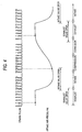
- a map, in which the mass flow rate has a relatively linear relation with the intake air pressure as shown in FIG. 6, is used as the mass flow rate map for use in calculating the intake air amount. This is because the air mass is obtained based on the Boyle-Charles law (PV nRT).
- PV Boyle-Charles law
- the fuel injection amount setting part 29 has a steady state target air-fuel ratio calculating part 33 for calculating a target air-fuel ratio in a steady state based on an engine rotational speed calculated in the engine rotational speed calculating part 26 and an intake air pressure signal, a steady state fuel injection amount calculating part 34 for calculating a fuel injection amount and fuel injection timing in the steady state based on the steady state target air-fuel ratio calculated in the steady state target air-fuel ratio calculating part 33 and the intake air amount calculated in the intake air amount calculating part 28, a fuel behavior model 35 for use in calculating a fuel injection amount and fuel injection timing in a steady state in the steady state fuel injection amount calculating part 34, accelerating state detecting means 41 for detecting an accelerating state based on a crank angle signal, an intake air pressure signal and crank timing information detected by the crank timing detecting part 27, and an accelerating time fuel injection amount calculating part 42 for calculating a fuel injection amount and fuel injection timing in an accelerating time based on the engine rotational speed calculated in the engine rotational speed calculating part
- the fuel behavior model 35 is substantially integrated with the steady state fuel injection amount calculating part 34. Namely, without the fuel behavior model 35, it is impossible to calculate and set a fuel injection amount and fuel injection timing accurately in this embodiment, in which fuel is injected into the intake pipe.
- the fuel behavior model 35 requires an intake air temperature signal, an engine rotational speed and a cooling water temperature signal.
- the steady state fuel injection amount calculating part 34 and the fuel behavior model 35 are constituted as shown in a block diagram in FIG. 7.
- M F-INJ be the amount of fuel injected from the injector 13 into the intake pipe 6
- X be the rate of the amount of fuel which adheres to the wall of the intake pipe 6 to the fuel injection amount M F-INJ
- the amount of fuel injected directly into the cylinder out of the fuel injection amount M F-INJ is ((1 - X) ⁇ M F-INJ )
- the amount of fuel which adheres to the intake pipe wall is (X ⁇ M F-INJ ).
- M F-BUF Letting M F-BUF be the amount of fuel which remains on the intake pipe wall and the rate of the amount of fuel which is taken away by an air flow to the fuel remaining amount M F-BUF be ⁇ , the amount of fuel which is taken away and flows into the cylinder is ( ⁇ ⁇ M F-BUF ).
- a cooling water correction coefficient K W is calculated from the cooling water temperature T W using a cooling water temperature correction coefficient table.
- the intake air amount M A-MAN is subjected to a fuel cut routine for cutting fuel when the throttle opening is 0, then is corrected with a flow-in air temperature T A to obtain an air flow-in amount M A .
- the air flow-in amount M A is multiplied by the reciprocal of the target air-fuel ratio AF 0 , then the result is multiplied by the cooling water temperature correction coefficient K W to obtain a required fuel flow-in amount M F .
- the fuel adhesion rate X is obtained from the engine rotational speed N E and the intake air pressure P A-MAN using a fuel adhesion rate map
- the taking-away rate ⁇ is obtained from the engine rotational speed N E and the intake air pressure P A-MAN using a taking-away rate map.
- a fuel remaining amount M F-BUF obtained in the previous calculation is multiplied by the taking-away rate ⁇ to obtain a fuel taken-away amount M F-TA
- a fuel direct flow-in amount M F-DIR is calculated by subtracting the fuel taken-away amount M F-TA from the required fuel flow-in amount M F .
- the fuel direct flow-in amount M F-DIR is (1 - X) times the fuel injection amount M F-INJ
- the fuel direct flow-in amount M F-DIR is divided by (1 - X) to obtain a steady state fuel injection amount M F-INJ . Since ((1 - ⁇ ) ⁇ M F-BUF ) amount of the fuel left in the intake pipe up to the last time still remains this time, the fuel remaining amount M F-BUF of this time is obtained by adding the fuel adhesion amount (X ⁇ M F-INJ ) thereto.
- the steady state fuel injection amount and fuel injection timing calculated and set by the steady state fuel injection amount calculating part 34 is based on the amount of intake air sucked during the previous cycle.
- the accelerating state detecting part 41 has an accelerating state threshold value table.
- the threshold value which is for use in detecting an accelerating state by comparing the difference between the present intake air pressure and the intake air pressure at the same crank angle in the same stroke as present, more specifically an intake or exhaust stroke, in the previous cycle with a prescribed value, varies according to the crank angle.
- the detection of an accelerating state is performed by comparing the difference between the present and previous intake air pressures with a prescribed value which varies according to the crank angle.
- the detection of an accelerating state is performed after a prescribed number of cycles have been completed since the previous accelerating state is detected.
- the accelerating time fuel injection amount calculating part 42 calculates an accelerating time fuel injection amount M F-ACC from a three-dimensional map based on the difference between the present and previous intake air pressures and the engine rotational speed N E when the accelerating state detecting part 41 detects an accelerating state.
- the accelerating fuel injection timing is when the accelerating state detecting part 41 detects an accelerating state. Namely, the accelerating time fuel injection amount M F-ACC of fuel is injected immediately after an accelerating state was detected.
- the ignition timing setting part 31 comprises a basic ignition timing calculating part 36 for calculating basic ignition timing based on an engine rotational speed calculated in the engine rotational speed calculating part 26 and a target air-fuel ratio calculated in the target air-fuel ratio calculating part 33, and an ignition timing correction part 38 for correcting the basic ignition timing calculated in the basic ignition timing calculating part 36 based on an accelerating time fuel injection amount calculated in the accelerating time fuel injection amount calculating part 42.
- the basic ignition timing calculating part 36 obtains the ignition timing when the maximum torque can be generated at the engine rotational speed and the target air-fuel ratio at present by retrieving a map as basic ignition timing.
- the basic ignition timing calculated in the basic ignition timing calculating part 36 is based on the result of the intake stroke of the previous cycle as in the case with the steady state fuel injection amount calculated in the steady state fuel injection amount calculating part 34.
- the ignition timing correction part 38 obtains the air-fuel ratio in the cylinder at the time when an accelerating time fuel injection amount calculated in the accelerating time fuel injection amount calculating part 42 will be added to the steady state fuel injection amount in response to the calculation of an accelerating time fuel injection amount in the accelerating time fuel injection amount calculating part 42.
- the ignition timing correction part 38 corrects ignition timing by setting new ignition timing using the air-fuel ratio in the cylinder, the engine rotational speed and the intake air pressure.
- the engine control device of the present invention can control the operating condition of the engine using intake air pressures and crank pulses without a cam sensor and a throttle sensor.
- the crank angle sensor 20 as crank pulse generating means constituted of a magnetic sensor or the like detects the approach of the teeth 23 as variation in current.
- the crank angle sensor 20 when the crank angle sensor 20 is close to the teeth 23, the current value becomes large, and when the crank angle sensor 20 is apart from the teeth 23, the current value becomes small.
- the crank pulses may be long or no OFF-part may be generated when the current value is large and the crank pulses may be short or no ON-part may be generated when the current value is small.
- Such a defect is caused by the orientation of the crank angle sensor and the accuracy of the teeth as well as the relative position of the crank angle sensor to the teeth.
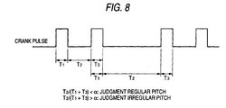
- an irregular interval part (which may be hereinafter referred to as “irregular pitch”) corresponding to the tooth missing part and a regular interval part (which may be hereinafter referred to as “regular pitch”) are detected as follows.
- a crank pulse ratio I is calculated by dividing the width T 2 of an OFF-part by the sum of the width T 1 of a crank pulse before the OFF-part and the width T 3 of a crank pulse after the OFF-part (the width T 1 to T 3 are represented by time).
- the part when the crank pulse ratio I is smaller than a prescribed value ⁇ , the part is regarded as a regular pitch and when the crank pulse ratio I is larger than a prescribed value ⁇ , the part is regarded as an irregular pitch.
- the judging method can reliably detect an irregular pitch and a regular pitch even when the rotational speed of the crankshaft, namely the engine rotational speed varies but cannot when the crank pulses are long or short as described before.
- the engine control unit 15 detects abnormality in crank pulses according to the operation shown in FIG. 9.
- the operation is performed as an interrupt process when each crank pulse falls after the input of the crank pulse, for example. Although there is provided no step for communication in this operation, information necessary for the operation is read as needed and the results of the operation are stored as needed.
- crank pulse ratio I is calculated in the step S1.
- step S2 the process goes to the step S2, where it is judged whether the crank pulse ratio I calculated in the step 1 is greater than a prescribed value ⁇ , namely whether the part is an irregular pitch.
- ⁇ a prescribed value
- the process goes to the step S3. Otherwise, the process goes to the step S4.
- step S3 it is judged whether a crank pulse counter T is not at a prescribed value To. If the crank pulse counter T is not at the prescribed value To, the process goes to the step S5. Otherwise, the process goes to the step S6.
- step S5 an interval abnormality counter CNT is incremented. Then, the process goes to the step S7.
- step S7 the crank pulse counter T is cleared to "0". Then, the process goes to the step S8.
- step S8 it is judged whether the interval abnormality counter CNT is at a value which is not smaller than a prescribed value CNT 0 . If the interval abnormality counter CNT is at a value which is not smaller than the prescribed value CNT 0 , the process goes to the step S9. Otherwise, the process returns to a main program.
- step S6 the interval abnormality counter CNT is cleared to "0". Then, the process goes to the step S10.
- step S10 the crank pulse counter T is cleared to "0". Then, the process returns to the main program.
- step S4 the crank pulse counter T is incremented. Then, the process goes to the step S11.
- step S11 it is judged whether the crank pulse counter T is at a value which is not smaller than a count-up value T MAX . If the crank pulse counter T is at a value which is not smaller than the count-up value T MAX , the process goes to the step S9. Otherwise, the process goes to the step S12.
- step S12 it is judged whether a predetermined prescribed number or more of crank pulses cannot be detected within a predetermined prescribed period of time. If the prescribed number or more of crank pulses cannot be detected within the prescribed period of time, the process goes to the step S13. Otherwise the process goes to the step S14.
- step S13 a crank pulse undetectable counter K is incremented. Then, the process goes to the step S15.
- step S15 it is judged whether the crank pulse undetectable counter K is at a value which is not smaller than a count-up value K MAX . If the crank pulse undetectable counter K is at a value which is not smaller than the count-up value K MAX , the process goes to the step S9. Otherwise, the process returns to the main program.
- step S14 the crank pulse undetectable counter K is cleared to "0". Then, the process returns to the main program.
- step S9 it is determined that there is an abnormality in crank pulses and a prescribed fail safe process is performed. Then, the operation is ended.
- the fuel safe process include gradually lowering the engine torque by decreasing the frequency of ignition gradually in each cylinder, shifting the ignition in each cylinder to the lag side gradually, or closing the throttle quickly at first and then slowly and an indication of abnormality.
- crank pulse counter T which is incremented in response to regular pitch crank pulses, reaches the count-up value T MAX or greater, in other words, an irregular pitch is not detected for a prescribed period of time for the counter to count up to T MAX , it is judged that there is an abnormality in crank pulses and a fail safe process as described before is performed. Also, when the situation in which a prescribed number or more of clank pulses are not detected for a prescribed period of time repeatedly occurs at least the count-up value K MAX of times, it is judged that there is an abnormality in crank pulses and a fail safe process as described before is performed.
- the correct number of crank pulses between irregular pitches is "11" as shown in FIG. 10a.
- the crank angle sensor is too close to the teeth
- the number of crank pulses between irregular pitches are not "11" as shown in FIG. 10c (the crank angle sensor is too far from the teeth).
- both of the situations can be detected as an abnormality in crank pulses.
- crank pulses when a prescribed number or more of crank pulses cannot be detected for a prescribed period of time although crank pulses can be detected such as when the engine is being started with a kick starter, or such a situation repeatedly occurs at least the count-up value K MAX of times, namely, when the engine does not start to rotate, a fail safe process can be performed (even if the cause is not derived from crank pulses).
- the engine control unit may be an operation circuit instead of the microcomputer.
- the crank pulse generating means is in an abnormal condition when at least one crank pulse has been detected and a specific rotational position of the crankshaft is not detected for a prescribed period of time or longer.
- an abnormal situation in which the crank pulse generating means constituted of a magnetic sensor or the like is too close to the teeth can be reliably detected.
- the crank pulse generating means is in an abnormal condition when the number of crank pulses detected while a specific rotational position of the crankshaft is detected twice is not equal to a prescribed value.
- an abnormal situation in which the crank pulse generating means constituted of a magnetic sensor or the like is too apart from to the teeth can be reliably detected.
- crank pulse generating means is in an abnormal condition when at least one crank pulse is detected and a prescribed number or more of crank pulses are not detected for a prescribed period of time.
- an abnormal situation in which crank pulses are not properly generated when, for example, the engine is being started with a kick starter can be reliably detected.
Landscapes
- Engineering & Computer Science (AREA)
- Chemical & Material Sciences (AREA)
- Combustion & Propulsion (AREA)
- Mechanical Engineering (AREA)
- General Engineering & Computer Science (AREA)
- Combined Controls Of Internal Combustion Engines (AREA)
Abstract
To reliably detect an abnormality in crank pulses due to low
accuracy of mounting a crank angle sensor.
It is determined that there is an abnormality in crank pulses when
the situation, in which a regular pitch crank pulse counter T does
not reach a prescribed value To between irregular pitch crank pulses
(interval abnormality), repeatedly occurs at least a prescribed
value CNT0 times, when an irregular pitch is not detected for a
prescribed period of time for the crank pulse counter T to count
up to TMAX or longer, or when the situation, in which a prescribed
number or more of clank pulses are not detected for a prescribed
period of time, repeatedly occurs at least a count-up value KMAX of
times.
Description
This invention relates to an engine control device for controlling
an engine and, more specifically to an engine control device suitable
for controlling an engine provided with a fuel injection device for
injecting fuel.
With the widespread of fuel injection devices called injector in
recent years, control of fuel injection timing and fuel injection
amount, namely, the air-fuel ratio has become easy, which makes it
possible to improve engine output and fuel consumption and to clean
exhaust gas. As to the fuel injection timing, it is common that the
phase state of a camshaft, the state of an intake valve, to be exact,
is detected, and, based on the detected result, fuel is injected.
However, a cam sensor for detecting the phase state of a camshaft,
which is expensive and increases the size of a cylinder head, is
difficult to be employed in particularly motorcycles. To solve this
problem, an engine control device adapted to detect the phase state
of a crankshaft and an intake air pressure and, based on those, to
detect the stroke state of a cylinder is proposed in JP-A-H10-227252.
With this prior art, it is possible to detect the stroke state of
a cylinder without detecting the phase of a camshaft, so that it
is possible to control fuel injection timing based on the stroke
state.
For example, the phase of a crankshaft is detected as follows.
The crankshaft or a member which is rotated in synchronization with
the crankshaft has teeth formed on an outer periphery thereof at
equal intervals with an irregular interval part and crank pulses
are generated by crank pulse generating means such as a magnetic
sensor along with the rotational movement of the teeth. A specific
rotational position of the crankshaft corresponding to the irregular
interval part of the teeth is detected based on the state of the
crank pulses, and the rotational angle, namely the phase, of the
crankshaft can be detected based on, for example, the number of the
crank pulses from the specific rotational position of the crankshaft.
However, when the positional relation between the crank pulse
generating means such as a magnetic sensor and the teeth is not
appropriate, the crank pulses may not be properly generated. Crank
pulses generated by crank pulse generating means such as a magnetic
sensor are obtained by binarizing a current continuously varying
as a sine curve into ON-OFF signals with a prescribed value. Thus,
when the sensor is too close to the teeth, the pulses become long
or no OFF-part is generated, and when the sensor is too apart from
the teeth, the pulses become short or no ON-part is generated. In
addition, there is conventionally no specific method for detecting
an abnormal condition of the crank pulse generating means.
The present invention has been made to solve the above problems
and it is, therefore, an object of the present invention to provide
an engine control device which can reliably detect an abnormal
condition of crank pulse generating means.
The engine control device according to Claim 1 of the present
invention comprises:
The engine control device according to Claim 2 comprises:
The engine control device according to Claim 3 comprises:
Description will be herein after made of the embodiment of the
present invention.
FIG. 1 is a schematic diagram illustrating an example of an engine
for a motorcycle or the like and a control device therefor.
Designated as 1 is a four-cylinder, four-stroke engine. The engine
1 has a cylinder body 2, a crankshaft 3, a piston 4, a combustion
chamber 5, an intake pipe 6, an intake valve 7, an exhaust pipe 8,
an exhaust valve 9, a spark plug 10, and an ignition coil 11. In
the intake pipe 6, a throttle valve 12 which is opened and closed
in accordance with accelerator opening is provided and an injector
13 as a fuel injection device is disposed downstream of the throttle
valve 12. The injector 13 is connected to a filter 18, a fuel pump
17 and a pressure control valve 16 which are housed in a fuel tank
19. The engine 1 employs an independent suction system, so that the
injector 13 is provided in each intake pipe 6 of each cylinder.
The operating condition of the engine 1 is controlled by an engine
control unit 15. As means for performing control input into the
engine control unit 15, namely means for detecting the operating
condition of the engine 1, there are provided a crank angle sensor
20 as crank pulse generating means for generating crank pulses for
use in detecting the rotational angle, namely phase, of the
crankshaft 3, a cooling water temperature sensor 21 for detecting
the temperature of the cylinder body 2 or cooling water, namely the
temperature of the engine body, an exhaust air-fuel ratio sensor
22 for detecting the air-fuel ratio in the exhaust pipe 8, an intake
air pressure sensor 24 for detecting the pressure of intake air in
the intake pipe 6, and an intake air temperature sensor 25 for
detecting the temperature in the intake pipe 6, namely the
temperature of intake air. The engine control unit 15 receives
detecting signals from the sensors and outputs control signals to
the fuel pump 17, the pressure control valve 16, the injector 13
and the ignition coil 11.
Here, the principle of crank angle signals which are outputted
from the crank angle sensor 20 will be described. In this embodiment,
a plurality of teeth 23 are formed on an outer periphery of the
crankshaft 3 at generally equal intervals as shown in FIG. 2a. The
crank angle sensor 20, such as a magnetic sensor, detects the approach
of the teeth 23, and the resulting current is electrically processed,
namely binarized with a prescribed value, and outputted as pulse
signals. The circumferential pitch between two adjacent teeth 23
is 30° in the phase (rotational angle) of the crankshaft 3, and the
circumferential width of each of the teeth 23 is 10° in the phase
(rotational angle) of the crankshaft 3. There is a part where two
adjacent teeth are arranged not at the above pitch but at a pitch
which is twice as large as the others. It is a special part where
there is no tooth where there should be one as shown by
double-dot-dash lines in FIG. 2a. This part corresponds to the
irregular interval part, namely the specific rotational position.
This part may be hereinafter also referred to as "tooth missing part".
Thus, when the crankshaft 3 is rotating at a constant speed, the
train of pulse signals corresponding to the teeth 23 appears as shown
in FIG. 2b. FIG. 2a shows the state where the cylinder is at
compression top dead center (the state is the same when the cylinder
is at exhaust top dead center). The pulse signal output immediately
before the cylinder reaches compression top dead center is numbered
as "0", and the following pulse signals are numbered as "1", "2",
"3" and "4". The tooth missing part, which comes after the tooth
23 corresponding to the pulse signal "4", is counted as one tooth
as if there were one there, and the pulse signal corresponding to
the next tooth 23 is numbered as "6". When this process is continued,
the tooth missing part comes again after a pulse signal "16". The
tooth missing part is again counted as one tooth as above, and the
pulse signal corresponding to the next tooth 23 is numbered as "18".
When the crankshaft 3 rotates twice, the four strokes of one cycle
complete, so that the pulse signal corresponding to the next tooth
23 which appears after the pulse signal "23" is numbered as "0" again.
In principle, the cylinder reaches compression top dead center
immediately after the pulse signals numbered as "0" appear. The thus
detected pulse signal train or each pulse signal is defined as "crank
pulse". When stroke detection is performed based on the crank pulse
as described later, crank timing can be detected. The teeth 23 may
be formed on an outer periphery of a member which is rotated in
synchronization with the crankshaft 3.
The engine control unit 15 is constituted of a microcomputer (not
shown) and so on. FIG. 3 is a block diagram illustrating an
embodiment of the engine control operation performed by the
microcomputer in the engine control unit 15. The engine control
operation is performed by an engine rotational speed calculating
part 26 for calculating the engine rotational speed based on a crank
angle signal, a crank timing detecting part 27 for detecting crank
timing information, namely the stroke state, based on the crank angle
signal and an intake air pressure signal, an intake air amount
calculating part 28 for calculating the amount of intake air based
on the crank timing information detected by the crank timing
detecting part 27 together with an intake air temperature signal
and the intake air pressure signal, a fuel injection amount setting
part 29 for setting a target air-fuel ratio based on the engine
rotational speed calculated in the engine rotational speed
calculating part 26 and the intake air amount calculated in the intake
air amount calculating part 28 and detecting an accelerating state
to calculate and set a fuel injection amount and fuel injection timing,
an injection pulse output part 30 for outputting injection pulses
corresponding to the fuel injection amount and the fuel injection
timing set by the fuel injection amount setting part 29 to the
injector 13 based on the crank timing information detected by the
crank timing detecting part 27, an ignition timing setting part 31
for setting ignition timing based on the crank timing information
detected by the crank timing detecting part 27 together with
the engine rotational speed calculated in the engine rotational speed
calculating part 26 and the fuel injection amount set by the fuel
injection amount setting part 29, and an ignition pulse output part
32 for outputting ignition pulses corresponding to the ignition
timing set by the ignition timing setting part 31 to the ignition
coil 11 based on the crank timing information detected by the crank
timing information detecting part 27.
The engine rotational speed calculating part 26 calculates the
rotational speed of the crankshaft as an output shaft of the engine
as the engine rotational speed based on the rate of change of the
crank angle signal with time. More specifically, the engine
rotational speed calculating part 26 calculates an instantaneous
value of the engine rotational speed by dividing the phase between
two adjacent teeth 23 by time needed to detect corresponding crank
pulses and an average engine rotational speed that is an average
movement distance of the teeth 23.
The crank timing detecting part 27, which has a constitution
similar to the stroke judging device disclosed in JP-A-H10-227252,
detects the stroke state of each cylinder as shown in FIG. 4, for
example, and outputs it as crank timing information. Namely, in a
four-cycle engine, the crankshaft and the camshaft are constantly
rotated with a prescribed phase difference, so that when crank pulses
are read as shown in FIG. 4, the fourth crank pulse after the tooth
missing part, namely the crank pulse "9" or "21" represents either
an exhaust stroke or a compression stroke. As is well known, during
an exhaust stroke, the exhaust valve is opened and the intake valve
is closed, so that the intake air pressure is high. However, in an
early stage of a compression stroke, the intake air pressure is low
because the intake valve is still open or because of the previous
intake stroke even if the intake valve is closed. Thus, the crank
pulse "21" output when the intake air pressure is low indicates that
the cylinder is on a compression stroke, and the cylinder reaches
compression top dead center immediately after the crank pulse "0"
is obtained. When a stroke state can be detected as above, the
present stroke state can be detected in further detail by
interpolating the intervals between the pulses with the rotational
speed of the crankshaft. Also, when the stroke state of one of the
cylinders can be detected, the stroke state of the other cylinders
can be judged since there are prescribed phase differences between
the strokes of the cylinders.
As shown in FIG. 5, the intake air amount calculating part 28
comprises an intake air pressure detecting part 281 for detecting
an intake air pressure based on an intake air pressure signal and
crank timing information, a mass flow rate map storing part 282 in
which a map for use in detecting a mass flow rate of intake air based
on the intake air pressure is stored, a mass flow rate calculating
part 283 for calculating a mass flow rate corresponding to the
detected intake air pressure using the mass flow rate map, an intake
air temperature detecting part 284 for detecting the intake air
temperature of based on an intake air temperature signal, and a mass
flow rate correction part 285 for correcting the mass flow rate of
intake air based on the mass flow rate of intake air calculated in
the mass flow rate calculating part 283 and the intake air temperature
detected by the intake air temperature detecting part 284. Since
the mass flow rate map is organized based on a mass flow rate at
an intake air temperature of 20°C, the map is corrected with an actual
intake air temperature (absolute temperature ratio) to calculate
the intake air amount.
In this embodiment, the intake air amount is calculated using an
intake air pressure measured between the moment when the cylinder
reaches compression bottom dead center and the moment when the intake
valve is closed. When the intake valve is opened, the intake air
pressure and the pressure in the cylinder become almost the same.
Thus, the air mass in the cylinder can be obtained from the intake
air pressure, the volume in the cylinder and the intake air
temperature. However, since the intake valve is open for a while
after a compression stroke started and air can travel between the
cylinder and the intake pipe during that time, the intake air amount
calculated from an intake air pressure measured before the cylinder
reaches bottom dead center may differ from the air amount actually
sucked into the cylinder. Thus, the intake air amount is calculated
using an intake air pressure measured while air cannot travel between
the cylinder and the intake pipe although the intake valve is open
in a compression stroke. For further accuracy, the effect of the
partial pressure of combusted gas may be taken into consideration.
Namely, since the partial pressure of combusted gas has close
correlation with the engine rotational speed, the intake air amount
may be subjected to correction obtained in an experiment based on
the engine rotational speed.
In this embodiment employing an independent suction system, a map,
in which the mass flow rate has a relatively linear relation with
the intake air pressure as shown in FIG. 6, is used as the mass flow
rate map for use in calculating the intake air amount. This is
because the air mass is obtained based on the Boyle-Charles law (PV
= nRT). When the intake pipes of the cylinders are connected, a map
shown by a broken line in FIG. 6 must be used since the premise "intake
air pressure ≒ pressure in the cylinder" does not hold because of
the effect of the pressures in the other cylinders.
The fuel injection amount setting part 29 has a steady state target
air-fuel ratio calculating part 33 for calculating a target air-fuel
ratio in a steady state based on an engine rotational speed calculated
in the engine rotational speed calculating part 26 and an intake
air pressure signal, a steady state fuel injection amount calculating
part 34 for calculating a fuel injection amount and fuel injection
timing in the steady state based on the steady state target air-fuel
ratio calculated in the steady state target air-fuel ratio
calculating part 33 and the intake air amount calculated in the intake
air amount calculating part 28, a fuel behavior model 35 for use
in calculating a fuel injection amount and fuel injection timing
in a steady state in the steady state fuel injection amount
calculating part 34, accelerating state detecting means 41 for
detecting an accelerating state based on a crank angle signal, an
intake air pressure signal and crank timing information detected
by the crank timing detecting part 27, and an accelerating time fuel
injection amount calculating part 42 for calculating a fuel injection
amount and fuel injection timing in an accelerating time based on
the engine rotational speed calculated in the engine rotational speed
calculating part 26 in response to detection of an accelerating state
by the accelerating state detecting means 41. The fuel behavior
model 35 is substantially integrated with the steady state fuel
injection amount calculating part 34. Namely, without the fuel
behavior model 35, it is impossible to calculate and set a fuel
injection amount and fuel injection timing accurately in this
embodiment, in which fuel is injected into the intake pipe. The fuel
behavior model 35 requires an intake air temperature signal, an
engine rotational speed and a cooling water temperature signal.
The steady state fuel injection amount calculating part 34 and
the fuel behavior model 35 are constituted as shown in a block diagram
in FIG. 7. Letting MF-INJ be the amount of fuel injected from the
injector 13 into the intake pipe 6 and X be the rate of the amount
of fuel which adheres to the wall of the intake pipe 6 to the fuel
injection amount MF-INJ, the amount of fuel injected directly into
the cylinder out of the fuel injection amount MF-INJ is ((1 - X) ×
MF-INJ) and the amount of fuel which adheres to the intake pipe wall
is (X × MF-INJ). Some of the fuel which adheres to the intake pipe
wall flows along the intake pipe wall into the cylinder. Letting
MF-BUF be the amount of fuel which remains on the intake pipe wall
and the rate of the amount of fuel which is taken away by an air
flow to the fuel remaining amount MF-BUF be τ, the amount of fuel which
is taken away and flows into the cylinder is (τ × MF-BUF).
In the steady state fuel injection amount calculating part 34,
a cooling water correction coefficient KW is calculated from the
cooling water temperature TW using a cooling water temperature
correction coefficient table. The intake air amount MA-MAN is
subjected to a fuel cut routine for cutting fuel when the throttle
opening is 0, then is corrected with a flow-in air temperature TA
to obtain an air flow-in amount MA. The air flow-in amount MA is
multiplied by the reciprocal of the target air-fuel ratio AF0, then
the result is multiplied by the cooling water temperature correction
coefficient KW to obtain a required fuel flow-in amount MF. Also,
the fuel adhesion rate X is obtained from the engine rotational speed
NE and the intake air pressure PA-MAN using a fuel adhesion rate map,
and the taking-away rate τ is obtained from the engine rotational
speed NE and the intake air pressure PA-MAN using a taking-away rate
map. Then, a fuel remaining amount MF-BUF obtained in the previous
calculation is multiplied by the taking-away rate τ to obtain a fuel
taken-away amount MF-TA, and a fuel direct flow-in amount MF-DIR is
calculated by subtracting the fuel taken-away amount MF-TA from the
required fuel flow-in amount MF. As described before, since the fuel
direct flow-in amount MF-DIR is (1 - X) times the fuel injection amount
MF-INJ, the fuel direct flow-in amount MF-DIR is divided by (1 - X)
to obtain a steady state fuel injection amount MF-INJ. Since ((1 -
τ) × MF-BUF) amount of the fuel left in the intake pipe up to the last
time still remains this time, the fuel remaining amount MF-BUF of this
time is obtained by adding the fuel adhesion amount (X × MF-INJ)
thereto.
Since the intake air amount calculated in the intake air amount
calculating part 28 has been detected in the final stage of the intake
stroke or the early stage of the following compression stroke of
the previous cycle prior to the present cycle, in which an explosion
(expansion) stroke is about to start, the steady state fuel injection
amount and fuel injection timing calculated and set by the steady
state fuel injection amount calculating part 34 is based on the amount
of intake air sucked during the previous cycle.
The accelerating state detecting part 41 has an accelerating state
threshold value table. The threshold value, which is for use in
detecting an accelerating state by comparing the difference between
the present intake air pressure and the intake air pressure at the
same crank angle in the same stroke as present, more specifically
an intake or exhaust stroke, in the previous cycle with a prescribed
value, varies according to the crank angle. Thus, the detection of
an accelerating state is performed by comparing the difference
between the present and previous intake air pressures with a
prescribed value which varies according to the crank angle. The
detection of an accelerating state is performed after a prescribed
number of cycles have been completed since the previous accelerating
state is detected.
The accelerating time fuel injection amount calculating part 42
calculates an accelerating time fuel injection amount MF-ACC from a
three-dimensional map based on the difference between the present
and previous intake air pressures and the engine rotational speed
NE when the accelerating state detecting part 41 detects an
accelerating state. In this embodiment, the accelerating fuel
injection timing is when the accelerating state detecting part 41
detects an accelerating state. Namely, the accelerating time fuel
injection amount MF-ACC of fuel is injected immediately after an
accelerating state was
detected.
detected.
The ignition timing setting part 31 comprises a basic ignition
timing calculating part 36 for calculating basic ignition timing
based on an engine rotational speed calculated in the engine
rotational speed calculating part 26 and a target air-fuel ratio
calculated in the target air-fuel ratio calculating part 33, and
an ignition timing correction part 38 for correcting the basic
ignition timing calculated in the basic ignition timing calculating
part 36 based on an accelerating time fuel injection amount
calculated in the accelerating time fuel injection amount
calculating part 42.
The basic ignition timing calculating part 36 obtains the ignition
timing when the maximum torque can be generated at the engine
rotational speed and the target air-fuel ratio at present by
retrieving a map as basic ignition timing. The basic ignition timing
calculated in the basic ignition timing calculating part 36 is based
on the result of the intake stroke of the previous cycle as in the
case with the steady state fuel injection amount calculated in the
steady state fuel injection amount calculating part 34. The
ignition timing correction part 38 obtains the air-fuel ratio in
the cylinder at the time when an accelerating time fuel injection
amount calculated in the accelerating time fuel injection amount
calculating part 42 will be added to the steady state fuel injection
amount in response to the calculation of an accelerating time fuel
injection amount in the accelerating time fuel injection amount
calculating part 42. Then, when the air-fuel ratio in the cylinder
largely differs from the target air-fuel ratio calculated in the
steady state target air-fuel ratio calculating part 33, the ignition
timing correction part 38 corrects ignition timing by setting new
ignition timing using the air-fuel ratio in the cylinder, the engine
rotational speed and the intake air pressure.
As described above, the engine control device of the present
invention can control the operating condition of the engine using
intake air pressures and crank pulses without a cam sensor and a
throttle sensor. The crank angle sensor 20 as crank pulse generating
means constituted of a magnetic sensor or the like detects the
approach of the teeth 23 as variation in current. Thus, when the
crank angle sensor 20 is close to the teeth 23, the current value
becomes large, and when the crank angle sensor 20 is apart from the
teeth 23, the current value becomes small. When the current value
is binarized with a prescribed value, the crank pulses may be long
or no OFF-part may be generated when the current value is large and
the crank pulses may be short or no ON-part may be generated when
the current value is small. Such a defect is caused by the
orientation of the crank angle sensor and the accuracy of the teeth
as well as the relative position of the crank angle sensor to the
teeth.
In this embodiment, an irregular interval part (which may be
hereinafter referred to as "irregular pitch") corresponding to the
tooth missing part and a regular interval part (which may be
hereinafter referred to as "regular pitch") are detected as follows.
As shown in FIG. 8, a crank pulse ratio I is calculated by dividing
the width T2 of an OFF-part by the sum of the width T1 of a crank
pulse before the OFF-part and the width T3 of a crank pulse after
the OFF-part (the width T1 to T3 are represented by time). Then,
when the crank pulse ratio I is smaller than a prescribed value α,
the part is regarded as a regular pitch and when the crank pulse
ratio I is larger than a prescribed value α, the part is regarded
as an irregular pitch. The judging method can reliably detect an
irregular pitch and a regular pitch even when the rotational speed
of the crankshaft, namely the engine rotational speed varies but
cannot when the crank pulses are long or short as described before.
Thus, the engine control unit 15 detects abnormality in crank
pulses according to the operation shown in FIG. 9. The operation
is performed as an interrupt process when each crank pulse falls
after the input of the crank pulse, for example. Although there is
provided no step for communication in this operation, information
necessary for the operation is read as needed and the results of
the operation are stored as needed.
At first in this operation, a crank pulse ratio I is calculated
in the step S1.
Then, the process goes to the step S2, where it is judged whether
the crank pulse ratio I calculated in the step 1 is greater than
a prescribed value α, namely whether the part is an irregular pitch.
When it is the tooth missing part, the process goes to the step S3.
Otherwise, the process goes to the step S4.
In the step S3, it is judged whether a crank pulse counter T is
not at a prescribed value To. If the crank pulse counter T is not
at the prescribed value To, the process goes to the step S5.
Otherwise, the process goes to the step S6.
In the step S5, an interval abnormality counter CNT is incremented.
Then, the process goes to the step S7.
In the step S7, the crank pulse counter T is cleared to "0". Then,
the process goes to the step S8.
In the step S8, it is judged whether the interval abnormality
counter CNT is at a value which is not smaller than a prescribed
value CNT0. If the interval abnormality counter CNT is at a value
which is not smaller than the prescribed value CNT0, the process goes
to the step S9. Otherwise, the process returns to a main program.
In step S6, the interval abnormality counter CNT is cleared to
"0". Then, the process goes to the step S10.
In the step S10, the crank pulse counter T is cleared to "0". Then,
the process returns to the main program.
In the step S4, the crank pulse counter T is incremented. Then,
the process goes to the step S11.
In the step S11, it is judged whether the crank pulse counter T
is at a value which is not smaller than a count-up value TMAX. If
the crank pulse counter T is at a value which is not smaller than
the count-up value TMAX, the process goes to the step S9. Otherwise,
the process goes to the step S12.
In the step S12, it is judged whether a predetermined prescribed
number or more of crank pulses cannot be detected within a
predetermined prescribed period of time. If the prescribed number
or more of crank pulses cannot be detected within the prescribed
period of time, the process goes to the step S13. Otherwise the
process goes to the step S14.
In the step S13, a crank pulse undetectable counter K is
incremented. Then, the process goes to the step S15.
In the step S15, it is judged whether the crank pulse undetectable
counter K is at a value which is not smaller than a count-up value
KMAX. If the crank pulse undetectable counter K is at a value which
is not smaller than the count-up value KMAX, the process goes to the
step S9. Otherwise, the process returns to the main program.
In the step S14, the crank pulse undetectable counter K is cleared
to "0". Then, the process returns to the main program.
In the step S9, it is determined that there is an abnormality in
crank pulses and a prescribed fail safe process is performed. Then,
the operation is ended. Examples of the fuel safe process include
gradually lowering the engine torque by decreasing the frequency
of ignition gradually in each cylinder, shifting the ignition in
each cylinder to the lag side gradually, or closing the throttle
quickly at first and then slowly and an indication of abnormality.
According to the operation, when the situation in which the crank
pulse counter T, which is incremented in response to regular pitch
crank pulses, does not reach the prescribed value To before an
irregular pitch, namely a specific rotational position of the
crankshaft, is detected since a previous irregular pitch was detected
repeatedly occurs at least a prescribed value CNT0 times, it is
determined that there is an abnormality in crank pulses and a fail
safe process as described before is performed. When the crank pulse
counter T, which is incremented in response to regular pitch crank
pulses, reaches the count-up value TMAX or greater, in other words,
an irregular pitch is not detected for a prescribed period of time
for the counter to count up to TMAX, it is judged that there is an
abnormality in crank pulses and a fail safe process as described
before is performed. Also, when the situation in which a prescribed
number or more of clank pulses are not detected for a prescribed
period of time repeatedly occurs at least the count-up value KMAX
of times, it is judged that there is an abnormality in crank pulses
and a fail safe process as described before is performed.
In this embodiment, the correct number of crank pulses between
irregular pitches is "11" as shown in FIG. 10a. However, there may
occur a situation in which no irregular pitch can be detected as
shown in FIG. 10b (the crank angle sensor is too close to the teeth)
or a situation in which the number of crank pulses between irregular
pitches are not "11" as shown in FIG. 10c (the crank angle sensor
is too far from the teeth). According to the operation shown in FIG.
9, both of the situations can be detected as an abnormality in crank
pulses. In addition, when a prescribed number or more of crank pulses
cannot be detected for a prescribed period of time although crank
pulses can be detected such as when the engine is being started with
a kick starter, or such a situation repeatedly occurs at least the
count-up value KMAX of times, namely, when the engine does not start
to rotate, a fail safe process can be performed (even if the cause
is not derived from crank pulses).
In the above embodiment, description has been made of an engine
of the type in which fuel is injected into an intake pipe but the
engine control device of the present invention is applicable to an
in-cylinder injection engine, namely, direct injection engine. In
a direct injection engine, however, adhesion of fuel to the intake
pipe does not occur, so that it is not necessary to take it into
consideration and a total amount of fuel to be injected can be used
in calculation of an air-fuel ratio.
Also in the above embodiment, description has been made of a
multi-cylinder engine having four cylinders but the engine control
device of the present invention is applicable to a single-cylinder
engine.
The engine control unit may be an operation circuit instead of
the microcomputer.
As has been described above, according to the engine control device
of Claim 1 of the present invention, it is determined that the crank
pulse generating means is in an abnormal condition when at least
one crank pulse has been detected and a specific rotational position
of the crankshaft is not detected for a prescribed period of time
or longer. Thus, an abnormal situation in which the crank pulse
generating means constituted of a magnetic sensor or the like is
too close to the teeth can be reliably detected.
According to the engine control device of Claim 2 of the present
invention, it is determined that the crank pulse generating means
is in an abnormal condition when the number of crank pulses detected
while a specific rotational position of the crankshaft is detected
twice is not equal to a prescribed value. Thus, an abnormal situation
in which the crank pulse generating means constituted of a magnetic
sensor or the like is too apart from to the teeth can be reliably
detected.
As has been described above, according to the engine control device
of Claim 3 of the present invention, it is determined that the crank
pulse generating means is in an abnormal condition when at least
one crank pulse is detected and a prescribed number or more of crank
pulses are not detected for a prescribed period of time. Thus, an
abnormal situation in which crank pulses are not properly generated
when, for example, the engine is being started with a kick starter
can be reliably detected.
Claims (3)
- An engine control device comprising:crank pulse generating means for outputting pulse signals along with rotation of a crankshaft,crankshaft phase detecting means for detecting said pulse signals outputted from said crank pulse generating means as crank pulses and detecting the phase of said crankshaft by detecting a specific rotational position of said crankshaft based on said crank pulses,intake air pressure detecting means for detecting the intake air pressure in an intake pipe of an engine,engine control means for controlling the operating condition of said engine based on the phase of the crankshaft detected by said crankshaft phase detecting means and the intake air pressure detected by said intake air pressure detecting means, andcrank pulse abnormality detecting means for determining that said crank pulse generating means is in an abnormal condition when at least one crank pulse is detected by said crankshaft phase detecting means and said specific rotational position of the crankshaft is not detected for a prescribed period of time or longer.
- An engine control device comprising:crank pulse generating means for outputting pulse signals along with rotation of a crankshaft,crankshaft phase detecting means for detecting said pulse signals outputted from said crank pulse generating means as crank pulses and detecting the phase of the crankshaft by detecting a specific rotational position of the crankshaft based on the crank pulses,intake air pressure detecting means for detecting the intake air pressure in an intake pipe of an engine,engine control means for controlling the operating condition of the engine based on the phase of the crankshaft detected by said crankshaft phase detecting means and the intake air pressure detected by said intake air pressure detecting means, andcrank pulse abnormality detecting means for determining that said crank pulse generating means is in an abnormal condition when the number of crank pulses detected while said crankshaft phase detecting means detects said specific rotational position of the crankshaft twice is not equal to a prescribed value.
- An engine control device comprising:crank pulse generating means for outputting pulse signals along with rotation of a crankshaft,crankshaft phase detecting means for detecting the pulse signals outputted from said crank pulse generating means as crank pulses and detecting the phase of the crankshaft by detecting a specific rotational position of the crankshaft based on the crank pulses,intake air pressure detecting means for detecting the intake air pressure in an intake pipe of an engine,engine control means for controlling the operating condition of the engine based on the phase of the crankshaft detected by said crankshaft phase detecting means and the intake air pressure detected by said intake air pressure detecting means, andcrank pulse abnormality detecting means for determining that said crank pulse generating means is in an abnormal condition when at least one crank pulse is detected and a prescribed number or more of crank pulses are not detected for a prescribed period of time by said crankshaft phase detecting means.
Applications Claiming Priority (3)
| Application Number | Priority Date | Filing Date | Title |
|---|---|---|---|
| JP2002225159 | 2002-08-01 | ||
| JP2002225159 | 2002-08-01 | ||
| PCT/JP2003/004665 WO2004013479A1 (en) | 2002-08-01 | 2003-04-11 | Engine controller |
Publications (2)
| Publication Number | Publication Date |
|---|---|
| EP1541846A1 true EP1541846A1 (en) | 2005-06-15 |
| EP1541846A4 EP1541846A4 (en) | 2009-04-15 |
Family
ID=31492146
Family Applications (1)
| Application Number | Title | Priority Date | Filing Date |
|---|---|---|---|
| EP03766616A Withdrawn EP1541846A4 (en) | 2002-08-01 | 2003-04-11 | Engine controller |
Country Status (8)
| Country | Link |
|---|---|
| US (1) | US6990405B2 (en) |
| EP (1) | EP1541846A4 (en) |
| JP (1) | JP4073914B2 (en) |
| CN (1) | CN1671957B (en) |
| AU (1) | AU2003236228A1 (en) |
| BR (1) | BR0313152A (en) |
| TW (1) | TWI247076B (en) |
| WO (1) | WO2004013479A1 (en) |
Cited By (2)
| Publication number | Priority date | Publication date | Assignee | Title |
|---|---|---|---|---|
| WO2013102663A1 (en) * | 2012-01-05 | 2013-07-11 | Piaggio & C. S.P.A. | Combined ignition and fuel supply system for internal combustion engines |
| WO2017088971A1 (en) * | 2015-11-26 | 2017-06-01 | Continental Automotive France | Method for determining the angular position of an engine |
Families Citing this family (11)
| Publication number | Priority date | Publication date | Assignee | Title |
|---|---|---|---|---|
| CN1671957B (en) | 2002-08-01 | 2010-06-02 | 雅马哈发动机株式会社 | engine control unit |
| US7607415B2 (en) * | 2006-10-03 | 2009-10-27 | Gm Global Technology Operations, Inc. | Method of crank signal disturbance compensation |
| US7761223B2 (en) * | 2008-06-17 | 2010-07-20 | Gm Global Technology Operations, Inc. | Fuel system diagnostics by analyzing engine cylinder pressure signal and crankshaft speed signal |
| US8100000B1 (en) | 2009-03-31 | 2012-01-24 | Honda Motor Co., Ltd. | Device and method for detecting vehicle engine pulse generator plate tooth defects |
| JP4758498B2 (en) * | 2009-07-06 | 2011-08-31 | 三井造船株式会社 | Engine speed calculation device and governor control system |
| JP5010659B2 (en) * | 2009-09-25 | 2012-08-29 | 株式会社デンソー | Abnormality diagnosis device for crank angle detection system |
| JP5195738B2 (en) * | 2009-12-24 | 2013-05-15 | トヨタ自動車株式会社 | Rotation sensor abnormality determination device |
| CN102235258A (en) * | 2010-04-29 | 2011-11-09 | 光阳工业股份有限公司 | Stroke judging method of double-cylinder injection engine |
| US20180195455A1 (en) * | 2017-01-12 | 2018-07-12 | GM Global Technology Operations LLC | Engine combustion phasing control during transient state |
| KR102383262B1 (en) * | 2017-11-03 | 2022-04-06 | 현대자동차주식회사 | Method for Compensating Noise of Crank Sensor |
| DE102019203376B4 (en) * | 2019-03-13 | 2021-01-21 | Vitesco Technologies GmbH | Method and device for recognizing a performance-changing manipulation of an internal combustion engine |
Family Cites Families (8)
| Publication number | Priority date | Publication date | Assignee | Title |
|---|---|---|---|---|
| JPS61275603A (en) * | 1985-05-31 | 1986-12-05 | Honda Motor Co Ltd | Detecting method for abnormality of crank angle signal of internal-combustion engine |
| JPS6361754A (en) * | 1986-09-02 | 1988-03-17 | Toyota Motor Corp | Fail safe device for internal combustion engine |
| JP2743579B2 (en) * | 1990-11-28 | 1998-04-22 | トヨタ自動車株式会社 | Rotation signal abnormality detection device |
| GB2272973B (en) * | 1992-11-14 | 1996-04-24 | Delco Electronics Corp | Method and apparatus for controlling a vehicle engine |
| JP3381394B2 (en) * | 1994-07-14 | 2003-02-24 | 株式会社デンソー | Failure diagnosis device |
| JP3839119B2 (en) * | 1997-02-13 | 2006-11-01 | 本田技研工業株式会社 | 4-cycle engine stroke discrimination device |
| JP4096652B2 (en) * | 2002-07-30 | 2008-06-04 | 三菱ふそうトラック・バス株式会社 | Booster fuel injection system |
| CN1671957B (en) | 2002-08-01 | 2010-06-02 | 雅马哈发动机株式会社 | engine control unit |
-
2003
- 2003-04-11 CN CN038185016A patent/CN1671957B/en not_active Expired - Fee Related
- 2003-04-11 WO PCT/JP2003/004665 patent/WO2004013479A1/en not_active Ceased
- 2003-04-11 BR BR0313152-1A patent/BR0313152A/en active Search and Examination
- 2003-04-11 AU AU2003236228A patent/AU2003236228A1/en not_active Abandoned
- 2003-04-11 EP EP03766616A patent/EP1541846A4/en not_active Withdrawn
- 2003-04-11 JP JP2004525775A patent/JP4073914B2/en not_active Expired - Fee Related
- 2003-07-30 TW TW092120871A patent/TWI247076B/en not_active IP Right Cessation
-
2005
- 2005-02-01 US US11/048,633 patent/US6990405B2/en not_active Expired - Fee Related
Cited By (4)
| Publication number | Priority date | Publication date | Assignee | Title |
|---|---|---|---|---|
| WO2013102663A1 (en) * | 2012-01-05 | 2013-07-11 | Piaggio & C. S.P.A. | Combined ignition and fuel supply system for internal combustion engines |
| WO2017088971A1 (en) * | 2015-11-26 | 2017-06-01 | Continental Automotive France | Method for determining the angular position of an engine |
| FR3044361A1 (en) * | 2015-11-26 | 2017-06-02 | Continental Automotive France | METHOD FOR DETERMINING THE ANGULAR POSITION OF AN ENGINE |
| US10428752B2 (en) | 2015-11-26 | 2019-10-01 | Continental Automotive France | Method for determining the angular position of an engine |
Also Published As
| Publication number | Publication date |
|---|---|
| EP1541846A4 (en) | 2009-04-15 |
| US20050193979A1 (en) | 2005-09-08 |
| US6990405B2 (en) | 2006-01-24 |
| CN1671957A (en) | 2005-09-21 |
| CN1671957B (en) | 2010-06-02 |
| BR0313152A (en) | 2005-06-28 |
| TW200404954A (en) | 2004-04-01 |
| TWI247076B (en) | 2006-01-11 |
| JP4073914B2 (en) | 2008-04-09 |
| AU2003236228A1 (en) | 2004-02-23 |
| JPWO2004013479A1 (en) | 2006-09-21 |
| WO2004013479A1 (en) | 2004-02-12 |
Similar Documents
| Publication | Publication Date | Title |
|---|---|---|
| JP3839119B2 (en) | 4-cycle engine stroke discrimination device | |
| EP1541845B1 (en) | Engine control device | |
| US6990405B2 (en) | Engine control device | |
| US6934623B2 (en) | Engine control device | |
| JP3976322B2 (en) | Engine control device | |
| JP2003286890A (en) | Engine control device | |
| US6530360B1 (en) | Electronic control apparatus of internal combustion engine | |
| KR20130025397A (en) | Injection control method | |
| EP1452715B1 (en) | Engine controller | |
| JP2003343340A (en) | Misfire detection device for internal combustion engine | |
| JPH0783108A (en) | Combustion state detection device for internal combustion engine | |
| JP2015197074A (en) | Control device for internal combustion engine | |
| US6975934B2 (en) | Control system for correcting a torque variation of an engine | |
| US7178494B2 (en) | Variable valve timing controller for internal combustion engine | |
| CN100357583C (en) | Engine control device | |
| JP2002147269A (en) | Engine control device | |
| JP5246144B2 (en) | Intake air amount calculation device for internal combustion engine, control device for internal combustion engine | |
| EP4664089A1 (en) | Misfire detection device and misfire detection method of internal combustion engine | |
| JP4115677B2 (en) | Atmospheric pressure detection device for internal combustion engine | |
| TWI221882B (en) | Engine control device | |
| WO2004013477A1 (en) | Engine control device | |
| JP2002155844A (en) | Engine control device | |
| JP2007056767A (en) | Abnormality judgment device for fuel supply device | |
| JP2002276455A (en) | In-cylinder pressure detection device for internal combustion engine | |
| JP2013053554A (en) | Control device for internal-combustion engine |
Legal Events
| Date | Code | Title | Description |
|---|---|---|---|
| PUAI | Public reference made under article 153(3) epc to a published international application that has entered the european phase |
Free format text: ORIGINAL CODE: 0009012 |
|
| 17P | Request for examination filed |
Effective date: 20050126 |
|
| AK | Designated contracting states |
Kind code of ref document: A1 Designated state(s): AT BE BG CH CY CZ DE DK EE ES FI FR GB GR HU IE IT LI LU MC NL PT RO SE SI SK TR |
|
| AX | Request for extension of the european patent |
Extension state: AL LT LV MK |
|
| DAX | Request for extension of the european patent (deleted) | ||
| A4 | Supplementary search report drawn up and despatched |
Effective date: 20090312 |
|
| 17Q | First examination report despatched |
Effective date: 20090526 |
|
| STAA | Information on the status of an ep patent application or granted ep patent |
Free format text: STATUS: THE APPLICATION IS DEEMED TO BE WITHDRAWN |
|
| 18D | Application deemed to be withdrawn |
Effective date: 20171005 |