EP1541819A1 - Microwave regenerated diesel particulate trap - Google Patents
Microwave regenerated diesel particulate trap Download PDFInfo
- Publication number
- EP1541819A1 EP1541819A1 EP03078946A EP03078946A EP1541819A1 EP 1541819 A1 EP1541819 A1 EP 1541819A1 EP 03078946 A EP03078946 A EP 03078946A EP 03078946 A EP03078946 A EP 03078946A EP 1541819 A1 EP1541819 A1 EP 1541819A1
- Authority
- EP
- European Patent Office
- Prior art keywords
- sootfilter
- exhaust gas
- microwaves
- microwave
- microwave generator
- Prior art date
- Legal status (The legal status is an assumption and is not a legal conclusion. Google has not performed a legal analysis and makes no representation as to the accuracy of the status listed.)
- Withdrawn
Links
Images

Classifications
-
- F—MECHANICAL ENGINEERING; LIGHTING; HEATING; WEAPONS; BLASTING
- F01—MACHINES OR ENGINES IN GENERAL; ENGINE PLANTS IN GENERAL; STEAM ENGINES
- F01N—GAS-FLOW SILENCERS OR EXHAUST APPARATUS FOR MACHINES OR ENGINES IN GENERAL; GAS-FLOW SILENCERS OR EXHAUST APPARATUS FOR INTERNAL-COMBUSTION ENGINES
- F01N3/00—Exhaust or silencing apparatus having means for purifying, rendering innocuous, or otherwise treating exhaust
- F01N3/02—Exhaust or silencing apparatus having means for purifying, rendering innocuous, or otherwise treating exhaust for cooling, or for removing solid constituents of, exhaust
- F01N3/021—Exhaust or silencing apparatus having means for purifying, rendering innocuous, or otherwise treating exhaust for cooling, or for removing solid constituents of, exhaust by means of filters
- F01N3/031—Exhaust or silencing apparatus having means for purifying, rendering innocuous, or otherwise treating exhaust for cooling, or for removing solid constituents of, exhaust by means of filters having means for by-passing filters, e.g. when clogged or during cold engine start
- F01N3/032—Exhaust or silencing apparatus having means for purifying, rendering innocuous, or otherwise treating exhaust for cooling, or for removing solid constituents of, exhaust by means of filters having means for by-passing filters, e.g. when clogged or during cold engine start during filter regeneration only
-
- F—MECHANICAL ENGINEERING; LIGHTING; HEATING; WEAPONS; BLASTING
- F01—MACHINES OR ENGINES IN GENERAL; ENGINE PLANTS IN GENERAL; STEAM ENGINES
- F01N—GAS-FLOW SILENCERS OR EXHAUST APPARATUS FOR MACHINES OR ENGINES IN GENERAL; GAS-FLOW SILENCERS OR EXHAUST APPARATUS FOR INTERNAL-COMBUSTION ENGINES
- F01N3/00—Exhaust or silencing apparatus having means for purifying, rendering innocuous, or otherwise treating exhaust
- F01N3/02—Exhaust or silencing apparatus having means for purifying, rendering innocuous, or otherwise treating exhaust for cooling, or for removing solid constituents of, exhaust
- F01N3/021—Exhaust or silencing apparatus having means for purifying, rendering innocuous, or otherwise treating exhaust for cooling, or for removing solid constituents of, exhaust by means of filters
- F01N3/023—Exhaust or silencing apparatus having means for purifying, rendering innocuous, or otherwise treating exhaust for cooling, or for removing solid constituents of, exhaust by means of filters using means for regenerating the filters, e.g. by burning trapped particles
- F01N3/027—Exhaust or silencing apparatus having means for purifying, rendering innocuous, or otherwise treating exhaust for cooling, or for removing solid constituents of, exhaust by means of filters using means for regenerating the filters, e.g. by burning trapped particles using electric or magnetic heating means
- F01N3/028—Exhaust or silencing apparatus having means for purifying, rendering innocuous, or otherwise treating exhaust for cooling, or for removing solid constituents of, exhaust by means of filters using means for regenerating the filters, e.g. by burning trapped particles using electric or magnetic heating means using microwaves
-
- H—ELECTRICITY
- H05—ELECTRIC TECHNIQUES NOT OTHERWISE PROVIDED FOR
- H05B—ELECTRIC HEATING; ELECTRIC LIGHT SOURCES NOT OTHERWISE PROVIDED FOR; CIRCUIT ARRANGEMENTS FOR ELECTRIC LIGHT SOURCES, IN GENERAL
- H05B6/00—Heating by electric, magnetic or electromagnetic fields
- H05B6/64—Heating using microwaves
- H05B6/80—Apparatus for specific applications
-
- F—MECHANICAL ENGINEERING; LIGHTING; HEATING; WEAPONS; BLASTING
- F01—MACHINES OR ENGINES IN GENERAL; ENGINE PLANTS IN GENERAL; STEAM ENGINES
- F01N—GAS-FLOW SILENCERS OR EXHAUST APPARATUS FOR MACHINES OR ENGINES IN GENERAL; GAS-FLOW SILENCERS OR EXHAUST APPARATUS FOR INTERNAL-COMBUSTION ENGINES
- F01N2330/00—Structure of catalyst support or particle filter
- F01N2330/06—Ceramic, e.g. monoliths
Definitions
- the invention relates to a self-burncleaning sootfilter for a diesel engine, comprising a sootfilter element for filtering soot from an exhaust gas of the diesel engine, and a heating system arranged for increasing the temperature in at least a part of the sootfilter, said heating system comprising a microwave generator for generating microwaves.
- the invention also relates to an exhaust gas system for a diesel engine, comprising such a self-burncleaning sootfilter, to a diesel engine provided with such an exhaust gas system, as well as to a vehicle comprising such an exhaust gas system.
- the invention furthermore relates to a method for cleaning a sootfilter for a diesel engine.
- Sootfilters are used in, for example, vehicles with diesel engines to clean the exhaust gases by removing soot particles from the exhaust gases. More generally, sootfilters are used in apparatuses in which combustion takes place and soot-containing exhaust gas is released. However, in use, the sootfilter becomes saturated with soot, which affects the sootfilter operation. The saturated sootfilter has to be replaced with a new filter or the soot has to be removed from the saturated filter. Sootfilters are known in which the soot can be removed by burning the soot together with the fuel and lubrication oil remainders adhered to the soot, thereby cleaning the sootfilter. A contaminated filter can fully or almost fully be cleaned by means of such after-burning.
- sootfilters require additional means for preheating a contaminated sootfilter element prior to soot combustion.
- One category of such known sootfilters is based upon preheating of a contaminated sootfilter element by means of microwaves.
- the known microwave-based self-cleaning sootfilters comprise a filter housing and a lossy filter element therein. Microwaves generated by a microwave generator are injected into the filter element in order to heat the filter element prior to soot combustion.
- the filter housing together with the filter element constitute a microwave cavity and the lossy sootfilter element acts as an absorber for the microwaves.
- special filter elements have been developed. For instance, cordierite filter elements are known which are provided with a layer which absorbs microwave radiation.
- the known sootfilters suffer from a number of drawbacks.
- the heating of the sootfilter element is nonuniform. This may lead to incomplete filter regeneration.
- parts of the sootfilter element may melt. This frequently happens for filter elements comprising cordierite, but can also happen for silicon carbide elements.
- thermal stress induced by the microwave heating of the filter element cracks can occur in the filter element.
- Another drawback is, that high power and/or long preheating time of the microwave generator is required in order to heat the filter element. This results into a low efficiency of the filter regeneration process.
- a further drawback is, that special measures taken in order to enhance the microwave absorption by the filter element, sometimes have a negative influence upon the efficiency and reliability of sootfiltering. For example, applying microwave absorbing coatings to a filter element can lead to unwanted penetration of such coatings into the filtering pores, thereby affecting the filtering characteristics of the filter element.
- the invention seeks to achieve said goal by providing a self-burncleaning sootfilter for a diesel engine, comprising a sootfilter element for filtering soot from an exhaust gas of the diesel engine, and a heating system arranged for increasing the temperature in at least a part of the sootfilter, said heating system comprising a microwave generator for generating microwaves, wherein the sootfilter element is substantially transparent for the microwaves generated by the microwave generator and the microwave radiation can be absorbed by soot.
- the soot in a sootfilter according to the invention can undergo a substantially direct heating. That is, unlike known sootfilters, no preheating of the filter element is required prior to heating of the soot. Since preheating of the filter element normally requires more power than direct heating of the soot, an improved sootfilter is obtained with efficient self-cleaning properties.
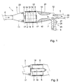
- the sootfilter 1 comprises a filter housing 3 which has an inlet 4 for providing exhaust gas to be filtered to the inside of the housing 3 and an outlet 5 for discharging filtered exhaust gas.
- a sootfilter element 2 is housed in a cilindrical part 22 of the filter housing 3, which cilindrical part 22 lies between the inlet 4 and the outlet 5.
- the filter 1 further comprises a microwave generator 6 which can inject microwave radiation into the inside of the housing 3.
- microwave radiation at least comprises electromagnetic radiation with a frequency in the range of 2400 - 2600 MHz. More particular, the microwave radiation can be injected into the sootfilter element 2, as will be explained below in more detail.
- the sootfilter element 2 is substantially transparent for microwaves generated by the microwave generator 6. Thereby, the microwave wave radiation can heat up soot present in the sootfilter element 2, without significant loss of heating energy in the sootfilter element 2.
- the sootfilter element 2 may for example be a cordierite wall-flow filter element, which is a normal commercially available element. However, any high temperature ceramic filter element can be used instead, provided the element itself presents low loss to the microwaves.
- the housing 3 has conical sections 23, 24 connected to both sides of the cilindrical part 22.
- the conical section 23 is connected to the inlet 4 and the conical section 24 is connected to the outlet 5.
- the microwave generator 6 is connected to the filter housing 3 via a waveguide 7.
- the waveguide 7 preferably is flexible. The flexibility protects the microwave generator 6 against vibrations, for example against vibrations occurring in a vehicle in which the sootfilter 1 is applied.
- the microwave generator 6 can for example be a 2450 MHz magnetron, which has a high efficiency.
- Microwave generators for 2450 MHz radiation are generally known from other fields of technology, such as microwave oven technology. These generators are produced in large amounts and are therefore available at low cost. However, other microwave generators can be applied as well.
- the microwave generator 6 is located in the exhaust gas flow downstream of the sootfilter element 2. This is advantageous compared with an upstream location, because downstream the exhaust gas is already cleaned and has smaller temperature gradients, which is favourable with respect to the life span of the microwave generator 6.
- the waveguide 7 in this example has a rectangular cross-section.
- transverse electric (“TE") microwaves that correspond to such rectangular shaped waveguide 7 are of the so-called TE01-mode type.
- the filter 1 comprises an orthomode coupler 9 which can be of a known type and which is located inside the housing 3 at the transition zone between the waveguide 7 and the housing 3.
- the orthomode coupler 9 converts the TE01-waves into TE11-waves corresponding to the circular shaped cross-section of the housing 3.
- the filter 1 further comprises a circular polarizer 10 located inside the housing 3 between the orthomode coupler 9 and the filter element 2.
- the circular polarizer 10 converts the TE11-wave into a circular polarized TE11-wave. Circular polarization is advantageous since it contributes to the uniformness of the heating of the soot in the sootfilter element 2, especially in the tangential direction of the sootfilter.
- the circular polarizer 10 in this example comprises two metallic fins 10.
- the fins may be, instead of a metal, also of a low loss dielectric material.
- the fins 10 are connected to the inner side of the filter housing 3 along which they extend in longitudinal direction.
- the two fins 10 furthermore extend radially inward with respect to the filter 1 and are located diametrically opposite with respect to one another.
- the realization of the circular polarizer 10 by means of these simple add-on fins is favourable because of ease of production.
- the sootfilter 1 comprises a microwave reflection grid 11.
- the reflection grid 11 has an adjustable position with respect to the sootfilter element 2 and is substantially disk shaped with a disk surface perpendicular to the longitudinal axis of the filter 1.
- the presence of the reflection grid 11 influences positions of antinodal planes of the microwaves, that is planes in which transverse microwaves have maximum amplitude and in which therefore maximum heating power is available. It is also possible to use other types of reflection grids or to use no reflection grid at all.
- the wall of the conical section 23 of the housing 3 can serve as reflection wall for microwaves, although this might be less preferable in some cases since a less favourable configuration of antinodal surfaces might result.
- the sootfilter 1 further comprises a tuner 12 inside the housing 3 at or nearby an axial range of the filter 1 where the waveguide 7 is connected to the housing 3.
- the tuner 12 is for impedance matching of microwaves in the sootfilter 1 to the microwave generator 6.
- a further measure to contribute to the uniformness of the heating of the soot in the sootfilter element 2 is to inactivate for sootfiltering a central section of the sootfilter element 2.
- this is achieved by partially covering each of the two axial endplanes of the sootfilter element 2 concentrically by a disk shaped blocking lid 17.
- the two identical lids 17 prevent deposit of soot in a central section 18 of the sootfilter element 2 between the two lids 17. This prevents the occurrence of too high temperatures in the central section 18 during microwave filter regeneration.
- the central section 18 can thus serve as a central cooling region during filter regeneration, which contributes to the uniformness of heating and after-burning of the soot in the sootfilter element 2.
- a sootfilter element 2 can be applied in which a core similar to the central section 18 of Figure 1 is without filter material, while exhaust gas flow through the core is prevented for instance by application of a closed pipe.
- Figure 2 shows an example of such a pipe 19 applied in a sootfilter according to the invention.
- the pipe 19 is made of a metal or a low loss dielectric material.
- the housing 3 is constructed of a full metallic enclosure. Thereby, leakage of microwave radiation is suppressed, since the enclosure reflects the radiation. Furthermore, the diameters of the inletpipe 4 and the outletpipe 5 are small enough to guarantee that the microwaves cannot propagate through theses pipes. For example with standard diameters of 5 cm or smaller, microwave leakage at 2450 MHz is effectively blocked because the pipes are below "cut-off" for the dominant TE11 mode of operation. Alternatively or additionally, the microwaves travelling towards the inlet 4 or outlet 5 can be reflected back into the inside of the housing 3 by means of reflection grids, for instance a reflection grid at the transition to the outlet 5. Moreover, the waveguide 7 and the microwave generator 6 can be integral parts of the sootfilter 1, which also contributes to the suppression of microwave leakage.
- the sootfilter 1 comprises means for estimating the degree of sootloading. With such means it can be determined when the sootfilter needs regeneration. For conventional sootfilters often use is made of pressure drop measurements over the filter elements in order to estimate sootloading. This type of sootloading estimation can also be applied for the sootfilter according to the invention. However, it is remarked that for a sootfilter according to the invention also microwave technology can be applied for estimating the amount of soot contained in the sootfilter element. Thereto a microwave generator, for example the microwave generator 6, in combination with a known standing wave detector located in the waveguide 7 can be used for a short period of time.
- a sootfilter according to the invention may comprise a suitable sootfilter control structure 25 for controlling the operation of the sootfilter.
- filter regeneration is initiated by microwave-heating soot particles in the filter element 2 by means of the microwave generator 6 and optional further components.
- a control unit 26 of the sootfilter control structure 25 may be communicatively connected to for example a sootloading sensor and to the microwave generator 6. After heating up the soot particles for a certain period of time, combustion will start at a certain moment in a number of antinodal planes 13-16 in axial direction. Then the microwave energy input can be stopped by the sootfilter control structure 25.
- a stop-criterion several indicators marking the start of the self-burning process can be used.
- Such indicator can for example be an increase of the amount of carbon oxide gas, such as carbon monoxide or carbon dioxide, in the outlet pipe 5, which increase can be detected for example by a suitable sensor in the outlet pipe 5.
- the generated heat from the particle combustion will be transfered from the hot antinodal planes 13-16 to the soot particles between the hot planes 13-16, in such way that these soot particles will be burnt as well.
- the oxygen required for the combustion may come from additional oxygen supply by for instance an air pump or a compressed air system. It may also come from the exhaust gases, since (diesel) exhaust gases do contain oxygen.
- the sootfilter 1 may be implemented in different other ways. For example it is possible, among others by suitably implementing the sootfilter control structure 25, to let soot combustion take place during different consecutive time intervals, wherein in each different time interval a different part of the sootfilter element 2 is regenerated. That is, the microwave energy input is intermittently initiated and stopped several times. During a thus obtained regeneration interval of such stepwise process, those parts of the sootfilter element 2 that have already been regenerated, will not absorb microwaves anymore, whereas a yet unregenerated part of the sootfilter element 2 will be regenerated then. Thus in a number of steps the complete sootfilter element 2 may be regenerated, while the risk of local overheating the sootfilter element 2 is further decreased.
- the oxygen supply is accurate. That is, if for example the oxygen-containing supply gases are colder than the combustion zone, the combustion will be cooled down which may lead to flame extinction. And, if for example oxygen supply is too high, uncontrolled fast combustion may arise, which might lead to unacceptably high temperatures. On the other hand, a too low oxygen supply causes poor combustion.
- the sootfilter control structure 25 may optionally comprise a control unit 27 for accurately controlling the oxygen supply.
- the control unit 27 may be arranged among others to provide an effective ratio between oxygen and organic material in the sootfilter during regeneration.
- control unit 27 may for example be communicatively connected to an oxygen sensor for determining the concentration of oxygen in the exhaust gas and/or to a temperature sensor for determining exhaust gas temperature, as well as to means for controlling the oxygen supply in dependence of signals from the oxygen sensor and/or the temperature sensor.
- Figure 1 shows such oxygen sensor 20 and such temperature sensor 21, both located downstream of the sootfilter element 2.
- the sensors 20 and 21 are located in the outletpipe 5. An advantage of this location is, that in the outletpipe 5 there are no propagating microwaves that might disturb the operation of these sensors 20 and 21.
- the filter may be implemented such that regeneration only takes place at engine stand-still.
- the oxygen required for the combustion can not come from the exhaust gases, but may instead be supplied by for instance an air pump or a compressed air system.
- a sootfilter according to such an optional system comprises at least two branches for flow of the exhaust gas, wherein each flow branch comprises a sootfilter element and a valve for controlling the exhaust gas flow.
- each flow branch comprises a sootfilter element and a valve for controlling the exhaust gas flow.
- the exhaust gas may for instance flow through a clean filter element, while at least one other filter element can be regenerated.
- FIG 3 shows, in a highly schematical way, an example of such a sootfilter 31.
- the sootfilter 31 has two flow branches A and B.
- the branches A and B are branched off from an inletpipe 34 for exhaust gas to be filtered. They join again at an outletpipe 35 for filtered exhaust gas.
- the flow branches A and B can each comprise diverse sootfilter parts, for example those of the embodiments of Figure 1 and 2. For reasons of simplicity most of such parts are not shown in Figure 3.
- Flow branch A comprises a sootfilter element 32A and a valve 40A for controlling the exhaust gas flow.
- Flow branch B similarly comprises a sootfilter element 32B and a valve 40B.
- the valves 40A and 40B, respectively are preferably located downstream of the sootfilter elements 32A and 32B, respectively. However, upstream locations of the valves can also be applied.
- the sootfilter 31 comprises one single microwave generator 36 which via a waveguide 37A is connected to branch A and via a waveguide 37B to branch B. Hence the microwave generator 36 can generate microwaves for both branch A and B.
- the sootfilter 31 further comprises a microwave valve structure for controlling microwave propagation from the microwave generator 36 to the different branches A and B.
- the microwave valve structure comprises a microwave valve 41A incorporated in waveguide 37A and a microwave valve 41B incorporated in waveguide 37B.
- sootfilter 31 For the sootfilter 31 an example is now described of a manner in which regeneration can take place during engine running. It is remarked that, as mentioned above, the sootfilter control structure 25 controls the operation of the sootfilter. This comprises the operation of the exhaust gas valves 40A, 40B and of the microwave valves 41A and 41B. In this example it is assumed that the filter element 32A has to be regenerated. During regeneration the exhaust gases mainly flow through branch B, that is the valve 40B in branch B is in open position then.
- the filter element 32A is preheated by forcing exhaust gas through it. That is, the valve 40A in branch A is in open position then. After the filter element 32A has been warmed up to for example the actual exhaust gas temperature, the valve 40A is closed. At about that time, the microwave valve 41A, if not yet open, is opened and the microwave valve 41B, if not yet closed, is closed. Furthermore, operation of the microwave generator 36 is started then, in order to heat the soot particles in the sootfilter element 32A to their ignition temperature.
- the advantage of the initial step of pre-heating the filter element 32A by the exhaust gases is that less energy from the microwave generator 36 is required to heat the soot to ignition temperature.
- the microwave generator 36 is switched off. After switching off the microwave generator 36, the supply of oxygen for the soot combustion can be controlled by a control unit, for instance as described above with reference to Figures 1 and 2 or otherwise.
- control unit is, for each flow branch downstream of the sootfilter element, communicatively connected to an oxygen sensor for determining the concentration of oxygen in the exhaust gas and/or to a temperature sensor for determining exhaust gas temperature.
- oxygen sensor for determining the concentration of oxygen in the exhaust gas
- temperature sensor for determining exhaust gas temperature.
- the valves 40A and 40B are adequately controlled by the control unit and possibly by other parts of the sootfilter control structure.
- the filter element 32A was regenerated. Regeneration of the filter element 32B can be performed in a similar way.
- a system with more branches can be more or less likewise applied for regeneration of one or more sootfilter elements during engine running.
- more than one microwave generator can be applied in a single sootfilter.
Landscapes
- Engineering & Computer Science (AREA)
- Chemical & Material Sciences (AREA)
- Combustion & Propulsion (AREA)
- Mechanical Engineering (AREA)
- General Engineering & Computer Science (AREA)
- Physics & Mathematics (AREA)
- Electromagnetism (AREA)
- Processes For Solid Components From Exhaust (AREA)
Abstract
A self-burncleaning sootfilter for a diesel engine comprises a
sootfilter element (2; 32A, 32B) for filtering soot from an exhaust gas of the
diesel engine, and a heating system arranged for increasing the temperature
in at least a part of the sootfilter (1; 31). The heating system comprises a
microwave generator (6; 36) for generating microwaves. The sootfilter element
(2; 32A, 32B) is substantially transparent for the microwaves generated by the
microwave generator (6; 36) and the microwave radiation can be absorbed by
soot.
Description
The invention relates to a self-burncleaning sootfilter for a diesel
engine, comprising a sootfilter element for filtering soot from an exhaust gas of
the diesel engine, and a heating system arranged for increasing the
temperature in at least a part of the sootfilter, said heating system comprising
a microwave generator for generating microwaves. The invention also relates
to an exhaust gas system for a diesel engine, comprising such a self-burncleaning
sootfilter, to a diesel engine provided with such an exhaust gas
system, as well as to a vehicle comprising such an exhaust gas system. The
invention furthermore relates to a method for cleaning a sootfilter for a diesel
engine.
Sootfilters are used in, for example, vehicles with diesel engines to
clean the exhaust gases by removing soot particles from the exhaust gases.
More generally, sootfilters are used in apparatuses in which combustion takes
place and soot-containing exhaust gas is released. However, in use, the
sootfilter becomes saturated with soot, which affects the sootfilter operation.
The saturated sootfilter has to be replaced with a new filter or the soot has to
be removed from the saturated filter. Sootfilters are known in which the soot
can be removed by burning the soot together with the fuel and lubrication oil
remainders adhered to the soot, thereby cleaning the sootfilter. A
contaminated filter can fully or almost fully be cleaned by means of such after-burning.
However, the ignition temperature required to initiate after-burning
is over 500 °C. In a modern diesel engine such high temperature is not reached
under normal operating conditions. Therefore, self-burncleaning sootfilters
require additional means for preheating a contaminated sootfilter element
prior to soot combustion. One category of such known sootfilters is based upon
preheating of a contaminated sootfilter element by means of microwaves.
The known microwave-based self-cleaning sootfilters comprise a
filter housing and a lossy filter element therein. Microwaves generated by a
microwave generator are injected into the filter element in order to heat the
filter element prior to soot combustion. The filter housing together with the
filter element constitute a microwave cavity and the lossy sootfilter element
acts as an absorber for the microwaves. In order to enhance the absorption of
microwaves by the filter element, special filter elements have been developed.
For instance, cordierite filter elements are known which are provided with a
layer which absorbs microwave radiation.
However, the known sootfilters suffer from a number of drawbacks.
For example, the heating of the sootfilter element is nonuniform. This may
lead to incomplete filter regeneration. Besides, due to local overheating, parts
of the sootfilter element may melt. This frequently happens for filter elements
comprising cordierite, but can also happen for silicon carbide elements.
Furthermore, due to thermal stress induced by the microwave heating of the
filter element, cracks can occur in the filter element. Another drawback is, that
high power and/or long preheating time of the microwave generator is required
in order to heat the filter element. This results into a low efficiency of the filter
regeneration process. A further drawback is, that special measures taken in
order to enhance the microwave absorption by the filter element, sometimes
have a negative influence upon the efficiency and reliability of sootfiltering.
For example, applying microwave absorbing coatings to a filter element can
lead to unwanted penetration of such coatings into the filtering pores, thereby
affecting the filtering characteristics of the filter element.
It is a goal of the present invention to provide an improved self-cleaning
sootfilter which is efficient.
The invention seeks to achieve said goal by providing a self-burncleaning
sootfilter for a diesel engine, comprising a sootfilter element for
filtering soot from an exhaust gas of the diesel engine, and a heating system
arranged for increasing the temperature in at least a part of the sootfilter, said
heating system comprising a microwave generator for generating microwaves,
wherein the sootfilter element is substantially transparent for the microwaves
generated by the microwave generator and the microwave radiation can be
absorbed by soot.
Because of said transparency of the sootfilter element for
microwaves and because the microwave radiation can be absorbed by soot, the
soot in a sootfilter according to the invention can undergo a substantially
direct heating. That is, unlike known sootfilters, no preheating of the filter
element is required prior to heating of the soot. Since preheating of the filter
element normally requires more power than direct heating of the soot, an
improved sootfilter is obtained with efficient self-cleaning properties.
Specific embodiments of the invention are set forth in the dependent
claims.
Further details, aspects and embodiments of the present invention
will now be described by way of example with reference to the figures in the
accompanying drawing, in which:
Reference is first made to Figure 1, which shows an example of a
sootfilter 1 according to the invention. The sootfilter 1 comprises a filter
housing 3 which has an inlet 4 for providing exhaust gas to be filtered to the
inside of the housing 3 and an outlet 5 for discharging filtered exhaust gas. A
sootfilter element 2 is housed in a cilindrical part 22 of the filter housing 3,
which cilindrical part 22 lies between the inlet 4 and the outlet 5. The filter 1
further comprises a microwave generator 6 which can inject microwave
radiation into the inside of the housing 3. In this application microwave
radiation at least comprises electromagnetic radiation with a frequency in the
range of 2400 - 2600 MHz. More particular, the microwave radiation can be
injected into the sootfilter element 2, as will be explained below in more detail.
The sootfilter element 2 is substantially transparent for microwaves
generated by the microwave generator 6. Thereby, the microwave wave
radiation can heat up soot present in the sootfilter element 2, without
significant loss of heating energy in the sootfilter element 2. The sootfilter
element 2 may for example be a cordierite wall-flow filter element, which is a
normal commercially available element. However, any high temperature
ceramic filter element can be used instead, provided the element itself
presents low loss to the microwaves.
Between the sootfilter element 2 and the housing 3 there is a layer
8, made up of material suitable for gas seal and thermal isolation. The housing
3 has conical sections 23, 24 connected to both sides of the cilindrical part 22.
The conical section 23 is connected to the inlet 4 and the conical section 24 is
connected to the outlet 5. The microwave generator 6 is connected to the filter
housing 3 via a waveguide 7. The waveguide 7 preferably is flexible. The
flexibility protects the microwave generator 6 against vibrations, for example
against vibrations occurring in a vehicle in which the sootfilter 1 is applied.
The microwave generator 6 can for example be a 2450 MHz
magnetron, which has a high efficiency. Microwave generators for 2450 MHz
radiation are generally known from other fields of technology, such as
microwave oven technology. These generators are produced in large amounts
and are therefore available at low cost. However, other microwave generators
can be applied as well.
The microwave generator 6 is located in the exhaust gas flow
downstream of the sootfilter element 2. This is advantageous compared with
an upstream location, because downstream the exhaust gas is already cleaned
and has smaller temperature gradients, which is favourable with respect to the
life span of the microwave generator 6.
The waveguide 7 in this example has a rectangular cross-section. As
is generally known in the art, transverse electric ("TE") microwaves that
correspond to such rectangular shaped waveguide 7 are of the so-called TE01-mode
type. The filter 1 comprises an orthomode coupler 9 which can be of a
known type and which is located inside the housing 3 at the transition zone
between the waveguide 7 and the housing 3. The orthomode coupler 9 converts
the TE01-waves into TE11-waves corresponding to the circular shaped cross-section
of the housing 3.
The filter 1 further comprises a circular polarizer 10 located inside
the housing 3 between the orthomode coupler 9 and the filter element 2. The
circular polarizer 10 converts the TE11-wave into a circular polarized TE11-wave.
Circular polarization is advantageous since it contributes to the
uniformness of the heating of the soot in the sootfilter element 2, especially in
the tangential direction of the sootfilter. The circular polarizer 10 in this
example comprises two metallic fins 10. The fins may be, instead of a metal,
also of a low loss dielectric material. The fins 10 are connected to the inner side
of the filter housing 3 along which they extend in longitudinal direction. The
two fins 10 furthermore extend radially inward with respect to the filter 1 and
are located diametrically opposite with respect to one another. The realization
of the circular polarizer 10 by means of these simple add-on fins is favourable
because of ease of production.
Inside the filter housing 3 and upstream of the filter element 2, the
sootfilter 1 comprises a microwave reflection grid 11. The reflection grid 11 has
an adjustable position with respect to the sootfilter element 2 and is
substantially disk shaped with a disk surface perpendicular to the longitudinal
axis of the filter 1. The presence of the reflection grid 11 influences positions of
antinodal planes of the microwaves, that is planes in which transverse
microwaves have maximum amplitude and in which therefore maximum
heating power is available. It is also possible to use other types of reflection
grids or to use no reflection grid at all. In the last case the wall of the conical
section 23 of the housing 3 can serve as reflection wall for microwaves,
although this might be less preferable in some cases since a less favourable
configuration of antinodal surfaces might result.
The sootfilter 1 further comprises a tuner 12 inside the housing 3 at
or nearby an axial range of the filter 1 where the waveguide 7 is connected to
the housing 3. The tuner 12 is for impedance matching of microwaves in the
sootfilter 1 to the microwave generator 6. By the above described means it is
possible to maintain a high electric field antinode on an endplane 13 of the
sootfilter element 2 that faces towards the inlet 4. In this way microwave
heating of the deposited soot will be more pronounced in that endplane 13, so
filter regeneration may start there. Optionally, additional antinodal planes
may be present at several equidistant positions in axial direction of the filter 1.
By way of example in Figure 1 there are shown three antinodal planes 14, 15
and 16 through the filter element 2. In the antinodal planes 14, 15 and 16 the
heating will be more intense, that is regeneration could start there too.
A further measure to contribute to the uniformness of the heating of
the soot in the sootfilter element 2 is to inactivate for sootfiltering a central
section of the sootfilter element 2. In the example of Figure 1 this is achieved
by partially covering each of the two axial endplanes of the sootfilter element 2
concentrically by a disk shaped blocking lid 17. The two identical lids 17
prevent deposit of soot in a central section 18 of the sootfilter element 2
between the two lids 17. This prevents the occurrence of too high temperatures
in the central section 18 during microwave filter regeneration. In fact the
central section 18 can thus serve as a central cooling region during filter
regeneration, which contributes to the uniformness of heating and after-burning
of the soot in the sootfilter element 2. Alternatively, a sootfilter
element 2 can be applied in which a core similar to the central section 18 of
Figure 1 is without filter material, while exhaust gas flow through the core is
prevented for instance by application of a closed pipe. Figure 2 shows an
example of such a pipe 19 applied in a sootfilter according to the invention.
Preferably the pipe 19 is made of a metal or a low loss dielectric material.
The housing 3 is constructed of a full metallic enclosure. Thereby,
leakage of microwave radiation is suppressed, since the enclosure reflects the
radiation. Furthermore, the diameters of the inletpipe 4 and the outletpipe 5
are small enough to guarantee that the microwaves cannot propagate through
theses pipes. For example with standard diameters of 5 cm or smaller,
microwave leakage at 2450 MHz is effectively blocked because the pipes are
below "cut-off" for the dominant TE11 mode of operation. Alternatively or
additionally, the microwaves travelling towards the inlet 4 or outlet 5 can be
reflected back into the inside of the housing 3 by means of reflection grids, for
instance a reflection grid at the transition to the outlet 5. Moreover, the
waveguide 7 and the microwave generator 6 can be integral parts of the
sootfilter 1, which also contributes to the suppression of microwave leakage.
The sootfilter 1 comprises means for estimating the degree of
sootloading. With such means it can be determined when the sootfilter needs
regeneration. For conventional sootfilters often use is made of pressure drop
measurements over the filter elements in order to estimate sootloading. This
type of sootloading estimation can also be applied for the sootfilter according to
the invention. However, it is remarked that for a sootfilter according to the
invention also microwave technology can be applied for estimating the amount
of soot contained in the sootfilter element. Thereto a microwave generator, for
example the microwave generator 6, in combination with a known standing
wave detector located in the waveguide 7 can be used for a short period of time.
Some further aspects in relation to the control of sootfilters
according to the invention will now be described. Optionally, a sootfilter
according to the invention may comprise a suitable sootfilter control structure
25 for controlling the operation of the sootfilter.
Upon a signal of the sootfilter control structure 25, filter
regeneration is initiated by microwave-heating soot particles in the filter
element 2 by means of the microwave generator 6 and optional further
components. Thereto for example a control unit 26 of the sootfilter control
structure 25 may be communicatively connected to for example a sootloading
sensor and to the microwave generator 6. After heating up the soot particles
for a certain period of time, combustion will start at a certain moment in a
number of antinodal planes 13-16 in axial direction. Then the microwave
energy input can be stopped by the sootfilter control structure 25. As a stop-criterion
several indicators marking the start of the self-burning process can
be used. Such indicator can for example be an increase of the amount of carbon
oxide gas, such as carbon monoxide or carbon dioxide, in the outlet pipe 5,
which increase can be detected for example by a suitable sensor in the outlet
pipe 5.
The generated heat from the particle combustion will be transfered
from the hot antinodal planes 13-16 to the soot particles between the hot
planes 13-16, in such way that these soot particles will be burnt as well. Thus,
several flame fronts can propagate through the filter element 2. The oxygen
required for the combustion may come from additional oxygen supply by for
instance an air pump or a compressed air system. It may also come from the
exhaust gases, since (diesel) exhaust gases do contain oxygen.
It is remarked that the sootfilter 1 may be implemented in different
other ways. For example it is possible, among others by suitably implementing
the sootfilter control structure 25, to let soot combustion take place during
different consecutive time intervals, wherein in each different time interval a
different part of the sootfilter element 2 is regenerated. That is, the microwave
energy input is intermittently initiated and stopped several times. During a
thus obtained regeneration interval of such stepwise process, those parts of the
sootfilter element 2 that have already been regenerated, will not absorb
microwaves anymore, whereas a yet unregenerated part of the sootfilter
element 2 will be regenerated then. Thus in a number of steps the complete
sootfilter element 2 may be regenerated, while the risk of local overheating the
sootfilter element 2 is further decreased.
It is preferable that the oxygen supply is accurate. That is, if for
example the oxygen-containing supply gases are colder than the combustion
zone, the combustion will be cooled down which may lead to flame extinction.
And, if for example oxygen supply is too high, uncontrolled fast combustion
may arise, which might lead to unacceptably high temperatures. On the other
hand, a too low oxygen supply causes poor combustion. For such reasons the
sootfilter control structure 25 may optionally comprise a control unit 27 for
accurately controlling the oxygen supply. The control unit 27 may be arranged
among others to provide an effective ratio between oxygen and organic
material in the sootfilter during regeneration. Thereto the control unit 27 may
for example be communicatively connected to an oxygen sensor for
determining the concentration of oxygen in the exhaust gas and/or to a
temperature sensor for determining exhaust gas temperature, as well as to
means for controlling the oxygen supply in dependence of signals from the
oxygen sensor and/or the temperature sensor. Figure 1 shows such oxygen
sensor 20 and such temperature sensor 21, both located downstream of the
sootfilter element 2. In Figure 1 the sensors 20 and 21 are located in the
outletpipe 5. An advantage of this location is, that in the outletpipe 5 there are
no propagating microwaves that might disturb the operation of these sensors
20 and 21.
In a sootfilter the exhaust gas flow of the engine, even at idle, can be
too high for maintaining propagating flame fronts and accordingly cleaning the
filter. To prevent this, the filter may be implemented such that regeneration
only takes place at engine stand-still. In this case the oxygen required for the
combustion can not come from the exhaust gases, but may instead be supplied
by for instance an air pump or a compressed air system.
Another way of dealing with the problem of a too high exhaust gas
flow for maintaining propagating flame fronts, can be to apply a multiple
branch system, which enables filter regeneration while the engine is running.
An example of a sootfilter according to such an optional system comprises at
least two branches for flow of the exhaust gas, wherein each flow branch
comprises a sootfilter element and a valve for controlling the exhaust gas flow.
During engine running the exhaust gas may for instance flow through a clean
filter element, while at least one other filter element can be regenerated.
Figure 3 shows, in a highly schematical way, an example of such a
sootfilter 31. The sootfilter 31 has two flow branches A and B. The branches A
and B are branched off from an inletpipe 34 for exhaust gas to be filtered. They
join again at an outletpipe 35 for filtered exhaust gas. The flow branches A and
B can each comprise diverse sootfilter parts, for example those of the
embodiments of Figure 1 and 2. For reasons of simplicity most of such parts
are not shown in Figure 3.
Flow branch A comprises a sootfilter element 32A and a valve 40A
for controlling the exhaust gas flow. Flow branch B similarly comprises a
sootfilter element 32B and a valve 40B. In order to avoid fouling by the
exhaust gases, the valves 40A and 40B, respectively, are preferably located
downstream of the sootfilter elements 32A and 32B, respectively. However,
upstream locations of the valves can also be applied.
In this example the sootfilter 31 comprises one single microwave
generator 36 which via a waveguide 37A is connected to branch A and via a
waveguide 37B to branch B. Hence the microwave generator 36 can generate
microwaves for both branch A and B. The sootfilter 31 further comprises a
microwave valve structure for controlling microwave propagation from the
microwave generator 36 to the different branches A and B. In this example the
microwave valve structure comprises a microwave valve 41A incorporated in
waveguide 37A and a microwave valve 41B incorporated in waveguide 37B.
For the sootfilter 31 an example is now described of a manner in
which regeneration can take place during engine running. It is remarked that,
as mentioned above, the sootfilter control structure 25 controls the operation of
the sootfilter. This comprises the operation of the exhaust gas valves 40A, 40B
and of the microwave valves 41A and 41B. In this example it is assumed that
the filter element 32A has to be regenerated. During regeneration the exhaust
gases mainly flow through branch B, that is the valve 40B in branch B is in
open position then.
As a preferable, optional, initial step the filter element 32A is preheated
by forcing exhaust gas through it. That is, the valve 40A in branch A is
in open position then. After the filter element 32A has been warmed up to for
example the actual exhaust gas temperature, the valve 40A is closed. At about
that time, the microwave valve 41A, if not yet open, is opened and the
microwave valve 41B, if not yet closed, is closed. Furthermore, operation of the
microwave generator 36 is started then, in order to heat the soot particles in
the sootfilter element 32A to their ignition temperature. The advantage of the
initial step of pre-heating the filter element 32A by the exhaust gases is that
less energy from the microwave generator 36 is required to heat the soot to
ignition temperature. When combustion has started the microwave generator
36 is switched off. After switching off the microwave generator 36, the supply
of oxygen for the soot combustion can be controlled by a control unit, for
instance as described above with reference to Figures 1 and 2 or otherwise.
Preferably such control unit is, for each flow branch downstream of
the sootfilter element, communicatively connected to an oxygen sensor for
determining the concentration of oxygen in the exhaust gas and/or to a
temperature sensor for determining exhaust gas temperature. In case exhaust
gas is used as oxygen supplier, the valves 40A and 40B are adequately
controlled by the control unit and possibly by other parts of the sootfilter
control structure.
Having described the invention, however, many modifications
thereto will become apparent to those skilled within the art without deviation
from the invention as defined by the scope of the appended claims.
For instance, in the abovementioned example of Figure 3, the filter
element 32A was regenerated. Regeneration of the filter element 32B can be
performed in a similar way. Furthermore, instead of a two-branch system, a
system with more branches can be more or less likewise applied for
regeneration of one or more sootfilter elements during engine running. Also
more than one microwave generator can be applied in a single sootfilter.
Claims (21)
- A self-burncleaning sootfilter for a diesel engine, comprising a sootfilter element (2; 32A, 32B) for filtering soot from an exhaust gas of the diesel engine, and a heating system arranged for increasing the temperature in at least a part of the sootfilter (1; 31), said heating system comprising a microwave generator (6; 36) for generating microwaves, wherein the sootfilter element (2; 32A, 32B) is substantially transparent for the microwaves generated by the microwave generator (6; 36) and the microwave radiation can be absorbed by soot.
- A sootfilter according to claim 1, wherein the microwave generator (6; 36) is arranged for generating electro-magnetic radiation with a frequency in the range of 2400 - 2600 MHz, such as 2450 MHz.
- A sootfilter according to claim 1 or 2, wherein the microwave generator (6; 36) is located in the exhaust gas flow downstream of the sootfilter element (2; 32A, 32B).
- A sootfilter according to any one of the preceding claims, comprising a circular polarizer (10) for converting the generated microwaves into circular polarized microwaves.
- A sootfilter according to claim 4, wherein the circular polarizer comprises two fins (10) of a metal or a low loss dielectric material.
- A sootfilter according to any one of the preceding claims, wherein the sootfilter element (2; 32A, 32B) has a central section (18) which is inactive for retaining soot.
- A sootfilter according to any one of the preceding claims, characterized by a tuner (12) for impedance matching of microwaves in the sootfilter (1; 31) to the microwave generator (6; 36).
- A sootfilter according to any one of the preceding claims, characterized by a microwave reflection grid (11) with adjustable position for influencing positions of antinodal planes (13-16) of the microwaves.
- A sootfilter according to any one of the preceding claims, characterized by a sootfilter housing (3) constructed of a full metallic enclosure.
- A sootfilter according to any one of the preceding claims, characterized by a flexible waveguide (7) connecting the microwave generator (6; 36) to a housing (3) of the sootfilter (1; 31).
- A sootfilter according to any one of the preceding claims, characterized by a control unit (27) for controlling oxygen supply.
- A sootfilter according to claim 11, wherein the control unit (27) is communicatively connected to an oxygen sensor (20) for determining the concentration of oxygen in the exhaust gas and/or to a temperature sensor (21) for determining exhaust gas temperature, as well as to means for controlling the oxygen supply in dependence of signals from the oxygen sensor (20) and/or the temperature sensor (21).
- A sootfilter according to any one of the preceding claims, comprising at least two branches (A, B) for flow of the exhaust gas, wherein each flow branch (A, B) comprises a sootfilter element (32A, 32B) and a valve (40A, 40B) for controlling the exhaust gas flow.
- A sootfilter according to claim 13, wherein for at least one branch (A, B) the valve (40A, 40B) for controlling the exhaust gas flow is located downstream of the sootfilter element (32A, 32B).
- A sootfilter according to claim 13 or 14, wherein at least two branches (A, B) are connected to the same microwave generator (36).
- A sootfilter according to claim 15, characterized by a valve structure (41A, 41B) for controlling microwave propagation from the microwave generator (36) to the different branches (A, B).
- An exhaust gas system for a diesel engine, comprising a self-burncleaning sootfilter (1; 31) according to any one of the preceding claims.
- Diesel engine provided with an exhaust gas system according to claim 17.
- Vehicle comprising an exhaust gas system according to claim 17.
- Method for cleaning a sootfilter (1; 31) for a diesel engine, wherein microwaves are generated by a microwave generator (6; 36); the microwaves are injected into a sootfilter element (2; 32A, 32B) of the sootfilter (1; 31), which sootfilter element (2; 32A, 32B) is substantially transparent for the microwaves; at least part of the soot contained in the sootfilter (1; 31) is preheated by the microwaves until ignition temperature; and at least part of the soot contained in the sootfilter (1; 31) is burned.
- Method according to claim 20, wherein microwave power is intermittently applied.
Priority Applications (2)
| Application Number | Priority Date | Filing Date | Title |
|---|---|---|---|
| EP03078946A EP1541819A1 (en) | 2003-12-12 | 2003-12-12 | Microwave regenerated diesel particulate trap |
| PCT/NL2004/000858 WO2005056989A1 (en) | 2003-12-12 | 2004-12-09 | Self-burncleaning sootfilter for a combustion engine |
Applications Claiming Priority (1)
| Application Number | Priority Date | Filing Date | Title |
|---|---|---|---|
| EP03078946A EP1541819A1 (en) | 2003-12-12 | 2003-12-12 | Microwave regenerated diesel particulate trap |
Publications (1)
| Publication Number | Publication Date |
|---|---|
| EP1541819A1 true EP1541819A1 (en) | 2005-06-15 |
Family
ID=34486311
Family Applications (1)
| Application Number | Title | Priority Date | Filing Date |
|---|---|---|---|
| EP03078946A Withdrawn EP1541819A1 (en) | 2003-12-12 | 2003-12-12 | Microwave regenerated diesel particulate trap |
Country Status (2)
| Country | Link |
|---|---|
| EP (1) | EP1541819A1 (en) |
| WO (1) | WO2005056989A1 (en) |
Cited By (4)
| Publication number | Priority date | Publication date | Assignee | Title |
|---|---|---|---|---|
| US7303603B2 (en) | 2004-11-12 | 2007-12-04 | General Motors Corporation | Diesel particulate filter system with meta-surface cavity |
| US7303602B2 (en) * | 2004-11-12 | 2007-12-04 | General Motors Corporation | Diesel particulate filter using micro-wave regeneration |
| CN103746441A (en) * | 2014-01-15 | 2014-04-23 | 成都华之芯科技有限公司 | Vehicle-mounted high-power microwave system with hybrid power supply |
| CN103867270A (en) * | 2012-12-17 | 2014-06-18 | 福特汽车萨纳伊股份有限公司 | Exhaust system |
Citations (7)
| Publication number | Priority date | Publication date | Assignee | Title |
|---|---|---|---|---|
| EP0356040A2 (en) * | 1988-08-03 | 1990-02-28 | Loughborough Consultants Limited | Apparatus and method for removing particulate matter from the exhaust gases of an internal combustion engine |
| EP0412019A1 (en) * | 1989-08-04 | 1991-02-06 | Regie Nationale Des Usines Renault | Device for the elimination of carbon particles in exhaust gas from internal combustion engines |
| DE4014153A1 (en) * | 1990-05-02 | 1991-12-19 | Stromerzeugung Gmbh & Co Anlag | Microwave cleaning of ceramic filter element - esp. of diesel exhaust gas filter to remove soot particles |
| FR2701514A1 (en) * | 1993-02-12 | 1994-08-19 | Renault | Method for purifying exhaust gases of internal combustion engines using microwaves, and implementation device |
| EP0635625A1 (en) * | 1993-06-26 | 1995-01-25 | DORNIER GmbH | Method and apparatus to burn the soot on ceramic diesel particulate filters |
| US5453116A (en) * | 1994-06-13 | 1995-09-26 | Minnesota Mining And Manufacturing Company | Self supporting hot gas filter assembly |
| US20020092422A1 (en) * | 2000-12-15 | 2002-07-18 | Frank Ament | Microwave regenerated diesel particulate trap |
-
2003
- 2003-12-12 EP EP03078946A patent/EP1541819A1/en not_active Withdrawn
-
2004
- 2004-12-09 WO PCT/NL2004/000858 patent/WO2005056989A1/en not_active Ceased
Patent Citations (7)
| Publication number | Priority date | Publication date | Assignee | Title |
|---|---|---|---|---|
| EP0356040A2 (en) * | 1988-08-03 | 1990-02-28 | Loughborough Consultants Limited | Apparatus and method for removing particulate matter from the exhaust gases of an internal combustion engine |
| EP0412019A1 (en) * | 1989-08-04 | 1991-02-06 | Regie Nationale Des Usines Renault | Device for the elimination of carbon particles in exhaust gas from internal combustion engines |
| DE4014153A1 (en) * | 1990-05-02 | 1991-12-19 | Stromerzeugung Gmbh & Co Anlag | Microwave cleaning of ceramic filter element - esp. of diesel exhaust gas filter to remove soot particles |
| FR2701514A1 (en) * | 1993-02-12 | 1994-08-19 | Renault | Method for purifying exhaust gases of internal combustion engines using microwaves, and implementation device |
| EP0635625A1 (en) * | 1993-06-26 | 1995-01-25 | DORNIER GmbH | Method and apparatus to burn the soot on ceramic diesel particulate filters |
| US5453116A (en) * | 1994-06-13 | 1995-09-26 | Minnesota Mining And Manufacturing Company | Self supporting hot gas filter assembly |
| US20020092422A1 (en) * | 2000-12-15 | 2002-07-18 | Frank Ament | Microwave regenerated diesel particulate trap |
Cited By (4)
| Publication number | Priority date | Publication date | Assignee | Title |
|---|---|---|---|---|
| US7303603B2 (en) | 2004-11-12 | 2007-12-04 | General Motors Corporation | Diesel particulate filter system with meta-surface cavity |
| US7303602B2 (en) * | 2004-11-12 | 2007-12-04 | General Motors Corporation | Diesel particulate filter using micro-wave regeneration |
| CN103867270A (en) * | 2012-12-17 | 2014-06-18 | 福特汽车萨纳伊股份有限公司 | Exhaust system |
| CN103746441A (en) * | 2014-01-15 | 2014-04-23 | 成都华之芯科技有限公司 | Vehicle-mounted high-power microwave system with hybrid power supply |
Also Published As
| Publication number | Publication date |
|---|---|
| WO2005056989A1 (en) | 2005-06-23 |
Similar Documents
| Publication | Publication Date | Title |
|---|---|---|
| JP2738251B2 (en) | Filter regeneration device for internal combustion engine | |
| CN101680323B (en) | Method for detecting capture amount of particulate matter, detection device for capture amount, and exhaust gas purification device | |
| CN1032775C (en) | Filter regenerating apparatus for internal combustion engine | |
| EP0356040A2 (en) | Apparatus and method for removing particulate matter from the exhaust gases of an internal combustion engine | |
| US6709489B2 (en) | Microwave regenerated diesel particulate trap | |
| JP2010249126A (en) | Particulate matter accumulation detection device | |
| US10603617B2 (en) | Microwave irradiation apparatus and exhaust gas purification apparatus | |
| US6854261B2 (en) | Self-mode-stirred microwave heating for a particulate trap | |
| US20020069756A1 (en) | Method and apparatus for regeneration of particulate filter using microwave energy | |
| WO2005056989A1 (en) | Self-burncleaning sootfilter for a combustion engine | |
| CN101060903B (en) | Diesel particulate filter system with metasurface cavity | |
| US20030061791A1 (en) | Microwave system used for heating silicon carbide filter in diesel engine exhaust system | |
| JP2841999B2 (en) | Filter regeneration device for internal combustion engine | |
| Walton et al. | Controlled energy deposition in diesel particulate filters during regeneration by means of microwave irradiation | |
| JP2858184B2 (en) | Method and apparatus for regenerating filter for internal combustion engine | |
| JP2785656B2 (en) | Filter regeneration device for internal combustion engine | |
| JP2553735B2 (en) | Diesel exhaust gas purification equipment | |
| JP2871342B2 (en) | Filter regeneration device for internal combustion engine and control method thereof | |
| JPH04179817A (en) | Filter regeneration device for internal combustion engines | |
| JP2689723B2 (en) | Filter regeneration device for internal combustion engine | |
| JP2792397B2 (en) | Filter regeneration device for internal combustion engine | |
| KR101154924B1 (en) | Process for cleaning converter used to reduce exhaust emission of diesel engine | |
| Van Helden et al. | Engine demonstration of microwave assisted particulate trap regeneration | |
| JP2738307B2 (en) | Particulate collection weight determination device | |
| JP2001271636A (en) | Microwave filter regeneration device for internal combustion engine |
Legal Events
| Date | Code | Title | Description |
|---|---|---|---|
| PUAI | Public reference made under article 153(3) epc to a published international application that has entered the european phase |
Free format text: ORIGINAL CODE: 0009012 |
|
| AK | Designated contracting states |
Kind code of ref document: A1 Designated state(s): AT BE BG CH CY CZ DE DK EE ES FI FR GB GR HU IE IT LI LU MC NL PT RO SE SI SK TR |
|
| AX | Request for extension of the european patent |
Extension state: AL LT LV MK |
|
| AKX | Designation fees paid | ||
| REG | Reference to a national code |
Ref country code: DE Ref legal event code: 8566 |
|
| STAA | Information on the status of an ep patent application or granted ep patent |
Free format text: STATUS: THE APPLICATION IS DEEMED TO BE WITHDRAWN |
|
| 18D | Application deemed to be withdrawn |
Effective date: 20051216 |