Field of the Invention
The present invention relates to a method of controlling an electric
shedding device having an electric motor for each heald frame.
Background Art
As an electric shedding device is known a technique in which a
position control loop of an electric motor, a speed control loop or a loop gain
of a current control loop are set according to a shedding pattern, to avoid
inability to weave because of a delay in responding of the heald frame due
to a too small loop gain relative to the shedding pattern (Japanese Patent
Appln. Public Disclosure (KOKAI) No. 11-241250).
In the above-mentioned prior art, however, while the loop gain is
changed according to the shedding pattern, the maximum torque of the
electric motor cannot be appropriately controlled. Therefore, depending
on a setting condition of the loop gain, acceleration or deceleration of the
heald frame exceeds an allowed value, thereby causing shortening of life
due to damage to or wear and the like of driving parts of the heald frame or
the electric motor. Consequently, the rotational speed of a loom should be
lowered.
DISCLOSURE OF THE PATENT
An object of the present invention is to avoid shortening of life due to
damage to or wear and the like of driving parts of a heald frame or an
electric motor and to raise weaving property.
Control methods according to the present invention are all applicable
to controlling of an electric shedding device of a type in which a plurality of
heald frames are respectively driven by an exclusive electric motor and in
which an output torque of the electric motor is restricted according to a
predetermined torque restriction value.
A first control method according to the present invention comprises
obtaining of a torque restriction value of the electric motor according to a
setting mode at least one weaving element and setting the obtained torque
restriction value as the torque restriction value of the electric motor.
In the first control method, a plurality of torque restriction values are
preliminarily set according to the setting mode of the weaving elements,
and in obtaining the torque restriction value of the electric motor, the
torque restriction value according to the setting mode of the weaving
elements can be selected. Also, preferably, a plurality of factors for
computing the torque restriction value corresponding to the setting mode of
the weaving elements are set for each weaving element, and in obtaining
the torque restriction value of the electric motor, a factor corresponding to
the setting mode of the weaving element can be selected for each weaving
element, and the torque restriction value is obtained by operation from the
selected factors and can be set as the torque restriction value of the electric
motor.
A second control method according to the present invention comprises
setting of the torque restriction value of each electric motor according to
the heald frame No.
A third control method according to the present invention comprises
obtaining and setting of the torque restriction value of the electric motor
according to a setting mode of at least one weaving element and the heald
frame No. More preferably, a factor relative to the torque restriction value
is preliminarily factorized in correspondence to the setting mode of the
waving element and the heald frame No., and the torque restriction value
of the electric motor can be obtained and set by operation from the selected
factor in correspondence to the setting mode of the weaving element and
the heald frame No.
A fourth control method according to the present invention comprises
enabling to be changed over at least one setting mode among the weaving
elements during weaving operation, and obtaining and setting of the torque
restriction value of the electric motor in correspondence to a changeover of
the setting mode of the weaving element.
More preferably, in the fourth control method, in which a plurality of
the foregoing torque restriction values are set in correspondence to a
changeover of the setting modes of the weaving elements, and in changing
over of the setting mode during the weaving operation, a torque restriction
value corresponding to the changeover of the setting mode is selected and
set as the torque restriction value of the electric motor.
In the fourth control method, the weaving elements can include at
least one selected from a group including continuity of shedding motion
from preceding several picks up to the changeover, composing elements of a
shedding curve, direction of the shedding motion from the changeover,
external force acting on the heald frame and the rotational speed of a loom.
In all of the foregoing second, third and fourth control methods, it can
be included that: respective setting modes of plural weaving elements
under weaving operation can be changed over, that plural torque restriction
value factors corresponding to each setting mode are set in each weaving
element, that a torque restriction value corresponding to the changeover of
the setting mode is selected for each weaving element, and that, at the time
of the changeover of the setting modes under weaving operation, the torque
restriction value obtained by operation from the plural selected factors is
set.
A fifth control method according to the present invention comprises:
preliminarily setting of an output torque restriction value of the electric
motor in correspondence to a first process where a rotational angle speed of
a main shaft is accelerated or decelerated and to a second process where
the rotational angle speed of the main shaft is maintained; and, in the first
and second processes at the time of driving the shedding device, driving of
the electric motor by restricting the output torque of a drive motor on the
basis of output torque restriction values corresponding to those processes.
The foregoing exclusive electric motor is provided in the shedding
device independently of a drive motor for the main shaft of the loom. Such
an electric motor can be driven according to a predetermined shedding
curve and following the rotation of the main shaft.
The above-mentioned torque restriction value may be either one of the
maximum torque value and the maximum current value, because the
torque value and the current correspond. In case of an instantaneous
operation, an instantaneous maximum torque or an instantaneous
maximum current can be used.
As weaving elements, shedding pattern, dwell angle, rotational speed
of a loom, shedding amount, cloth width, warp tension, the number of
warps, etc., can be enumerated.
According to the present invention, since the torque restriction value
of the exclusive electric motor can be set at an optimum value in
correspondence to the set weaving condition, the frame No. of the heald
frame or the set torque restriction value, there will be caused neither
damage to the driving parts or the electric motor due to an excessive torque
nor failure in weaving attributable to a delay in responding of the heald
frame because of a too small torque. That is to say, the optimum weaving
property can be obtained without causing any damage to the driving parts
or the electric motor due to an excessive torque or a delay in responding of
the heald frame because of a too small torque.
BRIEF DESCRIPTION OF THE DRAWINGS
Fig. 1 is a block diagram of an electric circuit showing one
embodiment of the control device according to the present invention.
Figs. 2 (A) and (B) are graphs showing an example of the shedding
pattern (A) according to the device in Fig. 1 and the driving torque of a
servo motor.
Figs. 3 (A) and (B) are graphs showing an example of the shedding
pattern (A) according to the device in Fig. 1 and the driving torque of a
servo motor.
Fig. 4 is a general constitutional view of the shedding device showing
another embodiment of the control device according to the present
invention.
Fig. 5 is a block diagram showing details of a position command
portion in the shedding control device shown in Fig. 4.
Fig. 6 is a table showing examples of setting of the shedding curves.
Fig. 7 is a block diagram showing details of the position control
portion shown in Fig. 4.
Fig. 8 is a block diagram showing details of the current control circuit
shown in Fig. 7.
Fig. 9 is a graph showing a timing chart of the current control circuit
shown in Fig. 7.
Fig. 10 is a graph showing a timing chart following the timing chart
shown in Fig. 9.
Fig. 11 is a flowchart for explaining a motion of the shedding selection
command circuit shown in Fig. 5.
Fig. 12 is a flowchart following the flowchart shown in Fig. 11.
Fig. 13 is a flowchart following the flowchart shown in Fig. 12.
Fig. 14 is a flowchart following the flowchart shown in Fig. 13.
BEST MODE FOR WORKING THE INVENTION
First Embodiment
Referring to Fig. 1, a control device 10 of an electric shedding device
comprises: a main control device 12 of a loom, a setter 14 connected to the
main control device 12; a shedding control device 18 for computing a torque
restriction level, namely, a torque restriction value S2 for each heald frame
16 upon receipt of various set conditions S1 set in the setter 14; a servo
amplifier 20 provided in each heald frame 16; a servo motor 22 provided in
each heald frame 16; and an encoder 24 for outputting a rotational angle
signal 1 representing the rotational angle of each servo motor 22 to the
shedding control device 18.
Fig. 1 only shows one heald frame 16, the servo amplifier 20
corresponding to the heald frame 16, the servo motor 22 as an electric
motor for driving the heald frame 16, and the encoder 24 for generating the
rotational angle 1 of the servo motor 22. Actually, however, a plurality
of heald frames 16 are provided, and the servo amplifier 20, servo motor 22
and encoder 24 are provided in each heald frame 16.
In other words, a plurality of servo amplifiers 20 are connected to one
shedding control device 18 in correspondence to the number of the frames
of the heald frame 16. And what is called electric motor in the present
invention corresponds to the servo motor 22, the drive unit to the servo
amplifier 20, and the control circuit to the main control device 12 and the
shedding control device 18, respectively. Also, between the output shaft of
the servo motor 22 and the heald frame 16, a publicly known reciprocal
motion converting mechanism constituted by a bell crank and the like to
convert the rotational motion of the output shaft into a reciprocal motion is
interposed.
The main control device 12, like a general main control device used
for a loom, controls various machinery of a loom such as the shedding
device, a picking device, a weft length measuring storage unit, a warp
tension adjusting device, a cloth take-up device and the like.
In the setter 14, in order to determine a motion curve of the heald
frame 16 to be preset in correspondence to the rotational angle of the main
shaft of the loom, parameters of a warp shedding motion such as a
shedding pattern to be determined as either an upper shed shedding or an
under shed shedding for each pick of weft insertion, a dwell angle, the
amount of the warp shedding for setting a shedding motion mode are set
for each heald frame 16, and setting data of weaving elements such as a
rotational speed of the loom, a shedding amount, a cloth width, warp
tension, the number of warps are set. These weaving elements as
mentioned above relate to a load of the servo motor 22 which drives the
heald frame, and to be used, in the main control device 12, for reading a
plurality of factors which the heald frame 16 and various weaving elements
are factorized for each heald frame. The read factors are supplied to the
shedding control device 18 for each heald frame as set conditions S1.
Those factors are factorized by a test, calculation and the like, for
example, so that the weaving property and the durability of the driving
parts are the most balanced, and are preset in the main control device 12.
The main control device 12 reads a plurality of corresponding factors, based
on a setting function (setting data) of plural weaving elements set in the
setter 14, and outputs the read factors to the shedding control device 18 as
set conditions S1.
The setter 14 preliminarily prepares a shedding curve corresponding to
the main shaft rotational angle for each heald frame, on the basis of
parameters such as a parameter of shedding motion as mentioned above
and a cross timing of the shedding device, and feeds it to the shedding
control device 18 via the main control device 12. The shedding curve as
fed is stored in the shedding control device 18.
For this reason, the shedding control device 18 outputs a drive
amount signal (not shown) corresponding to an inputted main shaft
rotational angle signal 0 to each of servo amplifiers 20, 20, ... for driving
the heald frame. On the other hand, the rotational angle signal 1 from
the encoder 24 corresponding to the servo motors 22, 22, ..., is inputted to
each of the servo amplifiers 20, 20, ...
Each of the servo amplifiers 20, 20, ... , while following the drive
amount signal corresponding to the rotational angle of the main shaft to be
inputted from the shedding control device 18, can drive respective frames
16, 16, ..., by controlling a torque (current) in correspondence to a torque
restriction signal S2 to be determined by a factor corresponding to a
weaving element to be inputted likewise as mentioned later, i.e., by
restricting an output current to the restriction value and by supplying it to
the respective servo motors 22, 22, ...
Also, a loom control signal (not shown) such as for loom operation,
stopping, or the like has been inputted to the shedding control device 18
from the main control device 12, and the shedding control device 18 can
also drive each heald frame by outputting a drive amount signal and a
torque control value in correspondence to an input.
Factorization can be performed as described in Table 1 below. It is,
however, possible to take into account either shortening of life due to
damage to and wear or the like of driving parts and the electric motor or
weaving property, and therefore, the factors in Table 1 are sometimes
reversed in magnitude.
Here, the frame Nos. mean numbers given to a plurality of heald
frames provided in parallel on the loom, and are, for example, given so as
to increase from the nearest one to the cloth fell toward the farthest one.
For example, in Table 1, the larger the momentum of the heald frames with
larger numbers are, the factors are set smaller, while it is possible to set
the factors the larger, the larger the momentum of the heald frames with
larger numbers are, so as to make the delay in responding small at the
time of acceleration and deceleration of the heald frames with large frame
numbers, thereby improving the weaving property.
Intermittent shedding patterns (1/2 • 2/1, 1/3 • 3/1, etc.) tend to cause a
delay in following at the time of acceleration and deceleration, and is
unable to gain any sufficient shedding amount. Consequently, in case of
such a shedding pattern, the factor value is increased to make the
acceleration force and the braking force at the time of acceleration and
deceleration. In more intermittent shedding patterns (1/4 • 4/1, 1/5 • 5/1,
etc.) with a long stopping time, the stopping time of the heald frame is long,
so that the servo motor 22 is not burned even if the factor is increased and
the current value at the time of acceleration and deceleration is increased.
In the shedding pattern (1/1) of an ordinary shedding, the heald frame
moves continuously, so that the braking force at the time of acceleration
and deceleration can be small. Consequently, the factor value is controlled
to be small to make the consumption power for the continuous motion not
to increase. In other words, by the amount of the decrease in consumption
power due to the reduced factor value, the servo motor 22 is not burned
even if the rotational speed of the loom is raised.
Since in case of the heald frames with larger frame Nos. (the heald
frames placed rearward in the moving direction of the warp, namely, the
heald frames nearer the upstream side) the warp shedding amounts are set
the larger, the momentum per rotation of the main shaft becomes great.
Therefore, the greater the frame No. is, the smaller the factor value is
made to prevent the driving parts from being damaged.
The wider the cloth width is, the greater the heald frames become,
thereby increasing the kinetic energy at the time of acceleration and
deceleration, so that, the greater the cloth width is, the smaller the factor
value is made to prevent damage to the driving parts.
The greater the dwell angle is, the shorter the moving time of the
heald frame becomes, thereby increasing the degrees of acceleration and
deceleration. Therefore, the greater the dwell angle is, the smaller the
factor value is made to prevent damage to the driving parts.
The greater the rotational speed of the loom is, the greater the
degrees of acceleration and deceleration become, so that, the greater the
rotational speed is, the smaller the factor value is are made to prevent
damage to the driving parts.
The composing elements of the shedding motion such as the shedding
pattern, frame No., cloth width and factorization of the rotational speed of
the loom are summarized in Table 1, and an example of concrete factor
values is shown in Table 2.
The shedding control device 18 temporarily stores the set condition S1
to be supplied from the main control device 12 and the final frame No. S3
(i.e., corresponding to the number of the heald frames to be mounted) of the
heald frames 16 to be supplied from an external device in an internal
memory, and, based on the stored set condition S1 and the final frame No.
S3, calculates the torque restriction value for each heald frame.
Calculation of the torque restriction value is carried out by taking out
the factor values from the set condition S1 and the first frame No. 1 to the
last frame No. S3 from the setter 14 for each heald frame, and multiplying
the factor values by the instantaneous maximum torque (or the
instantaneous maximum current) of the electric motor corresponding to
each heald frame, and obtaining the torque restriction value for each heald
frame.
Table 2 shows an example of the factor values when the
instantaneous maximum torque is made 200 % of the rating torque of the
servo motor 22. In this case, the torque restriction value can be obtained
from the following formula:
Torque restriction value = rating torque × 200 % × each factor
The calculated torque restriction value is stored in the internal
memory of the shedding control device 18 for each heald frame.
The shedding control device 18 supplies the stored torque restriction
value S2 to the corresponding servo amplifier 20.
Each servo amplifier 20, based on a drive signal (not shown) and the
torque restriction value S2 to be supplied from the shedding control device
18, drives the corresponding servo motor 22 while controlling the position
of the corresponding servo motor 22 so that the torque or the current value
may not exceed the restriction value. Each servo amplifier 20 controls the
corresponding servo motor 22 so as to drive not to exceed the restriction
value corresponding to the torque or the current value.
The following Figs. 2 and 3 show an actual position (shedding curve)
of the heald frame and the driving torque value at that time, taking a
shedding device as an example, wherein the servo motor is driven
continuously in one direction when the heald frame descends from the
upper shed shedding position and ascends again to return to its initial
position.
Fig. 2 shows an example of the shedding pattern 1/1 for the heald
frame of the frame No. 12 at the time of an ordinary shedding (plain weave)
in (A), and the driving torque of the servo motor 22 at that time in (B). In
both Figs. 2 (A) and (B), the abscissa shows the rotational angle (time) of
the main shaft. The 0° on the abscissa in Fig. 2 (A) shows a timing for
beating, and the rotational angle 0° at this time is 0°.
In Fig. 2 (A), the factor and torque restriction value are as follows:
In Fig. 2 (B), each flat region on the upside shows the acceleration
time, and each flat region on the underside shows the deceleration time.
Fig. 3 shows an example of the shedding pattern 1/3 for the frame No.
1 heald frame in (A), and the driving torque of the servo motor 22 at that
time in (B). In both Figs. 3 (A) and (B), the abscissa shows the rotational
angle (time) of the main shaft. The 0° on the abscissa in Fig. 3 (A) shows
the beating timing, and the rotational angle of the main shaft at this time
is 0°.
In Fig. 3 (A), the factor and torque restriction value are as follows:
In Fig. 3 (B), too, each of the upside flat regions shows the
acceleration time, and each of the underside regions the deceleration time.
Table 2 does not show an example of a case of operating the torque
restriction value by factorizing according to the setting mode of the
weaving element. But Tables 3 and 4 show an example of a case of
preliminarily setting the torque restriction value of the heald frame No.
(frame No.). Table 3 shows an example of a case of presetting the torque
restriction value of the
ordinary shedding pattern 1/1 for each heald frame.
Table 4 shows an example of a case of presetting the torque restriction
value of each heald frame for each shedding pattern.
| Factor | Small | Large |
| Shedding pattern | Continuous motion | Intermittent motion |
| Frame No. | Rear frame (large shedding amount) | Front frame (cloth fell side, small shedding amount) |
| Cloth width | Large | Small |
| Dwell angle | Large | Small |
| Rotational speed | High speed | Low speed |
| 1 |
| Torque restriction value = 200 % × factor × rating torque |
| Shedding pattern |
| | 1/1 | 1/2 · 2/1 | 1/3 · 3/1 | 2/2 | 1/4 · 4/1 |
| Factor | 0.6 | 0.7 | 0.8 | 0.9 | 1.0 |
| Frame No. | 1 ~ 4 | 5 ~ 8 | 9 ~ 12 | 13 ~ 16 |
| Factor | 1.0 | 0.95 | 0.9 | 0.85 |
| Width | ~ 190 cm | 210 ~ 230 | 250 ~ 290 | 330 ~ |
| Factor | 1.0 | 0.95 | 0.9 | 0.85 |
| Dwell | 0°~ 15° | 16°~ 30° | 31°~ 60° | 61°~ 120° |
| Factor | 1.0 | 0.95 | 0.9 | 0.85 |
| Rotational speed | ~ 500 r.p.m | 501 ~ 600 | 601 ~ 700 | 701 ~ 800 | 801 ~ 900 |
| Factor | 1.0 | 0.95 | 0.9 | 0.85 | 0.8 |
| Embodiment 2 |
| Frame No. | 1 ~ 4 | 5 ~ 8 | 9 ~ 12 | 13 ~ 16 |
| Torque restriction value | 170 % × rating torque | 160 % × rating torque | 150 % × rating torque | 140 % × rating torque |
| 3 |
| Frame No. | 1 ~ 4 | 1 ~ 4 | 1 ~ 4 | 1 ~ 4 | 1 ~ 4 |
| Shedding pattern | 1/1 | 1/2 · 2/1 | 1/3 · 3/1 | 2/2 | 1/4 · 4/1 |
| Torque restriction value | 120 % × rating torque | 140 % × rating torque | 160 % × rating torque | 180 % × rating torque | 200 % × rating torque |
| Frame No. | 5 ~ 8 | 5 ~ 8 | 5 ~ 8 | 5 ~ 8 | 5 ~ 8 |
| Shedding pattern | 1/1 | 1/2 · 2/1 | 1/3 · 3/1 | 2/2 | 1/4 · 4/1 |
| Torque restriction value | 114 % × rating torque | 133 % × rating torque | 152 % × rating torque | 171 % × rating torque | 190 % × rating torque |
| Frame No. | 9 ~ 12 | 9 ~ 12 | 9 ~ 12 | 9 ~ 12 | 9 ~ 12 |
| Shedding pattern | 1/1 | 1/2 · 2/1 | 1/3 · 3/1 | 2/2 | 1/4 · 4/1 |
| Torque restriction value | 108 % × rating torque | 126 % × rating torque | 144 % × rating torque | 162 % × rating torque | 180 % × rating torque |
| Frame No. | 13 ~ 16 | 13 ~ 16 | 13 ~ 16 | 13 ~ 16 | 13 ~ 16 |
| Shedding pattern | 1/1 | 1/2 · 2/1 | 1/3 · 3/1 | 2/2 | 1/4 · 4/1 |
| Torque restriction value | 102 % × rating torque | 119 % × rating torque | 136 % × rating torque | 153 % × rating torque | 170 % × rating torque |
In obtaining the torque restriction value in the foregoing
embodiments, making the above-listed ones all the weaving elements, the
torque restriction value is calculated according to the operation
(multiplication) result of each factor value, but to simplify more, it suffices
to calculate in correspondence to one or more conditions which are of
comparatively great influence among those listed above. It may be as all
the heald frames with the heald frame which is obtained the torque
restriction value as above, and may be only as some heald frames.
Second Embodiment
The electric shedding device shown in the following is an example
constituted to be capable of switching the torque restriction value during
loom operation in contrast to the first embodiment. To add further, a
shedding control device capable of further saving a memory capacity of
data concerning driving a shedding curve and the like even for a fabric of a
complicated structure is concretely shown.
Referring to Fig. 4, the control device 30 of the electric shedding
device controls the rotational angle of a crank 44 connected to an electric
motor 38, by controlling the rotational angle (rotational amount) of the
electric motor 38 which is in one-to-one correspondence to each of plural
heald frames 36, on the basis of the rotational angle signal 0 of the main
shaft 32 which is outputted by an angle detector 34 such as an encoder for
detecting the rotational angle of the main shaft 32 of the loom. In this
embodiment, the number of the heald frames 36 is, for example, eight.
The control device 30 is provided with: a position command portion 40
individually commanding vertical positions of the first to eighth heald
frames 36, 36, ..., after the rotational angle signal 0 of the main shaft 32
is inputted; and first to eighth position control portions 42, 42, ..., where
first to eighth position control signals Sp1, Sp2, ..., Sp8 outputted from the
position command portion 40 are to be inputted.
The position control portions 42 are in one-to-one correspondence to
the electric motors 38 as shedding motors. The electric motors 38 are in
one-to-one correspondence to the heald frames 36. As each electric motor
38, the same servo motor as in the first embodiment can be used.
The rotation of each electric motor 38 is controlled by the drive power
from the corresponding position control portion 42. The electric motor 38
rotates, by the torque of its output shaft, the crank 44 for shedding motion
and vertically moves the corresponding heald frame 36 through a
connection rod 46.
The heald frame 36 to be vertically moved has a plurality of warps 50
to make shedding motion through a plurality of healds 48 attached to the
heald frame 36. Accordingly, since the crank 44, the connection rod 46 and
the heald frame 36 have considerable masses, when making them perform
rotational motion and vertical motion from stoppage, and when stopping
their moving state, great inertia force acts on the electric motor 38.
Referring to Fig. 5, the position command portion 40 is explained in
the following.
The position command portion 40 outputs: the first to eighth position
control signals Sp1, Sp2, ..., Sp8 for controlling for each motor the rotation
of the first to eighth electric motors 38 on the basis of shedding patterns to
be described later in a state of being synchronized with the rotation of the
main shaft 32 of the loom; and first to eighth torque restriction values S21,
S22, ..., S28 which restrict the torque of the electric motors 38 for each
motor.
The position command portion 40 has, therefore, a drive amount
output circuit 52 for outputting a position control signal Spn, a torque
restriction value generation circuit 54 for outputting a torque restriction
value S2n, and a shedding selection command circuit 56 for outputting a
selection command signal Sk which indicates a shedding curve. However,
n = 1, ..., m, wherein m is the number of the heald frames to be calculated.
The shedding selection command circuit 56 has a stepping signal
generator 58 which outputs selectively a forward stepping signal F and a
backward stepping signal R according to the rotational direction of the
main shaft 32 when the main shaft 32 normally rotated or reversed and
passed a predetermined angle based on the rotational angle signal 0 of
the main shaft 32; a shedding command setter 60 storing a shedding
pattern for one round of rotation of the main shaft corresponding to each
heald frame 36; and a selection controller 62 for selecting the No. of the
shedding curve for vertically moving each heald frame 36 by using the
forward stepping signal F and backward stepping signal R as well as the
shedding patterns set for each heald frame 36.
The shedding pattern is a pattern representing ascension and descent
of the heald frame 36 and is used for indicating the direction of the
shedding motion of the heald frame 36. The shedding curve is a curve
representing a position of the heald frame 36 in the vertical direction at the
time of vertical motion and is to be used for commanding the speed of the
shedding motion of the heald frame 36.
The stepping signal generator 58 generates a pulse-like forward
stepping signal F when the main shaft 32 is normally rotating and the
rotational angle signal 0 of the main shaft 32 becomes 110°, meaning
that the main shaft 32 normally rotated and passed 110°, and when the
main shaft 32 reverses and the rotational angle signal 0 of the main
shaft 32 becomes 110°, generates a pulse-like backward stepping signal R
meaning that the main shaft 32 reversed and passed 110°.
The forward stepping signal F is supplied to the selection controller
62 and the torque restriction value generation circuit 54. The backward
stepping signal R is supplied to the selection controller 62.
In the shedding command setter 60, shedding patterns for one
shedding step corresponding to each heald frame 36 are preset over a
plurality of picks.
As shown in Table 5, the shedding patterns in this embodiment are
represented by symbols respectively showing that each
heald frame 36
should be at an ascended position (shown by "1" outside the parentheses in
Table 5) and that it should be at a descended position (shown by "0" outside
the parentheses in Table 5).
| Shedding Step No. | Heald Frame No. |
| | 1 | 2 | 3 | 4 | 5 | 6 | 7 | 8 |
| 1 | 0 | 1 | 1 | 1 | 0 | 1 | 1 | 1 |
| (1) | (3) | (3) | (2) | (1) | (3) | (3) | (2) |
| 2 | 1 | 0 | 1 | 1 | 1 | 0 | 1 | 1 |
| (2) | (1) | (3) | (3) | (2) | (1) | (3) | (3) |
| 3 | 1 | 1 | 0 | 1 | 1 | 1 | 0 | 1 |
| (3) | (2) | (1) | (3) | (3) | (2) | (1) | (3) |
| 4 | 1 | 1 | 1 | 0 | 1 | 1 | 1 | 0 |
| (3) | (3) | (2) | (1) | (3) | (3) | (2) | (1) |
| 5 | 0 | 1 | 1 | 1 | 0 | 1 | 1 | 1 |
| (1) | (3) | (3) | (2) | (1) | (3) | (3) | (2) |
| 6 | 1 | 0 | 1 | 1 | 1 | 0 | 1 | 1 |
| (2) | (1) | (3) | (3) | (2) | (1) | (3) | (3) |
| 7 | 1 | 1 | 0 | 1 | 1 | 1 | 0 | 1 |
| (3) | (2) | (1) | (3) | (3) | (2) | (1) | (3) |
| 8 | 1 | 1 | 1 | 0 | 1 | 1 | 1 | 0 |
| (3) | (3) | (2) | (1) | (3) | (3) | (2) | (1) |
The selection controller 62 holds the value of the shedding step and
has a calculation circuit for adding or subtracting the value of the shedding
step (pick count value) corresponding to the forward stepping signal F or
the backward stepping signal R to be inputted. For this reason, the
selection controller 62 adds or subtracts the pick count value by "1" every
time the forward stepping signal F or the backward stepping signal R is
inputted from the stepping signal generator 58.
The selection controller 62 also returns the pick count value to 0 (or to
the value of the ceiling repeat value) when the pick count value reaches the
ceiling repeat value (or the lower limit repeat value 0).
The selection controller 62 reads for each heald frame 36 the shedding
patterns stored in the setter 60 by using a pick count value and outputs a
selection command signal Sk indicating the shedding curve corresponding
to the read shedding pattern for each heald frame 36 to the drive amount
output circuit 52 and the torque control value generation circuit 54.
The drive amount output circuit 52 has, besides a changeover
controller 64, a timing generator 66 for generating a timing signal St which
shows a start timing of one shedding step, and a shedding curve setter 68
in which a shedding curve showing a vertical position of each heald frame
36 corresponding to the rotational angle signal 0 of the main shaft 32 is
set.
The timing generator 66 generates a pulse-like timing signal St, for
example, when the rotational angle 0 of the main shaft 32 becomes 120°.
The timing signal St is supplied to the changeover controller 64 and the
torque restriction amount generated circuit 54.
The timing generator 66 outputs the pulse-like timing signal St which
turns "on" every time the inputted rotational angle signal 0 becomes
120° to the changeover controller 64.
In the shedding curve setter 68, as shown in Fig. 6, a plurality of
shedding curves for setting the positions of the heald frames 36 in one
round of rotation of the loom, namely, between 0° and 360° of the rotational
angle of the main shaft, are preset and stored. Those shedding curves are
made to correspond respectively to heald frame moving patterns (1), (2) and
(3) predetermined for each moving direction of the heald frames 36 so as to
indicate the vertical position of each heald frame 36 corresponding to the
rotational angle signal 0 of the main shaft 32 and are read in the
changeover controller 64.
The heald frame moving patterns (1), (2) and (3) are respectively
made to correspond to the time when the heald frame 36 moves from top to
bottom, when the heald frame 36 moves from bottom to top, and from above
to above (namely, the heald frame 36 does not move) as shown by a solid
line, or from bottom to bottom (namely, when it does not move) as shown by
a broken line.
In the shedding curve setter 68, target phase curves (see Fig. 6)
showing the rotational angle of an output shaft of the electric motor 38 and
the crank 44, respectively in correspondence to the main shaft rotational
angle, are preset and stored.
Since the rotational directions of the electric motor 38 when the heald
frame 36 moves from top to bottom and from bottom to top are the same,
the target phase curves of the electric motor 38 when the heald frame
moving patterns are (1) and (2) are both upward to the right.
In Fig. 6, the abscissa shows the rotational angle signal 0 of the
main shaft 32. Also, the vertical lines in the columns of the shedding
curve, target phase curve and rotational amount pulse respectively show
the vertical position of the heald frame 36, the rotational angle of the
electric motor 38 and the pulse peak value.
Consequently, the target phase curve of the heald frame moving
pattern (1) is made to be a curve which increases linearly the rotational
angle of the electric motor 38, namely, the rotational angle of the crank 44
from 0° to 180° till the time when the rotational angle signal is 0 = 0° to
15° before (345°), and thereafter, maintains the rotational angle of the
crank 44 until the time that the rotational angle of the main shaft 32 is 0
= 0° (during the remaining 15°).
The target phase curve of the heald frame moving pattern (2) is made
to be a curve which maintains the rotational angle of the crank 44 from the
time when the rotational angle is 0 = 0° until the time of 15°, and
thereafter, increases linearly from 180° to 360° until the rotational angle
signal of the subsequent shedding step of the main shaft 32 is 0 = 0°.
The changeover controller 64 selects the shedding curve according to
an inputted selection command signal Skn and outputs the pulse-like
position control signal Spn according to each electric motor 38 so that the
rotational angle of the electric motor 38 relative to the rotational angle
signal 0 of the main shaft 32 may become the target phase curve as
shown in Fig. 6.
Concretely, the changeover controller 64 reads the shedding curve
stored in the setter 68 for each heald frame on the basis of the rotational
angle signal 0 of the main shaft 32, the timing signal St and the first to
eighth selection command signals Skn and generates the first to eighth
position control signals Spn individually corresponding to the heald frames
36 on the basis of the read shedding curves to correspond to each rotational
angle signal 0 of the main shaft 32.
The torque restriction value generating circuit 54 has a torque
restriction element setter 72 in which torque restriction values
corresponding to, for example, 120 %, 70 % and 30 % of the rating torque
restriction value of the electric motor 38 are set and stored in
correspondence to the continuity of the shedding motion as one of weaving
elements, and a torque restriction value generator 74 for outputting the
read torque restriction values from the torque restriction element setter 72
to the position control portion 42.
More concretely, the torque restriction value generating circuit 54
changes the torque restriction value to any of ranks A, B and C in
correspondence to the continuity of the shedding motion when a period for
the main shaft 32 to rotate one round is defined as one motion period. The
ranks A, B and C of the torque restriction values have a relationship of A >
B > C, and the rank A is set at a continuous rating value (100 %) or a value
set in its neighborhood, or in a range not exceeding a short-time rating
value and at a value higher than the continuous rating value (for example,
120 %).
Rank A is set at 120 % of the rated current of the electric motor 38 so
as to be able to surely drive the electric motor 38 when starting and
stopping operation of the electric motor 38.
Rank B is set at 70 % of the rated current of the electric motor 38 so that
heat generation of the electric motor 38 can be suppressed and the inertia
force can be utilized for saving energy during continuous motion of the
electric motor 38.
Rank C is set at 30 % of the rated current of the electric motor 38 by
further making the torque restriction value smaller while the electric
motor 38 is under stoppage.
The concrete numerical values of ranks A, B and C are only examples
and are appropriately determined according to the actual state of the
specification of the electric motor.
The torque restriction value generator 74 outputs the torque
restriction value S2 when the timing signal St is generated (120°) by
judging the continuity of the shedding motion, as mentioned later, from the
selection command signal Sk of the shedding curve to be renewed at the
time of generation (110°) of the forward stepping signal F as well as from
the selection command signal Sk of the past several shedding patterns
before.
The torque restriction value generator 74 performs: (A) motion at the
start of the operation, for making the torque restriction value 120 % of the
rating torque of the electric motor 38 until reaching a predetermined
number of picks after starting operation of the loom; and (B) thereafter,
commanded by a unit of one pick, motion at the time of the continuous
operation for making the torque restriction value any one of a group of
120 % (rank A), 70 % (rank B) and 30 % (rank C) of the rating torque of the
electric motor 38 from an output mode, that is, the continuity of the
shedding motion of a shedding selection command (command for selection
of the shedding curve) corresponding to the pick just before and the pick
before it and the present pick.
As shown in Fig. 7, each position control portion 42 controls the
rotational angle of the electric motor 38, in turn, the rotational angle of the
crank and the vertical motion of the heald frame, by performing a feedback
control of the electric motor 38, based on the position control signal Spn
and torque restriction value S2n. The rotational angle of each electric
motor 38 is detected as a pulse signal Se generated according to the
rotation of the electric motor 38 in an encoder 76.
Each position control portion 42 receives the pulse signal Se
representing the rotational angle of the electric motor 38 corresponding to
itself in a deviation detection circuit 78 and in a speed control circuit 80
through a speed signal conversion circuit 83, and further in a current
control circuit 82 through a rotational angle conversion circuit 85, thereby
controlling the rotational angle of the electric motor 38 in correspondence
to the position control signal Spn.
The speed signal conversion circuit 83, which is a frequency-voltage
conversion circuit, converts the inputted pulse signal Se into a voltage
corresponding to its frequency and generates a speed signal Sv
representing an actual speed. The rotational angle conversion circuit 85
counts the inputted pulse signal Se and generates an angle signal t
representing the rotational angle of the electric motor 38.
The deviation detection circuit 78 receives the position control signal
Sp and pulse signal Se. On the other hand, a reciprocal counter which is
built in and to which both signals Spn and Se are inputted detects a
deviation of the input numbers of two pulse signals and outputs the
detected deviation to the speed control circuit 80 as a deviation signal ΔP.
The speed control circuit 80 computes a speed deviation on the basis
of the deviation signal ΔP and speed signal Sv to be inputted in the speed
control circuit 80 and outputs the computed speed deviation to the current
control circuit 82 as the speed deviation signal ΔV.
The current control circuit 82 computes a current command value
corresponding to the two deviations from the speed deviation signal ΔV
and a current value signal Sif detected by a current sensor 81. The
current control circuit 82 also performs torque restriction by outputting the
current to the electric motor 38 on the basis of the current command value
to be determined so as not to exceed the torque restriction value S2 as well
as on the angle signal t, and controls the current of the electric motor 38.
By this, the position control portion 42 restricts the current to be
supplied to the electric motor 38 so that the output torque value of the
electric motor 38 may not exceed the torque restriction value S2. In other
words, the current control circuit 82 can drive the electric motor 38
according to the speed deviation signal ΔV and in a state that the output
torque is restricted within a range of the torque restriction value S2.
More concretely, as shown in Fig. 8, the current control circuit 82
includes: a current calculator 84 for operating a current command value I
corresponding to the speed deviation signal ΔV and outputting to an
addition terminal of an addition point 86; a multiplier 88 for outputting a
value obtained by multiplying the current value signal Sif representing the
current flowing in the electric motor 38 by a current loop gain g to a
subtraction terminal of the addition point 86; a limiter circuit 90 for
outputting the current command value signal Si within a range that the
deviation current value ΔI showing a result computed at the addition
point 86 does not exceed the torque restriction value S2; and a current
generation circuit 92 for generating the current to be supplied to the
electric motor 38 on the basis of the current command value signal Si and
so that the electric angle signal t of the electric motor 38 may be located
within a predetermined angular range.
The foregoing control device 30 vertically drives the heald frames 36
such as in the timing charts shown in Figs. 9 and 10.
Figs. 9 and 10 are timing charts showing as a time series the
above-mentioned motion flow in continuous operation in the first heald
frame 36 at the time of the shedding patterns (1/3 · 3/1).
The timing chart shown in Fig. 10 is an example of determining a
torque restriction value by judging the continuity of the shedding motion
according to a result of comparison between the shedding pattern in the
previous shedding step in the switching timing of the shedding motion
during an operating period of the loom and that in the present shedding
step. The timing chart shown in Fig. 9 is an example of determining a
torque restriction value which is different between the acceleration time at
the time in starting operation of the loom and a state of steady rotation
thereafter. Such a motion is realized by the flowcharts shown in Figs. 11
through 14 to be mentioned later.
In Figs. 9 and 10, the abscissa shows in the first heald frame 36 the
rotational angle signal 0 of the main shaft 32, and the vertical axis
shows (A) an operation start signal So, (B) the forward stepping signal F,
(C) a shedding step No., (D) No. of heald frame moving pattern designated
by the selection command signal Sk to be outputted from the shedding
selection command circuit 56, (E) the timing signal St, (F) the vertical
shedding amount of the heald frame, (G) a state of a drive pulse outputted
to the electric motor 38, and (H) the torque restriction value.
Also, the torque restriction value generator 74 determines during
control operation a torque restriction value according to the flowcharts
shown in Figs. 11 through 14.
With reference to Figs. 11 through 14, the motion of the control device
30 in continuous operation is explained in the following.
Suppose a loom whose shedding step No. (namely, the pick count
value) is "1" and in stoppage at the main shaft angle of 300°. Fig. 9 shows
a motion timing chart relative to the first heald frame 36 whose frame No.
is 1 (namely, in front row). In the loom which stops in this state, the
selection controller 62 outputs a selection command signal Sk of "0" in the
state of shedding step No. 1 as shown in Table 5, and the first heald frame
36 has been moved to a position for being somewhat in an under shed
shedding state by a position command signal SP1 outputted like pulse from
the position command portion 40 and is in a synchronized state relative to
the rotational angle 0 of the main shaft of the loom.
Fig. 9 is an example that, during an operation period when the
rotational speed of the loom reaches a steady rotational speed, the torque
control value generator 74 judges the continuity of the shedding motion of
the frame No. 1 heald frame 36 and changes the corresponding torque
restriction value as well as an example that, during the period from after
starting operation of the loom to plural picks (3 picks in the illustration)
after starting operation, the torque control value generator 74 changes to a
constantly high torque restriction value in place of the above in order to
avoid a delay in driving of the heald frame by inertia force.
(1) Explanation of a pick right after starting operation of the loom
Before starting operation of the loom, flag A for changing the
rotational speed of the torque restriction value generator 74 is "off."
In this state, as shown in Fig. 9, for example, when the rotational
angle signal 0 of the main shaft 32 is 300°, the operation start signal So
is temporarily turned "on" by an operator.
At this time, the shedding pattern, which is shedding step No. 1
shown in Table 5, the position command portion 40 outputs a position
control signal Sp so as to move the first heald frame 36 to a bottom dead
center.
The torque restriction value of the pick right after starting operation
of the loom (the first pick) at this time is computed as follows:
When the operation start signal So turns "on," operation of the loom is
started. By this, as shown in Fig. 11, the torque restriction value
generator 74 judges whether flag A is "on" or "off" (step 101).
A control process such as the flowcharts in Figs. 11 through 14 is
carried out, not only at the time of the input of the operation start signal So
and the input of a rotational speed change signal SA, but every time the
forward stepping signal F is generated (when passing 110°) during
operation of the loom. Also, flag A to be mentioned later is a flag to be set
by the input of the operation start signal So or the input of the rotational
speed change signal SA.
The torque restriction value generator 74, when flag A is "on" as a
result of judgment in step 101, shifts through B to a shedding curve
selection process flow shown in Fig. 12, and when flag A is "off," shifts to
judgment as to whether the operation start signal So for "on" is inputted or
not (step 102).
The torque restriction value generator 74, when the operation start
signal So for "on" is inputted as a result of judgment in step 102, shifts
through B to the shedding curve selection process flow shown in Fig. 12,
and otherwise, through A to the rotational speed change process shown in
Fig. 13.
In the shedding curve selection process flow shown in Fig. 12, the
torque restriction value generator 74 makes another judgment as to
whether flag A is "on" or "off" (step 201).
At the time of carrying out this step 201, flag A should have already
been "off' as mentioned above, but it is sometimes "on."
Therefore, if flag A is "off" as a result of the judgment in step 201, the
torque restriction value generator 74 turns flag A "on" and turns the pick
count value of the selection controller 62 to "0" (step 202), and then sets a
torque restriction value ILO of the torque restriction value generator 74 at
120 % of the rating torque of the electric motor 38 (namely, rank A) (step
203).
By this, the torque restriction value ILO is set at the value of rank A.
Thereafter, the torque restriction value generator 74 shifts to step 401
shown in Fig. 14.
As shown in Fig. 14, in step 401, the torque restriction value ILO is
immediately renewed to a torque restriction value IL, and the torque
restriction value generator 74, after outputting the torque restriction value
IL to the position control portion 42 as a torque restriction value S2,
finishes computing the torque restriction value of the pick of right after
starting operation of the loom (in other words, the first pick after starting
operation).
On the other hand, the changeover controller 64 of the drive amount
output circuit 52 outputs the position control signal Sp1 such as shown in
the rotational amount pulse waveform of (1) in Fig. 9 (G) and Fig. 6.
As a result of the above, the first position control portion 42 drives the
first electric motor 38, based on the position control signal Sp1 and torque
restriction value S21, by the current within the range of the torque
restriction value S2 or less as set at rank A, namely, 120 % of the rating
torque.
While the first electric motor 38 which was stopped until just before is
suddenly driven on the basis of the position control signal Sp, great inertia
force of the crank 44 not rotating acts on the electric motor 38.
However, since the torque control value S21 is set at rank A which is to be
120 % of the rating torque, even if the electric motor 38 temporarily
becomes overloaded, a current greater than the rating current flows in the
electric motor 38, so that the electric motor 38 rotates the crank 44 and
moves the heald frame 36 rapidly from top to bottom.
(2) Explanation of the second and third picks of right after starting
operation of the loom
In this case, the control device 30 outputs the pulse-like forward
stepping signal F from the stepping signal generator 58 when the
rotational angle signal 0 of the main shaft 32 becomes 110° (see Fig. 9
(B)).
The selection controller 62 selects a set value corresponding to the
shedding steps 2 and 3 of Table 5 and outputs the selection command
signal Sk of the shedding curve (2) in Table 5.
On the other hand, in the torque signal generator 74, when flag A is
judged to be "on" in step 101, and as a result of the judgment in step 201, if
flag A is "on," the control device 30 increases the pick count value by "1" as
shown in Fig. 12 (step 204). As a result, the count value becomes 1 or 2.
Next, the torque restriction value generator 74 stores the selection
command signal Sk of one pick before the selection command signal Sk of
the pick of just before, the selection command signal Sk of just before and
the present selection command signal Sk respectively as the third selection
command, second selection command and first selection command (step
205).
If the present one is the second pick after starting operation, the third
selection command is not stored. The first and second selection commands
in the second pick are kept at a value of "1" or "0" showing vertical
positions of the heald frame 36 shown in Table 5. The first, second and
third selection commands in the third pick are kept respectively at the
values of "1," "1," and "0."
Next, the torque restriction value generator 74 judges whether the
pick count value has reached a predetermined value (3 in this embodiment)
(step 206), and then shifts to step 401.
As a result of the above, in the second and third picks, the torque
restriction value ILO is set at the first pick value (the value of rank A), so
that, in step 401, the value of the torque restriction value IL is kept at the
value of rank A, and the torque restriction value generator 74, waiting for
inputting of the timing signal St, outputs the torque restriction value ILO
as the torque restriction value S2.
(3) Explanation of the fourth pick of right after starting operation of
the loom
In this case, the control device 30 judges that flag A is "on" in step 101,
judges again that flag A is "on" in step 201, and then in step 204, increases
the pick count value of the torque restriction value generator 74 by "1." As
a result, the pick count value of the torque restriction value generator 74
becomes 3.
Next, the torque restriction value generator 74, in step 205, stores the
selection command signal Sk of one pick before the selection command
signal Sk of the pick of just before, and the selection command signal Sk of
just before and the present selection command signal Sk respectively as the
third selection command, second selection command and first selection
command.
Since pick No. at this time is the fourth pick after starting operation,
the selection command signals Sk from the first to the third have already
been stored in the torque restriction value generator 74.
Then, the torque restriction value generator 74 judges whether the
pick count value of the torque restriction value generator 74 has reached a
predetermined value (3 in this embodiment).
As a result, the pick count value having reached a predetermined
value, the torque restriction value generator 74 turns flag A "off" and shifts
to step 302 shown in Fig. 13.
As shown in Fig. 13, the torque restriction value generator 74 judges
whether the first selection command and the second selection command are
the same or not in step 302 so as to set the torque restriction value.
The torque restriction value generator 74 judges whether the second
selection command and third selection command are the same or not in
step 303 if the first selection command and second selection command are
different, and in step 304 if the first selection command and second
selection command are the same, respectively.
As a result of judgment in step 303, if the second selection command
and third selection command are the same, the torque restriction value
generator 74 sets the value of the torque restriction value ILO at the value
of rank A (step 305) and shifts to step 401.
As a result of judgment in step 302, if the second selection command
and third selection command are different, the torque restriction value
generator 74 sets the value of the torque restriction value IL0 at the value
of rank B (step306) and shifts to step 401.
As a result of judgment in step 304, if the second selection command
and third selection command are the same, the torque restriction value
generator 74 sets the value of the torque restriction value ILO at the value
of rank C (step 307) and shifts to step 401.
As a result of judgment in step 304, if the second selection command
and third selection command are different, the torque restriction value
generator 74 sets the value of the torque restriction value ILO at the value
of rank A (step 308) and shifts to step 401.
In step 401, the value of the torque restriction value IL is set at the
value of the torque restriction value ILO, and the torque restriction value
generator 74, waiting for the input of the timing signal St, outputs the
torque restriction value ILO as the torque restriction value S2.
Regarding, for example, the heald frame which is stationary during
weaving operation, when movement (shedding motion) of the heald frame
occurs newly because the shedding step No. is increased by one, the torque
necessary for starting movement of the heald frame because the torque
restriction value of rank A is selected due to passing step 305 is enabled to
be outputted.
Also, in case the heald frame does not move even if the shedding step
No. is increased by one, the torque restriction value of rank C is selected
due to passing through step 307, thereby enabling to restrict to an output
torque necessary for maintaining the position of the heald frame.
Also, in case the heald frame moving during weaving operation
continues its movement (shedding motion) when the shedding step No. is
increased by one, the torque restriction value of rank B is selected by
passing through step 306, thereby restricting the output torque, useless
motion relative to deceleration and acceleration for accurately following the
shedding curve is restricted. As a result, the inertia force is effectively
used, enabling to drive the heald frame.
When the heald frame does not move and is stationary, the torque
restriction value of rank A is selected when passing through step 308,
enabling to output the deceleration torque necessary for making the
moving heald frame stationary.
Thus, every time the shedding step No. is increased by one, the
continuity of the motion of the heald frame in the past two picks and future
one pick is judged, and when the motion of the heald frame (including the
stationary state of the heald frame) has continuity, more concretely, when
the heald frame in the past two picks and future one pick continues to
move or continues to be stationary, the torque restriction value in the
period of future one pick is set on the low side in correspondence to these
states.
Also, when the motion of the heald frame does not have continuity, or
more concretely, when the heald frame which moved in the past two picks
does not move in the future one pick but is turned stationary, or when the
heald frame which was stationary in the past two picks is moved in the
future one pick, the torque restriction value in the future one pick period is
set on the high side in correspondence to these states.
In other words, by passing through the processes of steps 301 through
401, the torque restriction value is set on the low side when the motion of
the heald frame has continuity, so that useless deceleration or acceleration
is suppressed to perform driving by making use of action force (inertia
force) while the heald frame is moving and when a torque is required for
moving or stopping the heald frame, the torque restriction value is set on
the high side to output a necessary torque, thereby improving an energy
saving effect.
While the torque restriction value is set in correspondence to whether
there is continuity of motion of the heald frame or not, it is also possible to
set torque restriction values different between a case of starting movement
from the stationary state and a case of becoming stationary from the
moving state.
(4) Explanation of motion at the time of continuous operation
In this case, operation of the loom has already been started, and when
the rotational angle signal 0 becomes 110°, the control device 30 outputs
the pulse-like stepping signal F from the stepping signal generator 58, so
that the torque restriction value generator 74 performs the process of the
above-mentioned flowchart again. And yet, since the operation start
signal So is turned "off" as shown in Fig. 9 (A) and, moreover, in previous
step 207, flag A has already been turned "off," the torque restriction value
generator 74, judging as "off" in step 101 for judging flag A, proceeds to step
102.
Since in step 102 the operation start signal So is "off" as mentioned
above and no command for changing the rotation of the main shaft 32 is
inputted, the torque restriction value generator 74 shifts to step 301 shown
in Fig. 13.
As shown in Fig. 13, the torque restriction value generator 74 stores,
in step 301, the selection command signal Sk of one pick before the
selection command signal Sk of the pick of just before, and storing the
selection command signal Sk of just before and the present selection
command signal Sk respectively as the third selection command, second
selection command and first selection command, shifts to step 302.
The torque restriction value generator 74, in steps 302, 303 and 304,
as already mentioned, judges whether the first, second and third selection
commands are the same or not, and according to the result, and shifting to
step 305, 306, 307 or 308, sets the torque restriction value ILO at any one of
ranks A, B and C, and then shifts to step 401.
In
step 401, the torque
restriction value generator 74, setting the
value of the torque restriction value IL as the value of the torque
restriction value ILO, and after waiting for the input of the timing signal St,
outputs as the torque restriction value S2. Consequently, when the total
number of the shedding steps are counted as eight and the shedding
patterns shown in Table 5 are set as shown relative to the first to eighth
heald frames, the torque
restriction value generator 74 outputs the torque
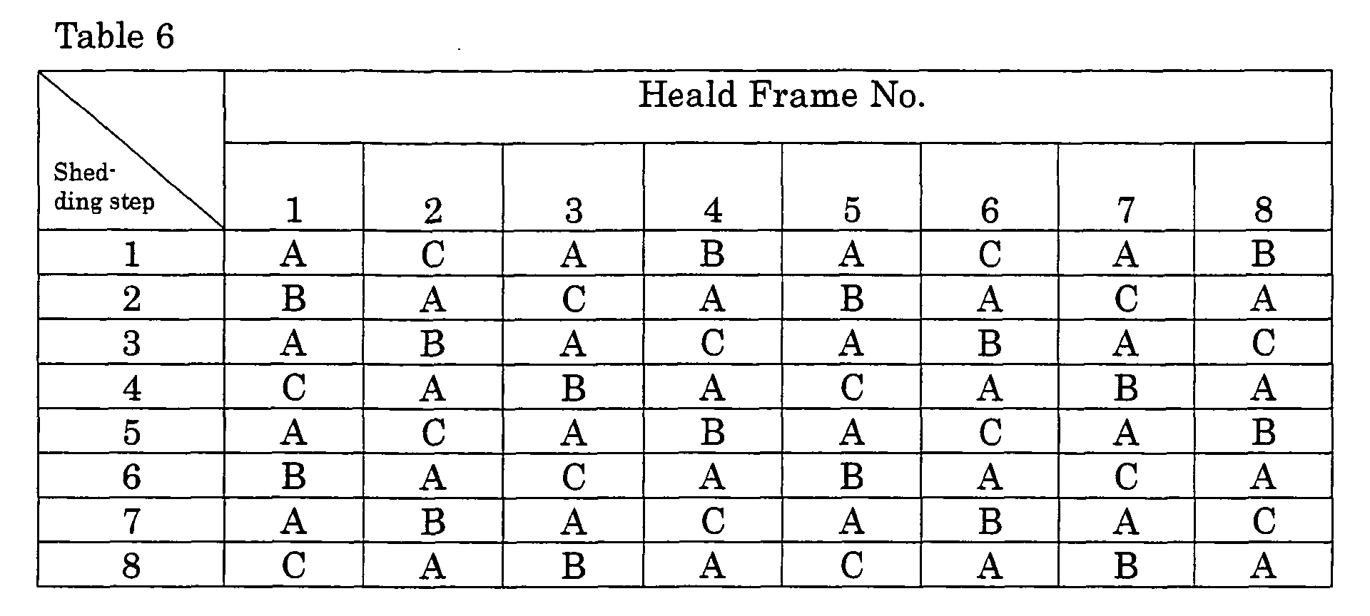
restriction value S2 corresponding to the rank as shown in Table 6 in each
shedding step to each heald frame.
The above-mentioned control device 30 (torque restriction value
generator 74) may be changed as follows.
Instead of judging the continuity of the shedding motion during
operation, it is possible to judge preliminarily before operation and to
enable to generate the selection signal relative to the torque restriction
value corresponding to the number of picks, to generate the selection signal
based on the pick count value during operation, and to change the torque
restriction value.
The changeover during weaving operation is not limited to the
continuity of the above-mentioned shedding motion regarding a weaving
element, but the torque restriction value may be determined, taking into
account of the following, and two or more may be combined.
For example, like the first embodiment, by determining the factor for
computing the torque restriction value preliminarily to meet a setting mode
of the weaving element to be mentioned later, the torque restriction value
is obtained and set from the factor selected in correspondence to the setting
mode of each weaving element. It is desirable to set the torque restriction
value in such a case by preliminarily obtaining the torque restriction value
in correspondence to a combination of each setting mode prior to weaving
operation and to set by selecting them during weaving operation, but it is
possible to set it by calculation every time the setting mode is changed over
during weaving operation.
For example, it is possible to select a dwell angle (an angle for
maintaining in the maximum shedding state) during weaving operation, a
cross timing of the shedding motion, and shedding curves different in
composing elements of the shedding curves such as shedding amount. In
this case, it suffices to set a torque restriction value according to a shedding
curve and to change over; for example, when selecting a shedding curve
with a shortened driving period, the torque restriction value may be set on
the high side.
The torque restriction value may be changed to correspond to the
moving direction of the heald frame 36 (from top to bottom or from bottom
to top). More concretely, in case the dead load of the heald frame 36 acts
greatly on the rotation of the electric motor 38, the torque restriction value
may be set on the low side.
In order to improve weft placing property, the warp tension is
changed according to the weft inserting pick during operation of the loom.
The above-mentioned torque restriction value of the shedding device may
be changed over in correspondence to such a change. More concretely,
when the warp tension is lowered, the torque restriction value is also set on
the low side.
In order to insert plural kinds of wefts different in difficulty in weft
insertion, when changing the rotational speed of the main shaft 32 of the
loom in correspondence to the weft insertion pick during weaving operation,
the torque restriction value is changed over in correspondence to the
change. More concretely, when the rotational speed of the main shaft 32 is
slow, the torque restriction value is set on the low side. In this case, in
step 102 shown in Fig. 11, in the control device 30 of the electric shedding
device, flag A is "off" in step 101, and when a change in rotational speed of
the main shaft 32 is judged in step 102 and in case the rotational speed of
the main shaft 32 is judged to have changed, shifts to step 202 through step
201 of Fig. 12 like when the operation start signal So turned "on."
Regarding changeover of the torque restriction value, in the
above-mentioned second embodiment, the main shaft 32 of the loom is
enabled to change over every time it rotates one round, but it is possible to
change by a predetermined angle of one rotation or less or one rotation or
more, and further, it is possible to change per plural rounds of rotation
such as twice or more.
Changeover of the torque restriction value may be performed by
judging a change in continuity of the shedding motion or may be performed
in correspondence to a changeover of textile of a cloth.
For example, relative to the first process corresponding to the
operation start time in case of a plain weave (namely, during steady
operation, or when the heald frame does not stop and is always moving),
the torque restriction value may be changed over on the low side in the
second process after reaching a steady operational speed.
In case of a loom for changing the rotational speed of the loom
according to the difficulty in weft insertion in correspondence to a change
in rotational speed of the loom, a changeover signal of the rotational speed
of the loom is inputted to the torque restriction value generation circuit as
the torque restriction value generator 74.
While changeover of the torque restriction value may be performed
according to the rotational angle of the main shaft 32, it may be changed
over according to an elapsed time from a reference angle.
Regarding the above-mentioned second embodiment, the torque
restriction value may be set to differ in consideration of the heald frame No.
(frame No.) such as in case of the first embodiment.
The internal constitution of the shedding control device may undergo
a process by hardware concerning a series of processes as illustrated or a
process by a micro-processor as well as software.
The present invention is not limited to the foregoing embodiments but
can be variously changed without departing from its spirit.