EP1541705A2 - Method for processing cylinder periphery, processes for producing development roller and photoconductor drum, and development roller and photoconductor drum - Google Patents
Method for processing cylinder periphery, processes for producing development roller and photoconductor drum, and development roller and photoconductor drum Download PDFInfo
- Publication number
- EP1541705A2 EP1541705A2 EP04027172A EP04027172A EP1541705A2 EP 1541705 A2 EP1541705 A2 EP 1541705A2 EP 04027172 A EP04027172 A EP 04027172A EP 04027172 A EP04027172 A EP 04027172A EP 1541705 A2 EP1541705 A2 EP 1541705A2
- Authority
- EP
- European Patent Office
- Prior art keywords
- roller
- die
- metallic glass
- asperities
- glass film
- Prior art date
- Legal status (The legal status is an assumption and is not a legal conclusion. Google has not performed a legal analysis and makes no representation as to the accuracy of the status listed.)
- Withdrawn
Links
- 238000000034 method Methods 0.000 title claims abstract description 49
- 239000005300 metallic glass Substances 0.000 claims abstract description 98
- 239000012530 fluid Substances 0.000 claims abstract description 14
- 238000010438 heat treatment Methods 0.000 claims abstract description 14
- 238000007751 thermal spraying Methods 0.000 claims abstract description 13
- 238000005096 rolling process Methods 0.000 claims abstract description 10
- 239000007788 liquid Substances 0.000 claims abstract description 8
- 229910052751 metal Inorganic materials 0.000 claims description 14
- 239000002184 metal Substances 0.000 claims description 14
- 239000004033 plastic Substances 0.000 claims description 7
- 229910052782 aluminium Inorganic materials 0.000 claims description 6
- 229910052759 nickel Inorganic materials 0.000 claims description 5
- 239000011261 inert gas Substances 0.000 claims description 4
- 229910052742 iron Inorganic materials 0.000 claims description 4
- 229910052749 magnesium Inorganic materials 0.000 claims description 4
- 229910052763 palladium Inorganic materials 0.000 claims description 4
- 239000000463 material Substances 0.000 description 9
- 238000005242 forging Methods 0.000 description 8
- 238000004519 manufacturing process Methods 0.000 description 6
- 239000006061 abrasive grain Substances 0.000 description 3
- 239000000919 ceramic Substances 0.000 description 3
- 230000009477 glass transition Effects 0.000 description 3
- 238000003672 processing method Methods 0.000 description 3
- VYPSYNLAJGMNEJ-UHFFFAOYSA-N Silicium dioxide Chemical compound O=[Si]=O VYPSYNLAJGMNEJ-UHFFFAOYSA-N 0.000 description 2
- 239000004411 aluminium Substances 0.000 description 2
- XAGFODPZIPBFFR-UHFFFAOYSA-N aluminium Chemical compound [Al] XAGFODPZIPBFFR-UHFFFAOYSA-N 0.000 description 2
- 239000000470 constituent Substances 0.000 description 2
- 238000010586 diagram Methods 0.000 description 2
- 230000000694 effects Effects 0.000 description 2
- 150000002739 metals Chemical class 0.000 description 2
- 238000003825 pressing Methods 0.000 description 2
- 239000004065 semiconductor Substances 0.000 description 2
- 229910052710 silicon Inorganic materials 0.000 description 2
- 229910052726 zirconium Inorganic materials 0.000 description 2
- 239000006088 Fotoceram Substances 0.000 description 1
- 229910008813 Sn—Si Inorganic materials 0.000 description 1
- 229910000831 Steel Inorganic materials 0.000 description 1
- 238000010521 absorption reaction Methods 0.000 description 1
- 229910045601 alloy Inorganic materials 0.000 description 1
- 239000000956 alloy Substances 0.000 description 1
- 229910003481 amorphous carbon Inorganic materials 0.000 description 1
- 238000007774 anilox coating Methods 0.000 description 1
- 230000015572 biosynthetic process Effects 0.000 description 1
- 230000001427 coherent effect Effects 0.000 description 1
- 239000013078 crystal Substances 0.000 description 1
- 238000005530 etching Methods 0.000 description 1
- 239000011121 hardwood Substances 0.000 description 1
- 229910021421 monocrystalline silicon Inorganic materials 0.000 description 1
- 230000003647 oxidation Effects 0.000 description 1
- 238000007254 oxidation reaction Methods 0.000 description 1
- 230000001590 oxidative effect Effects 0.000 description 1
- 239000000075 oxide glass Substances 0.000 description 1
- 239000011034 rock crystal Substances 0.000 description 1
- 239000010703 silicon Substances 0.000 description 1
- 238000005507 spraying Methods 0.000 description 1
- 238000004544 sputter deposition Methods 0.000 description 1
- 239000010959 steel Substances 0.000 description 1
- 230000003746 surface roughness Effects 0.000 description 1
- 238000007740 vapor deposition Methods 0.000 description 1
Images


Classifications
-
- G—PHYSICS
- G03—PHOTOGRAPHY; CINEMATOGRAPHY; ANALOGOUS TECHNIQUES USING WAVES OTHER THAN OPTICAL WAVES; ELECTROGRAPHY; HOLOGRAPHY
- G03G—ELECTROGRAPHY; ELECTROPHOTOGRAPHY; MAGNETOGRAPHY
- G03G5/00—Recording members for original recording by exposure, e.g. to light, to heat, to electrons; Manufacture thereof; Selection of materials therefor
- G03G5/10—Bases for charge-receiving or other layers
- G03G5/102—Bases for charge-receiving or other layers consisting of or comprising metals
-
- C—CHEMISTRY; METALLURGY
- C23—COATING METALLIC MATERIAL; COATING MATERIAL WITH METALLIC MATERIAL; CHEMICAL SURFACE TREATMENT; DIFFUSION TREATMENT OF METALLIC MATERIAL; COATING BY VACUUM EVAPORATION, BY SPUTTERING, BY ION IMPLANTATION OR BY CHEMICAL VAPOUR DEPOSITION, IN GENERAL; INHIBITING CORROSION OF METALLIC MATERIAL OR INCRUSTATION IN GENERAL
- C23C—COATING METALLIC MATERIAL; COATING MATERIAL WITH METALLIC MATERIAL; SURFACE TREATMENT OF METALLIC MATERIAL BY DIFFUSION INTO THE SURFACE, BY CHEMICAL CONVERSION OR SUBSTITUTION; COATING BY VACUUM EVAPORATION, BY SPUTTERING, BY ION IMPLANTATION OR BY CHEMICAL VAPOUR DEPOSITION, IN GENERAL
- C23C4/00—Coating by spraying the coating material in the molten state, e.g. by flame, plasma or electric discharge
- C23C4/02—Pretreatment of the material to be coated, e.g. for coating on selected surface areas
-
- C—CHEMISTRY; METALLURGY
- C23—COATING METALLIC MATERIAL; COATING MATERIAL WITH METALLIC MATERIAL; CHEMICAL SURFACE TREATMENT; DIFFUSION TREATMENT OF METALLIC MATERIAL; COATING BY VACUUM EVAPORATION, BY SPUTTERING, BY ION IMPLANTATION OR BY CHEMICAL VAPOUR DEPOSITION, IN GENERAL; INHIBITING CORROSION OF METALLIC MATERIAL OR INCRUSTATION IN GENERAL
- C23C—COATING METALLIC MATERIAL; COATING MATERIAL WITH METALLIC MATERIAL; SURFACE TREATMENT OF METALLIC MATERIAL BY DIFFUSION INTO THE SURFACE, BY CHEMICAL CONVERSION OR SUBSTITUTION; COATING BY VACUUM EVAPORATION, BY SPUTTERING, BY ION IMPLANTATION OR BY CHEMICAL VAPOUR DEPOSITION, IN GENERAL
- C23C4/00—Coating by spraying the coating material in the molten state, e.g. by flame, plasma or electric discharge
- C23C4/18—After-treatment
-
- G—PHYSICS
- G03—PHOTOGRAPHY; CINEMATOGRAPHY; ANALOGOUS TECHNIQUES USING WAVES OTHER THAN OPTICAL WAVES; ELECTROGRAPHY; HOLOGRAPHY
- G03G—ELECTROGRAPHY; ELECTROPHOTOGRAPHY; MAGNETOGRAPHY
- G03G15/00—Apparatus for electrographic processes using a charge pattern
- G03G15/06—Apparatus for electrographic processes using a charge pattern for developing
- G03G15/08—Apparatus for electrographic processes using a charge pattern for developing using a solid developer, e.g. powder developer
- G03G15/0806—Apparatus for electrographic processes using a charge pattern for developing using a solid developer, e.g. powder developer on a donor element, e.g. belt, roller
- G03G15/0818—Apparatus for electrographic processes using a charge pattern for developing using a solid developer, e.g. powder developer on a donor element, e.g. belt, roller characterised by the structure of the donor member, e.g. surface properties
-
- Y—GENERAL TAGGING OF NEW TECHNOLOGICAL DEVELOPMENTS; GENERAL TAGGING OF CROSS-SECTIONAL TECHNOLOGIES SPANNING OVER SEVERAL SECTIONS OF THE IPC; TECHNICAL SUBJECTS COVERED BY FORMER USPC CROSS-REFERENCE ART COLLECTIONS [XRACs] AND DIGESTS
- Y10—TECHNICAL SUBJECTS COVERED BY FORMER USPC
- Y10T—TECHNICAL SUBJECTS COVERED BY FORMER US CLASSIFICATION
- Y10T29/00—Metal working
- Y10T29/49—Method of mechanical manufacture
- Y10T29/49544—Roller making
- Y10T29/4956—Fabricating and shaping roller work contacting surface element
- Y10T29/49563—Fabricating and shaping roller work contacting surface element with coating or casting about a core
Definitions
- the present invention relates to a method for processing the periphery of various types of rollers used in copying machines, printers, and the like, such as photoconductor drums and development rollers, process for producing a development roller and a photoconductor drum, and the development roller and the photoconductor drum.
- a photoconductor drum includes a conductive layer, an underlayer, a charge generation layer, a charge transport layer, and so forth, in that order, on a base material.
- a laser beam which is coherent monochromatic light, emitted to the surface of the photoconductor drum reflects from each interface between the layers and the interface between the base material and the conductive layer, and the reflected rays can interfere with one another. This interference appears as so-called interference fringes on formed visible images, and thus causes image failure.
- the interference particularly affects the formation of high-gradient halftone images.
- the periphery of the base material is processed to have microscopic asperities.
- a pattern of microscopic asperities is transferred to the periphery of a cylindrical metal tube or cylindrical metal column with the use of hardened forging rolls whose peripheries are sandblasted to pattern microscopic asperities, by pressing the roll surfaces on an object, that is, the cylindrical metal tube or cylindrical metal column, and rolling the rolls on the object (Patent Document 1).
- Patent Document 1 Japanese Unexamined Patent Application Publication No. 10-104988
- the periphery of the metal cylinder is provided with asperities of several micrometers by forging.
- the forging requires considerable pressure, and forging apparatuses are inevitably upsized, accordingly.
- Microscopic asperities as small as several micrometers are difficult to transfer in the same shape as the pattern of the forging die.
- the forging die is hardened, it is worn away with hard objects made of metal, and its lifetime is short accordingly.
- the present invention is intended to overcome the above-described disadvantage, and the object of the present invention is to provide: a method for processing cylinder peripheries, capable of highly precise, stable transfer; a process for producing a development roller and a photoconductor drum; and the development roller and the photoconductor drum produced by the process.
- asperities formed on a die are transferred to a metallic glass film formed on the periphery of a cylindrical column-shaped or cylindrical tube-shaped core of a roller by: heating the metallic glass film to turn into a viscous fluid; and rotating or rolling the roller while the metallic glass film is pressed against the die having asperities.
- the metallic glass film formed on the periphery of the cylindrical column-shaped or cylindrical tube-shaped core is turned into a viscous fluid, and the asperities of the die are transferred to the metallic glass film by rotating or rolling the roller while the roller is pressed against the die, highly precise, stable transfer can be achieved. Since it suffices that the die has a certain degree of hardness, the invention extends the range of choice in the metal used as the die. Accordingly, the die can be prepared by many processing methods, and thus the range of choice in producing the die extends. Also, since the pressure of the roller on the die is much smaller than that of conventional forging, the wear of the die is reduced, and the lifetime of the die increases accordingly. Thus, energy saving and downsizing of the manufacturing apparatus can be achieved. Furthermore, since the metallic glass is of amorphous metal, nanometer-level transfer can be achieved, and thus nanoscopic asperities can be accurately transferred.
- the foregoing method may include the step of forming the metallic glass film on the periphery of the core.
- a metallic glass in a liquid form is thermal-sprayed on the periphery of the core, thereby forming the metallic glass film. Since the metallic glass film is formed by thermal spraying, processing time can be reduced.
- the thermal spraying is performed in an inert gas atmosphere. Since the thermal spraying is performed in an inert gas atmosphere, the metallic glass is prevented from oxidizing.
- the metallic glass contains at least one group selected from among Zr, Ni, Al, Pd, Mg, Fe, Co, and Ti groups.
- various types of material can be used as the metallic glass, and thus the range of choices extends.
- the material of the metallic glass can be selected according to the material of the core.
- At least the periphery is made of metal, ceramic, or plastic. Ceramic and plastic can be used as the material of the core, in addition to metal. Use of plastic can achieve light weight of the core.
- One or both of the core and the die may be heated to heat the metallic glass film.
- the core and the die may be heated.
- the heating may be performed by using infrared rays, a heater, or a furnace.
- the die may be in a plate form, and the asperities on the surface of the die may be transferred to the surface of the roller by rotating or rolling the roller while the roller is pressed against the die.
- the asperities on the surfaces of two plate-like dies may be transferred to the surface of the roller by rotating or rolling the roller with the roller pinched between the two dies.
- the die may be in a cylindrical column or cylindrical tube form, and the asperities on the surface of the die may be transferred to the surface of the roller by rotating both the roller and the die while the roller is pressed against the die.
- the asperities on the surfaces of two cylindrical column-shaped or cylindrical tube-shaped dies may be transferred to the surface of the roller by rotating both the roller and the dies with the roller pinched between the two dies.
- the die may be in a disk form, and the asperities on the side wall of the die may be transferred to the surface of the roller by rotating both the roller and the die while the roller is pressed against the side wall of the die.
- the asperities on the side walls of two disk-shaped dies may be transferred to the surface of the roller by rotating both the roller and the dies with the roller pinched between the two dies.
- a process for producing a development roller according to the present invention includes the step of processing the periphery of the development roller by the method for processing cylinder peripheries.
- the periphery of the development roller is appropriately processed to eliminate causes of image failure.
- a process for producing a photoconductor drum according to the present invention includes the step of processing the periphery of the photoconductor drum by the method for processing cylinder peripheries.
- the periphery of the photoconductor drum is appropriately processed to eliminate causes of image failure.
- a development roller according to the present invention is produced by the foregoing production process of a development roller.
- a photoconductor drum according to the present invention is produced by the foregoing production process of a photoconductor drum.
- the development roller according to the present invention includes a cylindrical column-shaped or cylindrical tube-shaped core and a metallic glass film formed on the periphery of the core.
- the metallic glass has asperities on its surface.
- the photoconductor drum according to the present invention includes a cylindrical column-shaped or cylindrical tube-shaped core and a metallic glass film formed on the periphery of the core.
- the metallic glass has asperities on its surface.
- the present embodiment describes a process for producing a development roller used in a printer, in sections: (a) step of forming a metallic glass film on the periphery of a core serving as a roller; (b) step of producing a die; (c) step of heating the die; and (d) step of transfer.
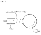
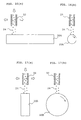
- Figs. 1, 2, and 3 show the step of forming a metallic glass film on the periphery of a core serving as a roller.
- Fig. 1 is a perspective view of a cylindrical column-like or cylindrical tube-like core 10.
- Fig. 2 is a representation of thermal spraying in which a metallic glass 14 melted into liquid is sprayed onto the core 10 from a nozzle 12, and
- Fig. 3 is an enlarged view of the thermal spraying.
- the cylindrical column-like or cylindrical tube-like core 10 is prepared as a base material of the development roller.
- the base material 10 is made of, for example, aluminium, and, in the present embodiment, has a diameter of about 18 mm.
- the liquid of metallic glass 14 is sprayed from the nozzle 12 onto the periphery of the rotating core 10 with a temperature of about room temperature while the nozzle 12 is moved in the direction of the shaft of the core 10, thus forming a metallic glass film 16 on the periphery of the core 10.
- Spraying the liquid of metallic glass 14 is herein referred to as thermal spraying.
- the metallic glass 14 landed on the periphery of the core roller 10 by thermal spraying is rapidly cooled and solidified in an amorphous state to adhere to the periphery.
- a roller 18 which has the metallic glass film 16 on the periphery of the core 10. Any technique can be applied to the thermal spraying, but preferably, it is performed in an atmosphere of inert gas (such as N 2 or Ar) so as to prevent oxidation of the metallic glass 14 and the metallic glass film 16.
- inert gas such as N 2 or Ar
- the thickness of the metallic glass film 16 is set according to the depth of the asperities formed in the metallic glass film 16. In the present embodiment, it is set at, for example, about 50 ⁇ m.
- the periphery of the roller 18 to which the metallic glass 14 was thermal-sprayed often has asperities or very small holes. Accordingly, the periphery is preferably grinded or polished to increase the roundness and to make smooth the surface of the metallic glass film 16.
- step (a) is not necessary.
- metallic glass is an amorphous metal containing a Zr, Ni, Al, Pd, Mg, Fe, Co, or Ti group or the like and is thus metal, as well known, it turns into viscous fluid at a temperature of glass transition temperature or higher, like oxide glass.
- the present invention utilizes this property.
- the metallic glass include Zr 55 Al 10 Cu 30 Ni 5 , Pd 40 Cu 30 Ni 10 P 20 (numerals represent atomic ratios), and other alloys, such as Pd-Ni-Fe-P, Pd-Cu-B-Si, Al-Cs-Ni, and Ni-Zr-Ti-Sn-Si.
- Zr 55 Al 10 Cu 30 Ni 5 is used as the metallic glass 14.
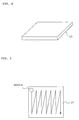
- Figs. 4, 5, and 6 shows the step of producing a die used for transfer.
- Fig. 4 is a perspective view of a plate (for example SUS 316) for forming the die
- Figs. 5 and 6 are representations of the plate which is being processed.
- a plate (plate-like base) 20 is prepared as the base of the die.
- Abrasive grains 24 are jetted from a nozzle 22 over the entire surface of the plate 20 to sandblast the surface of the plate 20, thereby forming a plurality of microscopic asperities 26a on its surface.
- plate-like die 26 is prepared.
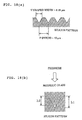
- Fig. 7 is an enlarged sectional view of the plate-like die 26.
- the above-described sandblast treatment provides the asperities 26a having an average surface roughness Rz of 6.0 to 6.5 ⁇ m.
- the step of producing the die is generally not included in a process of transfer to the metallic glass film 16 of the roller 18 (this applies to other embodiments).
- Fig. 8 is a representation of the step of heating the die 26.
- the die 26 is placed on a heater 28 and heated to a temperature of, for example, 460 to 470°C.
- the heating of the die 26 is performed in order to turn the metallic glass film 16 into a viscous fluid by heating the roller 18 (particularly the metallic glass film 16) with the heated die 26 to a temperature of glass transition temperature (Tg) or more in the step of transfer shown in Fig. 9, described later.
- Tg glass transition temperature
- the glass transition temperature (Tg) depends on the constituents of the metallic glass, and the heating temperature of the die 26 is set according to the metallic glass used.
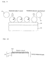
- Fig. 9 is a representation of the step of transferring the asperities 26a of the die 26 to the roller 18 prepared as above.
- the roller 18 is moved down to press the die 26 which is heated to a temperature in the foregoing range with the heater 28.
- the pressure at this point is about 100 MP, for instance.
- the roller 18 is rolled on the die 26 while pressing the die. In this instance, the moving speed of the rolling is, for example, about 30 mm/min.
- the pressure is released and the roller 26 is taken off from the die 26.
- the asperities 26a (or asperity pattern) on the surface of the die 26 of the roller 18 are transferred to the metallic glass film 16 to produce a development roller 30.
- Fig. 10 is an enlarged sectional view of the vicinity of the surface of the development roller 30 produced as above.
- the asperities 26a of the die 26 are transferred to the metallic glass film 16 of the development roller 30, and thus asperities 30a (or an asperity pattern) are formed.
- the Rz of the asperities 30a is, for example, 6.0 to 6.5 ⁇ m; hence, the asperities 20a of the die 26 have been precisely transferred. The precision of the transfer will be described in detail in an example later.
- Embodiment 1 the roller 18 having the metallic glass film 16 on its periphery is pressed against the heated plate-like die 26, and the asperities 26a of the die 26 are transferred to the metallic glass film 16 turned into a viscous fluid by being heated with the heated die 26.
- Embodiment 1 can achieve highly precise and stable transfer. Since it suffices that the die has a certain degree of hardness, the embodiment extends the range of choice in the metal used as the die. Accordingly, the die can be prepared by many processing methods, and thus the range of choice in producing the die extends. Also, since the pressure of the roller 18 on the die 26 is much lower than that of conventional forging, the wear of the die 26 is reduced, and the lifetime of the die increases accordingly.
- the pressure is low, energy saving and downsizing of the manufacturing apparatus can be achieved.
- the metallic glass is of amorphous metal, nanometer-level transfer can be achieved, and thus nanoscopic asperities of the die 26 can be accurately transferred.
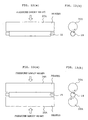
- Fig. 9 shows an example using the single plate-like die 26
- transfer can be performed with two plate-like dies 26.
- the roller 18 is pinched between two plate-like dies 26, and the roller 18 is rotated by moving the dies 26 as shown in Fig. 11.
- the asperities on the surfaces of the dies 26 are transferred to the metallic glass film 16 on the surface of the roller 18.
- the asperities of the dies are transferred to the entire periphery of the roller 18 by only a half-turn of the roller 18. Only either the dies 26 may be moved, or both the dies may be moved.
- a cylindrical column-shaped or cylindrical tube-shaped die 26A can be used to transfer microscopic asperities.
- the cylindrical column-shaped or cylindrical tube-shaped die 26A can be produced through the method shown in Fig. 6. Specifically, abrasive grains 24 are jetted from a nozzle 22 onto the surface of a cylindrical column-shaped or cylindrical tube-shaped base 20A made of SUS 316 or the like to sandblast the surface of the base 20A, thereby forming a plurality of microscopic asperities on its surface.
- cylindrical column-shaped or cylindrical tube-shaped die 26A used for transfer is prepared, as shown in Fig. 16.
- Fig. 16(a) is a front view
- Fig. 16(b) is a side view.
- Fig. 12 shows representations of transfer of asperities to the metallic glass film 16 formed on the surface of the roller 18, using the single cylindrical column-shaped die 26A.
- Fig. 12(a) is a front view
- Fig. 12(b) is a side view.
- the roller 18 and the die 26A which is heated, are rotated with the roller 18 pressed against the die 26A at a pressure of, for example, about 100 MP.
- the asperities of the surface of the die 26A are transferred to the metallic glass film 16 turned into fluid on the surface of the roller 18.
- Fig. 13 shows representations of transfer of asperities to the metallic glass film 16 formed on the surface of the roller 18, using two cylindrical column-shaped dies 26A.
- Fig. 13(a) is a front view
- Fig. 13(b) is a side view.
- both the roller 18 and the dies 26A are rotated with the roller 18 pinched between the two dies 26A at a pressure of, for example, about 100 MP.
- the asperities of the surfaces of the dies 26A are transferred to the metallic glass film 16 turned into fluid on the surface of the roller 18.
- microscopic asperities can be transferred to the metallic glass film 16 on the surface of the roller 18 with use of one or two cylindrical column-shaped or cylindrical tube-shaped dies 26A, and thus substantially the same effect as in Embodiment 1 is produced.
- a method will be described here which performs transfer to the metallic glass film 16 on the surface of the roller 18 with use of a disk-shaped die 26B, instead of the pate-like die 26 or the cylindrical column-shaped or cylindrical tube-shaped die 26A.
- the disk-shaped die 26B can be produced through the method shown in Fig. 6. Specifically, abrasive grains 24 are jetted from a nozzle 22 onto the side wall of a disk-shaped base 20B made of SUS 316 or the like to sandblast the side wall of the base 20B, thereby forming a plurality of microscopic asperities on the side wall.
- a disk-shaped die 26B used for transfer is prepared, as shown in Fig. 17.
- Fig. 17(a) is a front view
- Fig. 17(b) is a side view.
- Fig. 14 shows representations of transfer of asperities to the metallic glass film 16 formed on the surface of the roller 18, using a disk-shaped die 26B.
- Fig. 14(a) is a front view
- Fig. 14(b) is a side view.
- the roller 18 and the die 26B which is heated, are rotated while the roller 18 and the side wall of the die 26B are pressed at a pressure of about 100 MP.
- the asperities of the side wall of the die 26B are transferred to the metallic glass film 16 turned into fluid on the surface of the roller 18.
- Fig. 15 shows representations of transfer of asperities to the metallic glass film 16 formed on the surface of the roller 18, using two disk-shaped dies 26B.
- Fig. 15(a) is a front view
- Fig. 15(b) is a side view.
- both the roller 18 and the dies 26A are rotated with the roller 18 pinched between the two dies 26A at a pressure of, for example, about 100 MP.
- the asperities of the side walls of the dies 26B are transferred to the metallic glass film 16 turned into fluid on the surface of the roller 18.
- roller 18 and the disk-shaped die 26B are moved in the direction designated by the arrow.
- microscopic asperities can be transferred to the metallic glass film 16 on the surface of the roller 18 with use of one or two disk-shaped dies 26B, and thus substantially the same effect as in Embodiment 1 is produced.
- the core 10 of the roller 18 is made of aluminium, it may be made of other metals, or ceramic or plastic. Plastic can achieve light weight and lead to reduced operational power. If plastic is used, the periphery of the core may be plated in order to enhance the adhesion to the metallic glass film 16.
- the die 26, 26A, or 26B heated with a heater 28 heats the metallic glass film 16.
- the metallic glass film 16 may be heated by heating both the roller 18 and the die 26, 26A, or 26B with infrared rays or a furnace. Only the roller 18 may be heated with a hater to turn the metallic glass film 16 into a viscous fluid.
- the die may be made of, for example, SKD, SKH, super-hardwood, quartz glass, amorphous carbon, Fotoceram, or rock crystal, instead of steel. Since the die does not need high strength, single-crystal silicon may be used, for example.
- a single-crystal die can provide a neat pattern by etching. For example, V-shaped grooves at regular intervals and various types of patterns, such as a pyramidal pattern, can be formed. By using the die having such a pattern, a neat, single-size, regular-interval pattern can be precisely transferred to the metallic glass film 16.
- usable metallic glasses for the metallic glass film 16 include other amorphous metals containing at least one group of Ni, Al, Pd, Mg, Fe, Co, Ti, and the like.
- the metallic glass film 16 is formed by thermal-spraying of the metallic glass 14, the metallic glass film 16 may be formed by vapor deposition or sputtering.
- photoconductor drums which have the same structure as the development roller, may be produced in the same manner.
- the above-described production method can be applied to the manufacture of anilox rollers of laser printers.
- Figs. 18(a) and 18(b) are representations of an example according to Embodiment 1 of the present invention.
- silicon is used as a constituent of a plate-like die 26, and a pattern (asperities) of V-shaped grooves with a width of 8.18 ⁇ m and a P (pitch) of 10 ⁇ m is prepared.
- a roller 18 is pressed against the die 26, as shown in Fig. 18(b).
- the metallic glass film 16 of the roller 18 was formed of a metallic glass Zr 55 Al 10 Cu 30 Ni 5 at a heating temperature of 450°C under a pressure of 60 MPa.
- the depth of the grooves of the die 26 is represented by h1; the height of the transferred projections on the metallic glass film 16 of the roller 18, by h2; and the height ratio, by h2/h1.
- a large height ratio (h2/h1) means a high transfer ratio.
- Fig. 19 is a property diagram showing the relationship between the processing time and the height ratio (h2/h1), and shows that the transfer ratio reaches almost 100% in a processing time of about 5 minutes.
Landscapes
- Chemical & Material Sciences (AREA)
- Physics & Mathematics (AREA)
- Engineering & Computer Science (AREA)
- Metallurgy (AREA)
- Chemical Kinetics & Catalysis (AREA)
- Materials Engineering (AREA)
- Mechanical Engineering (AREA)
- General Physics & Mathematics (AREA)
- Organic Chemistry (AREA)
- Plasma & Fusion (AREA)
- Shaping Of Tube Ends By Bending Or Straightening (AREA)
- Application Of Or Painting With Fluid Materials (AREA)
- Magnetic Brush Developing In Electrophotography (AREA)
- Discharging, Photosensitive Material Shape In Electrophotography (AREA)
- Electrophotography Configuration And Component (AREA)
- Rolls And Other Rotary Bodies (AREA)
- Developing Agents For Electrophotography (AREA)
Abstract
Description
Claims (20)
- A method for processing cylinder peripheries characterized in that asperities formed on a die are transferred to a metallic glass film formed on the periphery of a cylindrical column-shaped or cylindrical tube-shaped core of a roller by: heating the metallic glass film to turn into a viscous fluid; and rotating or rolling the roller while the metallic glass film is pressed against the die having the asperities.
- The method for processing cylinder peripheries according to Claim 1, the method includes the step of forming the metallic glass film on the periphery of the core.
- The method for processing cylinder peripheries according to Claim 2, wherein a metallic glass in a liquid form is thermal-sprayed on the periphery of the core, thereby forming the metallic glass film.
- The method for processing cylinder peripheries according to Claim 3, wherein the thermal spraying is performed in an inert gas atmosphere.
- The method for processing cylinder peripheries according to any one of Claims 1 to 4, wherein the metallic glass contains at least one group selected from among Zr, Ni, Al, Pd, Mg, Fe, Co, and Ti groups.
- The method for processing cylinder peripheries according to any one of Claims 1 to 5, wherein, in the core, at least the periphery thereof comprises a metal or a plastic.
- The method for processing cylinder peripheries according to any one of Claims 1 to 6, wherein at least either the core or the die is heated to heat the metallic glass film.
- The method form processing cylinder peripheries according to Claim 7, wherein the heating is performed by using any one of infrared rays, a hater, or a furnace.
- The method for processing cylinder peripheries according to any one of Claims 1 to 8, wherein the die is in a plate form, and the asperities on the surface of the die are transferred to the surface of the roller by rotating or rolling the roller while the roller is pressed against the die.
- The method for processing cylinder peripheries according to any one of Claims 1 to 8, wherein the die is in a plate form, and the asperities on the surfaces of two dies are transferred to the surface of the roller by rotating or rolling the roller with the roller pinched between the dies.
- The method for processing cylinder peripheries according to any one of Claims 1 to 8, wherein the die is in a cylindrical column or cylindrical tube form, and the asperities on the surface of the die are transferred to the surface of the roller by rotating both the roller and the die while the roller is pressed against the die.
- The method for processing cylinder peripheries according to any one of Claims 1 to 8, wherein the die is in a cylindrical column or cylindrical tube form, and the asperities on the surfaces of two dies are transferred to the surface of the roller by rotating both the roller and the dies with the roller pinched between the dies.
- The method for processing cylinder peripheries according to any one of Claims 1 to 8, wherein the die is in a disk form, and the asperities on the side wall of the die are transferred to the surface of the roller by rotating both the roller and the die while the roller is pressed against the side wall of the die.
- The method for processing cylinder peripheries according to any one of Claims 1 to 8, wherein the die is in a disk form, and the asperities on the side walls of two dies are transferred to the surface of the roller by rotating both the roller and the dies with the roller pinched between the side walls of the dies.
- A process for producing a development roller, the process including the step of processing the periphery of the development roller by the method for processing cylinder peripheries as set forth in any one of Claims 1 to 14.
- A process for producing a photoconductor drum, the process including the step of processing the periphery of the photoconductor drum by the method for processing cylinder peripheries as set forth in any one of Claims 1 to 14.
- A development roller produced by the process for producing a development roller as set forth in Claim 15.
- A photoconductor drum produced by the process for producing a photoconductor drum as set forth in Claim 16.
- A development roller comprising:a cylindrical column-shaped or cylindrical tube-shaped core: anda metallic glass film formed on the periphery of the core, the metallic glass film having asperities on the surface thereof.
- A photoconductor drum comprising:a cylindrical column-shaped or cylindrical tube-shaped core: anda metallic glass film formed on the periphery of the core, the metallic glass film having asperities on the surface thereof.
Applications Claiming Priority (4)
| Application Number | Priority Date | Filing Date | Title |
|---|---|---|---|
| JP2003392032 | 2003-11-21 | ||
| JP2003392032 | 2003-11-21 | ||
| JP2004295773 | 2004-10-08 | ||
| JP2004295773A JP2005173558A (en) | 2003-11-21 | 2004-10-08 | Circumferential surface processing method, developing roller and photosensitive drum manufacturing method, developing roller and photosensitive drum |
Publications (2)
| Publication Number | Publication Date |
|---|---|
| EP1541705A2 true EP1541705A2 (en) | 2005-06-15 |
| EP1541705A3 EP1541705A3 (en) | 2005-07-06 |
Family
ID=34525480
Family Applications (1)
| Application Number | Title | Priority Date | Filing Date |
|---|---|---|---|
| EP04027172A Withdrawn EP1541705A3 (en) | 2003-11-21 | 2004-11-16 | Method for processing cylinder periphery, processes for producing development roller and photoconductor drum, and development roller and photoconductor drum |
Country Status (4)
| Country | Link |
|---|---|
| US (1) | US20050113230A1 (en) |
| EP (1) | EP1541705A3 (en) |
| JP (1) | JP2005173558A (en) |
| CN (1) | CN100353260C (en) |
Families Citing this family (12)
| Publication number | Priority date | Publication date | Assignee | Title |
|---|---|---|---|---|
| KR101247410B1 (en) * | 2004-03-25 | 2013-03-25 | 가부시키가이샤 토호쿠 테크노 아치 | Metallic glass laminate, process for producing the same and use thereof |
| TWI346092B (en) * | 2004-03-31 | 2011-08-01 | Konica Minolta Opto Inc | Manufacturing method of die for optical element molding |
| US7353605B2 (en) * | 2004-07-30 | 2008-04-08 | Eastman Kodak Company | Method for producing a metallic core for use in cylinder sleeves for an electrophotographic process |
| US8052590B2 (en) * | 2005-07-07 | 2011-11-08 | Xerox Corporation | Amorphous metal components for a reproduction machine |
| JP4889271B2 (en) * | 2005-09-26 | 2012-03-07 | 国立大学法人東北大学 | Metal glass composite material and member for electronic and electrical equipment using the same |
| JP4059518B2 (en) | 2006-01-31 | 2008-03-12 | キヤノン株式会社 | Method for producing electrophotographic photosensitive member |
| JP4783934B2 (en) | 2009-06-10 | 2011-09-28 | 株式会社丸ヱム製作所 | Metal glass fastening screw |
| JP5318204B2 (en) | 2009-12-04 | 2013-10-16 | キヤノン株式会社 | Electrophotographic photosensitive member, process cartridge, and electrophotographic apparatus |
| US20140010968A1 (en) * | 2012-07-04 | 2014-01-09 | Christopher D. Prest | Flame sprayed bulk solidifying amorphous alloy cladding layer |
| CN102967279A (en) * | 2012-11-22 | 2013-03-13 | 南京理工大学 | Method for accurately determining surface roughness through adopting amorphous alloy |
| CN107398379B (en) * | 2017-08-15 | 2018-11-27 | 江苏诺德新材料股份有限公司 | Integral type prepreg gluing machine roll shaft spraying mechanism |
| JP7240124B2 (en) * | 2017-10-16 | 2023-03-15 | キヤノン株式会社 | Electrophotographic photoreceptor, process cartridge and electrophotographic apparatus |
Family Cites Families (23)
| Publication number | Priority date | Publication date | Assignee | Title |
|---|---|---|---|---|
| US1662295A (en) * | 1926-03-08 | 1928-03-13 | Marietta Mfg Co | Process of making decorated glassware |
| US1810636A (en) * | 1930-12-29 | 1931-06-16 | Silk City Metals Coating Compa | Textile roll |
| US3156033A (en) * | 1962-01-02 | 1964-11-10 | Smith Corp A O | Method and apparatus for forming a glass coated tubular roller element |
| US3214310A (en) * | 1962-06-29 | 1965-10-26 | Modern Engraving And Machine C | Method of making embossing rolls by engraving mills |
| US3550258A (en) * | 1967-06-23 | 1970-12-29 | Polaroid Corp | Method of manufacturing a roller |
| US3447221A (en) * | 1967-06-23 | 1969-06-03 | Polaroid Corp | Roller structure and method of manufacture |
| US4562090A (en) * | 1983-11-30 | 1985-12-31 | Gray Tool Company | Method for improving the density, strength and bonding of coatings |
| DE3524018A1 (en) * | 1985-07-02 | 1987-01-15 | Mannesmann Ag | Process and device for producing metal glass |
| US4692305A (en) * | 1985-11-05 | 1987-09-08 | Perkin-Elmer Corporation | Corrosion and wear resistant alloy |
| US4810547A (en) * | 1986-03-26 | 1989-03-07 | Nippon Sheet Glass Co., Ltd. | Substrate with fine grooves and method for manufacturing the same |
| DE3810851C2 (en) * | 1988-03-30 | 1995-09-28 | Thyssen Guss Ag | Process for the production of molded parts |
| US4965139A (en) * | 1990-03-01 | 1990-10-23 | The United States Of America As Represented By The Secretary Of The Navy | Corrosion resistant metallic glass coatings |
| JP2995236B2 (en) * | 1990-08-10 | 1999-12-27 | 株式会社ナカシマ | Method for producing metal roll material having glass surface |
| FR2691478B1 (en) * | 1992-05-22 | 1995-02-17 | Neyrpic | Metallic coatings based on amorphous alloys resistant to wear and corrosion, ribbons obtained from these alloys, process for obtaining and applications to wear-resistant coatings for hydraulic equipment. |
| JP2905672B2 (en) * | 1992-09-04 | 1999-06-14 | キヤノン株式会社 | Cylindrical body and drum base for electrophotographic apparatus, method for holding the same, manufacturing method and processing apparatus |
| JPH0966401A (en) * | 1995-06-21 | 1997-03-11 | Canon Inc | Cylindrical member, its manufacturing method and manufacturing apparatus |
| US5932293A (en) * | 1996-03-29 | 1999-08-03 | Metalspray U.S.A., Inc. | Thermal spray systems |
| JPH10104988A (en) * | 1996-10-02 | 1998-04-24 | Canon Inc | Metal peripheral surface processing method and its processed product |
| JP2000167484A (en) * | 1998-11-30 | 2000-06-20 | Nakashima:Kk | Glass melt-spraying method and device |
| US6733891B1 (en) * | 2000-05-31 | 2004-05-11 | Xerox Corporation | Roll having glass coating |
| JP4110506B2 (en) * | 2001-11-21 | 2008-07-02 | コニカミノルタホールディングス株式会社 | Mold for optical element molding |
| ATE412256T1 (en) * | 2002-06-07 | 2008-11-15 | Fujifilm Corp | METHOD FOR PRODUCING STRUCTURED LAYERS |
| WO2005012591A1 (en) * | 2003-08-05 | 2005-02-10 | Nikko Materials Co., Ltd. | Sputtering target and method for production thereof |
-
2004
- 2004-10-08 JP JP2004295773A patent/JP2005173558A/en not_active Withdrawn
- 2004-11-01 US US10/978,924 patent/US20050113230A1/en not_active Abandoned
- 2004-11-16 EP EP04027172A patent/EP1541705A3/en not_active Withdrawn
- 2004-11-18 CN CNB2004100949338A patent/CN100353260C/en not_active Expired - Fee Related
Also Published As
| Publication number | Publication date |
|---|---|
| US20050113230A1 (en) | 2005-05-26 |
| JP2005173558A (en) | 2005-06-30 |
| EP1541705A3 (en) | 2005-07-06 |
| CN1619435A (en) | 2005-05-25 |
| CN100353260C (en) | 2007-12-05 |
Similar Documents
| Publication | Publication Date | Title |
|---|---|---|
| EP1541705A2 (en) | Method for processing cylinder periphery, processes for producing development roller and photoconductor drum, and development roller and photoconductor drum | |
| Pettersson et al. | Tribological texturing of steel surfaces with a novel diamond embossing tool technique | |
| US5789066A (en) | Method and device for manufacturing cold rolled metal sheets or strips and metal sheets or strips obtained | |
| US20070042129A1 (en) | Embossing assembly and methods of preparation | |
| TWI556941B (en) | Methods of impringting abutted fields on a substrate | |
| US20060144093A1 (en) | Molding die for optical element, optical element and master die | |
| CN1941092A (en) | Stamper, method of manufacturing same, and method of manufacturing magnetic recording media by using the stamper | |
| JPH09502661A (en) | METHOD AND APPARATUS FOR PRODUCING COLD ROLLED METAL SHEET OR STRIPE AND RESULTING METAL SHEET OR STRIPE | |
| JP5256743B2 (en) | Roll mold for optical film production | |
| JPH06345593A (en) | Shaping of article containing polycrystalline diamond and diamond | |
| JP2005133166A (en) | Stamper for pattern transfer, and its production method | |
| JP5403422B2 (en) | Method for producing mold for antiglare film and method for producing antiglare film | |
| JP2000039702A (en) | Transfer and processing method of fine pattern | |
| JP5188364B2 (en) | Laser processing method | |
| JP2009050988A (en) | Method for manufacturing cylindrical substrate | |
| JP4847706B2 (en) | Transfer method to metal plate surface | |
| JP4774889B2 (en) | Manufacturing method of mold for optical component | |
| JP4942131B2 (en) | Stamper and nanostructure transfer method using the same | |
| EP1796860B1 (en) | Modifying surfaces of work-pieces and forming tools | |
| US20070137038A1 (en) | Work rolls having an engineered surface texture prepared by controlled surface modification after chrome coating | |
| JPH0413053B2 (en) | ||
| JP2005353129A (en) | Method for manufacturing substrate for magnetic recording medium, and magnetic recording medium | |
| JP2011257658A (en) | Manufacturing method of electrophotographic photoreceptor | |
| JPH11302746A (en) | Hearth roll for continuous annealing furnace | |
| TWI300019B (en) | Embossing assembly and methods of preparation |
Legal Events
| Date | Code | Title | Description |
|---|---|---|---|
| PUAI | Public reference made under article 153(3) epc to a published international application that has entered the european phase |
Free format text: ORIGINAL CODE: 0009012 |
|
| PUAL | Search report despatched |
Free format text: ORIGINAL CODE: 0009013 |
|
| AK | Designated contracting states |
Kind code of ref document: A2 Designated state(s): AT BE BG CH CY CZ DE DK EE ES FI FR GB GR HU IE IS IT LI LU MC NL PL PT RO SE SI SK TR |
|
| AX | Request for extension of the european patent |
Extension state: AL HR LT LV MK YU |
|
| AK | Designated contracting states |
Kind code of ref document: A3 Designated state(s): AT BE BG CH CY CZ DE DK EE ES FI FR GB GR HU IE IS IT LI LU MC NL PL PT RO SE SI SK TR |
|
| AX | Request for extension of the european patent |
Extension state: AL HR LT LV MK YU |
|
| 17P | Request for examination filed |
Effective date: 20050802 |
|
| AKX | Designation fees paid |
Designated state(s): DE FR GB |
|
| 17Q | First examination report despatched |
Effective date: 20060626 |
|
| 17Q | First examination report despatched |
Effective date: 20060626 |
|
| STAA | Information on the status of an ep patent application or granted ep patent |
Free format text: STATUS: THE APPLICATION HAS BEEN WITHDRAWN |
|
| 18W | Application withdrawn |
Effective date: 20090116 |