EP1541536A1 - Infrared shielding glass - Google Patents
Infrared shielding glass Download PDFInfo
- Publication number
- EP1541536A1 EP1541536A1 EP03771402A EP03771402A EP1541536A1 EP 1541536 A1 EP1541536 A1 EP 1541536A1 EP 03771402 A EP03771402 A EP 03771402A EP 03771402 A EP03771402 A EP 03771402A EP 1541536 A1 EP1541536 A1 EP 1541536A1
- Authority
- EP
- European Patent Office
- Prior art keywords
- infrared shielding
- fine particles
- transmittance
- glass
- ito
- Prior art date
- Legal status (The legal status is an assumption and is not a legal conclusion. Google has not performed a legal analysis and makes no representation as to the accuracy of the status listed.)
- Withdrawn
Links
Images

Classifications
-
- C—CHEMISTRY; METALLURGY
- C03—GLASS; MINERAL OR SLAG WOOL
- C03C—CHEMICAL COMPOSITION OF GLASSES, GLAZES OR VITREOUS ENAMELS; SURFACE TREATMENT OF GLASS; SURFACE TREATMENT OF FIBRES OR FILAMENTS MADE FROM GLASS, MINERALS OR SLAGS; JOINING GLASS TO GLASS OR OTHER MATERIALS
- C03C17/00—Surface treatment of glass, not in the form of fibres or filaments, by coating
- C03C17/006—Surface treatment of glass, not in the form of fibres or filaments, by coating with materials of composite character
- C03C17/008—Surface treatment of glass, not in the form of fibres or filaments, by coating with materials of composite character comprising a mixture of materials covered by two or more of the groups C03C17/02, C03C17/06, C03C17/22 and C03C17/28
-
- C—CHEMISTRY; METALLURGY
- C03—GLASS; MINERAL OR SLAG WOOL
- C03C—CHEMICAL COMPOSITION OF GLASSES, GLAZES OR VITREOUS ENAMELS; SURFACE TREATMENT OF GLASS; SURFACE TREATMENT OF FIBRES OR FILAMENTS MADE FROM GLASS, MINERALS OR SLAGS; JOINING GLASS TO GLASS OR OTHER MATERIALS
- C03C17/00—Surface treatment of glass, not in the form of fibres or filaments, by coating
- C03C17/006—Surface treatment of glass, not in the form of fibres or filaments, by coating with materials of composite character
- C03C17/008—Surface treatment of glass, not in the form of fibres or filaments, by coating with materials of composite character comprising a mixture of materials covered by two or more of the groups C03C17/02, C03C17/06, C03C17/22 and C03C17/28
- C03C17/009—Mixtures of organic and inorganic materials, e.g. ormosils and ormocers
-
- C—CHEMISTRY; METALLURGY
- C03—GLASS; MINERAL OR SLAG WOOL
- C03C—CHEMICAL COMPOSITION OF GLASSES, GLAZES OR VITREOUS ENAMELS; SURFACE TREATMENT OF GLASS; SURFACE TREATMENT OF FIBRES OR FILAMENTS MADE FROM GLASS, MINERALS OR SLAGS; JOINING GLASS TO GLASS OR OTHER MATERIALS
- C03C2217/00—Coatings on glass
- C03C2217/40—Coatings comprising at least one inhomogeneous layer
- C03C2217/43—Coatings comprising at least one inhomogeneous layer consisting of a dispersed phase in a continuous phase
- C03C2217/44—Coatings comprising at least one inhomogeneous layer consisting of a dispersed phase in a continuous phase characterized by the composition of the continuous phase
- C03C2217/445—Organic continuous phases
-
- C—CHEMISTRY; METALLURGY
- C03—GLASS; MINERAL OR SLAG WOOL
- C03C—CHEMICAL COMPOSITION OF GLASSES, GLAZES OR VITREOUS ENAMELS; SURFACE TREATMENT OF GLASS; SURFACE TREATMENT OF FIBRES OR FILAMENTS MADE FROM GLASS, MINERALS OR SLAGS; JOINING GLASS TO GLASS OR OTHER MATERIALS
- C03C2217/00—Coatings on glass
- C03C2217/40—Coatings comprising at least one inhomogeneous layer
- C03C2217/43—Coatings comprising at least one inhomogeneous layer consisting of a dispersed phase in a continuous phase
- C03C2217/46—Coatings comprising at least one inhomogeneous layer consisting of a dispersed phase in a continuous phase characterized by the dispersed phase
- C03C2217/47—Coatings comprising at least one inhomogeneous layer consisting of a dispersed phase in a continuous phase characterized by the dispersed phase consisting of a specific material
- C03C2217/475—Inorganic materials
-
- C—CHEMISTRY; METALLURGY
- C03—GLASS; MINERAL OR SLAG WOOL
- C03C—CHEMICAL COMPOSITION OF GLASSES, GLAZES OR VITREOUS ENAMELS; SURFACE TREATMENT OF GLASS; SURFACE TREATMENT OF FIBRES OR FILAMENTS MADE FROM GLASS, MINERALS OR SLAGS; JOINING GLASS TO GLASS OR OTHER MATERIALS
- C03C2217/00—Coatings on glass
- C03C2217/40—Coatings comprising at least one inhomogeneous layer
- C03C2217/43—Coatings comprising at least one inhomogeneous layer consisting of a dispersed phase in a continuous phase
- C03C2217/46—Coatings comprising at least one inhomogeneous layer consisting of a dispersed phase in a continuous phase characterized by the dispersed phase
- C03C2217/47—Coatings comprising at least one inhomogeneous layer consisting of a dispersed phase in a continuous phase characterized by the dispersed phase consisting of a specific material
- C03C2217/475—Inorganic materials
- C03C2217/476—Tin oxide or doped tin oxide
-
- C—CHEMISTRY; METALLURGY
- C03—GLASS; MINERAL OR SLAG WOOL
- C03C—CHEMICAL COMPOSITION OF GLASSES, GLAZES OR VITREOUS ENAMELS; SURFACE TREATMENT OF GLASS; SURFACE TREATMENT OF FIBRES OR FILAMENTS MADE FROM GLASS, MINERALS OR SLAGS; JOINING GLASS TO GLASS OR OTHER MATERIALS
- C03C2217/00—Coatings on glass
- C03C2217/40—Coatings comprising at least one inhomogeneous layer
- C03C2217/43—Coatings comprising at least one inhomogeneous layer consisting of a dispersed phase in a continuous phase
- C03C2217/46—Coatings comprising at least one inhomogeneous layer consisting of a dispersed phase in a continuous phase characterized by the dispersed phase
- C03C2217/48—Coatings comprising at least one inhomogeneous layer consisting of a dispersed phase in a continuous phase characterized by the dispersed phase having a specific function
- C03C2217/485—Pigments
-
- C—CHEMISTRY; METALLURGY
- C03—GLASS; MINERAL OR SLAG WOOL
- C03C—CHEMICAL COMPOSITION OF GLASSES, GLAZES OR VITREOUS ENAMELS; SURFACE TREATMENT OF GLASS; SURFACE TREATMENT OF FIBRES OR FILAMENTS MADE FROM GLASS, MINERALS OR SLAGS; JOINING GLASS TO GLASS OR OTHER MATERIALS
- C03C2217/00—Coatings on glass
- C03C2217/90—Other aspects of coatings
- C03C2217/94—Transparent conductive oxide layers [TCO] being part of a multilayer coating
Definitions
- the present invention relates to an infrared shielding glass useful particularly as glass for vehicle or glass for building, and a process for its production.
- an infrared shielding glass has been employed for vehicles or buildings for the purpose of shielding infrared rays (heat rays) entering into vehicles or buildings through glass for vehicle or glass for building thereby to prevent a temperature rise in vehicles or buildings and thereby to reduce an air conditioning load.
- Such glass for vehicle or glass for building is required to have a high visible light transmittance in order to secure safety and visibility.
- glass having a high electromagnetic wave transmittance and being capable of reducing electromagnetic disturbance is desired by wide spread use of e.g. mobile phones in recent years.
- a technique to increase the heat ray-shielding property by imparting an infrared shielding property to glass has heretofore already been proposed. For example, it has been proposed to impart an infrared shielding property to glass itself by adding infrared absorptive ions to the glass substrate (e.g. JP-A-4-187539). Further, it has been proposed to impart an infrared shielding property by forming a conductive film on a glass surface (e.g. JP-A-63-206332, JP-A-1-145351 and JP-A-7-315876).
- ITO infrared shielding glass
- ITO is an oxygen-deficient composite oxide, and especially with ITO having a high infrared shielding property, the degree of oxygen deficiency in the crystal lattice is high.
- the high temperature heat treatment is required to be carried out in an atmosphere where no oxygen is present, i.e. in an inert atmosphere or in a reducing atmosphere, such being economically disadvantageous and poor in the productivity.
- the present invention provides the following (1) to (16)
- Fig. 1 is a schematic cross sectional view of the infrared shielding glass of the present invention.
- FIG. 1 A schematic cross sectional view of one embodiment of the infrared shielding glass of the present invention is shown in Fig. 1.
- an infrared shielding glass 10 has a structure comprising a glass substrate 20 having at least one surface thereof coated with a coating liquid containing fine particles of conductive oxide and a matrix component to thereby provide an infrared shielding film 30 .
- the present invention is characterized in that the surface resistivity of the infrared shielding film is increased, and this characteristic is considered to be a result of such that contact of fine particles to one another has been restricted by highly dispersing the fine particles of conductive oxide without agglomeration in the infrared shielding film.
- the infrared shielding film containing the fine particles of conductive oxide is capable of shielding infrared rays by plasma vibration by means of free electrons within the fine particles of conductive oxide, while maintaining the visible light transmittance at a high level.
- the fine particles of conductive oxide in the present invention may, for example, be at least one member selected from the group consisting of fine particles of ATO (antimony-doped tin oxide) and fine particles of fluorine-containing ITO (fluorinated ITO). It is preferred to use fine particles of ATO or fine particles of fluorinated ITO, since it is thereby possible to maintain a high infrared shielding property even after curing the coating material by firing at a high temperature, as described hereinafter, while maintaining the visible light transmittance at a high level. Conventional fine particles of ITO are not preferable, since the heat resistance is low, and the infrared shielding property deteriorates by firing at a high temperature. It is particularly preferred to employ fine particles of fluorinated ITO as the fine particles of conductive oxide, since it is thereby possible to maintain the visible light transmittance at a higher level than the fine particles of ATO.
- ATO antimony-doped tin oxide
- fluorinated ITO fluorine
- the fine particles of ATO in the present invention can be prepared as follows.
- An aqueous solution containing a water-soluble salt of antimony and a water-soluble salt of tin is mixed with an alkaline solution to coprecipitate hydroxides of antimony and tin.
- This co-prepipitate is heated and fired in the atmosphere for conversion to an oxide thereby to prepare an ATO powder.
- the ATO powder prepared by such a method may be used as it is, or an ATO powder commercially available as a conductive powder may be used as it is.
- the antimony content in the ATO powder is preferably from 0.01 to 0.15 as a molar ratio of antimony/(antimony + tin), from the viewpoint of the infrared shielding property.
- the above ATO powder is dispersed in water or in an organic solvent to prepare a dispersion containing fine particles of ATO.
- an organic solvent an alcohol, an ether, a ketone, an ester, an aliphatic hydrocarbon, an aromatic hydrocarbon, etc.
- a dispersant may be added to increase the dispersibility of the dispersion.
- an acryl polymer type dispersant may, for example, be mentioned.
- water it is preferred to adjust the pH to from 2 to 6, from the viewpoint of the dispersibility.
- dispersing treatment may be carried out by means of a device such as ultrasonic irradiation, a homogenizer, a beads mill, a sand mill, a jet mill or a nanomizer.
- a number average dispersed particle diameter may be employed, and it may be measured by e.g. a dynamic light scattering method.
- the number average dispersed particle diameter is preferably at most 200 nm, particularly preferably at most 100 nm, further preferably at most 50 nm, still further preferably at most 30 nm. If the number average dispersed particle diameter exceeds 200 nm, the transparency of the coating film may not be maintained when the film is formed.
- the concentration (solid content concentration) of fine particles of ATO in the above dispersion is preferably from 1 to 50 mass%. If it is less than 1 mass%, the efficiency tends to be poor, and if it exceeds 50 mass%, the dispersion tends to be difficult, such being undesirable.
- the fine particles of fluorinated ITO in the present invention are preferably ones having fluorine introduced into crystal lattice of fine particles of ITO, or ones having fluorine merely adsorbed.
- the fine particles of fluorinated ITO of the present invention may be prepared, for example, as follows.
- an aqueous solution containing a water-soluble salt of indium and a water-soluble salt of tin is mixed with an alkaline solution to coprecipitate indium hydroxide and tin hydroxide.
- This coprecipitate is heated and fired in the atmosphere for conversion to an oxide thereby to form an ITO powder.
- a mixture of such hydroxides but also a mixture of indium hydroxide and/or oxide and tin hydroxide and/or oxide, may widely be used.
- the ITO powder prepared in such a method may be used, or an ITO powder commercially available as a conductive powder may be used as it is.
- the ratio of tin to indium in the above ITO powder is preferably from 0.01 to 0.15 as a molar ratio of tin/(indium + tin) from the viewpoint of the infrared shielding property.
- the above ITO powder is dispersed in a dispersing medium to prepare a dispersion of the fine particles of ITO.
- a dispersing medium may be water or an organic solvent, or a mixed solvent of water and an organic solvent.
- a dispersing medium capable of dispersing the ITO powder with good dispersibility may be employed.
- the organic solvent an alcohol, an ether, a ketone, an ester, an aliphatic hydrocarbon, an aromatic hydrocarbon, etc., may suitably be selected or mixed for use.
- a dispersant may be added to the dispersion to improve the dispersibility of the dispersion.
- an acrylic polymer type dispersant may, for example, be mentioned.
- the pH is preferably adjusted to be from 2 to 6 from the viewpoint of the dispersibility.
- dispersing treatment may be carried out by means of a device such as ultrasonic irradiation, a homogenizer, a beads mill, a sand mill, a jet mill or a nanomizer.
- the concentration (solid content concentration) of the ITO powder in the above dispersion is preferably from 1 to 50 mass%. If this concentration is less than 1 mass%, the efficiency tends to be poor, and if it exceeds 50 mass%, the dispersion tends to be difficult, such being undesirable.
- a fluorine compound is added to the above dispersion to have the fluorine compound adsorbed (impregnated) to the fine particles of ITO thereby to prepare fine particles of fluorinated ITO.
- the fluorine compound may, for example, be an inorganic fluorine compound such as hydrofluoric acid, ammonium fluoride, an alkali metal fluoride (such as lithium fluoride or sodium fluoride), stannous fluoride, stannic fluoride, indium fluoride, ammonium hydrogenfluoride, hydrosilicofluoric acid, ammonium silicofluoride, borohydrofluoric acid, ammonium borofluoride, phosphohydrofluoric acid or ammonium phosphofluoride, or an organic fluorine compound such as a fluorinated resin.
- an inorganic fluorine compound such as hydrofluoric acid, ammonium fluoride, an alkali metal fluoride (such as lithium fluoride or sodium fluoride), stan
- fluorine compounds ammonium fluoride, stannous fluoride, indium fluoride or ammonium silicofluoride is preferably used from the viewpoint of the handling efficiency, impregnation efficiency, etc.
- the fluorine compound may be added to the dispersion as it is. However, it is preferred that a solution having a fluorine compound preliminarily dissolved, is added to the dispersion, since it is thereby possible to uniformly adsorb the fluorine compound to the fine particles of ITO.
- a solution having a fluorine compound preliminarily dissolved is added to the dispersion, since it is thereby possible to uniformly adsorb the fluorine compound to the fine particles of ITO.
- the solvent to have the fluorine compound dissolved therein water, an alcohol, an ether, a ketone, an ester, an aliphatic hydrocarbon, an aromatic hydrocarbon, etc. may be suitably selected or mixed for use, but it is required to be a solvent which can be uniformly mixed with the dispersion.
- the amount of the fluorine compound varies depending upon the type of the fluorine compound and the subsequent treating conditions, but it is preferably from 1 to 100 mass%, based on the fine particles of ITO. If it is less than 1 mass%, the amount of fluorine to be adsorbed, tends to be inadequate, whereby no adequate heat resistance may be obtained. If it exceeds 100 mass%, fluorine tends to be excessive, such being undesirable from the viewpoint of economical efficiency.
- the mixed solution obtained by adding a fluorine compound to the dispersion is subjected to stirring, heat treatment, etc., as the case requires. Thereafter, the solvent in the mixed solution is removed by a known method such as heating at a temperature of not higher than 200°C in the atmosphere under reduced pressure, filtration, centrifugal separation, etc., to obtain an ITO powder having the fluorine compound adsorbed thereon.
- the ITO powder having the fluorine compound adsorbed is then fired in a non-oxidizing atmosphere or in vacuum to form a fluorinated ITO powder.
- the non-oxidizing atmosphere is an atmosphere which does not substantially contain an oxidizing gas such as oxygen or carbon dioxide gas. Specifically, it is preferably one having an oxygen concentration of at most 1.0 vol%, particularly at most 0.1 vol%, with a view to suppressing oxidation of ITO during the firing.
- the non-oxidizing atmosphere includes a non-oxidizing gas such as nitrogen, argon or ammonia.
- a non-oxidizing gas such as nitrogen, argon or ammonia.
- the non-oxidizing atmosphere preferably contains hydrogen, and the content of hydrogen is preferably from 1 to 5 vol%, particularly preferably from 1 to 4 vol%, in the non-oxidizing atmosphere.
- the optimum value varies depending upon the type of the added fluorine compound, but it is usually from 300 to 800°C. If this firing temperature is lower than 300°C, the decomposition of the adsorbed fluorine compound tends to hardly proceed, whereby fluorine tends to hardly be introduced into the ITO powder, and if it exceeds 800°C, no further improvement in the effect for introducing fluorine will be obtained, such being undesirable from the viewpoint of the energy efficiency.
- the time for the firing is preferably from 30 minutes to 24 hours, and after the firing, the powder is preferably cooled in the same non-oxidizing atmosphere to a temperature in the vicinity of room temperature.
- the fluorinated ITO powder produced by the above method is excellent in heat resistance and is useful particularly as an infrared shielding film material for vehicles.
- the content of tin in the fluorinated ITO powder is preferably from 0.01 to 0.15, particularly preferably from 0.04 to 0.12, by a mol ratio of tin/(indium + tin), from the viewpoint of the infrared shielding property.
- the fluorine concentration in the fluorinated ITO powder (i.e. fluorine/(ITO + fluorine)) in the present invention is preferably from 0.1 to 10 mass%, particularly preferably from 1 to 10 mass%, further preferably from 1 to 5 mass%. If the fluorine concentration is less than 0.1 mass%, the effect to improve the heat resistance tends to be low, and if it exceeds 10 mass%, the infrared shielding property itself may deteriorate.
- the mode of incorporation of fluorine may either be a mixed case or an adsorbed case, but fluorine is preferably introduced into the crystal lattice, from the viewpoint of the heat resistance.
- the heat resistance of the fluorinated ITO powder may be estimated by the spectral reflectance of the fluorinated ITO powder.
- a spectral reflectance may be obtained by firstly packing the ITO powder in a cell, and measuring the total diffuse reflection at the surface of the packed ITO powder by a spectrophotometer provided with an integrating sphere in accordance with JIS-Z8722 (2000).
- the maximum wavelength of such a spectral reflectance is closely related with the infrared shielding property of the measured ITO powder, and as the maximum wavelength of the spectral reflectance is located on a short wavelength side, the infrared shielding property will be better. Namely, even after the firing, if the maximum wavelength of the spectral reflectance is on a short wavelength side just like before the firing, such may be regarded as excellent in heat resistance.
- the fluorinated ITO powder has high heat resistance, whereby even if it is fired in the atmosphere at a high temperature, the spectral reflectance will not substantially move to the longer wavelength side.
- firing can efficiently be carried out by employing a heating process for reinforcing processing of a window glass.
- This heating process is carried out, in many cases, in the atmosphere at a temperature of from 600 to 700°C for from 3 to 4 minutes, and taking into consideration the temperature, etc. of this heating process, it is, for example, preferred to evaluate the heat resistance under firing conditions of 700°C for 10 minutes in the atmosphere.
- the fluorinated ITO powder exhibits a spectral reflectance with the maximum wavelength of at most 550 nm and thus has adequate heat resistance.
- the fluorinated ITO powder after the firing is particularly preferably such that the maximum wavelength of its spectral reflectance is at most 500 nm, further preferably at most 460 nm.
- the fine particles of fluorinated ITO in the present invention may be formed by dispersing the fluorinated ITO powder in a dispersion.
- the fine particles of fluorinated ITO are preferably highly dispersed in the coating liquid without agglomeration, and it is preferred to employ a colloidal dispersion having the fine particles of fluorinated ITO preliminarily dispersed in a dispersing medium, as the coating liquid.
- Such fine particles of fluorinated ITO can be obtained by dispersing by means of a sand mill, a beads mill, a supersonic dispersion method, or the like.
- a number average dispersed particle diameter may be employed, and it may be measured by e.g. a dynamic light scattering method.
- the number average dispersed particle diameter of the fine particles of fluorinated ITO is preferably at most 200 nm, particularly preferably at most 100 nm. If the number average dispersed particle diameter exceeds 200 nm, the transparency of the coating film when formed into the film, may not be maintained. Further, such a dispersion may be optionally diluted with an alcohol, water or the like to obtain a coating liquid.
- the fluorine concentration in the fine particles of fluorinated ITO in the dispersion or in the coating liquid is not particularly changed even when the fluorinated ITO powder is dispersed in a coating liquid and is equal to the fluorine concentration in the fluorinated ITO powder, and it is preferably from 0.1 to 10 mass%, particularly preferably from 1 to 10 mass%, further preferably from 1 to 5 mass%. If it is less than 0.1 mass%, the effect to improve the heat resistance tends to be low, and if it exceeds 10 mass%, the infrared shielding property itself tends to be deteriorated.
- the concentration (solid content concentration) of the fine particles of fluorinated ITO in the above dispersion is preferably from 1 to 50 mass%. If this concentration is less than 1 mass%, the efficiency tends to be poor, and if it exceeds 50 mass%, the dispersion tends to be difficult, such being undesirable.
- the coating liquid to form an infrared shielding film is formed by a dispersion containing fine particles of conductive oxide.
- the average primary particle diameter of the fine particles of conductive oxide in the coating liquid is preferably at most 100 nm, particularly preferably at most 50 nm, further preferably at most 20 nm, in the case of fine particles of ATO, and preferably at most 100 nm, particularly preferably at most 50 nm, in the case of fine particles of fluorinated ITO. If the average primary particle diameter exceeds 100 nm, the transparency of the infrared shielding film tends to deteriorate due to scattering of light, such being undesirable.
- the coating liquid to form an infrared shielding film contains a matrix component in addition to the fine particles of conductive oxide.
- the matrix component not only functions as a dispersing medium for the fine particles of conductive oxide but also suppresses contact of the fine particles of conductive oxide with one another thereby to improve the durability or the adhesion of the coating film to the substrate.
- the matrix component is preferably a precursor of silicon oxide. Specifically, it may, for example, be one obtained by subjecting a silane compound to hydrolysis and polycondensation, a non-modified silicon resin, a modified silicon resin or water glass.
- the silane compound is a compound represented by the formula R a SiY 4-a (wherein a is 0, 1 or 2, R is a C 1-8 alkyl group, a C 6-8 aryl group, a C 2-8 alkenyl group or a hydrogen atom, when a is 2, the two R may be the same or different from each other, Y is a hydrolyzable group such as a C 1-8 alkoxy group, a C 1-8 alkoxyalkoxy group, a chlorine atom, a bromine atom or an iodine atom, and the plurality of Y may be the same or different from one another), and particularly preferred is one wherein Y is a methoxy group or an ethoxy group.
- silane compounds may be used alone or in combination as a mixture of two or more of them. Further, such a silane compound may be hydrolyzed and polycondensed by adding water and, if necessary, a catalyst.
- the property as a binder will be provided by the hydrolysis of the hydrolyzable groups such as alkoxy groups, and by controlling the conditions for the hydrolysis, a proper polycondensed structure may be formed in the coating liquid, and the hardness of the coating film formed, may be increased.
- a compound of e.g. zirconium, titanium, aluminum, boron or phosphorus which will be a matrix component may be added.
- the fine particles of conductive oxide and the matrix component are contained in a ratio of from 1:9 to 9:1, particularly from 3:7 to 7:3, by mass ratio as calculated as oxides. If the ratio of the fine particles of conductive oxide to the matrix component is less than 1/9, the infrared shielding property tends to deteriorate, such being undesirable, and if it exceeds 9/1, the film strength tends to deteriorate, such being undesirable. Further, as the fine particles of conductive oxide, plural types of fine particles of conductive oxides may be employed, and in such a case, it is preferred that the total amount of the plural types of fine particles of conductive oxides satisfies the above mass ratio. Further, the solid content (the total amount of the fine particles of conductive oxides and the matrix component) is preferably from 1 to 30 mass%, particularly preferably from 5 to 20 mass%, based on the solvent, in view of control efficiency of the film thickness after the coating.
- a method of applying the above coating liquid to the glass substrate is not particularly limited, and a spray method, a dipping method, a roll coating method, a meniscus coating method, a spin coating method, a screen printing method or a flexo printing method may, for example, be used.
- a spray method, a dipping method, a roll coating method, a meniscus coating method, a spin coating method, a screen printing method or a flexo printing method may, for example, be used.
- heating to cure the infrared shielding film thereby to obtain high durability.
- firing at a temperature of from 350 to 750°C for from 1 to 60 minutes in the atmosphere or in an inert gas.
- the heating temperature is lower than 350°C, the network of the matrix component may not sufficiently be formed, and the durability may be low, and if it exceeds 750°C, the glass constituting the substrate may undergo deformation.
- the firing is carried out at a temperature of from 550 to 750°C for from 1 to 20 minutes. In a case where the firing temperature is high, it is preferred to shorten the firing time from the viewpoint of economical efficiency. Further, from the viewpoint of the productivity and economical efficiency, it is preferred to carry out the heating in the atmosphere rather than in an inert gas.
- the fine particles of conductive oxide such as fine particles of ATO or fine particles of fluorinated ITO, have adequate heat resistance even after the firing in the atmosphere in which ordinary ITO fine particles would undergo oxidation and would have its infrared shielding property reduced, and also have high durability, and accordingly, they are useful as a material for a coating film of an infrared shielding glass.
- the fluorine concentration in the fine particles of fluorinated ITO in the infrared shielding film to be formed is preferably from 0.05 to 10 mass%, particularly preferably from 0.05 to 8 mass%, further preferably from 0.05 to 5 mass%.
- the fluorine concentration in the fine particles of fluorinated ITO in the coating liquid is preferably from 0.1 to 10 mass%, but by the firing during the film forming, fluorine in the fine particles of fluorinated ITO will evaporate to some extent, and accordingly, the fluorine concentration in the fine particles in fluorinated ITO in the infrared shielding film will be from 0.05 to 10 mass% as a preferred range from the viewpoint of heat resistance.
- the average primary particle diameter of the fine particles of conductive oxide in the infrared shielding film is preferably at most 100 nm, particularly preferably at most 50 nm, further preferably at most 20 nm, in the case of the fine particles of ATO, or at most 100 nm, particularly preferably at most 50 nm, in the case of the fine particles of fluorinated ITO. If the average primary particle diameter exceeds 100 nm, the transparency of the infrared shielding film tends to deteriorate due to scattering of light, such being undesirable.
- An infrared shielding film of the present invention formed by having at least one surface of a glass substrate coated with a coating liquid containing the fine particles of conductive oxide and the matrix component, has characteristics such that the visible light transmittance is high, the transparency is excellent, and the infrared transmittance is low. It is preferred that the visible light transmittance of the infrared shielding film is at least 90%, the transmittance at a wavelength of 1.0 ⁇ m is at most 95%, and the transmittance at a wavelength of 2.0 ⁇ m is at most 30%.
- the change in each of the visible light transmittance, the transmittance at a wavelength of 1.0 ⁇ m and the transmittance at a wavelength of 2.0 ⁇ m before and after the infrared shielding film is fired in the atmosphere at 660°C for 5 minutes is at most 20%, particularly preferably at most 10%.
- the glass substrate to be used in the present invention it is preferred to use a glass substrate having a visible light transmittance of at least 70%, a transmittance at a wavelength of 1.0 ⁇ m of at most 45% and a transmittance at a wavelength of 2.0 ⁇ m of from 40 to 70% (hereinafter referred to as a G1 substrate).
- a heat absorbing glass having a green type transmitted color to be used for e.g. glass for automobiles, may be mentioned.
- the thickness of the glass substrate is not particularly limited so long as it has the above-mentioned characteristics, and it is preferably from about 1.5 to 7 mm.
- An infrared shielding glass employing the above G1 substrate as a glass substrate and having an infrared shielding film on the glass substrate, has a high infrared shielding property over the entire infrared region (from about 0.8 to 2.7 ⁇ m) and has a high heat shielding property.
- the infrared shielding glass having an infrared shielding film formed by coating at least one surface of the above G1 substrate with a coating liquid containing the fine particles of conductive oxide and the matrix component will be an ideal infrared shielding glass which has a high visible light transmittance, is excellent in transparency and has a high infrared shielding property.
- the visible light transmittance is at least 70%, the transmittance at a wavelength of 1.0 ⁇ m is at most 35%, the transmittance at a wavelength of 2.0 ⁇ m is at most 20%, and the difference between the visible light transmittance of the infrared shielding glass and the visible light transmittance of the G1 substrate is within 10%. More preferably, the transmittance at a wavelength of 1.0 ⁇ m is at most 30%, and the transmittance at a wavelength of 2.0 ⁇ m is at most 10%. Further, the infrared shielding film may be formed not only on one surface of the G1 substrate but also on both surfaces.
- the glass substrate to be used in the present invention it is preferred to employ a glass substrate (hereinafter referred to as a G2 substrate) which exhibits a visible light transmittance of at least 70%, a transmittance at a wavelength of 1.0 ⁇ m of at most 30% and a transmittance at a wavelength of 2.0 ⁇ m of from 40 to 50%.
- a high heat absorbing glass having a green type transmitted color and having the infrared shielding property improved, to be used for e.g. glass for automobiles may be mentioned.
- the infrared shielding glass employing the above G2 substrate as a glass substrate and having an infrared shielding film formed on the glass substrate, has a high infrared shielding property over the entire infrared region (from about 0.8 to 2.7 ⁇ m) and has a high heat insulating property. Further, the thickness of the above glass substrate is not particularly limited so long as it has the above characteristics, and it is preferably from about 1.5 to 7 mm.
- the infrared shielding glass having an infrared shielding film formed by coating at least one surface of the above G2 substrate with a coating liquid containing the fine particles of conductive oxide and the matrix component will be an ideal infrared shielding glass which has a high visible light transmittance, is excellent in transparency and has a low transmittance in an infrared region.
- the visible light transmittance is at least 70%, the transmittance at a wavelength of 1.0 ⁇ m is at most 25%, the transmittance at a wavelength of 2.0 ⁇ m is at most 15%, and the difference between the visible light transmittance of the infrared shielding glass and the visible light transmittance of the G2 substrate is within 10%. More preferably, in the above infrared shielding glass, the transmittance at a wavelength of 1.0 ⁇ m is at most 20%, and the transmittance at a wavelength of 2.0 ⁇ m is at most 10%. Further, such an infrared shielding film may be formed not only on one surface of the glass substrate but also on both surfaces.
- the infrared shielding glass of the present invention has a coating film having fine particles of conductive oxide dispersed in the matrix, whereby contact of the fine particles of conductive oxide with one another is considered to be restricted, and the surface resistivity tends to be very high as compared with a usual continuous electroconductive film obtainable by a dry method such as a sputtering method or a vapor deposition method, and electromagnetic waves can pass therethrough without reflection at the surface of the infrared shielding glass.
- the surface resistivity of the infrared shielding film is preferably at least 1 M ⁇ / ⁇ , and if it is lower than 1 M ⁇ / ⁇ , the transmittance of electromagnetic waves for communication which tend to be high frequency, may not be maintained.
- Such a surface resistivity is more preferably at least 10 M ⁇ / ⁇ , particularly preferably at least 100 M ⁇ / ⁇ , from the viewpoint of the electromagnetic wave transmittance.
- the thickness of the infrared shielding film is preferably from 0.1 to 5.0 ⁇ m. If the thickness is less than 0.1 ⁇ m, no adequate infrared shielding property may be imparted, and if the thickness exceeds 5.0 ⁇ m, cracks are likely to form in the infrared shielding film, or the electromagnetic wave transmittance tends to deteriorate.
- the thickness is more preferably from 0.5 to 5.0 ⁇ m, particularly preferably from 0.5 to 3.0 ⁇ m, further preferably from 0.7 to 2.0 ⁇ m.
- the infrared shielding glass of the present invention are not particularly limited, and glass for a vehicle such as an automobile or glass for building may, for example, be mentioned.
- the glass base plate is subjected to bending and tempering treatment, since such glass base plate is required to have a shape and strength suitable for a vehicle.
- Such bending and tempering treatment are carried out by heat treatment at a temperature of from 650 to 750°C for from 2 to 7 minutes in the atmosphere. Accordingly, if such bending and tempering treatment are carried out after coating the glass base plate with the coating liquid of the present invention, firing of the infrared shielding glass can simultaneously be carried out, such being economically advantageous.
- the infrared shielding glass of the present invention is suitably used for applications where a high infrared shielding property is required.
- it may be used for applications such as for vehicles, buildings, railways, ships, etc. It is particularly useful as a single plate front side glass for an automobile.
- the present invention will be described in further detail with reference to Examples.
- the present invention is by no means restricted to such Examples.
- the average primary particle diameter of fine particles of conductive oxide in the formed infrared shielding film was measured by observation under a transmission electron microscope (H-9000, manufactured by Hitachi, Ltd.), and the obtained infrared shielding glass was evaluated as follows.
- the number average dispersed particle diameter of ATO in dispersion A was 20 nm.
- the average primary particle diameter was directly observed by a transmission electron microscope (H-9000, manufactured by Hitachi, Ltd.), and the number average dispersed particle diameter was measured by a dynamic light scattering method (ELS-8000, manufactured by Otsuka Electronics Co., Ltd.). In the following Examples, the measurements were made by the same methods.
- the coating liquid B was applied by a spin coating method on one side of a highly heat absorbing green glass (UVFL, trade name, manufactured by Asahi Glass Company, Limited, T v : 76%, T 1 : 20%, T 2 : 47%) having a thickness of 3.5 mm and dried in the air atmosphere at 120°C for 5 minutes and then fired for 5 minutes in an electric furnace maintained at 660 °C in the air atmosphere, to obtain an infrared shielding glass.
- the ratio of ATO:silica in this infrared shielding film was the same as in the coating liquid B. Further, the average primary particle diameter of the fine particles of ATO in the formed infrared shielding film was 10 nm.
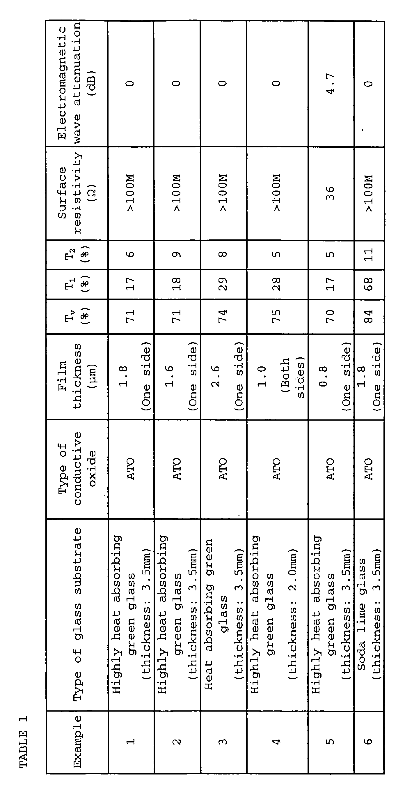
- the film thickness, the visible light transmittance, the infrared transmittance, the surface resistivity and the electromagnetic wave attenuation of the obtained infrared shielding glass were evaluated, and the results are shown in Table 1.
- the coating liquid E was applied by a spin coating method on one side of a highly heat absorbing green glass (T v : 76%, T 1 : 20%, T 2 : 47%) having a thickness of 3.5 mm, dried at 120°C for 5 minutes in the air atmosphere and then fired for 5 minutes in an electric furnace maintained at 660°C in the air atmosphere, to obtain an infrared shielding glass.
- the ratio of ATO:(silica + zirconia) of this infrared shielding film was the same as in the coating fluid E. Further, the average primary particle diameter of the fine particles of ATO in the formed infrared shielding film, was 10 nm.
- the film thickness, the visible light transmittance, the infrared transmittance, the surface resistivity and the electromagnetic wave attenuation, of the obtained infrared shielding glass was evaluated, and the results are shown in Table 1.
- An infrared shielding glass was obtained by treatment in the same manner as in Example 1 except that instead of using the highly heat absorbing green glass having a thickness of 3.5 mm, a heat absorbing green glass having a thickness of 3.5 mm (VFL, trade name, manufactured by Asahi Glass Company, Limited, T v : 81%, T 1 : 36%, T 2 : 61%) having a thickness of 3.5 mm was used.
- VFL trade name, manufactured by Asahi Glass Company, Limited
- the film thickness, the visible light transmittance, the infrared transmittance, the surface resistivity and the electromagnetic wave attenuation, of the obtained infrared shielding glass were evaluated, and the results are shown in Table 1.
- An infrared shielding glass was obtained by treatment in the same manner as in Example 1 except that instead of using the highly heat absorbing green glass having a thickness of 3.5 mm, a highly heat absorbing green glass (T v : 82%, T 1 : 39%, T 2 : 63%) having a thickness of 2.0 mm was used, and instead of on one side, on both sides of the glass substrate, the infrared shielding films having a thickness of 1.0 ⁇ m, were respectively formed.
- a coating liquid J 350 ml of 2-propanol, 125 ml of an aqueous solution containing 60% of stannic chloride, 5 g of antimony trichloride, 5 ml of methanol were mixed to obtain a coating liquid J.
- the coating liquid J was sprayed by a spray gun on one side of a highly heat absorbing green glass (T v : 76%, T 1 : 20%, T 2 : 47%) having a thickness of 3.5 mm preliminarily heated to 600°C, and then cooled to obtain an infrared shielding glass having an ATO film containing no matrix component formed on one side.
- the film thickness, the visible light transmittance, the infrared transmittance, the surface resistivity and the electromagnetic wave attenuation, of the obtained infrared shielding glass were evaluated, and the results are shown in Table 1.
- An infrared shielding glass was obtained by treatment in the same manner as in Example 1 except that instead of using the highly heat absorbing green glass having a thickness of 3.5 mm, a transparent soda lime glass (T v : 89%, T 1 : 79%, T 2 : 86%) having a thickness of 3.5 mm was used.
- the film thickness, the visible light transmittance, the infrared transmittance, the surface resistivity and the electromagnetic wave attenuation, of the obtained infrared shielding glass were evaluated, and the results are shown in Table 1.
- the infrared shielding glasses of Examples 1 to 4 are capable of effectively shielding infrared rays over the entire infrared region without lowering the surface resistivity and further capable of maintaining the visible light transmittance at a high level.
- Example 5 no matrix component is contained in the coating liquid, whereby the surface resistivity of the infrared shielding film is low, and the electromagnetic attenuation is large, such being undesirable as an infrared shielding glass of the present invention.
- Example 6 a transparent soda lime glass substrate is used as the glass substrate, whereby the infrared transmittance of the near infrared region (wavelength: from 0.8 to 1.5 ⁇ m) is particularly high, such being undesirable as an infrared shielding glass of the present invention.
- An aqueous solution containing 1 mass% of ammonia was dropwise added to an aqueous solution having tin chloride and indium chloride dissolved so that the molar ratio of tin/(indium + tin) would be 0.05 (metal concentration: 0.1 mol/liter), to coprecipitate indium hydroxide and tin hydroxide.
- Chloride ions, ammonium ions and water freed from the coprecipitate were removed by centrifugal separation, and the coprecipitate was fired at 600°C for two hours in the atmosphere to obtain an ITO powder having an average primary particle diameter of 30 nm.
- the obtained ITO powder 120 g was added to 280 g of deionized water having the pH adjusted 3 by nitric acid, followed by dispersion treatment by means of a wet system jet mill, to obtain a dispersion having fine particles of ITO dispersed.
- the average primary particle diameter of the fine particles of ITO in the obtained dispersion was 100 nm, and the solid content concentration in the obtained dispersion was 26 mass%.
- the obtained powder was put into pure water having a volume 100 times the volume of the powder, followed by filtration and washing to remove excess ammonium fluoride.
- the obtained powder was roughly pulverized in a mortar to obtain a fluorinated ITO powder.
- the fluorine concentration in the obtained fluorinated ITO powder was quantified as follows. Namely, sodium hydroxide was added to the fluorinated ITO powder, and the mixture was fused, cooled and then dissolved in pure water. The obtained solution was neutralized by an addition of hydrochloric acid and then, a citric acid ion intensified buffer solution having a 1.0 mol/liter sodium citrate aqueous solution adjusted with hydrochloric acid to pH 6, was added to prepare a liquid to be measured, whereupon the content of fluorine was measured by means of a fluorine ion electrode, and the ratio to the content of (ITO + fluorine) was obtained by calculation. The fluorine concentration in the fluorinated ITO powder was 1.8 mass%.
- Fine particles of ITO containing no fluorine were obtained in the same manner as for the dispersion A except that the 10 mass% ammonium fluoride aqueous solution was not added, and the step of filtering and washing the powder in pure water of 100 times by volume, was not carried out.
- UVFL highly heat absorbing green glass
- the film was dried at 120°C in the atmosphere for 5 minutes, and after the drying, an infrared shielding glass was obtained. T v , T 1 and T 2 of the obtained infrared shielding glass were measured.
- the infrared shielding film was scraped off and formed into a powder, and sodium hydroxide was added thereto.
- the mixture was fused, cooled and then dissolved in pure water.
- the obtained solution was neutralized by an addition of hydrochloric acid, and then, a citric acid ion intensified buffering solution having a 1.0 mol/liter sodium citrate aqueous solution adjusted with hydrochloric acid to pH 6, was added to obtain a liquid to be measured, whereupon the content of fluorine was measured by means of a fluorine ion electrode.
- the content of ITO was measured by an ICP method,-and the fluorine concentration was obtained by calculation.
- Example 8 The same treatment as in Example 8 was carried out except that instead of firing at 660°C in the atmosphere for 5 minutes, firing was carried out at 400°C in the atmosphere for 15 minutes, and the infrared shielding glass after the drying and after the firing was evaluated.
- the production conditions for the infrared shielding glass are shown in Table 2, the evaluation results of the infrared shielding glass after the drying and after the firing are shown in Table 3, and the results of evaluation of T v , T 1 and T 2 of the infrared shielding film are shown in Table 4.
- Example 8 The same treatment as in Example 8 was carried out except that instead of the combined use of 4 g of metyltrimethoxysilane and 0.5 g of tetramethoxysilane, 4.5 g of metyltrimethoxysilane was used alone, and the infrared shielding glass after the drying and after the firing was evaluated.
- the production conditions for the infrared shielding glass are shown in Table 2, the evaluation results of the infrared shielding glass after the drying and after the firing are shown in Table 3, and the results of evaluation of T v , T 1 and T 2 of the infrared shielding film are shown in Table 4.
- Example 8 The same treatment as in Example 8 was carried out except that instead of the combined use of 4 g of methyltrimethoxysilane and 0.5 g of tetramethoxysilane, 3 g of methyltrimethoxysilane and 1.5 g of tetramethoxysilane were used in combination, and the infrared shielding glass after the drying and the after the firing was evaluated.
- the production conditions for the infrared shielding glass are shown in Table 2
- the evaluation results of the infrared shielding glass after the drying and after the firing are shown in Table 3
- the results of evaluation of T v , T 1 and T 2 of the infrared shielding film are shown in Table 4.
- Example 8 The same treatment as in Example 8 was carried out except that instead of using the dispersion (liquid L), the dispersion (liquid M) (i.e. the dispersion of fine particles of ITO containing no fluorine) was used, and the infrared shielding glass after the drying and after the firing was evaluated.
- the production conditions for the infrared shielding glass are shown in Table 2, the evaluation results of the infrared shielding glass after the drying and after the firing are shown in Table 3, and the results of evaluation of T v , T 1 and T 2 of the infrared shielding film are shown in Table 4.
- Example 8 The same treatment as in Example 8 was carried out except that the firing at 660°C for 5 minutes in the atmosphere was not carried out, and the infrared shielding glass after the drying was evaluated.
- the production conditions for the infrared shielding glass are shown in Table 2, the evaluation results of the infrared shielding glass after the drying are shown in Table 3, and the results of evaluation of T v , T 1 and T 2 of the infrared shielding film are shown in Table 4.
- the infrared shielding glasses having a coating film containing fluorinated ITO particles in Examples 8 to 11 have infrared shielding properties and electromagnetic wave transmittance even after the heat treatment at a high temperature and have highly abrasion resistant coating films formed by firing at a high temperature and thus have high durability.
- XPS X-ray photoelectron spectrometry
- Example 12 contained particles of ITO containing no fluorine, whereby T 2 was remarkably increased by the firing at a high temperature, such being undesirable as an infrared shielding glass.
- Example 13 As a Comparative Example, the curing was carried out at a low temperature where no oxidation of ITO took place, whereby it had a high infrared shielding property and electromagnetic wave shielding property, but the durability of the coating film was low, such being undesirable.
- the infrared shielding glass of the present invention may be subjected to firing at a high temperature and has high durability, and thus it is useful even at a site where the coating film is exposed in the air. Further, it has a high electromagnetic wave transmittance, whereby in a case where an electromagnetic wave receiver and/or an electromagnetic wave transmitter (such as an antenna) is disposed in a room, electromagnetic waves to be received by the electromagnetic wave receiver or transmitted electromagnetic waves will not be attenuated, and in a case where an infrared shielding film is to be formed to cover a printed antenna of the printed antenna-coated glass, it is possible to prevent attenuation of the electromagnetic waves by the infrared shielding film, thereby to prevent decrease of the gain of the antenna.
- an electromagnetic wave receiver and/or an electromagnetic wave transmitter such as an antenna
- the infrared shielding glass of the present invention has a low infrared transmittance, is excellent in the heat insulation property and has a high visible light transmittance, and thus, it is useful as glass for automobile, glass for building, etc.
Landscapes
- Chemical & Material Sciences (AREA)
- Composite Materials (AREA)
- Life Sciences & Earth Sciences (AREA)
- Engineering & Computer Science (AREA)
- Chemical Kinetics & Catalysis (AREA)
- General Chemical & Material Sciences (AREA)
- Geochemistry & Mineralogy (AREA)
- Materials Engineering (AREA)
- Organic Chemistry (AREA)
- Inorganic Chemistry (AREA)
- Surface Treatment Of Glass (AREA)
- Paints Or Removers (AREA)
- Glass Compositions (AREA)
Abstract
Description


Claims (16)
- An infrared shielding glass comprising a glass substrate having at least one surface thereof coated with a coating liquid containing fine particles of conductive oxide and a matrix component to thereby provide an infrared shielding film, characterized in that the infrared shielding glass exhibits a transmittance at a wavelength of 1.0 µm of at most 35% and a transmittance at a wavelength of 2.0 µm of at most 20% and that the infrared shielding film has a surface resistivity of at least 1 MΩ/□.
- The infrared shielding glass according to Claim 1, which exhibits a visible light transmittance of at least 70% as prescribed in JIS R3106 (1998).
- The infrared shielding glass according to Claim 1 or 2, wherein the glass substrate exhibits a visible light transmittance of at least 70% as prescribed in JIS R3106 (1998), a transmittance at a wavelength of 1.0 µm of at most 45% and a transmittance at a wavelength of 2.0 µm of from 40 to 70%.
- The infrared shielding glass according to Claim 1 or 2, wherein the infrared shielding glass exhibits a transmittance at a wavelength of 1.0 µm of at most 25% and a transmittance at a wavelength of 2.0 µm of at most 15%.
- The infrared shielding glass according to Claim 4, wherein the glass substrate exhibits a visible light transmittance of at least 70% as prescribed in JIS R3106 (1998), a transmittance at a wavelength of 1.0 µm of at most 30% and a transmittance at a wavelength of 2.0 µm of from 40 to 50%.
- The infrared shielding glass according to any one of Claims 1 to 5, wherein the difference between the visible light transmittance of the infrared shielding glass and the visible light transmittance of the glass substrate is within 20%.
- The infrared shielding glass according to any one of Claims 1 to 6, wherein the fine particles of conductive oxide in the infrared shielding film has an average primary particle diameter of at most 100 nm.
- The infrared shielding glass according to any one of Claims 1 to 7, wherein the infrared shielding film has a film thickness of from 0.1 to 5.0 µm.
- The infrared shielding glass according to any one of Claims 1 to 8, wherein in the coating liquid, the fine particles of conductive oxide and the matrix component are contained in the ratio of the fine particles of conductive oxide : the matrix = 1:9 to 9:1 by mass ratio as calculated as oxides.
- The infrared shielding glass according to any one of Claims 1 to 9, wherein the fine particles of conductive oxide are at least one member selected from the group consisting of fine particles of ATO and fine particles of fluorinated ITO.
- The infrared shielding glass according to Claim 10, wherein the coating liquid contains fine particles of fluorinated ITO, and the fine particles of fluorinated ITO has a fluorine concentration of from 0.1 to 10 mass%.
- The infrared shielding glass according to Claim 10, wherein the infrared shielding film contains fine particles of fluorinated ITO, and the fine particles of fluorinated ITO has a fluorine concentration of from 0.05 to 10 mass%.
- The infrared shielding glass according to any one of Claims 1 to 12, which has a haze of at most 7% as measured by a haze meter prescribed in JIS R3212 (1998), after 1,000 rotations under a load of 4.9N by means of CF-10F abrasive wheel, in the Taber abrasion test as prescribed in JIS R3212 (1998).
- An infrared shielding glass comprising a glass substrate having at least one surface thereof coated with a coating liquid containing fine particles of conductive oxide and a matrix component to thereby provide an infrared shielding film, characterized in that the infrared shielding film exhibits a transmittance at a wavelength of 1.0 µm of at most 95% and a transmittance at a wavelength of 2.0 µm of at most 30% and has a surface resistivity of at least 1 MΩ/□.
- The infrared shielding glass according to Claim 14, wherein the infrared shielding film exhibits a visible light transmittance of at least 90% as prescribed in JIS R3106 (1998).
- A process for producing an infrared shielding glass as defined in any one of Claims 1 to 15, which comprises coating at least one surface of a glass substrate with a coating liquid containing fine particles of conductive oxide and a matrix component, followed by firing at from 350 to 750°C for from 1 to 60 minutes.
Applications Claiming Priority (3)
| Application Number | Priority Date | Filing Date | Title |
|---|---|---|---|
| JP2002219921 | 2002-07-29 | ||
| JP2002219921 | 2002-07-29 | ||
| PCT/JP2003/009587 WO2004011381A1 (en) | 2002-07-29 | 2003-07-29 | Infrared shielding glass |
Publications (2)
| Publication Number | Publication Date |
|---|---|
| EP1541536A1 true EP1541536A1 (en) | 2005-06-15 |
| EP1541536A4 EP1541536A4 (en) | 2007-04-11 |
Family
ID=31184744
Family Applications (1)
| Application Number | Title | Priority Date | Filing Date |
|---|---|---|---|
| EP03771402A Withdrawn EP1541536A4 (en) | 2002-07-29 | 2003-07-29 | ANTI-INFRARED SHIELD GLASS |
Country Status (5)
| Country | Link |
|---|---|
| US (1) | US20050164014A1 (en) |
| EP (1) | EP1541536A4 (en) |
| JP (1) | JP4470736B2 (en) |
| AU (1) | AU2003252287A1 (en) |
| WO (1) | WO2004011381A1 (en) |
Cited By (11)
| Publication number | Priority date | Publication date | Assignee | Title |
|---|---|---|---|---|
| EP1803601A1 (en) * | 2005-12-28 | 2007-07-04 | Nippon Sheet Glass Company Limited | Vehicle window glass and process for manufacturing the same |
| EP1862437A1 (en) * | 2006-05-30 | 2007-12-05 | Nippon Sheet Glass Company Limited | Transparent article with infrared shielding film |
| EP1736453A4 (en) * | 2004-03-31 | 2008-09-03 | Nippon Sheet Glass Co Ltd | Infrared cut glass |
| EP1870386A4 (en) * | 2005-04-15 | 2009-01-28 | Asahi Glass Co Ltd | GLASS PLATE WITH INFRARED SHIELD LAYER AND METHOD FOR MANUFACTURING THE SAME |
| US7749606B2 (en) | 2004-03-31 | 2010-07-06 | Nippon Sheet Glass Company, Limited | Article with organic-inorganic composite film and process for producing the same |
| US8039111B2 (en) | 2005-10-05 | 2011-10-18 | Nippon Sheet Glass Company, Limited | Article with organic-inorganic composite film |
| US8246848B2 (en) | 2005-11-15 | 2012-08-21 | Central Glass Company, Limited | Process for producing base material for forming heat shielding film |
| CN102775073A (en) * | 2012-07-09 | 2012-11-14 | 华尔润玻璃产业股份有限公司 | Process for producing heat-insulated glass by roller coating method |
| US8367187B2 (en) | 2005-12-28 | 2013-02-05 | Nippon Sheet Glass Company, Limited | Vehicle window pane and manufacturing method therefor |
| US8445096B2 (en) | 2006-01-17 | 2013-05-21 | Nippon Sheet Glass Company, Limited | Vehicle window glass and manufacturing method therefor |
| EP2036868A4 (en) * | 2006-09-08 | 2015-06-03 | Central Glass Co Ltd | Heat ray shielding glass for vehicle and process for producing the same |
Families Citing this family (12)
| Publication number | Priority date | Publication date | Assignee | Title |
|---|---|---|---|---|
| WO2007081045A1 (en) | 2006-01-16 | 2007-07-19 | Nippon Sheet Glass Company, Limited | Glass plate for thin-film formation |
| EP1842834A1 (en) * | 2006-04-04 | 2007-10-10 | Asahi Glass Company, Limited | Infrared shielding film-coated glass plate and process for its production |
| TWI533334B (en) * | 2007-11-02 | 2016-05-11 | Agc北美平面玻璃公司 | Transparent conductive oxide coating for thin film photovoltaic application and method of manufacturing the same |
| DE102009017547B4 (en) * | 2009-03-31 | 2022-06-09 | Schott Ag | Glass or glass-ceramic pane reflecting infrared radiation and method for the production thereof |
| WO2010143645A1 (en) * | 2009-06-12 | 2010-12-16 | 石原産業株式会社 | Near-infrared shielding coating agent curable at ordinary temperatures, near-infrared shielding film using same, and manufacturing method therefor |
| JP2012144217A (en) * | 2011-01-14 | 2012-08-02 | Asahi Glass Co Ltd | Automotive window glass |
| US20150175837A1 (en) * | 2013-12-23 | 2015-06-25 | Saint-Gobain Performance Plastics Corporation | Coating materials and low haze heat rejection composites |
| WO2015107904A1 (en) * | 2014-01-17 | 2015-07-23 | 日本板硝子株式会社 | Vehicle window glass and method for manufacturing same |
| JP2017014024A (en) * | 2015-06-26 | 2017-01-19 | 旭硝子株式会社 | Thermal barrier glass |
| TW201722704A (en) | 2015-10-15 | 2017-07-01 | 聖高拜塑膠製品公司 | Seasonal solar control composite |
| US10464840B2 (en) | 2016-10-05 | 2019-11-05 | Corning Incorporated | Near infrared shielding and laser-resistant window |
| WO2022107717A1 (en) * | 2020-11-18 | 2022-05-27 | Agc株式会社 | Glass substrate with thermal barrier film |
Family Cites Families (8)
| Publication number | Priority date | Publication date | Assignee | Title |
|---|---|---|---|---|
| US4069630A (en) * | 1976-03-31 | 1978-01-24 | Ppg Industries, Inc. | Heat reflecting window |
| KR100214428B1 (en) * | 1993-06-30 | 1999-08-02 | 후지무라 마사지카, 아키모토 유미 | Infrared ray shielding material and infrared ray shielding powder |
| JPH11343140A (en) * | 1998-05-28 | 1999-12-14 | Asahi Glass Co Ltd | Vehicle window glass |
| JP4096278B2 (en) * | 1998-12-10 | 2008-06-04 | 住友金属鉱山株式会社 | Solar shading film coating solution and solar shading film using the same |
| JP2000281387A (en) * | 1999-03-30 | 2000-10-10 | Nippon Sheet Glass Co Ltd | High heat-shielding and low radiation glass and glass article using the same |
| EP1188551B1 (en) * | 2000-09-14 | 2006-08-09 | Asahi Glass Co., Ltd. | Laminated glass |
| JP2002138271A (en) * | 2000-11-06 | 2002-05-14 | Sumitomo Metal Mining Co Ltd | Method for producing heat ray shielding fine particles and method for producing coating liquid for forming a heat ray shielding film using fine particles produced by this method |
| JP2003119023A (en) * | 2001-10-12 | 2003-04-23 | Mitsui Mining & Smelting Co Ltd | Method for producing ITO powder and ITO powder |
-
2003
- 2003-07-29 EP EP03771402A patent/EP1541536A4/en not_active Withdrawn
- 2003-07-29 AU AU2003252287A patent/AU2003252287A1/en not_active Abandoned
- 2003-07-29 WO PCT/JP2003/009587 patent/WO2004011381A1/en not_active Ceased
- 2003-07-29 JP JP2004524179A patent/JP4470736B2/en not_active Expired - Fee Related
-
2005
- 2005-01-27 US US11/043,170 patent/US20050164014A1/en not_active Abandoned
Cited By (14)
| Publication number | Priority date | Publication date | Assignee | Title |
|---|---|---|---|---|
| US7749606B2 (en) | 2004-03-31 | 2010-07-06 | Nippon Sheet Glass Company, Limited | Article with organic-inorganic composite film and process for producing the same |
| EP1736453A4 (en) * | 2004-03-31 | 2008-09-03 | Nippon Sheet Glass Co Ltd | Infrared cut glass |
| EP1870386A4 (en) * | 2005-04-15 | 2009-01-28 | Asahi Glass Co Ltd | GLASS PLATE WITH INFRARED SHIELD LAYER AND METHOD FOR MANUFACTURING THE SAME |
| US8039111B2 (en) | 2005-10-05 | 2011-10-18 | Nippon Sheet Glass Company, Limited | Article with organic-inorganic composite film |
| US8246848B2 (en) | 2005-11-15 | 2012-08-21 | Central Glass Company, Limited | Process for producing base material for forming heat shielding film |
| EP1949978A4 (en) * | 2005-11-15 | 2013-08-21 | Central Glass Co Ltd | Process for producing base material for forming heat shielding film |
| US7754335B2 (en) | 2005-12-28 | 2010-07-13 | Nippon Sheet Glass Company, Limited | Vehicle window glass and process for manufacturing the same |
| EP1803601A1 (en) * | 2005-12-28 | 2007-07-04 | Nippon Sheet Glass Company Limited | Vehicle window glass and process for manufacturing the same |
| US8367187B2 (en) | 2005-12-28 | 2013-02-05 | Nippon Sheet Glass Company, Limited | Vehicle window pane and manufacturing method therefor |
| CN101346318B (en) * | 2005-12-28 | 2013-02-13 | 日本板硝子株式会社 | Vehicle window glass and manufacturing method thereof |
| US8445096B2 (en) | 2006-01-17 | 2013-05-21 | Nippon Sheet Glass Company, Limited | Vehicle window glass and manufacturing method therefor |
| EP1862437A1 (en) * | 2006-05-30 | 2007-12-05 | Nippon Sheet Glass Company Limited | Transparent article with infrared shielding film |
| EP2036868A4 (en) * | 2006-09-08 | 2015-06-03 | Central Glass Co Ltd | Heat ray shielding glass for vehicle and process for producing the same |
| CN102775073A (en) * | 2012-07-09 | 2012-11-14 | 华尔润玻璃产业股份有限公司 | Process for producing heat-insulated glass by roller coating method |
Also Published As
| Publication number | Publication date |
|---|---|
| JPWO2004011381A1 (en) | 2005-11-24 |
| AU2003252287A1 (en) | 2004-02-16 |
| US20050164014A1 (en) | 2005-07-28 |
| EP1541536A4 (en) | 2007-04-11 |
| WO2004011381A1 (en) | 2004-02-05 |
| JP4470736B2 (en) | 2010-06-02 |
Similar Documents
| Publication | Publication Date | Title |
|---|---|---|
| US20050164014A1 (en) | Infrared shielding glass | |
| KR920002531B1 (en) | Picture display panel and the same | |
| US20080020134A1 (en) | Infrared shielding film-coated glass and process for its production | |
| US20110094416A1 (en) | Core-shell particles and method for producing core-shell particles | |
| EP2128091B1 (en) | Hollow microparticle, method for production thereof, coating composition, and article having coating film formed thereon | |
| EP1816109A1 (en) | Infrared shielding film-coated glass plate and process for its production | |
| US20080090073A1 (en) | Infrared shielding layer-coated glass plate and process for its production | |
| JP2002234754A (en) | Method for producing toughened functional film-coated glass article | |
| US7771831B2 (en) | Infrared shielding film-coated glass plate and process for its production | |
| Morimoto et al. | Wet chemical functional coatings for automotive glasses and cathode ray tubes | |
| EP1020891B1 (en) | Low-transmission transparent layered structure | |
| US12331171B2 (en) | Method for preparing a self-cleaning transparent thermal insulation nanocoating | |
| WO2007058016A1 (en) | Process for producing base material for forming heat shielding film | |
| JP2005194169A (en) | Glass with infrared shielding film and method for producing the same | |
| JP2005022941A (en) | Infrared shielding glass and manufacturing method thereof | |
| JP3399268B2 (en) | Transparent black conductive film | |
| JP3460484B2 (en) | Transparent conductive film | |
| JPH06144874A (en) | Heat ray reflective film and manufacturing method thereof | |
| AU2019267798A1 (en) | Surface-treated infrared-absorbing fine particle dispersion and infrared-absorbing transparent substrate | |
| JP3451808B2 (en) | Low reflective transparent conductive film and method for forming the same | |
| JP2006193670A (en) | Silica film-coated hexaboride fine particles, production method thereof, coating solution for optical member and optical member using the same | |
| WO2006112371A1 (en) | Heat insulating plate material for window | |
| JP2008169074A (en) | Insulating window plate | |
| JPWO2004046057A1 (en) | Thermal shielding plate, method for producing the same, and liquid composition used therefor | |
| JP2000203882A (en) | Coating solution for forming colored film, glass with colored film and method for producing the same |
Legal Events
| Date | Code | Title | Description |
|---|---|---|---|
| PUAI | Public reference made under article 153(3) epc to a published international application that has entered the european phase |
Free format text: ORIGINAL CODE: 0009012 |
|
| 17P | Request for examination filed |
Effective date: 20050127 |
|
| AK | Designated contracting states |
Kind code of ref document: A1 Designated state(s): AT BE BG CH CY CZ DE DK EE ES FI FR GB GR HU IE IT LI LU MC NL PT RO SE SI SK TR |
|
| AX | Request for extension of the european patent |
Extension state: AL LT LV MK |
|
| DAX | Request for extension of the european patent (deleted) | ||
| RBV | Designated contracting states (corrected) |
Designated state(s): BE DE FR GB |
|
| RIC1 | Information provided on ipc code assigned before grant |
Ipc: C03C 17/00 20060101AFI20070301BHEP |
|
| A4 | Supplementary search report drawn up and despatched |
Effective date: 20070312 |
|
| 17Q | First examination report despatched |
Effective date: 20070531 |
|
| STAA | Information on the status of an ep patent application or granted ep patent |
Free format text: STATUS: THE APPLICATION IS DEEMED TO BE WITHDRAWN |
|
| 18D | Application deemed to be withdrawn |
Effective date: 20100825 |