EP1541515A2 - Elevator with an all optical control apparatus - Google Patents
Elevator with an all optical control apparatus Download PDFInfo
- Publication number
- EP1541515A2 EP1541515A2 EP04106293A EP04106293A EP1541515A2 EP 1541515 A2 EP1541515 A2 EP 1541515A2 EP 04106293 A EP04106293 A EP 04106293A EP 04106293 A EP04106293 A EP 04106293A EP 1541515 A2 EP1541515 A2 EP 1541515A2
- Authority
- EP
- European Patent Office
- Prior art keywords
- fiber
- optical
- elevator
- light
- photodetector
- Prior art date
- Legal status (The legal status is an assumption and is not a legal conclusion. Google has not performed a legal analysis and makes no representation as to the accuracy of the status listed.)
- Withdrawn
Links
Images



Classifications
-
- B—PERFORMING OPERATIONS; TRANSPORTING
- B66—HOISTING; LIFTING; HAULING
- B66B—ELEVATORS; ESCALATORS OR MOVING WALKWAYS
- B66B1/00—Control systems of elevators in general
- B66B1/02—Control systems without regulation, i.e. without retroactive action
- B66B1/06—Control systems without regulation, i.e. without retroactive action electric
Definitions
- the present invention concerns an elevator having an optical system for initiating or triggering a function, such as a call for an elevator cabin.
- optical fibers are used to transmit information from a machine room control unit to an elevator display device, but these optical fibers have not fully replaced the electrical wiring and power lines required for power supply purposes and for signal transmission.
- the electrical supply is for example required to drive electronic information processing circuits and devices at the elevator landing area sites.
- certain elements at the elevator landing area sites and/or inside the elevator cabin require an electrical power supply. In consequence, the installation of these kind of elevator installations is tedious, costly and error prone.
- JP2002062387A discloses an elevator where a button is illuminated by a lamp that is spaced apart from the button in order to prevent the lamp from being destroyed by vibrations inside the button.
- the lamp is connected to the button by means of an optical fiber.
- a first apparatus is claimed in independent claim 1.
- This claim concerns an elevator with an all optical control apparatus.
- the control apparatus comprises a control unit with a light source, a photodetector, an optical feeding fiber, and an optical feedback fiber.
- the light source is coupled to the optical feeding fiber and the optical feedback fiber is coupled to the photodetector.
- the apparatus further comprises a member that can be manually actuated. The member is coupled to the optical feeding fiber and feedback fiber so that, when the member is actuated, a light path is influenced in a manner that is detectable at the photodetector.
- FIG. 1A is a schematic representation of an all optical control apparatus, according to a first embodiment of the present invention.
- FIG. 1B is a schematic representation of the all optical control apparatus of Fig. 1A after the member has been actuated
- FIG. 2A is a schematic representation of a first member, according the present invention.
- FIG. 2B is a schematic representation of the member of Fig. 2A after the member has been actuated
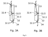
- FIG. 3A is a schematic representation of a second member, according the present invention.
- FIG. 3B is a schematic representation of the member of Fig. 3A after the member has been actuated
- FIG. 4A is a schematic representation of a third member, according the present invention.
- FIG. 4B is a schematic representation of the member of Fig. 4A after the member has been actuated
- FIG. 4C is a schematic front view of the member of Fig. 4A.
- FIG. 5 is a schematic representation of an all optical control indicator, according to a second embodiment of the present invention.
- FIG. 6 is a schematic representation of an all optical control indicator, according to a third embodiment of the present invention.
- an all optical control apparatus 10 is provided.
- a first embodiment is illustrated in Figures 1A and 1 B.
- "All optical" in the context of the present patent application means that no electrical wiring and no conversion from the optical to the electrical regime is required at a remote site.
- the all optical control apparatus 10 comprises a control unit 11 with a light source 16 and a photodetector 15.
- Well suited as light source 16 is a laser or a light emitting diode.
- Preferred embodiment employ one or more light emitting diodes, since these diodes are not as expensive as lasers and, even more important, are more robust.
- the apparatus 10 further comprises an optical feeding fiber 13 and an optical feedback fiber 14.
- the light source 16 is optically coupled to the optical feeding fiber 13 so that light (depicted by a flash symbol, for sake of simplicity) emitted by the light source 16 is coupled into the fiber 13 and guided through the fiber 13.
- a member 12 is provided that can be manually actuated. There are various ways to actuate the member, as will be discussed in connection with different embodiments.
- the word “actuate” not necessarily means that a mechanical movement is caused.
- the word “actuate” in the present context is also meant to cover non-mechanical activities.
- the member 12 comprises a fiber input 12.1 and a fiber output 12.2.
- the fibers 13, 14 may be attached, linked or coupled to said input 12.1 and output 12.2 to provide an optical coupling that allows light to be coupled from the fiber 13 into the member 12 and from the member 12 into the fiber 14.
- the feedback fiber 14 is optically coupled to the photodetector 15, as schematically illustrated in Fig. 1A and Fig. 1 B.
- the member 12, when actuated influences a light path 12.3 between the fiber input 12.1 and the fiber output 12.2 in a manner that is detectable at the photodetector 15.
- Fig. 1A a state is shown, where light is emitted by a diode 16, guided through the fiber 13 to the member 12, and from the member 12 through the fiber 14 back to the photodetector 15.
- a closed optical loop is provided and the photodetector generates an electrical signal (photo current) that can be processed by some electrical circuitry not shown in the Figures.
- the member 12 is actuated, as schematically illustrated in Fig. 1B, the light path 12.3 is influenced, in which case the electrical signal provided by the photodetector 15 is reduces, or the light path 12.3 is interrupted in which case the electrical signal may go down to zero.
- the later case is illustrated an no light reaches the photodetector 15.
- the electrical circuitry is now able to detect this change in light intensity and an action or reaction can be caused.
- the apparatus 10 may be coupled to an electrical elevator control 9, as shown in Figures 1A and 1B.
- a first embodiment of a member 22 is schematically illustrated in Figures 2A and 2B.
- the member 22 can be manually actuated by pressing a button 22.4, as indicated in the Figures by means of arrows.
- the member 22 comprises a fiber input 22.1 and a fiber output 22.2.
- the fibers 23, 24 may be attached, linked or coupled to said input 22.1 and output 22.2 to provide an optical coupling that allows light to be coupled from the fiber 23 into the member 22 and from the member 22 into the fiber 24.
- Fig. 2A a state is shown, where a light path 22.3 exists between the input 22.1 and output 22.2. If the button 22.4 is pushed, a portion of it moves into the light path 22.3 and influences or even interrupts the light path, as shown in Fig. 2B. In this case, light with reduced intensity or no light is provided at the output side 22.2. This is detectable at the control unit's photodetector 15.
- the button 22.4 may be guided or mounted so that it springs back after it was pushed. In this case, the actuation leads to a temporary influence or interrupt of the light path 22.3.
- a second embodiment of a member 32 is schematically illustrated in Figures 3A and 3B.
- the member 32 can be manually actuated by pressing a button 32.4, as indicated in the Figures by means of arrows.
- the member 32 comprises a fiber input 32.1 and a fiber output 32.2.
- the fibers 33, 34 may be attached, linked or coupled to said input 32.1 and output 32.2 to provide an optical coupling that allows light to be coupled from the fiber 33 into the member 32 and from the member 32 into the fiber 34.
- a flexible fiber element 32.3 is provided inside the member 32.
- a spring 32.5 is arranged to push the flexible fiber 32.3 in a position where no light is coupled from the flexible fiber 32.3 into the fiber 34. If the button 32.4 is pushed down, as illustrated in Fig.
- the fiber 32.3 is moved in a position where light is coupled from the fiber 32.3 into the fiber 34.
- the optical loop is closed and the control unit's photodetector 15 receives light through the fiber 34.
- the light is only coupled into the fiber 34 as long as the button 32.4 is pushed. If the button 32.4 is released, the spring moves the flexible fiber 32.3 and the button 32.4 back into the original position.
- a third embodiment of a member 42 is schematically illustrated in Figures 4A, 4B and 4C.
- the member 42 can be manually actuated by moving a finger F, as indicated in Fig. 4B, into a recess of the member 42.
- the member 42 comprises a fiber input 42.1 and a fiber output 42.2.
- the fibers 43, 44 may be attached, linked or coupled to said input 42.1 and output 42.2 to provide an optical coupling that allows light to be coupled from the fiber 43 into the member 42 and from the member 42 into the fiber 44.
- a light path 42.3 is provided between the input 42.1 and output 42.2, as illustrated in Fig. 4A.
- the member 42 may be integrated into a panel 45.
- the panel 45 may further comprise an all optical indicator 46, as will be discussed in connection with subsequent Figures.
- the member 42 functions like a touch sensitive button.
- the all optical control apparatus allows all electrical functions to be realized in an area, e.g. in a control room or machine room of the elevator, that is remote from the location where the member is reachable by a user of the elevator. From this area, only two fibers, the feeding fiber and the feedback fiber, are required to enable the user to do any of the following:
- the members can be realized so that,
- buttons or fingers instead of using a button or finger, one can also use a key or another element that is able to influence the light path.
- the all optical control apparatus serves as a fiber-based remote control.
- the all optical control apparatus can be expanded to also include an all optical indicator.
- almost all elevator control panels require some kind of optical indicator 46 in order to give some feedback after a button was pressed, or to announce that an elevator cabin is about to arrive, for example.
- Indicators may also be used to indicate a certain state or position of the cabin, to inform the passengers that an overload situation has occurred, that a cabin is to be evacuated, and so forth.
- the no electrical cabling is required to realize an optical indicator. Two embodiments will be discussed in connection with Figures 5 and 6.
- An all optical indicator 50 comprises light sources 55, 56 at a control unit 51, optical supply fibers 53, 54 connected to the light sources 55, 56, and an optical element 52.
- the optical element comprises two fiber segments 52.1 and 52.2, that each have the form of a triangle.
- the fiber segment 52.1 forms a triangle that points upwards and the fiber segment 52.2 forms a triangle that points downwards.
- the indicator 50 may be used to indicate the current traveling direction of the cabin by illuminating the respective triangle. If the cabin moves upwards, the light source 56 is activated an light is optical coupled into the supply fiber 53. This fiber 53 guides the light from the light source 55 to the fiber segment 52.1.
- the fiber segment 52.1 allows light to escape the fiber as if the triangle would emit light. Due to this, an upwards pointing triangle becomes visible. If the cabin moves downwards, the light source 55 is activated and the triangle 52.2 starts to "emit" light.
- the optical element 52 may be part of a panel or plate that is situated at a landing floor or inside the elevator cabin.
- diffusing elements 57 may be situated on top, as illustrated in Fig. 5 by means of dashed lines.
- the diffusing element not only provides for a diffusion of the light that escapes the fiber segments underneath, but it also can be used.
- Another all optical indicator 60 comprises a light source, an optical supply fiber 63 connected to the light source, and an optical element 62.
- the optical element comprises one fiber segment 62.1, that has the form of a circle. If a user has called an elevator cabin, the indicator 60 may be used to indicate that a call was placed by activating the light source. The light will be guide through the fiber 63 to the fiber segment 62.1 where at least some of the light escapes the fiber. Due to this, a circle becomes visible.
- the fiber segment 62.1 may be situated behind a transparent shield.
- the all optical indicators may be employed.
- the all optical control indicators serve as a remotely, optically driven display indicating a state (e.g., traveling direction, call registered, confirmation signal etc.) of the elevator.
- bare plastic fiber segments preferably a PMMA fiber segments.
- a fiber called Poly Bright TM or any other kind of side light fiber that allows light to escape.
- the fiber may be structured. If one applies cuts or if the fiber has a roughened surface, some of the light is deflected out of the fiber core. Those parts of the fiber segments that are not supposed to emit light can be covered by a resin or can be put in a thin hose or tube-shaped element.
- the fiber segments may be used without any protective shield or without any diffusing element if the fiber segments themselves are protected against mechanical damage.
- a protective coating or cladding may be applied. Such a coating also may protect the fiber segments against fire. Fiber segments with coating or cladding can be embedded in walls, cement or concrete directly.
- optical fibers that are being situated between the remote area where the control unit is placed and the location where the user has access to the member or where the indicator is visible may be protected by means of a coating or cladding as well.
- the optical fibers may be clad in a PVC covering, for example. This is recommended if the fibers are applied without any protective tubing.
- Fiber connectors may be used for easier installation and maintenance. Such connectors allow two optical fibers to be connected and, if needed, to be disconnected again.
- One light source may for example be used to feed light via one common fiber to a member for calling a cabin and to an indicator associated with this member.
- One light source may for example be used to feed light via one common fiber to a member for calling a cabin and to an indicator associated with this member.
- One light source may for example be used to feed light via one common fiber to a member for calling a cabin and to an indicator associated with this member.
- Such an embodiment would allow a push button to be realized that in its normal state is dark. If somebody pushed the button to call a cabin, the light path to the photodetector is interrupted temporarily and the light is guided into a fiber segment, like the one in Fig. 6, instead. That is, as long as the button is pushed, the button emits light. This gives the user a confirmation that the button was pushed hard enough. If the button is released, the light path is re-established and the button stops to emit light.
- control unit is located in or near to the elevator's machine room.
- the corresponding supplier and logic is placed at the control unit.
- the control unit may be connected to the electrical elevator control 9, as indicated in Figures 1A, 1 B, and 5.
- the light source is located at or close to the machine room where an electrical power supply is easily available. It is also more easy to replace defective elements, since all sensitive elements, such as the light sources are placed at one and the same location. One does not have to visit floor by floor to check and replace broken lamps, like in conventional systems.
- the present invention enables solutions that are appealing from an aesthetic point of view.
- the respective panels at the landing floors and inside the cabin can be slimmer, for example.
- control unit can be placed in a rack or room that is fire proof. Since the fibers are able to withstand heat and fire better than most electrical cabling, this allows to realize elevators that provide certain basic function even in case of fire.
Landscapes
- Engineering & Computer Science (AREA)
- Automation & Control Theory (AREA)
- Indicating And Signalling Devices For Elevators (AREA)
- Maintenance And Inspection Apparatuses For Elevators (AREA)
Abstract
Description
- to register a call for an elevator cabin, or
- to register a destination floor, or
- to register an emergency call.
- when actuated they interrupt a light path so that no light or light with reduced intensity is received at the photodetector, or
- when actuated they connect/establish/improve a light path so that light is received at the photodetector.
- to indicate that a call for an elevator cabin is registered, or
- to indicate that a destination floor is registered, or
- to indicate the traveling direction of the elevator cabin, or
- to indicate that an emergency call is registered, just to give some examples.
Claims (9)
- Elevator with an all optical control apparatus (10)comprising a control unit (11) with a light source (16), a photodetector (15), an optical feeding fiber (13; 23; 33; 43), an optical feedback fiber (14; 24; 34; 44), said light source (16) being optically coupled to said optical feeding fiber (13; 23; 33; 43), and said optical feedback fiber (14; 24; 34; 44) being optically coupled to said photodetector (15), a member (12; 22; 32; 42) that can be manually actuated, said member (12; 22; 32; 42) comprising a fiber input (12.1; 22.1; 32.1; 42.1) and a fiber output (12.2; 22.2; 32.2; 42.2), said fiber input (12.1; 22.1; 32.1; 42.1) being optically coupled to said optical feeding fiber (13; 23; 33; 43) and said fiber output (12.2; 22.2; 32.2; 42.2) being optically coupled to said optical feedback fiber (14; 24; 34; 44), wherein said member (12; 22; 32; 42), when actuated, influences a light path (12.3; 22.3; 32.3; 42.3) between said fiber input (12.1; 22.1; 32.1; 42.1) and said fiber output (12.2; 22.2; 32.2; 42.2) in a manner that is detectable at the photodetector (15).
- The elevator of claim 1, wherein said member (22; 32) comprises a push button (22.4; 32.4) or key that, when actuated interrupts the light path (22.3) so that no light is receivable at the photodetector anymore, or that when actuated connects the light path (32.3) so that light is receivable at the photodetector.
- The elevator of claim 1 or 2, wherein an electrical output signal provided by said photodetector is used to register a call for an elevator cabin, or to register a destination floor, or to register an emergency call.
- The elevator of one of the claims 1 through 3, further comprising an all optical indicator (50; 60) with a light source (55, 56) at the control unit (51), an optical supply fiber (53, 54; 63) connectable to said light source (55, 56), an optical element (52; 62), said optical supply fiber (53, 54; 63) guiding light from said light source (55, 56) to said optical element (52; 62) such that light becomes visible when being coupled at said control unit (51) into said optical supply fiber (53, 54; 63).
- The elevator of claim 4, wherein the all optical indicator (50; 60) is employed to indicate that a call for an elevator cabin is registered, or to indicate that a destination floor is registered, or to indicate the traveling direction of the elevator cabin, or to indicate that an emergency call is registered.
- The elevator of one of the claims 1 through 3, wherein said member (12; 22; 32; 42) is located at a landing floor or inside an elevator cabin.
- The elevator of one of the claims 4 or 5, wherein said all optical indicator (50; 60) is located at a landing floor or inside an elevator cabin.
- The elevator of one of the claims 4 or 5, wherein said optical element (52; 62) comprises a plastic fiber, preferably a PMMA fiber.
- The elevator of one of the preceding claims, wherein said control unit (11; 51) is connectable to an electrical elevator control (9).
Priority Applications (1)
| Application Number | Priority Date | Filing Date | Title |
|---|---|---|---|
| EP04106293A EP1541515A3 (en) | 2003-12-08 | 2004-12-03 | Elevator with an all optical control apparatus |
Applications Claiming Priority (3)
| Application Number | Priority Date | Filing Date | Title |
|---|---|---|---|
| EP03405876 | 2003-12-08 | ||
| EP03405876 | 2003-12-08 | ||
| EP04106293A EP1541515A3 (en) | 2003-12-08 | 2004-12-03 | Elevator with an all optical control apparatus |
Publications (2)
| Publication Number | Publication Date |
|---|---|
| EP1541515A2 true EP1541515A2 (en) | 2005-06-15 |
| EP1541515A3 EP1541515A3 (en) | 2009-10-28 |
Family
ID=34524779
Family Applications (1)
| Application Number | Title | Priority Date | Filing Date |
|---|---|---|---|
| EP04106293A Withdrawn EP1541515A3 (en) | 2003-12-08 | 2004-12-03 | Elevator with an all optical control apparatus |
Country Status (1)
| Country | Link |
|---|---|
| EP (1) | EP1541515A3 (en) |
Family Cites Families (6)
| Publication number | Priority date | Publication date | Assignee | Title |
|---|---|---|---|---|
| US4623869A (en) * | 1983-07-22 | 1986-11-18 | Mitsubishi Denki Kabushiki Kaisha | Elevator display system with optical power transmission |
| JP3628356B2 (en) * | 1993-09-29 | 2005-03-09 | オーチス エレベータ カンパニー | Elevator car position detector |
| JPH08169655A (en) * | 1994-12-19 | 1996-07-02 | Sumitomo Electric Ind Ltd | Optical fiber wiring system for elevator monitoring control |
| US5950767A (en) * | 1997-08-15 | 1999-09-14 | Otis Elevator Company | Optical door lock |
| FR2775272A1 (en) * | 1998-02-25 | 1999-08-27 | Otis Elevator Co | Optical security system for lifts which does not need potentially dangerous electric circuits or space for cable troughs. The system has a long life and is light and compact. |
| JP2002348067A (en) * | 2001-05-22 | 2002-12-04 | Hitachi Ltd | Elevator equipment |
-
2004
- 2004-12-03 EP EP04106293A patent/EP1541515A3/en not_active Withdrawn
Also Published As
| Publication number | Publication date |
|---|---|
| EP1541515A3 (en) | 2009-10-28 |
Similar Documents
| Publication | Publication Date | Title |
|---|---|---|
| JP5902995B2 (en) | Moving system using LED tube, moving method, and LED tube | |
| US4805739A (en) | Elevator control switch and position indicator assembly | |
| US9103931B2 (en) | Modular light curtain and optical unit for a light curtain | |
| US20120041593A1 (en) | Elevator system that autonomous mobile robot takes together with person | |
| US7380641B2 (en) | Elevator with a control using optical fibers | |
| CN113825715A (en) | Elevator system and method for modifying elevator | |
| US20090295550A1 (en) | Elevator system with wireless hall call buttons | |
| US12509325B2 (en) | Elevator system with touchless elevator call entry | |
| WO2004076915A1 (en) | Escape way direction system | |
| HK1079174A (en) | Elevator with an all optical control apparatus | |
| KR102544753B1 (en) | Elevator system and how to repair the elevator | |
| CN111326085B (en) | Illuminable display device | |
| KR102560280B1 (en) | Elevator operation display device | |
| EP4161216A1 (en) | Lighting driver with remote indicator led and emergency test button | |
| KR101069694B1 (en) | Multi-post operation escalator and maving walk head sensor turn round an angle reguiation | |
| JPH05333226A (en) | Optical module drive controller | |
| CN112888646B (en) | Operating button of elevator and operating panel of elevator | |
| US4951787A (en) | Elevator control and indicator device | |
| CN112840426B (en) | Elevator operating buttons and elevator operating panel | |
| JP2007055797A (en) | Car operation panel power source device for elevator | |
| CN117724183A (en) | Light curtain | |
| KR870001134Y1 (en) | Elevator floor display device using optical fiber | |
| CN202310307U (en) | Attaching device and prompt circuit | |
| JPH1154001A (en) | Light detecting system and visually confirming device | |
| KR19980078286A (en) | Emergency exit marking method and the emergency exit indicator |
Legal Events
| Date | Code | Title | Description |
|---|---|---|---|
| PUAI | Public reference made under article 153(3) epc to a published international application that has entered the european phase |
Free format text: ORIGINAL CODE: 0009012 |
|
| AK | Designated contracting states |
Kind code of ref document: A2 Designated state(s): AT BE BG CH CY CZ DE DK EE ES FI FR GB GR HU IE IS IT LI LT LU MC NL PL PT RO SE SI SK TR |
|
| AX | Request for extension of the european patent |
Extension state: AL BA HR LV MK YU |
|
| REG | Reference to a national code |
Ref country code: HK Ref legal event code: DE Ref document number: 1079174 Country of ref document: HK |
|
| PUAL | Search report despatched |
Free format text: ORIGINAL CODE: 0009013 |
|
| AK | Designated contracting states |
Kind code of ref document: A3 Designated state(s): AT BE BG CH CY CZ DE DK EE ES FI FR GB GR HU IE IS IT LI LT LU MC NL PL PT RO SE SI SK TR |
|
| AX | Request for extension of the european patent |
Extension state: AL BA HR LV MK YU |
|
| RIC1 | Information provided on ipc code assigned before grant |
Ipc: B66B 1/06 20060101ALI20090923BHEP Ipc: B66B 3/00 20060101AFI20090923BHEP |
|
| AKX | Designation fees paid | ||
| REG | Reference to a national code |
Ref country code: DE Ref legal event code: 8566 |
|
| STAA | Information on the status of an ep patent application or granted ep patent |
Free format text: STATUS: THE APPLICATION IS DEEMED TO BE WITHDRAWN |
|
| 18D | Application deemed to be withdrawn |
Effective date: 20100428 |
|
| REG | Reference to a national code |
Ref country code: HK Ref legal event code: WD Ref document number: 1079174 Country of ref document: HK |