EP1541468A1 - Aircraft turbofan engine mounting - Google Patents
Aircraft turbofan engine mounting Download PDFInfo
- Publication number
- EP1541468A1 EP1541468A1 EP04257025A EP04257025A EP1541468A1 EP 1541468 A1 EP1541468 A1 EP 1541468A1 EP 04257025 A EP04257025 A EP 04257025A EP 04257025 A EP04257025 A EP 04257025A EP 1541468 A1 EP1541468 A1 EP 1541468A1
- Authority
- EP
- European Patent Office
- Prior art keywords
- bypass duct
- engine
- arrangement
- assembly
- structural bypass
- Prior art date
- Legal status (The legal status is an assumption and is not a legal conclusion. Google has not performed a legal analysis and makes no representation as to the accuracy of the status listed.)
- Granted
Links
- 230000000712 assembly Effects 0.000 claims description 14
- 238000000429 assembly Methods 0.000 claims description 14
- 230000006835 compression Effects 0.000 abstract 1
- 238000007906 compression Methods 0.000 abstract 1
- 230000001627 detrimental effect Effects 0.000 description 2
- 230000033001 locomotion Effects 0.000 description 2
- 230000005540 biological transmission Effects 0.000 description 1
- 238000010276 construction Methods 0.000 description 1
- 230000004048 modification Effects 0.000 description 1
- 238000012986 modification Methods 0.000 description 1
Images


Classifications
-
- B—PERFORMING OPERATIONS; TRANSPORTING
- B64—AIRCRAFT; AVIATION; COSMONAUTICS
- B64D—EQUIPMENT FOR FITTING IN OR TO AIRCRAFT; FLIGHT SUITS; PARACHUTES; ARRANGEMENT OR MOUNTING OF POWER PLANTS OR PROPULSION TRANSMISSIONS IN AIRCRAFT
- B64D27/00—Arrangement or mounting of power plants in aircraft; Aircraft characterised by the type or position of power plants
- B64D27/40—Arrangements for mounting power plants in aircraft
- B64D27/402—Arrangements for mounting power plants in aircraft comprising box like supporting frames, e.g. pylons or arrangements for embracing the power plant
-
- F—MECHANICAL ENGINEERING; LIGHTING; HEATING; WEAPONS; BLASTING
- F02—COMBUSTION ENGINES; HOT-GAS OR COMBUSTION-PRODUCT ENGINE PLANTS
- F02C—GAS-TURBINE PLANTS; AIR INTAKES FOR JET-PROPULSION PLANTS; CONTROLLING FUEL SUPPLY IN AIR-BREATHING JET-PROPULSION PLANTS
- F02C7/00—Features, components parts, details or accessories, not provided for in, or of interest apart form groups F02C1/00 - F02C6/00; Air intakes for jet-propulsion plants
- F02C7/20—Mounting or supporting of plant; Accommodating heat expansion or creep
Definitions
- This invention concerns aircraft engine mounting assemblies, and also gas turbine aircraft engines incorporating such assemblies.
- the nacelle In high speed aircraft applications it is considered desirable on the engines for the nacelle to be wrapped tightly to the engine case to reduce the drag caused by the nacelle. This can mean that the space to fit a conventional engine mounting between the outer engine duct, i.e. structural bypass duct, and the nacelle is very limited.
- an aircraft engine mounting assembly including a pair of inclined links extending from spaced locations on the engine core casing to a bracket arrangement located on the structural bypass duct, the bracket arrangement being configured such that in normal operation said arrangement does not substantially engage with the structural bypass duct and transmits engine loads directly into the airframe, but upon a failure of part of the engine mounting the bracket arrangement will engage with the structural bypass duct to transmit engine loads into the airframe via the structural bypass duct.
- the bracket arrangement preferably locates in an opening in the structural bypass duct.
- the bracket arrangement preferably includes a first part located on the exterior of the structural bypass duct and overlapping the structural bypass duct around the opening.
- the bracket arrangement may also include a second part located on the interior of the structural bypass duct and overlapping the structural bypass duct around the opening.
- the mounting assembly is preferably arranged such that the first and second parts substantially only transmit loads to the structural bypass duct following a failure of part of the engine mounting.
- Seals may be provided between the first part and the structural bypass duct, and/or the second part and the structural bypass duct.
- the first and/or second parts may be in the form of plates.
- a body may extend between the first and second parts, which body mounts the respective ends of the links.
- a seal may be provided around the body and engageable with the edge of the opening in the structural bypass duct.
- the first part may be releasably mounted on the body whereby to facilitate engine removal.
- the assembly is preferably provided towards the rear of the engine.
- the invention also provides a gas turbine engine mounting arrangement, the arrangement including at least one assembly according to any of the preceding six paragraphs.
- the gas turbine engine mounting arrangement may also include a plurality of link assemblies extending between the engine core casing and the structural bypass duct.
- the link assemblies and the mounting assemblies may be substantially equispaced around the engine, and three link assemblies and one mounting assembly may be provided.
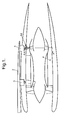
- Fig. 1 shows the mounting of a gas turbine engine 1 under a wing 2 of an aircraft.
- a front mounting plane 3 and a rear mounting plane 4 are provided.
- Fig. 2 illustrates the rear mounting plane 4 with the engine core casing in the form of a tail bearing housing 10 being mounted to and spaced from the structural bypass duct 12 by three link assemblies 5 and an engine mounting assembly 14 according to the invention.
- the assemblies 5, 14 are equispaced around the housing 10, with the assembly 14 immediately beneath the wing 2.
- Fig. 3 shows the engine mounting assembly 14 including a bracket arrangement 16 which locates in an opening 18 provided in the duct 12.
- the arrangement 16 comprises a first part in the form of an exterior plate 20 which is located on the exterior of the duct 12 so as to overlap the edges of the opening 18.
- a second part in the form of an interior plate 22 is provided on the interior of the duct 12 again overlapping the edges of the opening 18.
- the arrangement 16 also comprises a body 24 extending between the plates 20,22 through the opening 18 and a little below the interior plate 22.
- a seal 26 is provided between the body 24 and the edge of the opening 18. Further seals 28 are provided between the plates 20,22 adjacent their perimeter and the duct 12.
- Bolts 30 around the exterior plate 20 to the body 24 are removable to readily permit removal of the engine.
- a pair of links 30 extend from the body 24 in an A-frame arrangement to spaced locations on the tail bearing housing 10.
- the links 30 are mounted so as to permit movement relative to the housing 10 and body 24.
- the opening 18 provides sufficient clearance for relative motions due to thermal growth or load induced deflections during normal operation.
- the load would then be transmitted at least in part onto the duct 12, by virtue of engagement of the plates 20,22 on the duct 12 around the opening 18.
- the bypass duct 12 is kept concentric to the engine core casing by means of the link assemblies 5 such that in the event of an engine mounting failure such as a failed link, any engine loads are passed via the link assemblies 5 into the structural bypass duct 12, and then via the body 24 to the airframe.
- the body 24 could be utilised as a failsafe catcher for engine thrust loads, whether or not the remainder of the rear mounting plane 4 is in its usual unfailed condition.
Landscapes
- Engineering & Computer Science (AREA)
- Chemical & Material Sciences (AREA)
- Combustion & Propulsion (AREA)
- Aviation & Aerospace Engineering (AREA)
- Mechanical Engineering (AREA)
- General Engineering & Computer Science (AREA)
- Structures Of Non-Positive Displacement Pumps (AREA)
Abstract
Description
- This invention concerns aircraft engine mounting assemblies, and also gas turbine aircraft engines incorporating such assemblies.
- In high speed aircraft applications it is considered desirable on the engines for the nacelle to be wrapped tightly to the engine case to reduce the drag caused by the nacelle. This can mean that the space to fit a conventional engine mounting between the outer engine duct, i.e. structural bypass duct, and the nacelle is very limited.
- With engine mountings it is desirable to provide a "failsafe" arrangement to permit continued operation in the event of a part of the engine mounting failing in use. Such an arrangement should though have little or no detrimental effect on the engine's performance. One proposal has been to provide an additional link which only becomes load bearing upon the failure of another link. Such an additional link however tends to increase blockage and drag, and thus is detrimental to the engine's performance.
- According to the present invention there is provided an aircraft engine mounting assembly, the assembly including a pair of inclined links extending from spaced locations on the engine core casing to a bracket arrangement located on the structural bypass duct, the bracket arrangement being configured such that in normal operation said arrangement does not substantially engage with the structural bypass duct and transmits engine loads directly into the airframe, but upon a failure of part of the engine mounting the bracket arrangement will engage with the structural bypass duct to transmit engine loads into the airframe via the structural bypass duct.
- The bracket arrangement preferably locates in an opening in the structural bypass duct. The bracket arrangement preferably includes a first part located on the exterior of the structural bypass duct and overlapping the structural bypass duct around the opening. The bracket arrangement may also include a second part located on the interior of the structural bypass duct and overlapping the structural bypass duct around the opening. The mounting assembly is preferably arranged such that the first and second parts substantially only transmit loads to the structural bypass duct following a failure of part of the engine mounting.
- Seals may be provided between the first part and the structural bypass duct, and/or the second part and the structural bypass duct.
- The first and/or second parts may be in the form of plates. A body may extend between the first and second parts, which body mounts the respective ends of the links. A seal may be provided around the body and engageable with the edge of the opening in the structural bypass duct.
- The first part may be releasably mounted on the body whereby to facilitate engine removal.
- The assembly is preferably provided towards the rear of the engine.
- The invention also provides a gas turbine engine mounting arrangement, the arrangement including at least one assembly according to any of the preceding six paragraphs.
- The gas turbine engine mounting arrangement may also include a plurality of link assemblies extending between the engine core casing and the structural bypass duct. The link assemblies and the mounting assemblies may be substantially equispaced around the engine, and three link assemblies and one mounting assembly may be provided.
- An embodiment of the present invention will now be described by way of example only and with reference to the accompanying drawings, in which:-
- Fig. 1 is a diagrammatic sectional side view of part of an aircraft showing mounting of a gas turbine engine on the aircraft;
- Fig. 2 is a schematic sectional view on the line A-A of Fig. 1; and
- Fig. 3 is a diagrammatic view in a similar direction to Fig. 2 of a part of the aircraft of Fig. 1.
-
- Fig. 1 shows the mounting of a gas turbine engine 1 under a wing 2 of an aircraft. A front mounting plane 3 and a
rear mounting plane 4 are provided. Fig. 2 illustrates therear mounting plane 4 with the engine core casing in the form of atail bearing housing 10 being mounted to and spaced from thestructural bypass duct 12 by threelink assemblies 5 and anengine mounting assembly 14 according to the invention. Theassemblies housing 10, with theassembly 14 immediately beneath the wing 2. - Fig. 3 shows the
engine mounting assembly 14 including abracket arrangement 16 which locates in anopening 18 provided in theduct 12. Thearrangement 16 comprises a first part in the form of anexterior plate 20 which is located on the exterior of theduct 12 so as to overlap the edges of theopening 18. A second part in the form of aninterior plate 22 is provided on the interior of theduct 12 again overlapping the edges of theopening 18. Thearrangement 16 also comprises abody 24 extending between theplates interior plate 22. Aseal 26 is provided between thebody 24 and the edge of the opening 18.Further seals 28 are provided between theplates duct 12.Bolts 30 around theexterior plate 20 to thebody 24 are removable to readily permit removal of the engine. - A pair of
links 30 extend from thebody 24 in an A-frame arrangement to spaced locations on thetail bearing housing 10. Thelinks 30 are mounted so as to permit movement relative to thehousing 10 andbody 24. The opening 18 provides sufficient clearance for relative motions due to thermal growth or load induced deflections during normal operation. - In normal usage, engine loads, whether side or vertical loads, would be carried by the
links 30 to thebody 24, and thebody 24 would interface with the airframe (not shown). Theplates duct 12, and theseals duct 12. - In the event of a failure of the engine mounting such as for example one of the
links 30, whether within its length or at one of its mountings, the load would then be transmitted at least in part onto theduct 12, by virtue of engagement of theplates duct 12 around the opening 18. - Vertical loads are reacted via the
plates body 24 with shoulders in theopening 18. Axial clearance between thebody 24 and the opening 18 requires to be sufficient to avoid transmission of thrust loads in this failure case. - The
bypass duct 12 is kept concentric to the engine core casing by means of the link assemblies 5 such that in the event of an engine mounting failure such as a failed link, any engine loads are passed via thelink assemblies 5 into thestructural bypass duct 12, and then via thebody 24 to the airframe. - Also, in the event of failure of the engine mounting such as any thrust link for example at the front mounting plane 3, the
body 24 could be utilised as a failsafe catcher for engine thrust loads, whether or not the remainder of therear mounting plane 4 is in its usual unfailed condition. - There is thus described an engine mounting which in normal use operates in a conventional manner and does not cause any particular detriment to the operation of the engine, for instance by providing extra components extending into the space between the
duct 12 andhousing 10. In the event of a failure of one of the links, load is automatically borne by thestructural bypass duct 12 until an appropriate repair can be carried out. Whilst providing for effective and reliable operation, the assembly is of relatively simple construction, and readily permits removal of the engine. - Various modifications may be made without departing from the scope of the invention. For instance, a different number of such assemblies could be used. A different arrangement could be provided for enabling the automatic engagement with the structural bypass duct in the event of a failure of one of the links.
- Whilst endeavouring in the foregoing specification to draw attention to those features of the invention believed to be of particular importance it should be understood that the Applicant claims protection in respect of any patentable feature or combination of features hereinbefore referred to and/or shown in the drawings whether or not particular emphasis has been placed thereon.
Claims (17)
- An aircraft engine mounting assembly, the assembly (14) including a pair of inclined links (30) extending from spaced locations on the engine core casing (10) to a bracket arrangement (16) located on the structural bypass duct (12) characterised in that the bracket arrangement (16) is configured such that in normal operation said arrangement (16) does not substantially engage with the structural bypass duct (12) and transmits engine loads directly into the airframe, but upon a failure of part of the engine mounting (30) the bracket arrangement (16) will engage with the structural bypass duct (12) to transmit engine loads into the airframe via the structural bypass duct (12).
- An assembly according to claim 1, characterised in that the bracket arrangement (16) locates in an opening (18) in the structural bypass duct (12).
- An assembly according to claim 2, characterised in that the bracket arrangement (16) includes a first part (20) located on the exterior of the structural bypass duct (12) and overlapping the structural bypass duct (12) around the opening (18).
- An assembly according to claims 2 or 3, characterised in that the bracket arrangement includes a second part (22) located on the interior of the structural bypass duct (12) and overlapping the structural bypass duct (12) around the opening (18).
- An assembly according to claims 3 and 4, characterised in that the mounting assembly is arranged such that the first and second parts (20, 22) substantially only transmit loads to the structural bypass duct (12) following a failure of part of the engine mounting (30).
- An assembly according to any of claims 3 to 5, characterised in that seals (28) are provided between the first part (20) and the structural bypass duct (12), and/or the second part (22) and the structural bypass duct (12).
- An assembly according to any of claims 3 to 6, characterised in that the first and/or second parts (20, 22) are in the form of plates.
- An assembly according to any of claims 3 to 7, characterised in that a body (24) extends between the first and second parts (20, 22), which body (24) mounts the respective ends of the links (30).
- An assembly according to claim 8, characterised in that a seal (26) is provided around the body (24) and engageable with the edge of the opening (18) in the structural bypass duct (12).
- An assembly according to claims 8 or 9, characterised in that the first part (20) is releasably mounted on the body (24) whereby to facililtate engine removal.
- An assembly according to any of the preceding claims, characterised in that the assembly (14) is provided towards the rear of the engine.
- A gas turbine aircraft engine mounting arrangement, characterised in that the arrangement includes at least one assembly (14) according to any of the preceding claims.
- An engine according to claim 12, characterised in that the arrangement also includes a plurality of link assemblies (5) extending between the engine core casing (10) and the structural bypass duct (12).
- An arrangement according to claim 13, characterised in that the link assemblies (5) and mounting assembly (14) are equispaced around the engine (1).
- An arrangement according to claims 13 or 14, characterised in that three link assemblies (5) and one mounting assembly (14)are provided.
- A gas turbine engine mounting arrangement substantially as hereinbefore described.
- Any novel subject matter or combination including novel subject matter disclosed herein, whether or not within the scope of or relating to the same invention as any of the preceding claims.
Applications Claiming Priority (2)
| Application Number | Priority Date | Filing Date | Title |
|---|---|---|---|
| GBGB0328671.3A GB0328671D0 (en) | 2003-12-11 | 2003-12-11 | Aircraft engine mounting |
| GB0328671 | 2003-12-11 |
Publications (2)
| Publication Number | Publication Date |
|---|---|
| EP1541468A1 true EP1541468A1 (en) | 2005-06-15 |
| EP1541468B1 EP1541468B1 (en) | 2007-01-03 |
Family
ID=30129997
Family Applications (1)
| Application Number | Title | Priority Date | Filing Date |
|---|---|---|---|
| EP04257025A Ceased EP1541468B1 (en) | 2003-12-11 | 2004-11-11 | Aircraft turbofan engine mounting |
Country Status (4)
| Country | Link |
|---|---|
| US (1) | US7313920B2 (en) |
| EP (1) | EP1541468B1 (en) |
| DE (1) | DE602004004052T2 (en) |
| GB (1) | GB0328671D0 (en) |
Cited By (4)
| Publication number | Priority date | Publication date | Assignee | Title |
|---|---|---|---|---|
| FR2920198A1 (en) * | 2007-08-20 | 2009-02-27 | Aircelle Sa | Beam e.g. upper beam, for grid thrust reverser of jet engine nacelle in aircraft, has integrated part forming cup adapted to be fitted in and fixed on front semi-frame, and including walls with orifices receiving fixation units |
| EP2562086A3 (en) * | 2011-08-24 | 2013-11-13 | United Technologies Corporation | Nacelle assembly having integrated afterbody mount case |
| EP2251540A3 (en) * | 2009-05-15 | 2013-11-20 | Pratt & Whitney Canada Corp. | Turbofan mounting system |
| US11585274B2 (en) | 2020-12-28 | 2023-02-21 | General Electric Company | Turbine rear frame link assemblies for turbofan engines |
Families Citing this family (9)
| Publication number | Priority date | Publication date | Assignee | Title |
|---|---|---|---|---|
| GB0607991D0 (en) * | 2006-04-22 | 2006-05-31 | Rolls Royce Plc | Aeroengine mounting |
| FR2905975B1 (en) * | 2006-09-20 | 2008-12-05 | Snecma Sa | BLOWER DRIVE FOR A TURBOMACHINE. |
| FR2928180B1 (en) * | 2008-02-28 | 2010-04-02 | Airbus France | AIRCRAFT ENGINE ASSEMBLY COMPRISING AN ANNULAR EFFORTS TRANSFER STRUCTURE SURROUNDING THE CENTRAL HOUSING OF A TURBOJET ENGINE. |
| US8567202B2 (en) * | 2009-05-15 | 2013-10-29 | Pratt & Whitney Canada Corp. | Support links with lockable adjustment feature |
| US8979491B2 (en) | 2009-05-15 | 2015-03-17 | Pratt & Whitney Canada Corp. | Turbofan mounting arrangement |
| FR2956164B1 (en) * | 2010-02-10 | 2012-02-24 | Snecma | CONNECTION BETWEEN THE EXHAUST CASE AND A STRUCTURAL RING OF A BLOWER DELIVERY OF A TURBOREACTOR |
| US9194296B2 (en) | 2012-05-18 | 2015-11-24 | Pratt & Whitney Canada Corp. | Inner bypass duct wall attachment |
| DE102013007607A1 (en) * | 2013-05-03 | 2014-11-06 | Rolls-Royce Deutschland Ltd & Co Kg | Gas turbine engine with modular bypass housing |
| JP6266775B2 (en) | 2013-07-26 | 2018-01-24 | エムアールエイ・システムズ・エルエルシー | Aircraft engine pylon |
Citations (3)
| Publication number | Priority date | Publication date | Assignee | Title |
|---|---|---|---|---|
| US5181675A (en) * | 1991-05-23 | 1993-01-26 | Societe Nationale D'etude Et Moteurs D'aviation S.N.E. | Pod for suspending a turbojet engine unit of the bypass type under the wing of an aircraft |
| US5746391A (en) * | 1995-04-13 | 1998-05-05 | Rolls-Royce Plc | Mounting for coupling a turbofan gas turbine engine to an aircraft structure |
| GB2394991A (en) * | 2002-11-06 | 2004-05-12 | Rolls Royce Plc | Engine mounting arrangement |
Family Cites Families (14)
| Publication number | Priority date | Publication date | Assignee | Title |
|---|---|---|---|---|
| US3318554A (en) * | 1964-09-22 | 1967-05-09 | Rolls Royce | Mounting arrangement for engines |
| GB1074068A (en) | 1964-09-22 | 1967-06-28 | Rolls Royce | Mounting arrangement for gas turbine jet propulsion engines |
| US3398535A (en) * | 1966-05-25 | 1968-08-27 | Gen Electric | Engine supporting structure |
| US3397855A (en) * | 1966-12-01 | 1968-08-20 | United Aircraft Canada | Rear mount system for aircraft engines |
| GB1318748A (en) * | 1970-08-11 | 1973-05-31 | Secr Defence | Gas turgine ducted fan engines for aircraft |
| US3907220A (en) * | 1974-03-14 | 1975-09-23 | United Aircraft Corp | Rear engine redundant mount |
| US4266741A (en) * | 1978-05-22 | 1981-05-12 | The Boeing Company | Mounting apparatus for fan jet engine having mixed flow nozzle installation |
| SU849694A1 (en) | 1980-03-12 | 1996-09-20 | А.А. Бобух | Device for attachment of double-flow turbojet engine |
| WO1985002596A1 (en) * | 1983-12-08 | 1985-06-20 | The Boeing Company | Aft engine mount |
| WO1991005150A1 (en) * | 1989-09-29 | 1991-04-18 | Sundstrand Corporation, Inc. | Geodesic engine mount structure |
| US5076049A (en) * | 1990-04-02 | 1991-12-31 | General Electric Company | Pretensioned frame |
| US5927644A (en) * | 1997-10-08 | 1999-07-27 | General Electric Company | Double failsafe engine mount |
| FR2855496B1 (en) * | 2003-05-27 | 2006-09-22 | Snecma Moteurs | REAR SUSPENSION OF AIRCRAFT ENGINE WITH PUSH REPEAT |
| US7083143B2 (en) * | 2003-10-17 | 2006-08-01 | The Boeing Company | Apparatuses and methods for attaching engines and other structures to aircraft wings |
-
2003
- 2003-12-11 GB GBGB0328671.3A patent/GB0328671D0/en not_active Ceased
-
2004
- 2004-11-11 DE DE602004004052T patent/DE602004004052T2/en not_active Expired - Lifetime
- 2004-11-11 EP EP04257025A patent/EP1541468B1/en not_active Ceased
- 2004-12-02 US US11/001,122 patent/US7313920B2/en not_active Expired - Fee Related
Patent Citations (3)
| Publication number | Priority date | Publication date | Assignee | Title |
|---|---|---|---|---|
| US5181675A (en) * | 1991-05-23 | 1993-01-26 | Societe Nationale D'etude Et Moteurs D'aviation S.N.E. | Pod for suspending a turbojet engine unit of the bypass type under the wing of an aircraft |
| US5746391A (en) * | 1995-04-13 | 1998-05-05 | Rolls-Royce Plc | Mounting for coupling a turbofan gas turbine engine to an aircraft structure |
| GB2394991A (en) * | 2002-11-06 | 2004-05-12 | Rolls Royce Plc | Engine mounting arrangement |
Cited By (7)
| Publication number | Priority date | Publication date | Assignee | Title |
|---|---|---|---|---|
| FR2920198A1 (en) * | 2007-08-20 | 2009-02-27 | Aircelle Sa | Beam e.g. upper beam, for grid thrust reverser of jet engine nacelle in aircraft, has integrated part forming cup adapted to be fitted in and fixed on front semi-frame, and including walls with orifices receiving fixation units |
| WO2009053560A3 (en) * | 2007-08-20 | 2009-09-17 | Aircelle | Structure for thrust inverter |
| RU2493397C2 (en) * | 2007-08-20 | 2013-09-20 | Эрсель | Bar, front half-frame and half-structure for thrust reverser, latticed thrust reverser and turbojet engine car |
| US8789355B2 (en) | 2007-08-20 | 2014-07-29 | Aircelle | Support structure and mounting componet for a thrust inverter |
| EP2251540A3 (en) * | 2009-05-15 | 2013-11-20 | Pratt & Whitney Canada Corp. | Turbofan mounting system |
| EP2562086A3 (en) * | 2011-08-24 | 2013-11-13 | United Technologies Corporation | Nacelle assembly having integrated afterbody mount case |
| US11585274B2 (en) | 2020-12-28 | 2023-02-21 | General Electric Company | Turbine rear frame link assemblies for turbofan engines |
Also Published As
| Publication number | Publication date |
|---|---|
| US7313920B2 (en) | 2008-01-01 |
| GB0328671D0 (en) | 2004-01-14 |
| DE602004004052D1 (en) | 2007-02-15 |
| US20050230532A1 (en) | 2005-10-20 |
| DE602004004052T2 (en) | 2007-04-12 |
| EP1541468B1 (en) | 2007-01-03 |
Similar Documents
| Publication | Publication Date | Title |
|---|---|---|
| US7313920B2 (en) | Aircraft engine mounting | |
| US8469309B2 (en) | Monolithic structure for mounting aircraft engine | |
| US6843449B1 (en) | Fail-safe aircraft engine mounting system | |
| US6170252B1 (en) | Locator for a gearbox mount | |
| US6260351B1 (en) | Controlled spring rate gearbox mount | |
| US8876042B2 (en) | Integrated nacelle assembly | |
| EP1375348B1 (en) | Aircraft engine mount with single thrust link | |
| EP0250659B1 (en) | Aircraft engine mount system with vibration isolators | |
| EP2559883B1 (en) | Gas turbine engine gearbox mount | |
| US7448808B2 (en) | Arrangement of bearing supports for the rotating shaft of an aircraft engine and an aircraft engine fitted with such an arrangement | |
| EP2330036B1 (en) | Fan cowl support for a turbofan engine | |
| US8444085B2 (en) | Support structure | |
| EP2837772B1 (en) | Annulus filler and corresponding stage and gas turbine engine | |
| EP2221249B1 (en) | A thrust mount arrangement for an aircraft engine | |
| US9359954B2 (en) | In-line removable heat shield for a turbomachine suspension yoke | |
| EP1712466B1 (en) | Gas turbine engine mounting arrangement | |
| US20130074517A1 (en) | Gas turbine engine mount assembly | |
| RU2505458C2 (en) | Turbojet nacelle with sliding front cowl | |
| JPS63230928A (en) | Gas-turbine facility for helicopter | |
| US8038092B2 (en) | Engine assembly for aircraft | |
| CA2168631C (en) | Sealing device between an air inlet and a fan frame of a turbofan engine | |
| US20170313431A1 (en) | Aircraft propulsion assembly with a filtered cradle | |
| US11407518B2 (en) | Aircraft and propulsion engine mount system | |
| EP3877254A2 (en) | Engine mounted aircraft gearbox disposed in pylon | |
| CN214617699U (en) | Aero-engine torque transmission mechanism and aero-engine |
Legal Events
| Date | Code | Title | Description |
|---|---|---|---|
| PUAI | Public reference made under article 153(3) epc to a published international application that has entered the european phase |
Free format text: ORIGINAL CODE: 0009012 |
|
| 17P | Request for examination filed |
Effective date: 20050314 |
|
| AK | Designated contracting states |
Kind code of ref document: A1 Designated state(s): AT BE BG CH CY CZ DE DK EE ES FI FR GB GR HU IE IS IT LI LU MC NL PL PT RO SE SI SK TR |
|
| AX | Request for extension of the european patent |
Extension state: AL HR LT LV MK YU |
|
| AKX | Designation fees paid |
Designated state(s): DE FR GB |
|
| GRAP | Despatch of communication of intention to grant a patent |
Free format text: ORIGINAL CODE: EPIDOSNIGR1 |
|
| GRAS | Grant fee paid |
Free format text: ORIGINAL CODE: EPIDOSNIGR3 |
|
| GRAA | (expected) grant |
Free format text: ORIGINAL CODE: 0009210 |
|
| AK | Designated contracting states |
Kind code of ref document: B1 Designated state(s): DE FR GB |
|
| REG | Reference to a national code |
Ref country code: GB Ref legal event code: FG4D |
|
| REF | Corresponds to: |
Ref document number: 602004004052 Country of ref document: DE Date of ref document: 20070215 Kind code of ref document: P |
|
| ET | Fr: translation filed | ||
| PLBE | No opposition filed within time limit |
Free format text: ORIGINAL CODE: 0009261 |
|
| STAA | Information on the status of an ep patent application or granted ep patent |
Free format text: STATUS: NO OPPOSITION FILED WITHIN TIME LIMIT |
|
| 26N | No opposition filed |
Effective date: 20071005 |
|
| REG | Reference to a national code |
Ref country code: FR Ref legal event code: PLFP Year of fee payment: 12 |
|
| REG | Reference to a national code |
Ref country code: FR Ref legal event code: PLFP Year of fee payment: 13 |
|
| REG | Reference to a national code |
Ref country code: FR Ref legal event code: PLFP Year of fee payment: 14 |
|
| PGFP | Annual fee paid to national office [announced via postgrant information from national office to epo] |
Ref country code: DE Payment date: 20181128 Year of fee payment: 15 |
|
| PGFP | Annual fee paid to national office [announced via postgrant information from national office to epo] |
Ref country code: FR Payment date: 20181127 Year of fee payment: 15 Ref country code: GB Payment date: 20181127 Year of fee payment: 15 |
|
| REG | Reference to a national code |
Ref country code: DE Ref legal event code: R119 Ref document number: 602004004052 Country of ref document: DE |
|
| GBPC | Gb: european patent ceased through non-payment of renewal fee |
Effective date: 20191111 |
|
| PG25 | Lapsed in a contracting state [announced via postgrant information from national office to epo] |
Ref country code: DE Free format text: LAPSE BECAUSE OF NON-PAYMENT OF DUE FEES Effective date: 20200603 Ref country code: GB Free format text: LAPSE BECAUSE OF NON-PAYMENT OF DUE FEES Effective date: 20191111 Ref country code: FR Free format text: LAPSE BECAUSE OF NON-PAYMENT OF DUE FEES Effective date: 20191130 |