EP1541447A1 - Längsträger für eine Achskonstruktion eines Kraftfahrzeugs - Google Patents
Längsträger für eine Achskonstruktion eines Kraftfahrzeugs Download PDFInfo
- Publication number
- EP1541447A1 EP1541447A1 EP04027045A EP04027045A EP1541447A1 EP 1541447 A1 EP1541447 A1 EP 1541447A1 EP 04027045 A EP04027045 A EP 04027045A EP 04027045 A EP04027045 A EP 04027045A EP 1541447 A1 EP1541447 A1 EP 1541447A1
- Authority
- EP
- European Patent Office
- Prior art keywords
- longitudinal
- deformation element
- member according
- walls
- side member
- Prior art date
- Legal status (The legal status is an assumption and is not a legal conclusion. Google has not performed a legal analysis and makes no representation as to the accuracy of the status listed.)
- Granted
Links
- 238000010276 construction Methods 0.000 title claims description 10
- 238000005452 bending Methods 0.000 claims description 12
- 239000011324 bead Substances 0.000 claims description 7
- 238000007373 indentation Methods 0.000 claims description 7
- 230000007704 transition Effects 0.000 claims description 5
- 239000000463 material Substances 0.000 claims description 4
- 239000002184 metal Substances 0.000 abstract 2
- 210000002105 tongue Anatomy 0.000 abstract 1
- 238000006243 chemical reaction Methods 0.000 description 4
- 230000002123 temporal effect Effects 0.000 description 3
- 210000002414 leg Anatomy 0.000 description 2
- 210000000689 upper leg Anatomy 0.000 description 2
- 230000007423 decrease Effects 0.000 description 1
- 238000010586 diagram Methods 0.000 description 1
- 238000006073 displacement reaction Methods 0.000 description 1
- 238000009940 knitting Methods 0.000 description 1
- 238000004519 manufacturing process Methods 0.000 description 1
- 239000002689 soil Substances 0.000 description 1
Images


Classifications
-
- F—MECHANICAL ENGINEERING; LIGHTING; HEATING; WEAPONS; BLASTING
- F16—ENGINEERING ELEMENTS AND UNITS; GENERAL MEASURES FOR PRODUCING AND MAINTAINING EFFECTIVE FUNCTIONING OF MACHINES OR INSTALLATIONS; THERMAL INSULATION IN GENERAL
- F16F—SPRINGS; SHOCK-ABSORBERS; MEANS FOR DAMPING VIBRATION
- F16F7/00—Vibration-dampers; Shock-absorbers
- F16F7/12—Vibration-dampers; Shock-absorbers using plastic deformation of members
- F16F7/123—Deformation involving a bending action, e.g. strap moving through multiple rollers, folding of members
-
- B—PERFORMING OPERATIONS; TRANSPORTING
- B62—LAND VEHICLES FOR TRAVELLING OTHERWISE THAN ON RAILS
- B62D—MOTOR VEHICLES; TRAILERS
- B62D21/00—Understructures, i.e. chassis frame on which a vehicle body may be mounted
- B62D21/15—Understructures, i.e. chassis frame on which a vehicle body may be mounted having impact absorbing means, e.g. a frame designed to permanently or temporarily change shape or dimension upon impact with another body
- B62D21/152—Front or rear frames
- B62D21/155—Sub-frames or underguards
Definitions
- the invention relates to a side member for a axle construction of a Motor vehicle, in particular a passenger car, according to the features in Preamble of claim 1.
- the aim is to increase the impact energy over that in the front area of the car Axis design defined to transform into deformation energy, since this one relevant influence on the entire vehicle.
- Axis design defined to transform into deformation energy, since this one relevant influence on the entire vehicle.
- formed from longitudinal belts hollow side members of a axle construction thin-walled to manufacture from a high-strength material and Define desired bending ranges.
- the small wall thickness has the consequence that The first kinking longitudinal belt after the buckling without high Energy conversion further buckles and thereby no temporal extension of Energy conversion is achieved.
- Stiffening sheets or by beads in the first buckling longitudinal belt trying to achieve higher resistance. This measure only led to a higher deformation force when buckling. A temporal extension of the Energy conversion could not be achieved hereby.
- the invention is - based on the prior art - the task of to create a side member for an axle construction, in a frontal crash a motor vehicle after the buckling a temporal extension of Conversion of the impact energy into deformation energy guaranteed.
- this training ensures that the primary belt can first buckle without changing the force-displacement curve. Of the However, subsequent contact with the deformation element prevents this Resistance-free knitting of the primary belt. Because of the continued high held force levels, an increased amount of energy is converted. The Buckling force decreases only later with simultaneously deforming primary belt, Deformation element and secondary belt.
- the loads of the vehicle occupants are on a permissible scale lowered.
- the primary belt is U-shaped in cross-section and the strip-like arched secondary belt arched.
- the deformation element is as for Secondary belt towards open box-like crash box with two longitudinal walls and two Transverse walls formed. Both are the bottom of the deformation element to the bridge of the U-shaped primary belt as well as the longitudinal walls of the Deformationselements to the legs of the primary belt spaced.
- the deformation element when according to claim 3, only partially over the free edges of its walls with the Secondary belt is joined.
- the deformation behavior can thereby additionally to be controlled.
- the predetermined bending range is arcuate and the deformation element is on the concave Inner side of the secondary belt extends.
- the arcuate course of the Sollknick Schemes lie in all spatial plane.
- the side member has in this Case prefers an overall S-shaped configuration between its end-side Access areas.
- transverse wall of the deformation element shorter than the other Transverse wall is formed.
- the shorter transverse wall becomes the length of the Longitudinal member associated, extending between the deformation element and its in Direction of travel front linkage to the axle construction extends. This will no additional deformation resistance between the deformation element and built the secondary belt, when in the deformation of the longitudinal member of the Secondary belt and the deformation element by buckling towards each other move.
- the features of claim 8 provide the areas of the longitudinal walls of the longitudinal wall lying next to the shorter transverse wall Deformationselements and the longer transverse wall over its longitudinal edges with the Secondary belt are joined. In this way, so to speak, only one Three-point connection between the deformation element and the secondary belt achieved.
- the indentations in the walls of the deformation element extend according to Claim 10 approximately parallel to the end edges of the walls. You own one elongated trough-like contour.
- impressions in the bottom of the deformation element are according to claim 11 preferably designed trough-like.
- a material reduction can be achieved in that, according to claim 13, at least for the primary belt, a high-strength material of quality R e > 400 MPa with a wall thickness of less than 2 mm is used.
- the indentations in the walls and in the bottom of the deformation element or the Beads in the secondary belt are preferably rounded. There are no sharp ones Edges formed.
- FIGS. 1 and 2 denotes an axle construction for a passenger car referred to, which is used in the front axle area.
- Achskonstrutation 1 is generally composed of two longitudinal beams 2, 3 and two Cross beams 4, 5 together.
- the side members 2, 3 are over the connection areas 6-9 in unspecified manner with the longitudinal beams of Vehicle body connected.
- Each side member 2, 3 - referred to below only the side member 2 - is hollow over the major part of its length and has a square cross-section on ( Figures 2, 3 and 6).
- the at Embodiment is arcuate ( Figure 3).
- the quadrangular cross section of the longitudinal member 2 is joined by two in particular welded, longitudinal straps 11, 12 are formed, of which one Function of a primary belt 11 that first deforms in the predetermined bending region 10 perceives and the other than laterally deforming secondary belt 12th acts ( Figures 2, 3 and 6).
- the primary belt 11 is U-shaped in cross-section and consists of a Bridge 13 and two legs 14 together.
- the secondary belt 12 is strip-like designed (gray contoured) and is of the primary belt 11 in the longitudinal direction vaulted. In the secondary belt 12 are facing from the primary belt 11 Page 15 ago longitudinal beads 16 embossed. The longitudinal beads 16 are edge-free tolerated ( Figures 3 and 6).
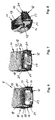
- a deformation element 17 in the form of a box-like crash box integrated ( Figures 3 to 6).
- the deformation element 17 from a bottom 18 with trough-like impressions 19, 20 and two Longitudinal walls 21 and two transverse walls 22, 23 together.
- Both the longitudinal walls 21 and the transverse walls 22, 23 are formed via rounded transitions 24th connected to the floor 18.
- the corner regions 25 between the longitudinal walls 21st and the transverse walls 22, 23 are over the entire height of the deformation element 17 left out.
- In the longitudinal walls 21 are parallel to the end edges 26 of the Walls 21, 22, 23 extending elongated indentations 27 in the form of outward provided depressions.
- transverse walls 22, 23 which is the connection area 6 of the Longitudinal member 2 facing transverse wall 22 shorter than the opposite transverse wall 23rd formed ( Figures 4 and 5).
- depressions 28 embossed.
- these are longer Transverse wall 23 is a parallel to the end edges 26 of the transverse wall 23rd extending trough 29 is stamped from the inside out.
- corrugations 31st connected to the remaining areas 32 are next to the shorter Transverse wall 22 lying portions 30 of the longitudinal walls 21.
- the deformation element 17 is only over the free longitudinal edges 33, 34 of the adjacent to the shorter transverse wall 22 areas 30 and the longer Transverse wall 23 joined to the Sekundärgurt 12, in particular welded.
Landscapes
- Engineering & Computer Science (AREA)
- Mechanical Engineering (AREA)
- General Engineering & Computer Science (AREA)
- Chemical & Material Sciences (AREA)
- Combustion & Propulsion (AREA)
- Transportation (AREA)
- Body Structure For Vehicles (AREA)
- Vibration Dampers (AREA)
Abstract
Description
- Figur 1
- im Schema in der Draufsicht eine Achskonstruktion für ein Kraftfahrzeug;
- Figur 2
- einen vertikalen Querschnitt durch die Darstellung der Figur 1 entlang der Linie II-II in Richtung der Pfeile IIa gesehen;
- Figur 3
- in schematischer Perspektive einen Längsträger der Achskonstruktion der Figuren 1 und 2;
- Figur 4
- in schematischer Perspektive ein Deformationselement für den Längsträger der Figur 3;
- Figur 5
- das Deformationselement der Figur 4 in schematischer Perspektive von der Unterseite her gesehen und
- Figuren 6 bis 8
- in einer Finite-Element-Darstellung den Ausschnitt VI der Figur 2 in drei Betriebssituationen eines Längsträgers.
- 1 -
- Achskonstruktion
- 2 -
- Längsträger v. 1
- 3 -
- Längsträger v. 1
- 4 -
- Querträger v. 1
- 5 -
- Querträger v. 1
- 6 -
- Anbindungsbereich v. 2
- 7 -
- Anbindungsbereich v. 3
- 8 -
- Anbindungsbereich v. 2
- 9 -
- Anbindungsbereich v. 3
- 10 -
- Sollknickbereich v. 2
- 11 -
- Primärgurt
- 12 -
- Sekundärgurt
- 13 -
- Steg v. 11
- 14 -
- Schenkel v. 11
- 15 -
- Seite v. 12
- 16 -
- Längssicken in 15
- 17 -
- Deformationselement
- 18 -
- Boden v. 17
- 19 -
- Einprägung in 18
- 20 -
- Einprägung in 18
- 21 -
- Längswände v. 17
- 22 -
- Querwand v. 17
- 23 -
- Querwand v. 17
- 24 -
- Übergänge zw. 18 u. 21 bzw. 22, 23
- 25 -
- Eckbereiche v. 17
- 26 -
- Stirnkanten v. 21, 22, 23
- 27 -
- Einprägungen in 21
- 28 -
- Mulden in 24
- 29 -
- Mulde in 23
- 30 -
- Bereiche v. 21
- 31 -
- Wellungen in 21
- 32 -
- Bereiche v. 21
- 33 -
- Längskanten v. 30
- 34 -
- Längskanten v. 23
- 35 -
- freie Räume zw. 17 u. 11
Claims (14)
- Längsträger für eine Achskonstruktion (1) eines Kraftfahrzeugs, welcher über den wesentlichen Teil seiner Länge hohl ausgebildet ist und im Längsverlauf mindestens einen Sollknickbereich (10) aufweist, dadurch gekennzeichnet, dass sein Querschnitt durch mindestens zwei miteinander gefügte Längsgurte (11,12) gebildet ist, von denen einer die Funktion eines sich im Sollknickbereich (10) zuerst verformenden Primärgurts (11) aufweist und der gegenüberliegende als sich zeitlich später verformender Sekundärgurt (12) wirkt, wobei in den Sollknickbereich (10) mindestens ein zum Primärgurt (11) distanziertes und mit dem Sekundärgurt (12) gefügtes Deformationselement (17) integriert ist.
- Längsträger nach Anspruch 1, dadurch gekennzeichnet, dass der Primärgurt (11) im Querschnitt U-förmig ausgebildet ist und den streifenartig gestalteten Sekundärgurt (12) überwölbt, wobei das Deformationselement (17) als zum Sekundärgurt (12) hin offene, kastenartige Crashbox mit zwei Längswänden (21) und zwei Querwänden (22,23) ausgebildet und hinsichtlich seine Bodens (18) sowie seiner Längswände (21) mit Abstand zum Steg (13) bzw. zu den Schenkeln (14) des Primärgurts (11) angeordnet ist.
- Längsträger nach Anspruch 2, dadurch gekennzeichnet, dass das Deformationselement (17) mindestens bereichsweise über die freien Kanten (33,34) seiner Wände (21,23) mit dem Sekundärgurt (12) gefügt ist.
- Längsträger nach Anspruch 2 oder 3, dadurch gekennzeichnet, dass die Eckbereiche (25) zwischen den Längswänden (21) und den Querwänden (22,23) über die gesamte Höhe des Deformationselements (17) ausgespart sind.
- Längsträger nach einem der Ansprüche 1 bis 4, dadurch gekennzeichnet, dass der Sollknickbereich (10) bogenförmig ausgebildet ist und das Deformationselement (10) sich auf der konkaven Innenseite (15) des Sekundärgurts (12) erstreckt.
- Längsträger nach einem der Ansprüche 2 bis 5, dadurch gekennzeichnet, dass eine Querwand (22) des Deformationselements (17) kürzer als die andere Querwand (23) ausgebildet ist.
- Längsträger nach Anspruch 5 oder 6, dadurch gekennzeichnet, dass die neben der kürzeren Querwand (22) liegenden Bereiche (30) der Längswände (21) durch Wellungen (31) mit den restlichen Bereichen (32) verbunden sind.
- Längsträger nach Anspruch 7, dadurch gekennzeichnet, dass die neben der kürzeren Querwand (22) liegenden Bereiche (30) der Längswände (21) und die längere Querwand (23) über ihre Längskanten (33,34) mit dem Sekundärgurt (12) gefügt sind.
- Längsträger nach einem der Ansprüche 2 bis 8, dadurch gekennzeichnet, dass im Boden (18) und/oder in den Wänden (21,22,23) des Deformationselements (17) Einprägungen (19,20,27,29) vorgesehen sind.
- Längsträger nach Anspruch 9, dadurch gekennzeichnet, dass die Einprägungen (27) in den Wänden (21) des Deformationselements (17) sich annähernd parallel zu den Stirnkanten (26) der Wände (21) erstrecken.
- Längsträger nach Anspruch 9 oder 10, dadurch gekennzeichnet, dass die Einprägungen (19,20) im Boden (18) des Deformationselements (17) muldenartig ausgebildet sind.
- Längsträger nach einem der Ansprüche 1 bis 11, dadurch gekennzeichnet, dass in den gerundet ausgebildeten Übergang (24) vom Boden (18) des Deformationselements (17) auf die längere Querwand (23) Mulden (28) eingeprägt sind.
- Längsträger nach einem der Ansprüche 1 bis 12, dadurch gekennzeichnet, dass mindestens für den Primärgurt (11) ein höchstfester Werkstoff der Qualität Re >400 MPa mit einer Wanddicke unter 2 mm zum Einsatz gelangt.
- Längsträger nach einem der Ansprüche 1 bis 13, dadurch gekennzeichnet, dass in den Sekundärgurt (12) von der dem Primärgurt (11) zugewandten Seite (15) her Längssicken (16) eingeprägt sind.
Applications Claiming Priority (2)
| Application Number | Priority Date | Filing Date | Title |
|---|---|---|---|
| DE2003157628 DE10357628B3 (de) | 2003-12-10 | 2003-12-10 | Längsträger für eine Achskonstruktion eines Kraftfahrzeugs |
| DE10357628 | 2003-12-10 |
Publications (2)
| Publication Number | Publication Date |
|---|---|
| EP1541447A1 true EP1541447A1 (de) | 2005-06-15 |
| EP1541447B1 EP1541447B1 (de) | 2007-02-07 |
Family
ID=34089310
Family Applications (1)
| Application Number | Title | Priority Date | Filing Date |
|---|---|---|---|
| EP20040027045 Expired - Lifetime EP1541447B1 (de) | 2003-12-10 | 2004-11-13 | Längsträger für eine Achskonstruktion eines Kraftfahrzeugs |
Country Status (2)
| Country | Link |
|---|---|
| EP (1) | EP1541447B1 (de) |
| DE (2) | DE10357628B3 (de) |
Families Citing this family (5)
| Publication number | Priority date | Publication date | Assignee | Title |
|---|---|---|---|---|
| DE102009041771A1 (de) * | 2009-09-16 | 2011-03-17 | Volkswagen Ag | Hilfsrahmen für ein Kraftfahrzeug |
| WO2013064270A1 (de) * | 2011-11-03 | 2013-05-10 | Magna Presstec Ag | Hilfsrahmen mit sicken |
| CN107628118B (zh) * | 2017-09-20 | 2019-09-10 | 吉利汽车研究院(宁波)有限公司 | 一种汽车正面碰撞纵梁结构 |
| DE102023001364B4 (de) | 2023-04-06 | 2024-10-31 | Mercedes-Benz Group AG | Anordnung eines Aggregateträgers an einer Karosserie eines elektrisch antreibbaren Kraftwagens |
| DE102023004418B3 (de) | 2023-11-03 | 2025-01-16 | Mercedes-Benz Group AG | Vorderwagenstruktur für eine Karosserie eines Personenkraftwagens |
Citations (6)
| Publication number | Priority date | Publication date | Assignee | Title |
|---|---|---|---|---|
| DE2254299A1 (de) * | 1971-12-08 | 1973-06-20 | Toyota Motor Co Ltd | Rahmeneinheit zum absorbieren von aufprallenergie |
| US4674770A (en) * | 1984-08-28 | 1987-06-23 | Toyota Jidosha Kabushiki Kaisha | Frame structure for vehicle body |
| GB2332883A (en) * | 1997-12-20 | 1999-07-07 | Rover Group | Energy absorbing vehicle subframe |
| DE19934666A1 (de) * | 1999-07-23 | 2001-01-25 | Porsche Ag | Energieabsorbierender Träger einer Fahrzeugstruktur |
| US6286895B1 (en) * | 1998-04-03 | 2001-09-11 | Honda Giken Kogyo Kabushiki Kaisha | Control device for controlling rigidity and deformation of car body |
| EP1331161A1 (de) * | 2002-01-16 | 2003-07-30 | Nissan Motor Co., Ltd. | Verstärkungskonstruktion für Karosserierahmen von Kraftfahrzeugen |
Family Cites Families (3)
| Publication number | Priority date | Publication date | Assignee | Title |
|---|---|---|---|---|
| JPH05319308A (ja) * | 1992-05-14 | 1993-12-03 | Mazda Motor Corp | 自動車の前部車体構造及びその組立方法 |
| US6007099A (en) * | 1997-12-01 | 1999-12-28 | Ford Global Technologies, Inc. | Vehicle intrusion energy management frame element |
| DE10138437B4 (de) * | 2001-08-06 | 2005-05-04 | Thyssenkrupp Stahl Ag | Aus von Blechprofilen gebildeten Trägern zusammengesetzte Tragstruktur für die Karosserie eines Kraftfahrzeuges |
-
2003
- 2003-12-10 DE DE2003157628 patent/DE10357628B3/de not_active Expired - Fee Related
-
2004
- 2004-11-13 EP EP20040027045 patent/EP1541447B1/de not_active Expired - Lifetime
- 2004-11-13 DE DE200450002848 patent/DE502004002848D1/de not_active Expired - Lifetime
Patent Citations (6)
| Publication number | Priority date | Publication date | Assignee | Title |
|---|---|---|---|---|
| DE2254299A1 (de) * | 1971-12-08 | 1973-06-20 | Toyota Motor Co Ltd | Rahmeneinheit zum absorbieren von aufprallenergie |
| US4674770A (en) * | 1984-08-28 | 1987-06-23 | Toyota Jidosha Kabushiki Kaisha | Frame structure for vehicle body |
| GB2332883A (en) * | 1997-12-20 | 1999-07-07 | Rover Group | Energy absorbing vehicle subframe |
| US6286895B1 (en) * | 1998-04-03 | 2001-09-11 | Honda Giken Kogyo Kabushiki Kaisha | Control device for controlling rigidity and deformation of car body |
| DE19934666A1 (de) * | 1999-07-23 | 2001-01-25 | Porsche Ag | Energieabsorbierender Träger einer Fahrzeugstruktur |
| EP1331161A1 (de) * | 2002-01-16 | 2003-07-30 | Nissan Motor Co., Ltd. | Verstärkungskonstruktion für Karosserierahmen von Kraftfahrzeugen |
Also Published As
| Publication number | Publication date |
|---|---|
| DE10357628B3 (de) | 2005-02-24 |
| EP1541447B1 (de) | 2007-02-07 |
| DE502004002848D1 (de) | 2007-03-22 |
Similar Documents
| Publication | Publication Date | Title |
|---|---|---|
| DE602005002657T2 (de) | Crashbox für fahrzeug | |
| DE19531986B4 (de) | Energie aufnehmende Konstruktion einer Türverkleidung | |
| DE102005044907B4 (de) | Heckseitige Fahrzeugkarosseriestruktur eines Kraftfahrzeugs | |
| DE10326554B4 (de) | Verfahren zum Herstellen einer Stossstangenverstärkung | |
| DE60013761T2 (de) | Fahrzeugrahmen | |
| EP1036715A2 (de) | Stossfängeranordnung | |
| EP1346861B1 (de) | Seitenaufprallträger | |
| DE10324403A1 (de) | Stoßdämpfer | |
| EP3901006B1 (de) | Kraftfahrzeugbauteil | |
| DE2132473A1 (de) | Energieverzehrer,insbesondere zum Befestigen von Stossstangen an Kraftfahrzeugen | |
| DE102007048376A1 (de) | Energieabsorptions-Sitzverankerungs-Rückhaltesystem für Kinder-Sicherheitssitze | |
| DE102004008741A1 (de) | Stoßfängersystem | |
| EP1533192A1 (de) | Stossfängersystem | |
| DE10006348C2 (de) | Bauteil mit lokal begrenzten Versteifungsbereichen und Verfahren zu seiner Herstellung | |
| EP1291247B1 (de) | Frontstruktur eines Kraftfahrzeuges | |
| EP1080954A2 (de) | Querträger als Bestandteil einer Verbundlenkerachse | |
| DE10108279A1 (de) | Aufprallabsorbierende Struktur eines Fahrzeuges | |
| DE102004041165B4 (de) | Fahrzeugkarosseriestruktur | |
| DE3007897C2 (de) | Lastbügel für Fahrzeuge, insbesondere für Kraftfahrzeuge | |
| EP1541447B1 (de) | Längsträger für eine Achskonstruktion eines Kraftfahrzeugs | |
| DE69404421T2 (de) | Stossdämpfer | |
| DE19942973B4 (de) | Fahrzeugsitz mit Crashenergieabsorption | |
| DE10309636B4 (de) | Karosserieträger mit einer den Verformungsverlauf bei einem Aufprall beeinflussenden Nebenform | |
| EP0664244B1 (de) | Dämpfungselement | |
| DE69508544T2 (de) | Energieabsorbierender Balken und dünnes metallisches Blech zu dessen Realisierung |
Legal Events
| Date | Code | Title | Description |
|---|---|---|---|
| PUAI | Public reference made under article 153(3) epc to a published international application that has entered the european phase |
Free format text: ORIGINAL CODE: 0009012 |
|
| AK | Designated contracting states |
Kind code of ref document: A1 Designated state(s): AT BE BG CH CY CZ DE DK EE ES FI FR GB GR HU IE IS IT LI LU MC NL PL PT RO SE SI SK TR |
|
| AX | Request for extension of the european patent |
Extension state: AL HR LT LV MK YU |
|
| 17P | Request for examination filed |
Effective date: 20050426 |
|
| AKX | Designation fees paid |
Designated state(s): CZ DE FR IT |
|
| GRAP | Despatch of communication of intention to grant a patent |
Free format text: ORIGINAL CODE: EPIDOSNIGR1 |
|
| GRAS | Grant fee paid |
Free format text: ORIGINAL CODE: EPIDOSNIGR3 |
|
| GRAA | (expected) grant |
Free format text: ORIGINAL CODE: 0009210 |
|
| AK | Designated contracting states |
Kind code of ref document: B1 Designated state(s): CZ DE FR IT |
|
| REF | Corresponds to: |
Ref document number: 502004002848 Country of ref document: DE Date of ref document: 20070322 Kind code of ref document: P |
|
| ET | Fr: translation filed | ||
| PLBE | No opposition filed within time limit |
Free format text: ORIGINAL CODE: 0009261 |
|
| STAA | Information on the status of an ep patent application or granted ep patent |
Free format text: STATUS: NO OPPOSITION FILED WITHIN TIME LIMIT |
|
| 26N | No opposition filed |
Effective date: 20071108 |
|
| PGFP | Annual fee paid to national office [announced via postgrant information from national office to epo] |
Ref country code: DE Payment date: 20131114 Year of fee payment: 10 Ref country code: FR Payment date: 20131120 Year of fee payment: 10 Ref country code: CZ Payment date: 20131106 Year of fee payment: 10 |
|
| PGFP | Annual fee paid to national office [announced via postgrant information from national office to epo] |
Ref country code: IT Payment date: 20131127 Year of fee payment: 10 |
|
| REG | Reference to a national code |
Ref country code: DE Ref legal event code: R119 Ref document number: 502004002848 Country of ref document: DE |
|
| PG25 | Lapsed in a contracting state [announced via postgrant information from national office to epo] |
Ref country code: CZ Free format text: LAPSE BECAUSE OF NON-PAYMENT OF DUE FEES Effective date: 20141113 |
|
| REG | Reference to a national code |
Ref country code: FR Ref legal event code: ST Effective date: 20150731 |
|
| PG25 | Lapsed in a contracting state [announced via postgrant information from national office to epo] |
Ref country code: DE Free format text: LAPSE BECAUSE OF NON-PAYMENT OF DUE FEES Effective date: 20150602 |
|
| PG25 | Lapsed in a contracting state [announced via postgrant information from national office to epo] |
Ref country code: FR Free format text: LAPSE BECAUSE OF NON-PAYMENT OF DUE FEES Effective date: 20141201 |
|
| PG25 | Lapsed in a contracting state [announced via postgrant information from national office to epo] |
Ref country code: IT Free format text: LAPSE BECAUSE OF NON-PAYMENT OF DUE FEES Effective date: 20141113 |