EP1541427A1 - Knee airbag and occupant's leg protection system - Google Patents
Knee airbag and occupant's leg protection system Download PDFInfo
- Publication number
- EP1541427A1 EP1541427A1 EP04028468A EP04028468A EP1541427A1 EP 1541427 A1 EP1541427 A1 EP 1541427A1 EP 04028468 A EP04028468 A EP 04028468A EP 04028468 A EP04028468 A EP 04028468A EP 1541427 A1 EP1541427 A1 EP 1541427A1
- Authority
- EP
- European Patent Office
- Prior art keywords
- knee airbag
- width portion
- width
- lateral
- inflated
- Prior art date
- Legal status (The legal status is an assumption and is not a legal conclusion. Google has not performed a legal analysis and makes no representation as to the accuracy of the status listed.)
- Granted
Links
- 210000003127 knee Anatomy 0.000 title claims abstract description 96
- 210000002414 leg Anatomy 0.000 title claims abstract description 20
- 239000004744 fabric Substances 0.000 description 5
- 230000037431 insertion Effects 0.000 description 2
- 238000003780 insertion Methods 0.000 description 2
- 230000000452 restraining effect Effects 0.000 description 1
- 230000000717 retained effect Effects 0.000 description 1
- 229920003002 synthetic resin Polymers 0.000 description 1
- 239000000057 synthetic resin Substances 0.000 description 1
Images


Classifications
-
- B—PERFORMING OPERATIONS; TRANSPORTING
- B60—VEHICLES IN GENERAL
- B60R—VEHICLES, VEHICLE FITTINGS, OR VEHICLE PARTS, NOT OTHERWISE PROVIDED FOR
- B60R21/00—Arrangements or fittings on vehicles for protecting or preventing injuries to occupants or pedestrians in case of accidents or other traffic risks
- B60R21/02—Occupant safety arrangements or fittings, e.g. crash pads
- B60R21/16—Inflatable occupant restraints or confinements designed to inflate upon impact or impending impact, e.g. air bags
- B60R21/23—Inflatable members
- B60R21/231—Inflatable members characterised by their shape, construction or spatial configuration
- B60R21/233—Inflatable members characterised by their shape, construction or spatial configuration comprising a plurality of individual compartments; comprising two or more bag-like members, one within the other
-
- B—PERFORMING OPERATIONS; TRANSPORTING
- B60—VEHICLES IN GENERAL
- B60R—VEHICLES, VEHICLE FITTINGS, OR VEHICLE PARTS, NOT OTHERWISE PROVIDED FOR
- B60R21/00—Arrangements or fittings on vehicles for protecting or preventing injuries to occupants or pedestrians in case of accidents or other traffic risks
- B60R21/02—Occupant safety arrangements or fittings, e.g. crash pads
- B60R21/16—Inflatable occupant restraints or confinements designed to inflate upon impact or impending impact, e.g. air bags
- B60R21/23—Inflatable members
- B60R21/231—Inflatable members characterised by their shape, construction or spatial configuration
- B60R21/2334—Expansion control features
- B60R21/2338—Tethers
-
- B—PERFORMING OPERATIONS; TRANSPORTING
- B60—VEHICLES IN GENERAL
- B60R—VEHICLES, VEHICLE FITTINGS, OR VEHICLE PARTS, NOT OTHERWISE PROVIDED FOR
- B60R21/00—Arrangements or fittings on vehicles for protecting or preventing injuries to occupants or pedestrians in case of accidents or other traffic risks
- B60R21/02—Occupant safety arrangements or fittings, e.g. crash pads
- B60R21/16—Inflatable occupant restraints or confinements designed to inflate upon impact or impending impact, e.g. air bags
- B60R21/23—Inflatable members
- B60R21/231—Inflatable members characterised by their shape, construction or spatial configuration
- B60R2021/23169—Inflatable members characterised by their shape, construction or spatial configuration specially adapted for knee protection
-
- B—PERFORMING OPERATIONS; TRANSPORTING
- B60—VEHICLES IN GENERAL
- B60R—VEHICLES, VEHICLE FITTINGS, OR VEHICLE PARTS, NOT OTHERWISE PROVIDED FOR
- B60R21/00—Arrangements or fittings on vehicles for protecting or preventing injuries to occupants or pedestrians in case of accidents or other traffic risks
- B60R21/02—Occupant safety arrangements or fittings, e.g. crash pads
- B60R21/16—Inflatable occupant restraints or confinements designed to inflate upon impact or impending impact, e.g. air bags
- B60R21/23—Inflatable members
- B60R21/231—Inflatable members characterised by their shape, construction or spatial configuration
- B60R21/2334—Expansion control features
- B60R21/2338—Tethers
- B60R2021/23382—Internal tether means
Definitions
- the present invention relates to a knee airbag for restraining the movement of the lower body of an occupant toward the front of a vehicle by restricting the movement of knees to prevent the lower legs of the occupant from striking against an interior panel etc. ahead of a seat in the event of a collision of the vehicle and it relates to an occupant's leg protection system including the knee airbag.
- an occupant's leg protection system for protecting the lower legs of an occupant from striking against the interior panel ahead of a seat to receive a large load in the event of a head-on collision of a highspeed mobile unit such as a car, which includes a knee airbag that is to be inflated toward the front of the occupant's legs and an inflator (gas generator) for inflating the knee airbag.
- Patent Document 1 JP-A-2003-182504 (Patent Document 1) to provide a knee airbag constructed to be inflated from below upward in front of occupant's legs.
- the knee airbag is shaped such that the width of the lower part in lateral directions (hereinafter, also referred to as a lateral width) is smaller at the lower part, in which gas from an inflator is diffused by a diffuser in the lateral directions in the knee airbag, and which includes a tether that joins the base fabric of the knee airbag adjacent to the occupant and the base fabric adjacent to an instrument panel (interior panel) together, and in which the tether is disposed vertically in multistage.
- a lateral width the width of the lower part in lateral directions
- JP-A-2003-182504 are constructed such that the uppermost tether has the smallest width.
- the outline of the uppermost chamber in the knee airbag is not clear and as such, this may delay completion of inflation of the uppermost chamber.
- An airbag according to the present invention is an knee airbag to be inflated toward the front of the legs of a vehicle occupant.
- the knee airbag is to be inflated from below upward, of which the upper part constituting an equal-width portion having a substantially equal lateral width.
- the part lower than the equal-width portion has a smaller width at the lower part.
- Continuous tethers extending laterally are provided vertically in multistages in the knee airbag, the upper tether being longer laterally. Vent spaces are formed between the respective lateral ends of the tethers and the lateral edges of the knee airbag.
- the uppermost tether is located in the vicinity of the boundary between the equal-width portion and the narrow-width portion or above the boundary.
- the knee airbag according to claim 1 may further comprise a diffuser for directing gas from an inflator for inflating the knee airbag only in the lateral directions in the knee airbag is provided at the lower part of the knee airbag (claim 2).
- the knee airbag according to claim 1 or 2 may be further defined in that, when inflated, the vent spaces each having a flow-channel cross section of 3,000 mm 2 to 7,850 mm 2 are formed between the respective lateral ends of the tethers and the edges of the knee airbag.
- An occupant's leg protection system according to the invention includes the knee airbag according to the invention (claims 1, 2 or 3) and an inflator for inflating the knee airbag.
- the gas flows upward through the vent spaces between the both ends of the tethers and the lateral edges of the knee airbag to inflate the uppermost chamber.
- the lateral width of the lower part of the knee airbag is smaller at the lower part (in other words, the lateral width is larger at the upper part).
- the knee airbag is inflated upward while expanding laterally, then the upper part of the knee airbag is inflated so as to connect inflated portions of the lateral edges to extend laterally, and then the vicinity of the center of the knee airbag is inflated.
- the uppermost tether has the largest lateral width and is located in the vicinity of the boundary between the equal-width portion and the narrow-width portion or above the boundary portion, and the uppermost chamber of the knee airbag is relatively small in volume. Accordingly the uppermost chamber of the knee airbag is inflated quickly.
- the lateral sides and the upper part of the knee airbag are inflated quickly to be deployed laterally and upward rapidly.
- the gas from the inflator is directed laterally. Therefore, the knee airbag is deployed laterally more quickly.
- the gas from the inflator flows upward along the edges of the knee airbag quickly. Therefore, the knee airbag is inflated extremely quickly.
- An occupant's leg protection system 14 is mounted to an interior panel 10 ahead of a seat 12.
- the occupant's leg protection system 14 includes a container-like retainer 16 that is open in the front (a surface adjacent to an occupant), a knee airbag 18 connected to the retainer 16, an inflator (gas generator) 20 for inflating the knee airbag 18, and a diffuser 22 disposed in the knee airbag 18 for directing the gas flow laterally in the knee airbag 18.
- the retainer 16 is disposed in an opening 10a of the interior panel 10.
- the knee airbag 18 and the diffuser 22 are usually accommodated in an folded state in the retainer 16.
- a lid 24 is attached to the front surface of the retainer 16 such that it covers the folded knee airbag 18.
- the lid 24 is usually disposed so as to be substantially flush with the interior panel 10 and, when the knee airbag 18 is inflated, the lid 24 is open to the front surface of the interior panel 10 with the lower end as fulcrum, as shown in Fig. 1.
- the opening 10a is provided lower than the seating surface of the seat 12.
- the knee airbag 18 is inflated from below upward along the front surface (a surface adjacent to the occupant) of the interior panel 10 from the opening 10a.
- the upper part of the knee airbag 18 constitutes an equal-width portion 26 of which the lateral width is substantially equal across a predetermined vertical width.
- the part of the knee airbag 18 lower than the equal-width portion 26 constitutes a narrow-width portion 28 of which the lateral width is smaller at the lower part.
- the lower end of the narrow-width portion 28 is connected to the retainer 16.
- the equal-width portion 26 is disposed such that it is located above the seating surface of the seat 12 when the knee airbag 18 is inflated from below upward along the front surface of the interior panel 10 through the opening 10a. Therefore, when the knee airbag 18 is inflated toward the front of occupant's legs, the equal-width portion 26 faces the vicinity of the knees of the occupant seated in the seat 12.
- the lateral width of the equal-width portion 26 is preferably in the range from 500 mm to 600 mm.
- the lateral width of the front opening of the retainer 16 is preferably at most one-half, particularly from 40% to 50% of the width of the equal-width portion 26.
- the narrow-width portion 28 preferably extends such that the lateral edges thereof connect the lateral edges of the equal-width portion 26 with the lateral lower corners of the front opening of the retainer 16, respectively.
- the knee airbag 18 has tethers 30 and 32 that connect the front surface (a base fabric adjacent to the occupant) 18a of the knee airbag 18 and the rear surface (a base fabric adjacent to the interior panel 10) 18b in multistages (two stages in this embodiment).
- Symbol S denotes seams that connect the tethers 30 and 32 with the front surface 18a and the rear surface 18b, respectively.
- the upper tether 30 is disposed in the vicinity of the boundary between the equal-width portion 26 and the narrow-width portion 28 or at a position slightly upper than that (preferably, in the range of 0 mm to 70 mm above the boundary between the equal-width portion 26 and the narrow-width portion 28).
- the lower tether 32 is disposed in the vertical middle of the narrow-width portion 28.
- the tethers 30 and 32 extend in the lateral directions and connect to the front surface 18a and the rear surface 18b across a predetermined lateral width. As shown in Fig. 2(b), the respective lateral ends of the tethers 30 and 32 are separated from the lateral edges of the knee airbag 18. Between the lateral ends of the tethers 30 and 32 and the lateral edges of the knee airbag 18, vent spaces V are formed, respectively.
- the cross section of the flow channel of each vent space V is preferably in the range from 3,000 mm 2 to 7,850 mm 2 , more preferably, from 4,500 m 2 to 5,500 mm 2 .
- the interval (the shortest distance) between the respective both ends of the tethers 30 and 32 and the lateral edges of the knee airbag 18 is preferably in the range from 80 mm to 130 mm, more preferably, from 90 mm to 120 mm.
- line L 1 that connects the left ends of the tethers 30 and 32 together and line L 2 that connects the right ends together are parallel to lines L 3 and L 4 that extend along the lateral edges of the narrow-width portion 28, respectively, and the distances d between the lines L1 and L3 and between the lines L2 and L4 are preferably in the range from 80 mm to 130 mm, more preferably, from 90 mm to 120 mm.
- gas from the inflator 20 flows quickly upward along the lateral edges of the narrow-width portion 28 through the vent spaces V.
- the diffuser 22 is disposed in the narrow-width portion 28.
- the inflator 20 is disposed in the diffuser 22.
- the diffuser 22 is constructed such that a heat-resistance soft fabric or synthetic resin is formed in cylindrical shape by stitching, of which the openings 22a and 22b at the opposite ends are disposed so as to be open in the lateral directions. Therefore, when the inflator 20 emits a jet of gas in the diffuser 22, the gas from the inflator 20 is directed only laterally through the openings 22a and 22b.
- the diffuser 22 has a size that allows it to be inflated so as to project forward (toward the occupant) relative to the front surface of the interior panel 10 in the knee airbag 18, shown in Fig. 4, by the pressure of the gas emitted from the inflator 20 in the diffuser 22.
- the size of the diffuser 22 is preferably set such that the projection length P (see Fig. 4) of the diffuser 22 from the front surface of the interior panel 10 is in the range from 60 mm to 100 mm, or the areas of the openings 22a and 22b projecting from the front surface of the interior panel 10 and exposed into the knee airbag 18 are in the range from 3,000 mm 2 to 7,850 mm 2 .
- the inflator 20 of this embodiment is shaped like a rod and disposed in the diffuser 22 such that the longitudinal direction is the lateral direction.
- the inflator 20 has gas ports (not shown) in the side circumference thereof.
- the inflator 20 is mounted to an inflator holder 34.
- the inflator holder 34 includes a base portion and a band portion (the reference numerals are omitted) which fixes the inflator 20 to the base portion. Stud bolts 34a project from the base portion.
- the stud bolts 34a are inserted into bolt insertion holes (the reference numerals are omitted) provided in the rear surface of the diffuser 22 (opposite to the occupant) and the rear surface 18b at the lower end of the narrow-width portion 28 to project to the back of the knee airbag 18 (opposite to the occupant) and further inserted into bolt insertion holes (the reference numerals are omitted) provided in the retainer 16.
- Nuts 34b are fastened to the stud bolts 34a, so that the inflator holder 34 is fixed in the retainer 16 and the rear surface of the diffuser 22 and the rear surface 18b at the lower end of the narrow-width portion 28 are retained between the inflator holder 34 and the retainer 16.
- the inflator 20 emits a jet of gas and so the knee airbag 18 starts to be inflated by the gas from the inflator 20.
- the knee airbag 18 pushes the lid 24 open to be inflated toward the front of the interior panel 10 and is deployed upward along the interior panel 10.
- the equal-width portion 26 at the upper part of the inflated knee airbag 18 faces the vicinity of occupant's knees and receives them.
- the knee airbag 18 has a shape in which the lower narrow-width portion 28 is smaller in lateral width at the lower part, or an upward expanding shape, and the gas from the inflator 20 disposed at the lower end of the narrow-width portion 28 flows upward through the vent spaces V between the lateral ends of the tethers 30 and 32 and the lateral edges of the narrow-width portion 28.
- the narrow-width portion 28 first is inflated while expanding upward and laterally, then the equal-width portion 26 above the narrow-width portion 28 is inflated to extend laterally so as to connect the inflated portions of the lateral sides of the narrow-width portion 28 together, and then the vicinity of the center of the knee airbag 18 is inflated.
- the upper tether 30 is disposed in the vicinity of the boundary between the equal-width portion 26 and the narrow-width portion 28 or at a position upper than that and has a large lateral width.
- the equal-width portion 26 has a relatively small volume and so the equal-width portion 26 is inflated rapidly.
- the lateral sides and the upper equal- width portion 26 of the knee airbag 18 are inflated quickly, so that the knee airbag 18 is inflated laterally and upward quickly.
- the knee airbag 18 is deployed laterally extremely quickly.
- the diffuser 22 projects from the front surface of the interior panel 10 forward by 60 mm to 100 mm in the knee airbag 18 by the pressure of the gas emitted from the inflator 20. Therefore, the gas from the inflator 20 is emitted laterally from the lateral openings 22a and 22b of the diffuser 22 without striking against the inner surface of the knee airbag 18 to change the directions. Accordingly, the gas from the inflator 20 can be effectively directed laterally.
- the cross section of the flow channel of each of the vent spaces V between the both ends of the tethers 30 and 32 and the lateral edges of the narrow-width portion 28 is in the range from 3,000 mm 2 to 7,850 mm 2 .
- the gas flows upward quickly in the vent spaces V. Accordingly, the knee airbag 18 is inflated extremely rapidly.
Landscapes
- Engineering & Computer Science (AREA)
- Mechanical Engineering (AREA)
- Air Bags (AREA)
Abstract
Description
- The present invention relates to a knee airbag for restraining the movement of the lower body of an occupant toward the front of a vehicle by restricting the movement of knees to prevent the lower legs of the occupant from striking against an interior panel etc. ahead of a seat in the event of a collision of the vehicle and it relates to an occupant's leg protection system including the knee airbag.
- There is an occupant's leg protection system for protecting the lower legs of an occupant from striking against the interior panel ahead of a seat to receive a large load in the event of a head-on collision of a highspeed mobile unit such as a car, which includes a knee airbag that is to be inflated toward the front of the occupant's legs and an inflator (gas generator) for inflating the knee airbag.
- It is described in JP-A-2003-182504 (Patent Document 1) to provide a knee airbag constructed to be inflated from below upward in front of occupant's legs. The knee airbag is shaped such that the width of the lower part in lateral directions (hereinafter, also referred to as a lateral width) is smaller at the lower part, in which gas from an inflator is diffused by a diffuser in the lateral directions in the knee airbag, and which includes a tether that joins the base fabric of the knee airbag adjacent to the occupant and the base fabric adjacent to an instrument panel (interior panel) together, and in which the tether is disposed vertically in multistage.
- The tethers disclosed in JP-A-2003-182504 are constructed such that the uppermost tether has the smallest width. Thus the outline of the uppermost chamber in the knee airbag is not clear and as such, this may delay completion of inflation of the uppermost chamber.
- Accordingly, it is an object of the present invention to provide a knee airbag that is disposed vertically and laterally quickly and an occupant's leg protection system including the knee airbag.
- An airbag according to the present invention (Claim 1) is an knee airbag to be inflated toward the front of the legs of a vehicle occupant. The knee airbag is to be inflated from below upward, of which the upper part constituting an equal-width portion having a substantially equal lateral width. The part lower than the equal-width portion has a smaller width at the lower part. Continuous tethers extending laterally are provided vertically in multistages in the knee airbag, the upper tether being longer laterally. Vent spaces are formed between the respective lateral ends of the tethers and the lateral edges of the knee airbag. The uppermost tether is located in the vicinity of the boundary between the equal-width portion and the narrow-width portion or above the boundary.
- The knee airbag according to claim 1 may further comprise a diffuser for directing gas from an inflator for inflating the knee airbag only in the lateral directions in the knee airbag is provided at the lower part of the knee airbag (claim 2).
- The knee airbag according to claim 1 or 2 may be further defined in that, when inflated, the vent spaces each having a flow-channel cross section of 3,000 mm2 to 7,850 mm2 are formed between the respective lateral ends of the tethers and the edges of the knee airbag.
- An occupant's leg protection system according to the invention (Claim 4) includes the knee airbag according to the invention (claims 1, 2 or 3) and an inflator for inflating the knee airbag.
- In the knee airbag and the occupant's leg protection system according to the present invention, when the knee airbag is inflated by the gas from the inflator, the gas flows upward through the vent spaces between the both ends of the tethers and the lateral edges of the knee airbag to inflate the uppermost chamber. The lateral width of the lower part of the knee airbag is smaller at the lower part (in other words, the lateral width is larger at the upper part).
- Accordingly, at inflation, the knee airbag is inflated upward while expanding laterally, then the upper part of the knee airbag is inflated so as to connect inflated portions of the lateral edges to extend laterally, and then the vicinity of the center of the knee airbag is inflated.
- Of the tethers of the knee airbag, the uppermost tether has the largest lateral width and is located in the vicinity of the boundary between the equal-width portion and the narrow-width portion or above the boundary portion, and the uppermost chamber of the knee airbag is relatively small in volume. Accordingly the uppermost chamber of the knee airbag is inflated quickly.
- Thus, according to the invention, the lateral sides and the upper part of the knee airbag are inflated quickly to be deployed laterally and upward rapidly.
- According to claim 2, the gas from the inflator is directed laterally. Therefore, the knee airbag is deployed laterally more quickly.
- According to claim 3, the gas from the inflator flows upward along the edges of the knee airbag quickly. Therefore, the knee airbag is inflated extremely quickly.
- An embodiment of the present invention will be described hereinbelow with reference to the drawings.
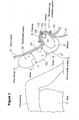
- Fig. 1 is a cross-sectional view of the vicinity ahead of a vehicle seat showing the inflated state of a knee airbag according to an embodiment of the present invention;
- Fig. 2(a) is a front view of the knee airbag of Fig. 1, showing the inflated state thereof;
- Fig. 2(b) is a cross-sectional view taken along line B-B of Fig. 2(a);
- Fig. 3 is a cross-sectional view taken along line III-III of Fig. 2(b); and
- Fig. 4 is a cross-sectional view taken along line IV-IV of Fig. 1. In the following description, a lateral direction means a direction along the width of a vehicle.
-
- An occupant's
leg protection system 14 is mounted to aninterior panel 10 ahead of aseat 12. - The occupant's
leg protection system 14 includes a container-like retainer 16 that is open in the front (a surface adjacent to an occupant), aknee airbag 18 connected to theretainer 16, an inflator (gas generator) 20 for inflating theknee airbag 18, and adiffuser 22 disposed in theknee airbag 18 for directing the gas flow laterally in theknee airbag 18. - The
retainer 16 is disposed in an opening 10a of theinterior panel 10. Theknee airbag 18 and thediffuser 22 are usually accommodated in an folded state in theretainer 16. Alid 24 is attached to the front surface of theretainer 16 such that it covers the foldedknee airbag 18. Thelid 24 is usually disposed so as to be substantially flush with theinterior panel 10 and, when theknee airbag 18 is inflated, thelid 24 is open to the front surface of theinterior panel 10 with the lower end as fulcrum, as shown in Fig. 1. - As shown in Fig. 1, the opening 10a is provided lower than the seating surface of the
seat 12. Theknee airbag 18 is inflated from below upward along the front surface (a surface adjacent to the occupant) of theinterior panel 10 from the opening 10a. - Referring to Fig. 2, the upper part of the
knee airbag 18 constitutes an equal-width portion 26 of which the lateral width is substantially equal across a predetermined vertical width. The part of theknee airbag 18 lower than the equal-width portion 26 constitutes a narrow-width portion 28 of which the lateral width is smaller at the lower part. The lower end of the narrow-width portion 28 is connected to theretainer 16. - The equal-
width portion 26 is disposed such that it is located above the seating surface of theseat 12 when theknee airbag 18 is inflated from below upward along the front surface of theinterior panel 10 through the opening 10a. Therefore, when theknee airbag 18 is inflated toward the front of occupant's legs, the equal-width portion 26 faces the vicinity of the knees of the occupant seated in theseat 12. - The lateral width of the equal-
width portion 26 is preferably in the range from 500 mm to 600 mm. The lateral width of the front opening of theretainer 16 is preferably at most one-half, particularly from 40% to 50% of the width of the equal-width portion 26. - Referring to Fig. 4, the narrow-
width portion 28 preferably extends such that the lateral edges thereof connect the lateral edges of the equal-width portion 26 with the lateral lower corners of the front opening of theretainer 16, respectively. - The
knee airbag 18 has tethers 30 and 32 that connect the front surface (a base fabric adjacent to the occupant) 18a of theknee airbag 18 and the rear surface (a base fabric adjacent to the interior panel 10) 18b in multistages (two stages in this embodiment). Symbol S denotes seams that connect thetethers front surface 18a and therear surface 18b, respectively. Theupper tether 30 is disposed in the vicinity of the boundary between the equal-width portion 26 and the narrow-width portion 28 or at a position slightly upper than that (preferably, in the range of 0 mm to 70 mm above the boundary between the equal-width portion 26 and the narrow-width portion 28). Thelower tether 32 is disposed in the vertical middle of the narrow-width portion 28. - The
tethers front surface 18a and therear surface 18b across a predetermined lateral width. As shown in Fig. 2(b), the respective lateral ends of thetethers knee airbag 18. Between the lateral ends of thetethers knee airbag 18, vent spaces V are formed, respectively. - The cross section of the flow channel of each vent space V is preferably in the range from 3,000 mm2 to 7,850 mm2, more preferably, from 4,500 m2 to 5,500 mm2. In that case, the interval (the shortest distance) between the respective both ends of the
tethers knee airbag 18 is preferably in the range from 80 mm to 130 mm, more preferably, from 90 mm to 120 mm. - In the invention, particularly, as shown in Fig. 3, line L1 that connects the left ends of the
tethers width portion 28, respectively, and the distances d between the lines L1 and L3 and between the lines L2 and L4 are preferably in the range from 80 mm to 130 mm, more preferably, from 90 mm to 120 mm. With such a structure, gas from theinflator 20 flows quickly upward along the lateral edges of the narrow-width portion 28 through the vent spaces V. - The
diffuser 22 is disposed in the narrow-width portion 28. Theinflator 20 is disposed in thediffuser 22. According to the embodiment, thediffuser 22 is constructed such that a heat-resistance soft fabric or synthetic resin is formed in cylindrical shape by stitching, of which theopenings inflator 20 emits a jet of gas in thediffuser 22, the gas from theinflator 20 is directed only laterally through theopenings - In the embodiment, the
diffuser 22 has a size that allows it to be inflated so as to project forward (toward the occupant) relative to the front surface of theinterior panel 10 in theknee airbag 18, shown in Fig. 4, by the pressure of the gas emitted from theinflator 20 in thediffuser 22. The size of thediffuser 22 is preferably set such that the projection length P (see Fig. 4) of thediffuser 22 from the front surface of theinterior panel 10 is in the range from 60 mm to 100 mm, or the areas of theopenings interior panel 10 and exposed into theknee airbag 18 are in the range from 3,000 mm2 to 7,850 mm2. - The
inflator 20 of this embodiment is shaped like a rod and disposed in thediffuser 22 such that the longitudinal direction is the lateral direction. The inflator 20 has gas ports (not shown) in the side circumference thereof. - The inflator 20 is mounted to an
inflator holder 34. Theinflator holder 34 includes a base portion and a band portion (the reference numerals are omitted) which fixes the inflator 20 to the base portion.Stud bolts 34a project from the base portion. - The
stud bolts 34a are inserted into bolt insertion holes (the reference numerals are omitted) provided in the rear surface of the diffuser 22 (opposite to the occupant) and therear surface 18b at the lower end of the narrow-width portion 28 to project to the back of the knee airbag 18 (opposite to the occupant) and further inserted into bolt insertion holes (the reference numerals are omitted) provided in theretainer 16.Nuts 34b are fastened to thestud bolts 34a, so that theinflator holder 34 is fixed in theretainer 16 and the rear surface of thediffuser 22 and therear surface 18b at the lower end of the narrow-width portion 28 are retained between theinflator holder 34 and theretainer 16. - When a vehicle equipped with the occupant's
leg protection system 14 with such a structure collides at the front, theinflator 20 emits a jet of gas and so theknee airbag 18 starts to be inflated by the gas from theinflator 20. Theknee airbag 18 pushes thelid 24 open to be inflated toward the front of theinterior panel 10 and is deployed upward along theinterior panel 10. The equal-width portion 26 at the upper part of theinflated knee airbag 18 faces the vicinity of occupant's knees and receives them. - In the occupant's
leg protection system 14, theknee airbag 18 has a shape in which the lower narrow-width portion 28 is smaller in lateral width at the lower part, or an upward expanding shape, and the gas from the inflator 20 disposed at the lower end of the narrow-width portion 28 flows upward through the vent spaces V between the lateral ends of thetethers width portion 28. Therefore, at the inflation of theknee airbag 18, the narrow-width portion 28 first is inflated while expanding upward and laterally, then the equal-width portion 26 above the narrow-width portion 28 is inflated to extend laterally so as to connect the inflated portions of the lateral sides of the narrow-width portion 28 together, and then the vicinity of the center of theknee airbag 18 is inflated. - The
upper tether 30 is disposed in the vicinity of the boundary between the equal-width portion 26 and the narrow-width portion 28 or at a position upper than that and has a large lateral width. The equal-width portion 26 has a relatively small volume and so the equal-width portion 26 is inflated rapidly. - Accordingly, the lateral sides and the upper equal-
width portion 26 of theknee airbag 18 are inflated quickly, so that theknee airbag 18 is inflated laterally and upward quickly. - According to the embodiment, since the
diffuser 22 that directs the gas flow from the inflator 20 laterally is provided, theknee airbag 18 is deployed laterally extremely quickly. - According to the embodiment, when the
knee airbag 18 is inflated, thediffuser 22 projects from the front surface of theinterior panel 10 forward by 60 mm to 100 mm in theknee airbag 18 by the pressure of the gas emitted from theinflator 20. Therefore, the gas from the inflator 20 is emitted laterally from thelateral openings diffuser 22 without striking against the inner surface of theknee airbag 18 to change the directions. Accordingly, the gas from the inflator 20 can be effectively directed laterally. - In this embodiment, the cross section of the flow channel of each of the vent spaces V between the both ends of the
tethers width portion 28 is in the range from 3,000 mm2 to 7,850 mm2. Thus, the gas flows upward quickly in the vent spaces V. Accordingly, theknee airbag 18 is inflated extremely rapidly. - The above-described embodiment is only an example of the invention; the invention is not limited to that.
Claims (4)
- A knee airbag to be inflated toward the front of the legs of a vehicle occupant, wherein
the knee airbag is to be inflated from below upward, of which the upper part constituting an equal-width portion having a substantially equal lateral width; and
the part lower than the equal-width portion has a smaller width at the lower part, wherein
continuous tethers extending laterally are provided vertically in multistage in the knee airbag, the upper tether being longer laterally;
vent spaces are formed between the respective lateral ends of the tethers and the lateral edges of the knee airbag; and
the uppermost tether is located in the vicinity of the boundary between the equal-width portion and the narrow-width portion or above the boundary. - The knee airbag according to Claim 1, wherein a diffuser for directing gas from an inflator for inflating the knee airbag only laterally in the knee airbag is provided at the lower part of the knee airbag.
- The knee airbag according to claim 1 or 2, when inflated, the vent spaces each having a flow-channel cross section of 3,000 mm2 to 7,850 mm2 are formed between the respective lateral ends of the tethers and the edges of the knee airbag.
- An occupant's leg protection system comprising a knee airbag to be inflated toward the front of the legs of a vehicle occupant and an inflator for inflating the knee airbag, wherein the knee airbag is the knee airbag according to one of claims 1 to 3.
Applications Claiming Priority (2)
| Application Number | Priority Date | Filing Date | Title |
|---|---|---|---|
| JP2003415191 | 2003-12-12 | ||
| JP2003415191A JP4553577B2 (en) | 2003-12-12 | 2003-12-12 | Knee bag and occupant leg protection device |
Publications (2)
| Publication Number | Publication Date |
|---|---|
| EP1541427A1 true EP1541427A1 (en) | 2005-06-15 |
| EP1541427B1 EP1541427B1 (en) | 2009-02-25 |
Family
ID=34510571
Family Applications (1)
| Application Number | Title | Priority Date | Filing Date |
|---|---|---|---|
| EP04028468A Expired - Lifetime EP1541427B1 (en) | 2003-12-12 | 2004-12-01 | Knee airbag and occupant's leg protection system |
Country Status (5)
| Country | Link |
|---|---|
| US (1) | US7322599B2 (en) |
| EP (1) | EP1541427B1 (en) |
| JP (1) | JP4553577B2 (en) |
| CN (1) | CN100436202C (en) |
| DE (1) | DE602004019619D1 (en) |
Cited By (2)
| Publication number | Priority date | Publication date | Assignee | Title |
|---|---|---|---|---|
| CN101443215B (en) * | 2006-05-15 | 2011-06-01 | 丰田自动车株式会社 | Air bag device for protection of knee, method of developing air bag device for protection of knee, and vehicle |
| CN104853962A (en) * | 2012-11-05 | 2015-08-19 | 关键安全体系股份有限公司 | Improved airbag with enhanced gas diffuser |
Families Citing this family (11)
| Publication number | Priority date | Publication date | Assignee | Title |
|---|---|---|---|---|
| JP2005343180A (en) * | 2004-05-31 | 2005-12-15 | Nippon Plast Co Ltd | Airbag device |
| DE102005049209A1 (en) * | 2005-10-07 | 2007-04-12 | Takata-Petri Ag | Airbag arrangement for an airbag module of a motor vehicle |
| JP4793910B2 (en) * | 2005-10-24 | 2011-10-12 | タカタ株式会社 | Passenger leg restraining device |
| US7942440B2 (en) * | 2005-12-22 | 2011-05-17 | Autoliv Asp, Inc. | Channel and diffuser airbag |
| JP4793104B2 (en) * | 2006-06-01 | 2011-10-12 | 豊田合成株式会社 | Side airbag device |
| JP4591574B2 (en) * | 2008-08-06 | 2010-12-01 | トヨタ自動車株式会社 | Knee airbag device for vehicle |
| DE102008060858B4 (en) * | 2008-12-09 | 2012-03-01 | Autoliv Development Ab | Knee airbag |
| US8590928B2 (en) * | 2011-07-18 | 2013-11-26 | Ford Global Technologies, Llc | Knee airbag with passive venting for out of position occupant protection |
| JP2013209007A (en) * | 2012-03-30 | 2013-10-10 | Toyoda Gosei Co Ltd | Airbag for passenger seat |
| CN105747645A (en) * | 2016-03-22 | 2016-07-13 | 盐城工学院 | An Electric 4D Cinema Seat Safety Device |
| US12257971B1 (en) * | 2023-10-17 | 2025-03-25 | Autoliv Asp, Inc. | Knee airbag for a vehicle |
Citations (4)
| Publication number | Priority date | Publication date | Assignee | Title |
|---|---|---|---|---|
| US6155595A (en) * | 1998-04-23 | 2000-12-05 | Trw Occupant Restraint Systems Gmbh & Co. Kg | Knee protection device for vehicle occupants |
| EP1310408A2 (en) * | 2001-11-09 | 2003-05-14 | Toyoda Gosei Co., Ltd. | Knee airbag with tether arrangement |
| EP1314617A2 (en) * | 2001-11-22 | 2003-05-28 | Toyoda Gosei Co., Ltd. | Knee protecting airbag device |
| EP1350689A2 (en) * | 2002-04-01 | 2003-10-08 | Toyoda Gosei Co., Ltd. | Airbag device |
Family Cites Families (7)
| Publication number | Priority date | Publication date | Assignee | Title |
|---|---|---|---|---|
| CA2145485C (en) * | 1994-05-23 | 1999-01-05 | Autoliv Asp, Inc. | Air bag activated knee bolster |
| JP3772742B2 (en) * | 2001-12-25 | 2006-05-10 | 豊田合成株式会社 | Air bag device for knee protection |
| JP3687602B2 (en) * | 2001-12-10 | 2005-08-24 | トヨタ自動車株式会社 | Vehicle occupant knee protection device |
| JP3767497B2 (en) * | 2002-03-01 | 2006-04-19 | トヨタ自動車株式会社 | Vehicle occupant knee protection device |
| JP3948332B2 (en) * | 2002-04-15 | 2007-07-25 | タカタ株式会社 | Crew protection device |
| DE10360509B4 (en) * | 2002-12-27 | 2012-04-26 | Toyoda Gosei Co., Ltd. | Knee-protecting airbag device |
| JP4063712B2 (en) * | 2003-05-22 | 2008-03-19 | 豊田合成株式会社 | Air bag device for knee protection |
-
2003
- 2003-12-12 JP JP2003415191A patent/JP4553577B2/en not_active Expired - Fee Related
-
2004
- 2004-11-18 CN CNB2004100947934A patent/CN100436202C/en not_active Expired - Fee Related
- 2004-12-01 EP EP04028468A patent/EP1541427B1/en not_active Expired - Lifetime
- 2004-12-01 DE DE602004019619T patent/DE602004019619D1/en not_active Expired - Lifetime
- 2004-12-07 US US11/004,940 patent/US7322599B2/en not_active Expired - Lifetime
Patent Citations (4)
| Publication number | Priority date | Publication date | Assignee | Title |
|---|---|---|---|---|
| US6155595A (en) * | 1998-04-23 | 2000-12-05 | Trw Occupant Restraint Systems Gmbh & Co. Kg | Knee protection device for vehicle occupants |
| EP1310408A2 (en) * | 2001-11-09 | 2003-05-14 | Toyoda Gosei Co., Ltd. | Knee airbag with tether arrangement |
| EP1314617A2 (en) * | 2001-11-22 | 2003-05-28 | Toyoda Gosei Co., Ltd. | Knee protecting airbag device |
| EP1350689A2 (en) * | 2002-04-01 | 2003-10-08 | Toyoda Gosei Co., Ltd. | Airbag device |
Cited By (3)
| Publication number | Priority date | Publication date | Assignee | Title |
|---|---|---|---|---|
| CN101443215B (en) * | 2006-05-15 | 2011-06-01 | 丰田自动车株式会社 | Air bag device for protection of knee, method of developing air bag device for protection of knee, and vehicle |
| CN104853962A (en) * | 2012-11-05 | 2015-08-19 | 关键安全体系股份有限公司 | Improved airbag with enhanced gas diffuser |
| CN104853962B (en) * | 2012-11-05 | 2018-06-29 | 关键安全体系股份有限公司 | Improvement air bag with enhancing gaseous diffuser |
Also Published As
| Publication number | Publication date |
|---|---|
| US20050127643A1 (en) | 2005-06-16 |
| JP2005170292A (en) | 2005-06-30 |
| CN1626384A (en) | 2005-06-15 |
| CN100436202C (en) | 2008-11-26 |
| US7322599B2 (en) | 2008-01-29 |
| EP1541427B1 (en) | 2009-02-25 |
| JP4553577B2 (en) | 2010-09-29 |
| DE602004019619D1 (en) | 2009-04-09 |
Similar Documents
| Publication | Publication Date | Title |
|---|---|---|
| EP1544054B1 (en) | Vehicle comprising an occupant's leg protection system with a knee airbag | |
| US7669895B2 (en) | Knee-bag and occupant leg protection apparatus | |
| US6361067B1 (en) | Airbag with interior deflection device | |
| US7267366B2 (en) | Airbag, airbag device and vehicle | |
| KR100846055B1 (en) | Airbag with vertical groove | |
| USRE43353E1 (en) | Divided airbag system | |
| US20050098994A1 (en) | Airbag cushion with angled recess | |
| EP1541427B1 (en) | Knee airbag and occupant's leg protection system | |
| US20040251665A1 (en) | Occupant leg protection apparatus | |
| JP6582872B2 (en) | Passenger leg restraining device | |
| JP2008296642A (en) | Airbag system | |
| JP2004330959A (en) | Occupant leg safety device | |
| JP2005096653A (en) | Rear seat airbag and rear seat airbag device | |
| JP2007125989A (en) | Occupant leg restraining device and retainer | |
| JP2019131161A (en) | Far side airbag device | |
| CN112124244B (en) | Knee airbag device for vehicle | |
| EP1431132B1 (en) | Occupant's leg protection system | |
| JP2009023493A (en) | Airbag device | |
| JP2010006374A (en) | Knee bag and occupant's leg protection apparatus | |
| KR20070113831A (en) | Airbag cushion |
Legal Events
| Date | Code | Title | Description |
|---|---|---|---|
| PUAI | Public reference made under article 153(3) epc to a published international application that has entered the european phase |
Free format text: ORIGINAL CODE: 0009012 |
|
| AK | Designated contracting states |
Kind code of ref document: A1 Designated state(s): AT BE BG CH CY CZ DE DK EE ES FI FR GB GR HU IE IS IT LI LT LU MC NL PL PT RO SE SI SK TR |
|
| AX | Request for extension of the european patent |
Extension state: AL BA HR LV MK YU |
|
| 17P | Request for examination filed |
Effective date: 20051110 |
|
| AKX | Designation fees paid |
Designated state(s): DE FR GB SE |
|
| GRAP | Despatch of communication of intention to grant a patent |
Free format text: ORIGINAL CODE: EPIDOSNIGR1 |
|
| GRAS | Grant fee paid |
Free format text: ORIGINAL CODE: EPIDOSNIGR3 |
|
| GRAS | Grant fee paid |
Free format text: ORIGINAL CODE: EPIDOSNIGR3 |
|
| GRAA | (expected) grant |
Free format text: ORIGINAL CODE: 0009210 |
|
| AK | Designated contracting states |
Kind code of ref document: B1 Designated state(s): DE FR GB SE |
|
| REG | Reference to a national code |
Ref country code: GB Ref legal event code: FG4D |
|
| REF | Corresponds to: |
Ref document number: 602004019619 Country of ref document: DE Date of ref document: 20090409 Kind code of ref document: P |
|
| PG25 | Lapsed in a contracting state [announced via postgrant information from national office to epo] |
Ref country code: SE Free format text: LAPSE BECAUSE OF FAILURE TO SUBMIT A TRANSLATION OF THE DESCRIPTION OR TO PAY THE FEE WITHIN THE PRESCRIBED TIME-LIMIT Effective date: 20090525 |
|
| PLBE | No opposition filed within time limit |
Free format text: ORIGINAL CODE: 0009261 |
|
| STAA | Information on the status of an ep patent application or granted ep patent |
Free format text: STATUS: NO OPPOSITION FILED WITHIN TIME LIMIT |
|
| 26N | No opposition filed |
Effective date: 20091126 |
|
| REG | Reference to a national code |
Ref country code: FR Ref legal event code: ST Effective date: 20100831 |
|
| PG25 | Lapsed in a contracting state [announced via postgrant information from national office to epo] |
Ref country code: FR Free format text: LAPSE BECAUSE OF NON-PAYMENT OF DUE FEES Effective date: 20091231 |
|
| PGFP | Annual fee paid to national office [announced via postgrant information from national office to epo] |
Ref country code: GB Payment date: 20131127 Year of fee payment: 10 |
|
| GBPC | Gb: european patent ceased through non-payment of renewal fee |
Effective date: 20141201 |
|
| PG25 | Lapsed in a contracting state [announced via postgrant information from national office to epo] |
Ref country code: GB Free format text: LAPSE BECAUSE OF NON-PAYMENT OF DUE FEES Effective date: 20141201 |
|
| REG | Reference to a national code |
Ref country code: DE Ref legal event code: R082 Ref document number: 602004019619 Country of ref document: DE Representative=s name: VOSSIUS & PARTNER PATENTANWAELTE RECHTSANWAELT, DE Ref country code: DE Ref legal event code: R081 Ref document number: 602004019619 Country of ref document: DE Owner name: JOYSON SAFETY SYSTEMS JAPAN K.K., JP Free format text: FORMER OWNER: TAKATA CORP., TOKIO/TOKYO, JP |
|
| PGFP | Annual fee paid to national office [announced via postgrant information from national office to epo] |
Ref country code: DE Payment date: 20201211 Year of fee payment: 17 |
|
| REG | Reference to a national code |
Ref country code: DE Ref legal event code: R119 Ref document number: 602004019619 Country of ref document: DE |
|
| PG25 | Lapsed in a contracting state [announced via postgrant information from national office to epo] |
Ref country code: DE Free format text: LAPSE BECAUSE OF NON-PAYMENT OF DUE FEES Effective date: 20220701 |