EP1541318A1 - Method of manufacturing thermoplastic resin container - Google Patents
Method of manufacturing thermoplastic resin container Download PDFInfo
- Publication number
- EP1541318A1 EP1541318A1 EP03765298A EP03765298A EP1541318A1 EP 1541318 A1 EP1541318 A1 EP 1541318A1 EP 03765298 A EP03765298 A EP 03765298A EP 03765298 A EP03765298 A EP 03765298A EP 1541318 A1 EP1541318 A1 EP 1541318A1
- Authority
- EP
- European Patent Office
- Prior art keywords
- thermoplastic resin
- vessel
- forming
- manufacturing
- sheet
- Prior art date
- Legal status (The legal status is an assumption and is not a legal conclusion. Google has not performed a legal analysis and makes no representation as to the accuracy of the status listed.)
- Granted
Links
Images






Classifications
-
- B—PERFORMING OPERATIONS; TRANSPORTING
- B29—WORKING OF PLASTICS; WORKING OF SUBSTANCES IN A PLASTIC STATE IN GENERAL
- B29C—SHAPING OR JOINING OF PLASTICS; SHAPING OF MATERIAL IN A PLASTIC STATE, NOT OTHERWISE PROVIDED FOR; AFTER-TREATMENT OF THE SHAPED PRODUCTS, e.g. REPAIRING
- B29C51/00—Shaping by thermoforming, i.e. shaping sheets or sheet like preforms after heating, e.g. shaping sheets in matched moulds or by deep-drawing; Apparatus therefor
- B29C51/08—Deep drawing or matched-mould forming, i.e. using mechanical means only
-
- B—PERFORMING OPERATIONS; TRANSPORTING
- B29—WORKING OF PLASTICS; WORKING OF SUBSTANCES IN A PLASTIC STATE IN GENERAL
- B29C—SHAPING OR JOINING OF PLASTICS; SHAPING OF MATERIAL IN A PLASTIC STATE, NOT OTHERWISE PROVIDED FOR; AFTER-TREATMENT OF THE SHAPED PRODUCTS, e.g. REPAIRING
- B29C51/00—Shaping by thermoforming, i.e. shaping sheets or sheet like preforms after heating, e.g. shaping sheets in matched moulds or by deep-drawing; Apparatus therefor
- B29C51/04—Combined thermoforming and prestretching, e.g. biaxial stretching
-
- B—PERFORMING OPERATIONS; TRANSPORTING
- B29—WORKING OF PLASTICS; WORKING OF SUBSTANCES IN A PLASTIC STATE IN GENERAL
- B29C—SHAPING OR JOINING OF PLASTICS; SHAPING OF MATERIAL IN A PLASTIC STATE, NOT OTHERWISE PROVIDED FOR; AFTER-TREATMENT OF THE SHAPED PRODUCTS, e.g. REPAIRING
- B29C49/00—Blow-moulding, i.e. blowing a preform or parison to a desired shape within a mould; Apparatus therefor
- B29C49/02—Combined blow-moulding and manufacture of the preform or the parison
- B29C49/04—Extrusion blow-moulding
- B29C49/0411—Means for defining the wall or layer thickness
- B29C49/04114—Means for defining the wall or layer thickness for keeping constant thickness
-
- B—PERFORMING OPERATIONS; TRANSPORTING
- B29—WORKING OF PLASTICS; WORKING OF SUBSTANCES IN A PLASTIC STATE IN GENERAL
- B29C—SHAPING OR JOINING OF PLASTICS; SHAPING OF MATERIAL IN A PLASTIC STATE, NOT OTHERWISE PROVIDED FOR; AFTER-TREATMENT OF THE SHAPED PRODUCTS, e.g. REPAIRING
- B29C2791/00—Shaping characteristics in general
- B29C2791/004—Shaping under special conditions
- B29C2791/006—Using vacuum
-
- B—PERFORMING OPERATIONS; TRANSPORTING
- B29—WORKING OF PLASTICS; WORKING OF SUBSTANCES IN A PLASTIC STATE IN GENERAL
- B29C—SHAPING OR JOINING OF PLASTICS; SHAPING OF MATERIAL IN A PLASTIC STATE, NOT OTHERWISE PROVIDED FOR; AFTER-TREATMENT OF THE SHAPED PRODUCTS, e.g. REPAIRING
- B29C2791/00—Shaping characteristics in general
- B29C2791/004—Shaping under special conditions
- B29C2791/007—Using fluid under pressure
-
- B—PERFORMING OPERATIONS; TRANSPORTING
- B29—WORKING OF PLASTICS; WORKING OF SUBSTANCES IN A PLASTIC STATE IN GENERAL
- B29C—SHAPING OR JOINING OF PLASTICS; SHAPING OF MATERIAL IN A PLASTIC STATE, NOT OTHERWISE PROVIDED FOR; AFTER-TREATMENT OF THE SHAPED PRODUCTS, e.g. REPAIRING
- B29C51/00—Shaping by thermoforming, i.e. shaping sheets or sheet like preforms after heating, e.g. shaping sheets in matched moulds or by deep-drawing; Apparatus therefor
- B29C51/26—Component parts, details or accessories; Auxiliary operations
- B29C51/261—Handling means, e.g. transfer means, feeding means
- B29C51/262—Clamping means for the sheets, e.g. clamping frames
-
- B—PERFORMING OPERATIONS; TRANSPORTING
- B29—WORKING OF PLASTICS; WORKING OF SUBSTANCES IN A PLASTIC STATE IN GENERAL
- B29L—INDEXING SCHEME ASSOCIATED WITH SUBCLASS B29C, RELATING TO PARTICULAR ARTICLES
- B29L2031/00—Other particular articles
- B29L2031/712—Containers; Packaging elements or accessories, Packages
- B29L2031/7132—Bowls, Cups, Glasses
Definitions
- the present invention relates to a method for manufacturing a vessel obtained by thermally forming a sheet of a thermoplastic resin, particularly to a method for manufacturing a vessel, in which a vessel bottom part is thickened, and generation of warpage in a flange portion is prevented.
- thermoplastic polyester such as polyethylene terephthalate is superior in transparency in addition to the shock resistance, has a gas barrier property, and has therefore been broadly used in various vessels.
- thermoplastic resin vessel there has been a flanged vessel constituted by thermally forming a drawn or non-drawn sheet of a thermoplastic resin.
- this type of vessel for example, there has been a method in which a sheet of softened polyethylene terephthalate is deep-drawn and brought into contact with the interior of a female mold heated at a glass transition point or a higher temperature using a male plug, heat-set, thereafter shrunk back on a male plug, and cooled to manufacture the vessel (Japanese Patent Application Laid-Open No. 58-89319).
- the sheet of polyethylene terephthalate can be drawn to thereby impart transparency, or heat-set to thereby enhance heat resistance.
- An object of the present invention is to provide a method for manufacturing a thermoplastic resin vessel in which thickening of a vessel bottom part and warpage of the flange portion have been improved in consideration of the above-described problem.
- the present inventors have found that in a step of forming a thermoplastic resin sheet into a vessel by a plug, first the thermoplastic resin sheet is pre-formed by the plug, a pre-formed portion of the thermoplastic resin sheet is next clamped, thereafter the plug is inserted into the sheet to a stroke end to thereby form (draw) a vessel main body, and accordingly the thickening of the vessel bottom part and the warpage of the flange portion are improved, and the present invention has been completed.
- thermoplastic resin vessel in which a cup-shaped vessel is thermally formed from a thermoplastic resin sheet by a plug, the method comprising the steps of: pre-forming the thermoplastic resin sheet by the plug; and next clamping the pre-formed portion of the thermoplastic resin sheet to accomplish the forming.
- the step of clamping the portion may be performed while the pre-forming continues to the forming (the forming which does not involve stopping of the plug), or may be performed after the pre-forming ends (once stopping the plug).
- the resin sheet may not be drawn by the pre-forming, but a portion corresponding to an orifice portion or a flange portion of the vessel in the resin sheet is more preferably drawn by the pre-forming.
- the orifice portion When the portion corresponding to the vessel orifice portion is pre-formed in this manner, the orifice portion is oriented/crystallized, and the warpage after the forming can be improved.
- the portion corresponding to the vessel orifice portion is drawn before forming the vessel main body, the resin can be drawn into the vessel from a portion that has heretofore been treated as a skeleton. Therefore, the bottom part of the vessel can be thickened.
- the orifice portion means the orifice portion and its periphery.
- the manufacturing method of the present invention is suitable especially for the manufacturing of a flanged cup-shaped vessel. That is, according to the present invention, there is provided a method for manufacturing a thermoplastic resin vessel, in which a flanged cup-shaped vessel is thermally formed from a thermoplastic resin sheet by a plug, the method comprising the steps of: pre-forming a portion corresponding to the flange portion to thereby draw a resin from the portion corresponding to the flange portion and/or its outer periphery; clamping the drawn portion of the thermoplastic resin sheet after the pre-forming; extruding a part of the resin in the portion corresponding to the flange portion in flange inner and outer peripheral directions; and forming the flange portion.
- the flange portion is oriented/crystallized, and the warpage after the forming can be improved.
- the resin can be drawn into a vessel side from a portion that has heretofore been treated as a skeleton, and the bottom part of the vessel can be thickened.
- the resin flows into a flange portion interior (inner peripheral direction) and a flange portion exterior (outer peripheral direction) from a portion corresponding to the flange portion of the clamped sheet. Therefore, flow orientation occurs in the clamped flange portion, orientation crystallization is promoted, and therefore the warpage after the forming can be improved.
- the flange portion means the flange portion including its periphery.
- the pre-forming by the plug preferably has a step (hereinafter referred to as a pre-clamping step) of fixing an outer periphery of a portion to be formed, that is, the outer periphery of the portion corresponding to the orifice portion or the flange portion of the vessel.
- a mold apparatus 90 is used in which a large number of forming molds 91 are arranged adjacent to one another.
- a resin sheet is taken among the adjacent molds.
- an interval between the mold and the peripheral mold 91 or a frame member 92 differs, and a resin amount between them also differs. Therefore, there is a problem that a difference is made in a drawn-in amount of the resin, and a thickness of the vessel fluctuates between the vessels and in the vessel itself.
- thermoplastic resin vessel comprising: a step of pre-clamping an outer periphery of a pre-formed portion, that is, the outer periphery of the portion corresponding to an orifice portion or a flange portion.
- the resin sheet can be prevented from being taken among the molds.
- the difference of the drawn-in resin amount, attributed to the arrangement of the molds, can be solved, and a thickness, weight and the like of the vessel can be uniformed.
- lubricants such as silicone oil, palm oil, and vegetable oils including Grammar wax are preferably applied to at least a portion of the thermoplastic resin sheet corresponding to the flange portion.
- the lubricant may be applied only to an outer surface in a case where an influence onto a content is to be reduced.
- thermoplastic resin sheet is preferably formed of a thermoplastic polyester resin.
- the thermoplastic resin sheet may comprise a single layer of the thermoplastic polyester resin, or a multiple layers with other resins including a polyester resin.
- thermoplastic polyester resin is oriented/crystallized, and thermally crystallized through a drawing step and a thermal fixing (heat-setting) step, and accordingly mechanical strength, transparency, and heat resistance are enhanced.
- thermal forming is preferably a forming method comprising the steps of: pneumatically forming and thermally fixing the thermoplastic resin sheet into a shape of a lower mold heated at a temperature which is not less than a crystallization temperature of the thermoplastic resin sheet; thereafter decompressing the inside of a formed article to contract the formed article; and imparting and cooling a shape of the plug which is a final vessel shape.
- thermoplastic polyester resin In this case, the mechanical strength, transparency, and heat resistance of the thermoplastic polyester resin are enhanced.
- the cup-shaped vessel is preferably formed in such a manner that H/D (height/orifice portion inner diameter) is 1.3 to 2.1.
- the resin of the portion which has not heretofore been used in the vessel can be used, and therefore the vessel bottom part can be thickened.
- the ratio is smaller than 1.3, there is a possibility that the resin is insufficiently drawn, the orientation crystallization is not performed, and the transparency of the vessel drops.
- the ratio is greater than 2.1, the shaping becomes difficult.
- the ratio is preferably 1.3 to 1.8. That is, the present invention is suitable for manufacturing a deep drawn vessel.
- an area drawing magnification of the vessel bottom part is preferably set to 3.5 to 10 times. Especially, 3.5 to 9 times are preferable.
- magnification when the magnification is less than 3.5 times, the orientation drawing becomes insufficient, the transparency drops, and the vessel is brittle.
- magnification exceeds ten times, there is a possibility that the strength drops because of the thinning, the resin hardens because of excessive orientation crystallization, and the shaping becomes difficult.
- FIGS. 1 to 10 are figures showing an embodiment in which the manufacturing method of the present invention is applied to a solid phase forming method.
- FIG. 1 is a schematic side sectional view of a solid-phase forming apparatus example for carrying out the manufacturing method of the present invention.
- a forming apparatus 1 mainly comprises a plug 11, a lower mold 12, an upper mold 13, an upper pre-clamp mold 14, and a lower pre-clamp mold 15.
- the plug 11 is disposed for drawing/forming a thermoplastic resin sheet 16, and has a shape of a final formed article for contracting/shaping a drawn/heat-set (thermally fixed) sheet.
- a gas passage 111 for compression and decompression is disposed in an axial direction.
- the lower mold 12 is disposed for heat-setting the sheet detached from the plug.
- a flange grasping surface 122 which forms a flange portion in cooperation with the upper mold 13 is disposed.
- a gas passage 121 for discharging and supplying a gas is formed in a central portion of the lower mold 12.
- the lower mold 12 is disposed coaxially with the plug 11, and the plug 11 and the lower mold 12 are relatively movable in the axial direction in such a manner that the plug 11 is inserted into and detached from the lower mold 12.
- the upper mold 13 cooperates with the lower mold 12 to form the flange portion (orifice portion), and constitutes a short hollow cylindrical article. Therefore, the upper mold 13 has an inner surface 131 having a diameter substantially equal to that of a cylindrical inner surface of the lower mold 12, and a grasping surface 132 having the same shape as that of the flange grasping surface 122 of the lower mold 12 is disposed on a lower end face of the upper mold. It is to be noted that these flange grasping surfaces of the upper/lower molds may be flat surfaces, and concave/convex portions may be disposed in one or both of the molds if necessary.
- the upper pre-clamp mold 14 and the lower pre-clamp mold 15 are coaxially disposed on outer peripheries of the upper mold 13 and the lower mold 12, and cooperate with each other to fix the thermoplastic resin sheet.
- the lower pre-clamp mold 15 operates independent of the plug 11 and the lower mold 12.
- a temperature of the sheet at this time depends on a resin for use, and is set to a glass transition point (Tg) to (Tg+45)°C in the sheet of a polyester resin.
- Tg glass transition point
- Tg+45 glass transition point
- orientation crystallization does not sufficiently occur, and there is a possibility that a whitening phenomenon occurs by thermal crystallization in a subsequent heat setting step.
- Tg°C glass transition point
- the temperature is lower than Tg°C, a high forming force is required, additionally the forming itself is difficult, and there is a possibility that the resin has an excessively drawn state at the time of the forming, and the whitening phenomenon occurs.
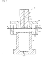
- FIG. 2 is a side sectional view at a time when the thermoplastic resin sheet 16 is pre-clamped by the upper pre-clamp mold 14 and the lower pre-clamp mold 15.
- the sheet 16 is usually clamped by four or two sides by a frame. Therefore, when the sheet having an influenced size is used, the pre-clamping is preferably performed. However, when a sheet sufficiently larger than the vessel to be formed is used, the pre-clamping step may be omitted.
- the temperature of the pre-clamp mold is preferably not more than a softening point or a melting point of the sheet resin, and the cooling may be performed if necessary.
- the pre-clamp mold is cooled, vessel deformation caused by thermal deformation of the sheet can be inhibited at a time when the sheet solidifies after a mold releasing step.
- the pre-clamp mold As the temperature of the pre-clamp mold, for example, when the sheet is obtained substantially as an amorphous or low-crystalline sheet as in the polyester resin, the pre-clamp mold is preferably cooled at not more than the glass transition temperature of the resin. On the other hand, when the sheet is substantially crystallized and obtained as in polypropylene, the pre-clamp mold is preferably cooled at not more than a softening point of the resin.
- the grasping surface of the pre-clamp may have a flat surface, crest cut shape, or concave/convex rib shape.
- the rib shape is disposed, rigidity can be imparted to the sheet after punching, and an effect similar to that obtained when the pre-clamp mold is cooled is obtained.
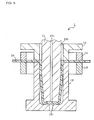
- FIG. 3 is a side sectional view showing a step (pre-forming step) of drawing a portion corresponding to a vessel orifice portion or flange portion to thereby draw the resin from the outer periphery of the orifice portion.
- the sheet 16 is pushed downwards by a predetermined amount by the plug 11. Accordingly, a portion forming a flange portion (orifice portion) is drawn in a subsequent step. Therefore, since the flange portion is oriented/crystallized, warpage after the shaping can be prevented.
- the resin is drawn into an area (forming area) inside the orifice portion or the flange portion from the outer periphery of the portion forming the vessel orifice portion or flange portion. Accordingly, the resin of the outer peripheral portion of the vessel orifice portion or the flange portion, which has not heretofore been used in the vessel, can be effectively used, and the thickness of the bottom part of the vessel can be increased.
- the temperature of the plug 11 at this time is 70°C to 110°C, preferably 80°C to 100°C, for example, in the case of a polyester resin sheet.
- a push-in amount (pre-forming amount) of the plug 11 is appropriately adjusted in consideration of the shape (thickness, height, bottom area, etc.) of the vessel to be manufactured, a pre-clamped area, the thickness of the resin sheet, and the like.
- the pre-forming amount is excessively large, the drawn-in amount of the resin is excessively large, and the whole vessel, particularly the resin of the vessel bottom part cannot be subjected to sufficient drawing. As a result, the formed vessel has a possibility that sufficient orientation crystallization cannot be achieved, and the bottom part is whitened.
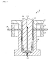
- FIG. 4 is a side sectional view showing a step of clamping a drawn portion of the thermoplastic resin sheet to accomplish forming.
- the lower mold 12 rises, and accordingly cooperates with the upper mold 13, and the flange portion (orifice portion) is clamped and formed by the respective grasping surfaces 122, 132.
- the flange portion is clamped by the upper mold 13 and the lower mold 12, and accordingly flows and is oriented.
- lubricants such as silicone oil, palm oil, and vegetable oils including Grammar wax
- the clamped portion is crushed, a part of the resin is pushed out of the portion, and easily flows to the inside and outside of the flange portion, flow orientation of the resin in the clamped flange portion becomes remarkable, the orientation crystallization is promoted, and the warpage of the flange portion is further improved.
- the temperature of the upper mold is preferably room temperature to 150°C, especially preferably 50°C to 130°C in the case of the polyester resin sheet.
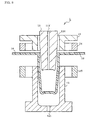
- FIG. 5 is a side sectional view showing a drawing step for forming a vessel main body.
- the plug 11 is inserted into the lower mold 12 to the stroke end, and accordingly the sheet 16 is drawn, oriented, and crystallized.
- FIG. 6 is a side sectional view showing a heat setting step.
- compressed air is supplied (pneumatically) via the gas passage 111 of the plug 11, and the sheet 16 is brought into contact with the inner surface of the lower mold 12.
- the lower mold 12 is heated beforehand, and heat is applied to the sheet to thereby heat-set the sheet.
- air may be sucked from the gas passage 121 of the lower mold 12. In this case, the sheet satisfactorily closely contacts the lower mold 12, and it is possible to effectively heat-set the sheet.
- the temperature of the lower mold 12 at a heat-setting time is preferably 120°C to 200°C, especially preferably 140°C to 180°C in the case of the polyester resin sheet.
- the mold temperature is set to be not more than the glass transition temperature
- the cooling/shaping is performed in a state in which the sheet is brought into close contact with the mold, and a final vessel may be taken out.
- FIG. 7 is a side sectional view showing a cooling/shaping step.
- the compressed air supplied from the passage 111 of the plug 11 is stopped, and the sheet is self-shrunk. Moreover, the air is sucked via the gas passage 111, vacuum is drawn between the sheet and the plug, and the sheet is formed into the shape of the outer surface of the plug 11. At this time the compressed air may be supplied from the gas passage 121 of the lower mold 12. In this case, adhesion is improved, and shaping property is enhanced.
- FIG. 8 is a side sectional view showing a mold releasing step.
- the mold and the pre-clamp mold are opened, the plug 11 is raised, and the final formed article is taken out.
- the method for manufacturing of the vessel of the present invention can be also preferably applied to a case where a vessel having an oval planar sectional shape as shown in FIG. 9 or a vessel having a square planar sectional shape is manufactured.
- FIG. 9 is a plan view of a forming apparatus at a time when the vessel having the oval sectional shape is manufactured
- FIG. 10 is a plan view of the forming apparatus at a time when the vessel having the square sectional shape is manufactured.
- the pre-clamping area needs to be formed into a shape analogous to that of a flange inner end of the cup-shaped vessel, when the thickness, weight or the like of the vessel is uniformed.
- an interval between a straight line portion of the flange inner end of the cup-shaped vessel and the pre-clamping area is increased so that the thickness distribution control is possible.
- the interval between the flange inner end of the cup-shaped vessel and the pre-clamping area in a long side portion is set to be larger than that in a short side portion.
- the sheet indicates a dynamic anisotropy by molecular orientation or the like, this is considered in adjusting the pre-clamping area so that the control of the thickness distribution is possible.
- the method for manufacturing the vessel of the present invention is applicable to either sheets formed of crystalline resins including polyolefin-based resins such as polyethylene, polypropylene, and polystyrene or polyamide-based resins such as polyamide 6, polyamide 66, and polyamide 46, or sheets formed of amorphous resins including polyester-based resins such as polyethylene terephthalate (PET) and polybutylene terephthalate, polycarbonate, polyarylate, and annular olefin-based copolymer. These sheets may be not only single-layer sheet but also sheets having a plurality of layers.
- PET polyethylene terephthalate
- polybutylene terephthalate polybutylene terephthalate
- polycarbonate polyarylate
- annular olefin-based copolymer annular olefin-based copolymer
- a sheet of a polyester-based resin having at least one polyester layer is preferably used.
- polyester for use examples include: polyester derived from a carboxylic acid component mainly composed of aromatic dicarboxylic acid and an alcohol component mainly composed of fatty diol; and preferably polyester in which 50 mol% or more of the carboxylic acid component comprises a terephthalic acid component and 50 mol% or more of the alcohol component comprises a ethylene glycol component.
- Polyester may be homo-polyester, copolymer polyester, or a blend of two or more types of them as long as this condition is satisfied.
- carboxylic acid component other than the terephthalic acid examples include isophthal acid, naphthalene dicarboxylic acid, P- ⁇ -oxyethoxy benzoic acid, biphenyl-4,4'-dicarboxylic acid, diphenoxyethane-4,4'-dicarboxylic acid, 5-sodium sulfoisophthalic acid, hexahydroterephthalic acid, adipic acid, sebacic acid, trimellitic acid, pyromellitic acid and the like.
- examples of the alcohol components other than ethylene glycol include alcohol components such as 1,4-butanediol, propylene glycol, neopentyl glycol, 1,6-hexylene glycol, diethylene glycol, triethylene glycol, cyclohexane dimethanol, ethylene oxide addition product of bisphenol A, glycerol, trimethyrol propane, pentaerythritol, dipentaerythritol, and sorbitan.
- thermoplastic polyester for example, polyethylene terephthalate is most preferable, and the other examples include polyethylene/butylene terephthalate, polyethylene terephthalate/2,6-naphthalate, polyethylene terephthalate/isophthalate, these components and polybutylene terephthalate, polybutylene terephthalate/isophthalate, polyethylene-2,6-naphthalate, polybutylene terephthalate/adipate, polyethylene-2,6-naphthalate/isophthalate, polybutylene terephthalate/adipate, a blend of two or more types of them and the like.
- a molecular weight of polyester is preferably a molecular weight in a film forming range.
- an inherent viscosity [IV] measured using a phenol/tetrachloroethane mixed solvent as a solvent is preferably 0.5 or more, especially in a range of 0.6 to 1.5 in formability, mechanical property, heat resistance and the like.
- modified resin components may be contained such as ethylene-based polymer, thermoplastic elastomer, polyarylate, and polycarbonate.
- the modified resin components are preferably used in the amount of 50 weight parts per 100 weight parts of polyester, especially preferably 5 to 35 weight parts.
- known compounding agents for plastic such as antioxidant, heat stabilizer,ultraviolet absorber, charging preventive agent, filler, colorant and the like can be blended.
- fillers such as calcium carbonate, calcium silicate, alumina, silica, various clays, casting plaster, talc, and magnesia, or inorganic or organic pigments such as titanium white, yellow iron oxide, colcothar, ultramarine blue, and chromium oxide may be blended.
- the thermoplastic resin sheet may have a gas barrier resin layer, a recycle polyester resin layer, oxygen absorbing resin layer and the like in addition to the polyester layer.
- the other resin layer may be used as an inner or outer layer in a double-layer constitution, or as an intermediate layer in a three-layer constitution.
- the thickness of the thermoplastic resin sheet differs with a size or the like of the vessel, but a thickness of 0.5 to 5 mm, especially 1 to 3 mm is preferable in strength or formability of the vessel.
- the vessel manufactured by the manufacturing method of the present invention has a thickened bottom part, and the vessel has a satisfactory self reliance or self stability. Since an area drawing magnification is also appropriate, transparency, shock resistance, and heat resistance are superior.
- the flange portion is oriented/crystallized, a shaping property is enhanced, and warpage is improved.
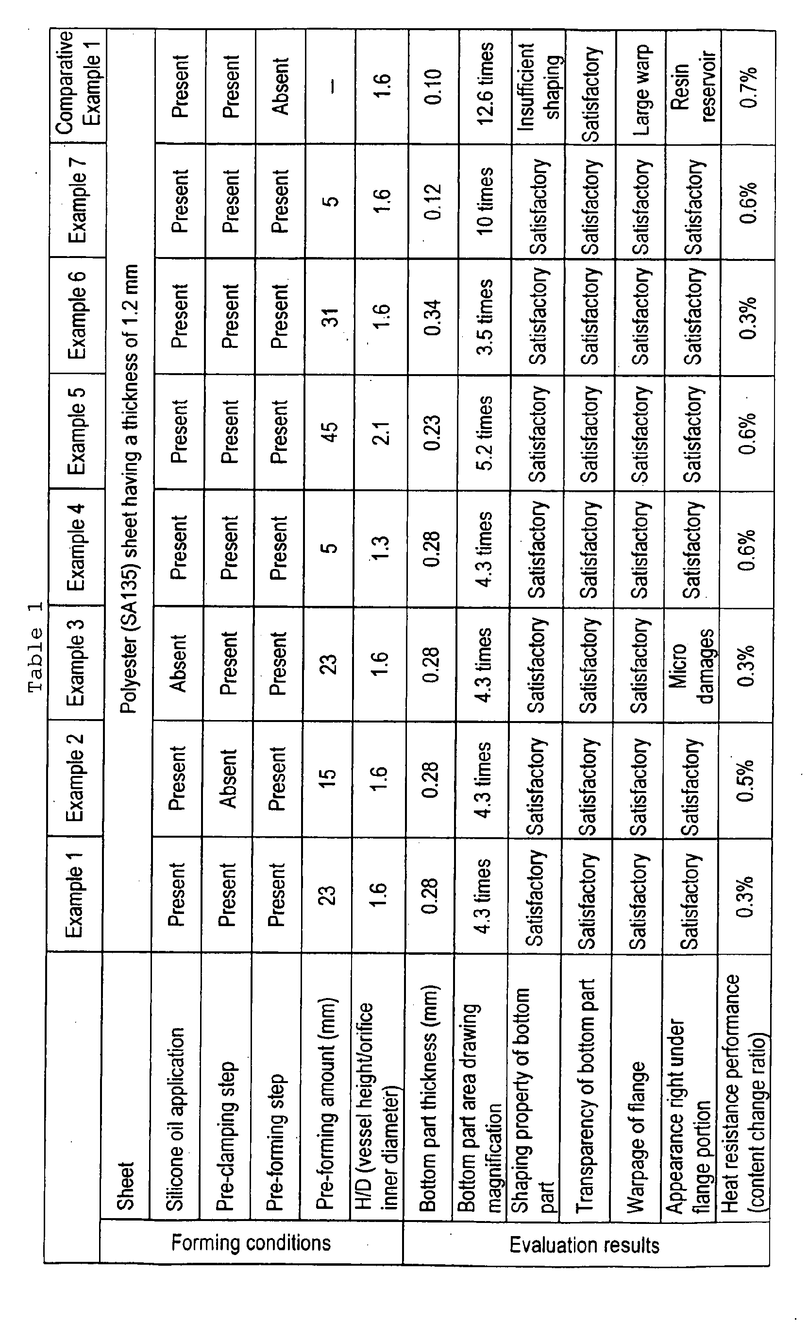
- a cup-shaped vessel was manufactured by a method described above in the embodiment.
- a thermoplastic resin sheet a sheet (manufactured by Mitsui Chemical Co., Ltd., trade name: SA135) of amorphous polyethylene terephthalate having a thickness of 1.2 mm and a glass transition temperature of 75°C was used, and further the sheet surface was coated with silicone oil (manufactured by Shin-Etsu Silicone Co., Ltd., trade name: KM-871P).
- the vessel was manufactured on the following forming conditions:
- a cup-shaped vessel was manufactured on the same conditions as those of Example 1 except that pre-clamping was not performed, and an insertion amount of a plug in first drawing was set to 15 mm. Evaluation was performed in the same manner as in Example 1, and results are shown in Table 1.
- a cup-shaped vessel was manufactured on the same conditions as those of Example 1 except that a portion corresponding to a flange portion was not coated with silicone oil. Evaluation was performed in the same manner as in Example 1, and results are shown in Table 1.
- a cup-shaped vessel was manufactured on the same conditions as those of Example 1 except that a plug height was set to 90 mm, a lower mold dimension was adjusted in such a manner that a clearance between a plug and each portion was about 1 mm, H/D (vessel height/orifice portion inner diameter) was set to 1.3, and an insertion amount of the plug in first drawing was set to 5 mm. Evaluation was performed in the same manner as in Example 1, and results are shown in Table 1.
- a cup-shaped vessel was manufactured on the same conditions as those of Example 1 except that a plug height was set to 145 mm, a lower mold dimension was adjusted in such a manner that a clearance between a plug and each portion was about 1 mm, H/D was set to 2.1, an insertion amount of the plug in first drawing was set to 45 mm, and pre-clamp grasping surface inner diameter was set to 120 mm. Evaluation was performed in the same manner as in Example 1, and results are shown in Table 1.
- a cup-shaped vessel was manufactured on the same conditions as those of Example 1 except that an insertion amount of a plug in first drawing was set to 31 mm. Evaluation was performed in the same manner as in Example 1, and results are shown in Table 1.
- a cup-shaped vessel was manufactured on the same conditions as those of Example 1 except that an insertion amount of a plug in first drawing was set to 5.4 mm. Evaluation was performed in the same manner as in Example 1, and results are shown in Table 1.
- a cup-shaped vessel was manufactured on the same conditions as those of Example 1 except that a pre-forming step was omitted. It is to be noted that in this case there is not any effect of pre-clamping in that a resin is prevented from being taken among molds.
- the manufactured vessel was evaluated in the same manner as in Example 1, and results are shown in Table 1.
- thermoplastic resin vessel in which thickening of a vessel bottom part and warpage of a flange portion are improved.
Landscapes
- Engineering & Computer Science (AREA)
- Mechanical Engineering (AREA)
- Manufacturing & Machinery (AREA)
- Blow-Moulding Or Thermoforming Of Plastics Or The Like (AREA)
- Containers Having Bodies Formed In One Piece (AREA)
- Heating, Cooling, Or Curing Plastics Or The Like In General (AREA)
- Lining Or Joining Of Plastics Or The Like (AREA)
- Processing And Handling Of Plastics And Other Materials For Molding In General (AREA)
Abstract
Description
Claims (14)
- A method for manufacturing a thermoplastic resin vessel, in which a cup-shaped vessel is thermally formed from a thermoplastic resin sheet by a plug, the method comprising the steps of:pre-forming the thermoplastic resin sheet by the plug; and next clamping the pre-formed portion of the thermoplastic resin sheet to accomplish the forming.
- The method for manufacturing the thermoplastic resin vessel according to claim 1, wherein the pre-forming step comprises the steps of: fixing a formed portion outer periphery of the thermoplastic resin sheet.
- The method for manufacturing the thermoplastic resin vessel according to claim 1, wherein the pre-forming step comprises the steps of: drawing a portion corresponding to an orifice portion or a flange portion of the cup-shaped vessel.
- The method for manufacturing the thermoplastic resin vessel according to claim 2, wherein the pre-forming step comprises the steps of: drawing a portion corresponding to an orifice portion or a flange portion of the cup-shaped vessel.
- The method for manufacturing the thermoplastic resin vessel according to claim 3, wherein the clamping step comprises the steps of: extruding a part of a resin in the portion corresponding to the flange portion in flange inner and outer peripheral directions; and forming the flange portion.
- The method for manufacturing the thermoplastic resin vessel according to claim 4, wherein the clamping step comprises the steps of: extruding a part of a resin in the portion corresponding to the flange portion in flange inner and outer peripheral directions; and forming the flange portion.
- The method for manufacturing the thermoplastic resin vessel according to claim 3, further comprising the steps of: applying a lubricant to at least a portion of the thermoplastic resin sheet corresponding to the flange portion.
- The method for manufacturing the thermoplastic resin vessel according to claim 4, further comprising the steps of: applying a lubricant to at least a portion of the thermoplastic resin sheet corresponding to the flange portion.
- The method for manufacturing the thermoplastic resin vessel according to claim 5, further comprising the steps of: applying a lubricant to at least a portion of the thermoplastic resin sheet corresponding to the flange portion.
- The method for manufacturing the thermoplastic resin vessel according to claim 6, further comprising the steps of: applying a lubricant to at least a portion of the thermoplastic resin sheet corresponding to the flange portion.
- The method for manufacturing the thermoplastic resin vessel according to claim 1 or 2, wherein the thermoplastic resin sheet is formed of at least a thermoplastic polyester resin.
- The method for manufacturing the thermoplastic resin vessel according to claim 1 or 2, wherein the thermal forming step comprises a forming method comprising the steps of:pneumatically forming the thermoplastic resin sheet into a shape of a lower mold heated at not less than a crystallization temperature of the thermoplastic resin sheet, and thermally fixing the sheet; andthereafter decompressing the inside of a formed article to contract the formed article, forming the article into a shape of the plug which is a final vessel shape, and cooling the article.
- The method for manufacturing the thermoplastic resin vessel according to claim 1 or 2, further comprising the steps of: forming the sheet in such a manner that a height (H)/orifice portion inner diameter (D) of the thermoplastic resin vessel is in a range of 1.3 to 2.1.
- The method for manufacturing the thermoplastic resin vessel according to claim 1 or 2, further comprising the steps of: forming the sheet in such a manner that an area drawing magnification of a bottom part of the thermoplastic resin vessel is in a range of 3.5 to 10 times.
Applications Claiming Priority (3)
| Application Number | Priority Date | Filing Date | Title |
|---|---|---|---|
| JP2002211660A JP3870867B2 (en) | 2002-07-19 | 2002-07-19 | Method for manufacturing thermoplastic resin container |
| JP2002211660 | 2002-07-19 | ||
| PCT/JP2003/009005 WO2004009332A1 (en) | 2002-07-19 | 2003-07-16 | Method of manufacturing thermoplastic resin container |
Publications (3)
| Publication Number | Publication Date |
|---|---|
| EP1541318A1 true EP1541318A1 (en) | 2005-06-15 |
| EP1541318A4 EP1541318A4 (en) | 2006-12-27 |
| EP1541318B1 EP1541318B1 (en) | 2010-05-26 |
Family
ID=30767780
Family Applications (1)
| Application Number | Title | Priority Date | Filing Date |
|---|---|---|---|
| EP03765298A Expired - Lifetime EP1541318B1 (en) | 2002-07-19 | 2003-07-16 | Method of manufacturing thermoplastic resin container |
Country Status (9)
| Country | Link |
|---|---|
| US (1) | US7582249B2 (en) |
| EP (1) | EP1541318B1 (en) |
| JP (1) | JP3870867B2 (en) |
| KR (1) | KR100937695B1 (en) |
| CN (1) | CN1668445B (en) |
| AT (1) | ATE468962T1 (en) |
| AU (1) | AU2003252511A1 (en) |
| DE (1) | DE60332742D1 (en) |
| WO (1) | WO2004009332A1 (en) |
Cited By (2)
| Publication number | Priority date | Publication date | Assignee | Title |
|---|---|---|---|---|
| EP1854614A1 (en) * | 2006-05-04 | 2007-11-14 | ILLIG Maschinenbau GmbH & Co. KG | Method for deep drawing a container made of a heated thermoplastic film and moulding tool for performing the process |
| GB2628673A (en) * | 2023-03-31 | 2024-10-02 | Gr8 Eng Ltd | Manufacture of thermoformed containers |
Families Citing this family (15)
| Publication number | Priority date | Publication date | Assignee | Title |
|---|---|---|---|---|
| JP4425536B2 (en) * | 2001-10-30 | 2010-03-03 | 株式会社吉野工業所 | Container, thermoforming apparatus and thermoforming method thereof |
| JP4686132B2 (en) * | 2004-03-18 | 2011-05-18 | 株式会社東芝 | Method for manufacturing optical semiconductor device with protective cover |
| US20090078669A1 (en) * | 2006-06-13 | 2009-03-26 | Toshiki Sakaguchi | Wide-Mouth Plastic Container and Method for Crystallization of Mouth Portion of Plastics Container |
| JP2008284837A (en) * | 2007-05-21 | 2008-11-27 | Yoshimura Kasei Kk | Manufacturing method of resin container |
| US7985062B2 (en) * | 2007-07-09 | 2011-07-26 | Benjamin Chesney | Apparatus and process for two-sided thermoforming |
| US8926310B2 (en) * | 2007-10-23 | 2015-01-06 | Jere F. Irwin | Cup thermoforming machine |
| WO2011129709A2 (en) * | 2010-04-12 | 2011-10-20 | Tarvis Technology Limited | Cup, cup forming apparatus and related methods |
| CN102069591A (en) * | 2010-11-03 | 2011-05-25 | 林聪实 | Process for moulding goblet |
| CN104149324A (en) * | 2014-07-24 | 2014-11-19 | 杨进 | Polymer film hot press molding device and technological steps thereof |
| GB2552023B (en) * | 2016-07-08 | 2020-03-25 | Gr8 Eng Ltd | Container and manufacture thereof |
| CN107139436B (en) * | 2017-07-11 | 2023-03-21 | 马鞍山福亨汽车内饰有限公司 | Plastic suction forming method, plastic suction forming machine and auxiliary device thereof |
| US12515871B2 (en) * | 2018-08-22 | 2026-01-06 | Nissei Asb Machine Co., Ltd. | Double-wall container, method for manufacturing double-wall container, and inversion device |
| CN111546610A (en) * | 2020-05-07 | 2020-08-18 | 东莞景丰塑胶制品有限公司 | Stepless speed control type sheet precise three-dimensional forming equipment and processing technology |
| CN112959604B (en) * | 2021-02-02 | 2022-09-30 | 西安双健包装有限公司 | Plastic cup forming machine and forming process thereof |
| KR102300658B1 (en) | 2021-04-19 | 2021-09-08 | 정명규 | Injection Mold for Crops Cup Manufacturing |
Family Cites Families (25)
| Publication number | Priority date | Publication date | Assignee | Title |
|---|---|---|---|---|
| US2990581A (en) * | 1957-06-25 | 1961-07-04 | Du Pont | Process for vacuum thermoforming |
| US2973558A (en) * | 1958-02-24 | 1961-03-07 | Nat Cleveland Corp | Method for deep-draw vacuum forming |
| US3338997A (en) * | 1963-03-14 | 1967-08-29 | Dow Chemical Co | Method and apparatus for forming plastic containers |
| US3342914A (en) * | 1964-07-13 | 1967-09-19 | Illinois Tool Works | Method and apparatus for deep draw molding |
| US3465071A (en) * | 1966-06-08 | 1969-09-02 | Illinois Tool Works | Reduced neck article forming method and apparatus |
| JPS4332236Y1 (en) | 1968-06-10 | 1968-12-27 | ||
| US3739052A (en) * | 1970-08-11 | 1973-06-12 | Dow Chemical Co | Scrapless forming of plastic articles |
| FR2238669B1 (en) | 1973-07-26 | 1978-10-27 | Cit Alcatel | |
| JPS5071576U (en) * | 1973-11-07 | 1975-06-24 | ||
| US4239727A (en) * | 1978-09-15 | 1980-12-16 | Mobil Oil Corporation | Method and apparatus for thermoforming thermoplastic foam articles |
| JPS5923536B2 (en) * | 1978-11-28 | 1984-06-02 | 住友ベークライト株式会社 | Plastic container manufacturing method and manufacturing equipment |
| US4388356A (en) * | 1981-11-16 | 1983-06-14 | The Goodyear Tire & Rubber Company | Heat setting a thermoformed PET article utilizing a male plug as a constraint |
| JPS5923536A (en) | 1982-07-30 | 1984-02-07 | Fujitsu Ltd | Reference pattern take in system |
| US4563325A (en) * | 1983-05-20 | 1986-01-07 | Shell Oil Company | Forming plastic articles in solid state |
| US4668175A (en) * | 1985-05-23 | 1987-05-26 | Cosden Technology, Inc. | Apparatus for forming deep containers |
| JPH01156039A (en) | 1987-12-15 | 1989-06-19 | Toyo Seikan Kaisha Ltd | Manufacture of deep-draw plastic vessel |
| US5198175A (en) * | 1987-12-15 | 1993-03-30 | Toyo Seikan Kaisha Ltd. | Process for producing deep-drawn plastic container |
| US4883633A (en) * | 1987-12-24 | 1989-11-28 | Rampart Packaging Inc. | Process and apparatus for production of articles with selectively thinned portions using a multi-radius forming plug |
| GB8801599D0 (en) * | 1988-01-25 | 1988-02-24 | Du Pont Canada | Process for injection moulding of multi-layered articles |
| JPH0667592B2 (en) | 1990-05-08 | 1994-08-31 | 東洋製罐株式会社 | Deep drawing plastic container manufacturing method and apparatus |
| JPH04301429A (en) | 1991-03-29 | 1992-10-26 | Toppan Printing Co Ltd | Method for molding of sheet, manufacture of container based on sheet molding and sheet molding apparatus used therefor |
| CA2098067C (en) * | 1992-08-03 | 1996-10-15 | Jonathan E. Rush | Method and apparatus for vacuum/pressure thermoforming |
| JP2001139014A (en) | 1999-11-12 | 2001-05-22 | Kanegafuchi Chem Ind Co Ltd | Polypropylene resin foam molding container |
| EP1213125B1 (en) | 2000-03-10 | 2008-09-10 | Toyo Seikan Kaisha, Ltd. | Method of producing a heat-resistant resin container |
| JP4736169B2 (en) * | 2000-10-03 | 2011-07-27 | 東洋製罐株式会社 | Heat resistant resin container and method for producing the same |
-
2002
- 2002-07-19 JP JP2002211660A patent/JP3870867B2/en not_active Expired - Fee Related
-
2003
- 2003-07-16 DE DE60332742T patent/DE60332742D1/en not_active Expired - Lifetime
- 2003-07-16 US US10/521,594 patent/US7582249B2/en not_active Expired - Fee Related
- 2003-07-16 AT AT03765298T patent/ATE468962T1/en not_active IP Right Cessation
- 2003-07-16 AU AU2003252511A patent/AU2003252511A1/en not_active Abandoned
- 2003-07-16 CN CN038171570A patent/CN1668445B/en not_active Expired - Fee Related
- 2003-07-16 KR KR1020057000213A patent/KR100937695B1/en not_active Expired - Fee Related
- 2003-07-16 EP EP03765298A patent/EP1541318B1/en not_active Expired - Lifetime
- 2003-07-16 WO PCT/JP2003/009005 patent/WO2004009332A1/en not_active Ceased
Cited By (2)
| Publication number | Priority date | Publication date | Assignee | Title |
|---|---|---|---|---|
| EP1854614A1 (en) * | 2006-05-04 | 2007-11-14 | ILLIG Maschinenbau GmbH & Co. KG | Method for deep drawing a container made of a heated thermoplastic film and moulding tool for performing the process |
| GB2628673A (en) * | 2023-03-31 | 2024-10-02 | Gr8 Eng Ltd | Manufacture of thermoformed containers |
Also Published As
| Publication number | Publication date |
|---|---|
| JP3870867B2 (en) | 2007-01-24 |
| US20060151924A1 (en) | 2006-07-13 |
| WO2004009332A1 (en) | 2004-01-29 |
| US7582249B2 (en) | 2009-09-01 |
| JP2004050641A (en) | 2004-02-19 |
| KR100937695B1 (en) | 2010-01-20 |
| ATE468962T1 (en) | 2010-06-15 |
| CN1668445A (en) | 2005-09-14 |
| KR20050021439A (en) | 2005-03-07 |
| EP1541318A4 (en) | 2006-12-27 |
| EP1541318B1 (en) | 2010-05-26 |
| DE60332742D1 (en) | 2010-07-08 |
| AU2003252511A1 (en) | 2004-02-09 |
| CN1668445B (en) | 2010-11-10 |
Similar Documents
| Publication | Publication Date | Title |
|---|---|---|
| EP1541318B1 (en) | Method of manufacturing thermoplastic resin container | |
| US8465817B2 (en) | Polyester container | |
| AU2007256851A1 (en) | Plastic multi-piece containers and methods and systems of making same | |
| JPH10511617A (en) | Cooling method of multilayer preform | |
| EP1213125B1 (en) | Method of producing a heat-resistant resin container | |
| US10022894B2 (en) | Preform design for lightweight container | |
| MX2013002888A (en) | Hydroblow preform design. | |
| JP4052055B2 (en) | Stretch blow molding method for plastic bottle containers | |
| CA3176292A1 (en) | Multi-serve container with oval cross-section | |
| JP2005280757A (en) | Cup-shaped container with stacking performance | |
| JP4736169B2 (en) | Heat resistant resin container and method for producing the same | |
| JP2004050642A (en) | Manufacturing method for thermoplastic resin container | |
| JP2003159743A (en) | Manufacturing method of synthetic resin container | |
| CN104640776A (en) | Labeled hollow formed container and forming method thereof | |
| JP2000079925A (en) | Heat and pressure resistant blow molded bottles | |
| JP4604660B2 (en) | Polyester container and method for producing the same | |
| JP2006008200A (en) | Plastic container | |
| US7655179B2 (en) | Heat-resistant resin container and method of producing the same | |
| JP2005112440A (en) | Container | |
| JP2004091002A (en) | Polyester resin container and method for producing the same | |
| JP4418647B2 (en) | Cap seal | |
| JP2001516315A (en) | Container | |
| JP2004115064A (en) | Cup-shaped polyester container | |
| JP4449312B2 (en) | Method for manufacturing thermoplastic resin container | |
| JP2004067156A (en) | Plastics bottle |
Legal Events
| Date | Code | Title | Description |
|---|---|---|---|
| PUAI | Public reference made under article 153(3) epc to a published international application that has entered the european phase |
Free format text: ORIGINAL CODE: 0009012 |
|
| 17P | Request for examination filed |
Effective date: 20050114 |
|
| AK | Designated contracting states |
Kind code of ref document: A1 Designated state(s): AT BE BG CH CY CZ DE DK EE ES FI FR GB GR HU IE IT LI LU MC NL PT RO SE SI SK TR |
|
| AX | Request for extension of the european patent |
Extension state: AL LT LV MK |
|
| DAX | Request for extension of the european patent (deleted) | ||
| A4 | Supplementary search report drawn up and despatched |
Effective date: 20061127 |
|
| 17Q | First examination report despatched |
Effective date: 20070719 |
|
| GRAP | Despatch of communication of intention to grant a patent |
Free format text: ORIGINAL CODE: EPIDOSNIGR1 |
|
| GRAS | Grant fee paid |
Free format text: ORIGINAL CODE: EPIDOSNIGR3 |
|
| GRAA | (expected) grant |
Free format text: ORIGINAL CODE: 0009210 |
|
| AK | Designated contracting states |
Kind code of ref document: B1 Designated state(s): AT BE BG CH CY CZ DE DK EE ES FI FR GB GR HU IE IT LI LU MC NL PT RO SE SI SK TR |
|
| REG | Reference to a national code |
Ref country code: GB Ref legal event code: FG4D |
|
| REG | Reference to a national code |
Ref country code: CH Ref legal event code: EP |
|
| REG | Reference to a national code |
Ref country code: IE Ref legal event code: FG4D |
|
| REF | Corresponds to: |
Ref document number: 60332742 Country of ref document: DE Date of ref document: 20100708 Kind code of ref document: P |
|
| REG | Reference to a national code |
Ref country code: NL Ref legal event code: VDEP Effective date: 20100526 |
|
| PG25 | Lapsed in a contracting state [announced via postgrant information from national office to epo] |
Ref country code: SE Free format text: LAPSE BECAUSE OF FAILURE TO SUBMIT A TRANSLATION OF THE DESCRIPTION OR TO PAY THE FEE WITHIN THE PRESCRIBED TIME-LIMIT Effective date: 20100526 |
|
| PG25 | Lapsed in a contracting state [announced via postgrant information from national office to epo] |
Ref country code: SI Free format text: LAPSE BECAUSE OF FAILURE TO SUBMIT A TRANSLATION OF THE DESCRIPTION OR TO PAY THE FEE WITHIN THE PRESCRIBED TIME-LIMIT Effective date: 20100526 Ref country code: FI Free format text: LAPSE BECAUSE OF FAILURE TO SUBMIT A TRANSLATION OF THE DESCRIPTION OR TO PAY THE FEE WITHIN THE PRESCRIBED TIME-LIMIT Effective date: 20100526 Ref country code: AT Free format text: LAPSE BECAUSE OF FAILURE TO SUBMIT A TRANSLATION OF THE DESCRIPTION OR TO PAY THE FEE WITHIN THE PRESCRIBED TIME-LIMIT Effective date: 20100526 |
|
| PG25 | Lapsed in a contracting state [announced via postgrant information from national office to epo] |
Ref country code: CY Free format text: LAPSE BECAUSE OF FAILURE TO SUBMIT A TRANSLATION OF THE DESCRIPTION OR TO PAY THE FEE WITHIN THE PRESCRIBED TIME-LIMIT Effective date: 20100526 Ref country code: GR Free format text: LAPSE BECAUSE OF FAILURE TO SUBMIT A TRANSLATION OF THE DESCRIPTION OR TO PAY THE FEE WITHIN THE PRESCRIBED TIME-LIMIT Effective date: 20100827 |
|
| PG25 | Lapsed in a contracting state [announced via postgrant information from national office to epo] |
Ref country code: EE Free format text: LAPSE BECAUSE OF FAILURE TO SUBMIT A TRANSLATION OF THE DESCRIPTION OR TO PAY THE FEE WITHIN THE PRESCRIBED TIME-LIMIT Effective date: 20100526 Ref country code: DK Free format text: LAPSE BECAUSE OF FAILURE TO SUBMIT A TRANSLATION OF THE DESCRIPTION OR TO PAY THE FEE WITHIN THE PRESCRIBED TIME-LIMIT Effective date: 20100526 Ref country code: PT Free format text: LAPSE BECAUSE OF FAILURE TO SUBMIT A TRANSLATION OF THE DESCRIPTION OR TO PAY THE FEE WITHIN THE PRESCRIBED TIME-LIMIT Effective date: 20100927 Ref country code: NL Free format text: LAPSE BECAUSE OF FAILURE TO SUBMIT A TRANSLATION OF THE DESCRIPTION OR TO PAY THE FEE WITHIN THE PRESCRIBED TIME-LIMIT Effective date: 20100526 |
|
| PG25 | Lapsed in a contracting state [announced via postgrant information from national office to epo] |
Ref country code: BE Free format text: LAPSE BECAUSE OF FAILURE TO SUBMIT A TRANSLATION OF THE DESCRIPTION OR TO PAY THE FEE WITHIN THE PRESCRIBED TIME-LIMIT Effective date: 20100526 Ref country code: SK Free format text: LAPSE BECAUSE OF FAILURE TO SUBMIT A TRANSLATION OF THE DESCRIPTION OR TO PAY THE FEE WITHIN THE PRESCRIBED TIME-LIMIT Effective date: 20100526 Ref country code: RO Free format text: LAPSE BECAUSE OF FAILURE TO SUBMIT A TRANSLATION OF THE DESCRIPTION OR TO PAY THE FEE WITHIN THE PRESCRIBED TIME-LIMIT Effective date: 20100526 Ref country code: MC Free format text: LAPSE BECAUSE OF NON-PAYMENT OF DUE FEES Effective date: 20100731 Ref country code: CZ Free format text: LAPSE BECAUSE OF FAILURE TO SUBMIT A TRANSLATION OF THE DESCRIPTION OR TO PAY THE FEE WITHIN THE PRESCRIBED TIME-LIMIT Effective date: 20100526 |
|
| REG | Reference to a national code |
Ref country code: CH Ref legal event code: PL |
|
| PG25 | Lapsed in a contracting state [announced via postgrant information from national office to epo] |
Ref country code: IT Free format text: LAPSE BECAUSE OF FAILURE TO SUBMIT A TRANSLATION OF THE DESCRIPTION OR TO PAY THE FEE WITHIN THE PRESCRIBED TIME-LIMIT Effective date: 20100526 |
|
| PLBE | No opposition filed within time limit |
Free format text: ORIGINAL CODE: 0009261 |
|
| STAA | Information on the status of an ep patent application or granted ep patent |
Free format text: STATUS: NO OPPOSITION FILED WITHIN TIME LIMIT |
|
| PG25 | Lapsed in a contracting state [announced via postgrant information from national office to epo] |
Ref country code: CH Free format text: LAPSE BECAUSE OF NON-PAYMENT OF DUE FEES Effective date: 20100731 Ref country code: LI Free format text: LAPSE BECAUSE OF NON-PAYMENT OF DUE FEES Effective date: 20100731 |
|
| 26N | No opposition filed |
Effective date: 20110301 |
|
| REG | Reference to a national code |
Ref country code: DE Ref legal event code: R097 Ref document number: 60332742 Country of ref document: DE Effective date: 20110228 |
|
| PG25 | Lapsed in a contracting state [announced via postgrant information from national office to epo] |
Ref country code: IE Free format text: LAPSE BECAUSE OF NON-PAYMENT OF DUE FEES Effective date: 20100716 |
|
| PG25 | Lapsed in a contracting state [announced via postgrant information from national office to epo] |
Ref country code: BG Free format text: LAPSE BECAUSE OF FAILURE TO SUBMIT A TRANSLATION OF THE DESCRIPTION OR TO PAY THE FEE WITHIN THE PRESCRIBED TIME-LIMIT Effective date: 20100526 Ref country code: LU Free format text: LAPSE BECAUSE OF NON-PAYMENT OF DUE FEES Effective date: 20100716 Ref country code: HU Free format text: LAPSE BECAUSE OF FAILURE TO SUBMIT A TRANSLATION OF THE DESCRIPTION OR TO PAY THE FEE WITHIN THE PRESCRIBED TIME-LIMIT Effective date: 20101127 |
|
| PG25 | Lapsed in a contracting state [announced via postgrant information from national office to epo] |
Ref country code: TR Free format text: LAPSE BECAUSE OF FAILURE TO SUBMIT A TRANSLATION OF THE DESCRIPTION OR TO PAY THE FEE WITHIN THE PRESCRIBED TIME-LIMIT Effective date: 20100526 |
|
| PG25 | Lapsed in a contracting state [announced via postgrant information from national office to epo] |
Ref country code: BG Free format text: LAPSE BECAUSE OF FAILURE TO SUBMIT A TRANSLATION OF THE DESCRIPTION OR TO PAY THE FEE WITHIN THE PRESCRIBED TIME-LIMIT Effective date: 20100826 |
|
| PG25 | Lapsed in a contracting state [announced via postgrant information from national office to epo] |
Ref country code: ES Free format text: LAPSE BECAUSE OF FAILURE TO SUBMIT A TRANSLATION OF THE DESCRIPTION OR TO PAY THE FEE WITHIN THE PRESCRIBED TIME-LIMIT Effective date: 20100906 |
|
| REG | Reference to a national code |
Ref country code: FR Ref legal event code: PLFP Year of fee payment: 14 |
|
| REG | Reference to a national code |
Ref country code: FR Ref legal event code: PLFP Year of fee payment: 15 |
|
| REG | Reference to a national code |
Ref country code: FR Ref legal event code: PLFP Year of fee payment: 16 |
|
| PGFP | Annual fee paid to national office [announced via postgrant information from national office to epo] |
Ref country code: DE Payment date: 20190719 Year of fee payment: 17 Ref country code: FR Payment date: 20190719 Year of fee payment: 17 |
|
| PGFP | Annual fee paid to national office [announced via postgrant information from national office to epo] |
Ref country code: GB Payment date: 20190719 Year of fee payment: 17 |
|
| REG | Reference to a national code |
Ref country code: DE Ref legal event code: R119 Ref document number: 60332742 Country of ref document: DE |
|
| GBPC | Gb: european patent ceased through non-payment of renewal fee |
Effective date: 20200716 |
|
| PG25 | Lapsed in a contracting state [announced via postgrant information from national office to epo] |
Ref country code: FR Free format text: LAPSE BECAUSE OF NON-PAYMENT OF DUE FEES Effective date: 20200731 Ref country code: GB Free format text: LAPSE BECAUSE OF NON-PAYMENT OF DUE FEES Effective date: 20200716 |
|
| PG25 | Lapsed in a contracting state [announced via postgrant information from national office to epo] |
Ref country code: DE Free format text: LAPSE BECAUSE OF NON-PAYMENT OF DUE FEES Effective date: 20210202 |