Technical field
The present invention relates to a method of and an apparatus for
introducing a plastic raw material liquid into a casting polymerization
mold for plastic lenses.
Background art
According to the most general process of introducing a plastic raw
material liquid into a casting polymerization mold for casting and
polymerizing a plastic product such as a plastic lens or the like, a pressure
vessel containing a plastic raw material liquid is pressurized by
compressed air to deliver the plastic raw material liquid under pressure,
and an inlet valve disposed near an inlet nozzle is opened or closed to start
or stop supplying the raw material.
A raw material liquid for plastic lenses is progressively polymerized
with time after a catalyst has been added thereto, causing its viscosity to
increase. According to the above process of pushing the raw material
liquid with compressed air, however, the increased viscosity develops a
high pressure loss, tending to gradually lower the discharge rate with time.
As a result, the time required to fill the mold with the plastic raw material
liquid is prolonged, and the productivity drops.
The inventor of the present invention has proposed a raw material
supply process which makes it less liable to cause a reduction in the flow
rate in the event of a viscosity rise, as disclosed in Japanese patent laid-open
No. 2002-18866. FIG. 5 of the accompanying drawings schematically
shows the proposed raw material supply process.
An apparatus 100 for introducing a plastic raw material liquid injects
a plastic raw material liquid 3 stored in a raw material tank 2 into a
casting polymerization mold 4 with a liquid delivery means 20. A mold
member 41 for defining an object-side surface of a plastic lens and a mold
member 42 for defining an eye-side surface of the plastic lens are
positioned such that their lens molding surfaces are spaced from each
other in confronting relation. An adhesive tape 43 is then wound in at
least one turn fully around outer peripheral surfaces of the mold members
41, 42, thereby making up the casting polymerization mold 4 which has a
cavity 44 therein. The plastic raw material liquid 3 is delivered by the
liquid delivery means 20 through an inlet valve 52 from a raw material
tank 2 into an inlet nozzle 51, from which the plastic raw material liquid 3
is injected into an inlet port 45 of the casting polymerization mold 4. The
liquid delivery means 20 may include a roller pump, a pump employing a
piezoelectric device, a volume metering pump, or the like. In FIG. 5, a
liquid delivery circuit which employs a roller pump as the liquid delivery
means 20 is illustrated. The roller pump 20 stops the rotation of its drive
shaft in response to a signal from a fill detecting means having a vacuum
suction nozzle 9 which detects when the casting polymerization mold 4 is
filled with the plastic raw material liquid 3. At the same time, the inlet
valve 52 is closed. A filter 53 for trapping fine foreign matter is disposed
between the raw material tank 2 and the roller pump 20.
However, the process of introducing the plastic raw material liquid
with the liquid delivery means such as a roller pump or the like suffers the
following problems: Small air bubbles are produced in the plastic raw
material liquid due to pulsations in the discharge pressure which are
caused by the liquid delivery means 20. The pulsations in the discharge
pressure which are caused by the liquid delivery means 20 are represented
by a pulsating waveform with maximum and minimum pressures
repeating periodically. Therefore, if the same flow rate for introducing the
plastic raw material liquid as when the raw material tank is pressurized
by compressed air is to be maintained, then a higher pressure than the
plastic raw material liquid is delivered by compressed air is periodically
applied. Consequently, the flow rate of the plastic raw material liquid 3
that is discharged from the inlet nozzle 51 under the maximum pressure is
greater than the flow rate for introducing the plastic raw material liquid
when the plastic raw material liquid is delivered by compressed air. The
inlet port 45 of the casting polymerization mold 4 may be small, requiring
the inlet nozzle 51 to be slender for introducing the plastic raw material
liquid 3. Under the maximum pressure, the plastic raw material liquid 3
is ejected from the inlet nozzle 51 to hit the surfaces of the mold members
41, 42, producing air bubbles upon impact. If the flow rate is high at the
time the level of the plastic raw material liquid 3 introduced into the
casting polymerization mold 4 rises, then the instant the plastic raw
material liquid 3 discharged from the inlet nozzle 51 impinges upon the
liquid level in the casting polymerization mold 4, the liquid level is
depressed, entrapping ambient air into the liquid thereby to produce air
bubbles. If the flow rate is lowered, then no air bubbles are produced.
However, the time required to fill the casting polymerization mold 4 is
unduly prolonged, resulting in a large reduction in the productivity.
Relatively large air bubbles that are produced when the plastic raw
material liquid 3 is introduced float up and disappear, and small air
bubbles stay where they are produced. If the plastic raw material liquid 3
is cured as it is by heat or ultraviolet radiation, then those small air
bubbles remain in the produced plastic lens, thus producing an air bubble
defect. Efforts are being made to make thin and lightweight plastic lenses,
and use highly expensive materials having high refractive indexes to
manufacture plastic lenses. Since the proportion of the material cost in
the manufacturing cost of plastic lenses is large, a yield reduction due to
the air bubble defect is responsible for an increase in the manufacturing
cost.
The present invention has been made in view of the above problems.
It is an object of the present invention to provide a method of and an
apparatus for introducing a plastic raw material liquid by delivering the
plastic raw material liquid stably regardless of an increase in the viscosity
thereof and reducing the generation of air bubbles at the time the plastic
raw material liquid is introduced, thereby achieving a good production
yield.
Disclosure of Invention
To achieve the above object, there is provided in accordance with the
present invention a method of introducing a plastic raw material liquid,
including positioning a plurality of liquid delivery units each for
intermittently drawing in and discharging a fluid at a constant rate,
parallel to each other, discharging flows of the plastic raw material liquid
at different times from the liquid delivery units, combining the flows of the
plastic raw material liquid discharged from the liquid delivery units, with
each other, and introducing the combined plastic raw material liquid into
a casting polymerization mold.
Each of the liquid delivery units which intermittently draws in and
discharges the fluid at a constant rate is capable of delivering the fluid at
the constant rate even if the viscosity of the fluid increases. However, the
discharge pressure periodically varies, producing pulsations thereof which
tend to develop air bubbles when the plastic row material liquid is
discharged from an inlet nozzle and introduced into the casting
polymerization mold. When the liquid delivery units disposed parallel to
each other discharge the plastic raw material liquid at different times, the
pulsations of the discharge pressure are combined out of phase with each
other when the discharged flows of the plastic row material liquid are
combined with each other, and hence the pulsations interfere with each
other and are reduced, thereby averaging the discharge pressure.
Therefore, air bubbles produced when the plastic raw material liquid is
discharged from the inlet nozzle are reduced, resulting in an increased
production yield.
The liquid delivery units may draw in and discharge the plastic raw
material liquid by progressively pressing a flexible resilient tube with
presser rollers, changing the shape of a diaphragm made of a resilient
material to move the diaphragm back and forth, or moving a plunger back
and forth in a cylinder to change the volume of the cylinder.
An accumulator for changing the volume of a fluid depending on the
pressure of a fluid may be disposed in a flow passage for the combined
plastic raw material liquid. The accumulator is effective to absorb
pulsations of the discharge pressure of the liquid delivery units which
intermittently draw in and discharge the fluid at a constant rate, thereby
averaging the discharge pressure.
A filter may be disposed in a flow passage for the combined plastic
raw material liquid. When the fluid passes through the filter, the filter
causes a pressure loss, providing a resistance in the flow passage of the
fluid. The filter disposed in the flow passage is thus effective to absorb
pulsations of the discharge pressure, thereby averaging the discharge
pressure.
According to the present invention, there is also provided an
apparatus for introducing a plastic raw material liquid, characterized by
an inlet pipe interconnecting a raw material tank storing a plastic row
material liquid and an inlet port of a casting polymerization mold, and an
intermittent constant-rate pump disposed in the inlet pipe and having a
liquid delivery unit for intermittently drawing in and discharging the fluid
at a constant rate, wherein the intermittent constant-rate pump has a
plurality of the liquid delivery units disposed parallel to each other and
actuatable simultaneously for discharging the plastic row material liquid
at different times, respectively, the inlet pipe having a junction
interconnecting respective discharge ports of the liquid delivery units.
The intermittent constant-rate pump includes a liquid delivery unit
for intermittently drawing in and discharging the fluid at a constant rate,
and an actuator for actuating the liquid delivery unit. The liquid delivery
unit can draw in and discharge the fluid at the constant rate even if the
viscosity of the fluid increases. However, the discharge pressure
periodically varies, producing pulsations thereof which tend to develop air
bubbles when the plastic row material liquid is discharged from an inlet
nozzle and introduced into the casting polymerization mold. When the
liquid delivery units disposed parallel to each other discharge the plastic
raw material liquid at different times, the pulsations of the discharge
pressure are combined out of phase with each other when the discharged
flows of the plastic row material liquid are combined with each other, and
hence the pulsations interfere with each other and are reduced, thereby
averaging the discharge pressure. Therefore, air bubbles produced when
the plastic raw material liquid is discharged from the inlet nozzle are
reduced.
The intermittent constant-rate pump may include a pump selected
from a roller pump, a diaphragm pump, and a plunger pump.
The liquid delivery units should preferably be actuatable by a single
drive shaft for causing the liquid delivery units to draw in and discharge
the plastic raw material liquid reliably at different times.
Preferably, an accumulator may be disposed in the inlet pipe
downstream of a discharge port of the intermittent constant-rate pump,
wherein the volume of a fluid in the accumulator is variable depending on
the pressure of a fluid. The accumulator is effective to absorb pulsations of
the discharge pressure of the liquid delivery units which intermittently
draw in and discharge the fluid at a constant rate, thereby averaging the
discharge pressure.
Preferably, a filter may be disposed in the inlet pipe downstream of a
discharge port of the intermittent constant-rate pump. When the fluid
passes through the filter, the filter causes a pressure loss, providing a
resistance in the flow passage of the fluid. The filter disposed in the flow
passage is thus effective to absorb pulsations of the discharge pressure,
thereby averaging the discharge pressure.
Preferably, the casting polymerization mold may include two mold
members confronting each other for molding a plastic lens, with a gap
between the mold members being sealed, and an inlet nozzle may be
mounted on a tip end of the inlet pipe and inserted into the inlet port of
the casting polymerization mold.
Some casting polymerization molds which include two mold members
for molding a plastic lens have a small gap between the peripheral edges of
the mold members. Therefore, the fluid needs to be introduced from the
inlet nozzle into the casting polymerization mold. When the fluid is
discharged under a high pressure, it tends to produce air bubbles due to
pulsations of the discharge pressure. Consequently, the arrangements
according to the present invention for averaging the pulsations of the
discharge pressure are effective.
Brief description of Drawings
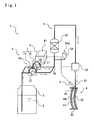
FIG. 1 is a schematic view showing an embodiment of an apparatus
for introducing a plastic raw material liquid according to the present
invention;
FIGS. 2(a) through 2(c) show an arrangement of a roller pump of the
apparatus for introducing a plastic raw material liquid according to the
present invention, FIG. 2(a) is a plan view of the roller pump of the
apparatus for introducing a plastic raw material liquid, FIG. 2(b) is a side
elevational view of a pump head of the roller pump, and FIG. 2(c) is a
graph showing fluctuations of the discharge pressure of a raw material
liquid ejected from each pump head;
FIGS. 3(a) and 3(b) are schematic views of a diaphragm pump, FIG.
3(a) showing the diaphragm pump at the time it draws in a raw material
liquid, and FIG. 3(b) the diaphragm pump at the time it discharges a raw
material liquid;
FIGS. 4(a) and 4(b) are schematic views of a plunger pump, FIG. 4(a)
showing the plunger pump at the time it draws in a raw material liquid,
and FIG. 4(b) the plunger pump at the time it discharges a raw material
liquid; and
FIG. 5 is a schematic view showing a conventional apparatus for
introducing a plastic raw material liquid.
Best Mode for Carrying out the Invention
An embodiment of a method of and an apparatus for introducing a
plastic raw material liquid according to the present invention will be
described below. However, the present invention is not limited to the
embodiment to be described below.
As shown in FIG. 1, an apparatus 1 for introducing a plastic raw
material liquid according to the present invention is an apparatus for
introducing a plastic raw material liquid 3 including a monomer mixed
with a polymerization catalyst stored in a raw material tank 2 by an
intermittent constant-rate pump 6 for drawing in and discharging the
plastic raw material liquid 3 through an inlet pipe 5 into a cavity 44 in a
casting polymerization mold 4 for casting and polymerizing a plastic lens.
The casting polymerization mold 4 has a mold member 41 for defining
an object-side surface of a plastic lens and a mold member 42 for defining
an eye-side surface of the plastic lens, the mold members 41, 42 being
positioned such that their lens molding surfaces are spaced from each
other in confronting relation, and an adhesive tape 43 wound in at least
one turn fully around outer peripheral surfaces of the mold members 41,
42, thereby sealing the gap between the mold members 41, 42 to form a
cavity 44 therebetween. The casting polymerization mold 4 also has an
inlet port 45 for introducing the plastic raw material liquid 3 therethrough.
The inlet port 45 is formed by peeling off overlapping layers of the
adhesive tape 43. Alternatively, the inlet port 45 is formed by forming a
hole, in advance, in the adhesive tape 43 at a given position. The gap
between the peripheral edges of the mold members 41, 42 of the casting
polymerization mold 4 is small when a convex lens is produced, e.g., about
1 mm. Therefore, a slender inlet nozzle 51 is used to introduce the raw
material liquid from the inlet port 45 into the cavity 44 of the casting
polymerization mold 4.
The inlet pipe 5 of the apparatus 1 for introducing a plastic raw
material liquid has a starting end positioned at the inner bottom of the
raw material tank 2. The intermittent constant-rate pump 6 is connected
to the inlet pipe 5 for drawing in the raw material liquid 3 from the raw
material tank 2 and discharging the raw material liquid 3 from the inlet
nozzle 51, which is connected to a terminal end of the inlet pipe 5, into the
cavity 44 of the casting polymerization mold 4. The inlet pipe 5 has an
inlet valve 52 connected directly to the inlet nozzle 51 for starting and
stopping delivering the raw material liquid 3 to the inlet nozzle 51. A
filter 53 and an accumulator 54 are disposed in a flow passage between the
intermittent constant-rate pump 6 and the inlet valve 52.
The intermittent constant-rate pump 6 includes a liquid delivery unit
7 for drawing in and discharging a fluid intermittently at a constant rate,
and an actuator 8 for actuating the liquid delivery unit 7. According to the
present embodiment, the intermittent constant-rate pump 6 includes a
roller pump. The roller pump, which is also referred to as a tubing pump,
has a flexible resilient tube which is progressively pressed by presser
rollers to draw in and discharge a fluid. Since the raw material liquid
flows through the tube and is kept out of direct contact with the actuator
in the roller pump, the roller pump does not allow impurities to be mixed
with the raw material liquid, and prevents the raw material liquid from
eroding the actuator.
With the apparatus 1 for introducing a plastic raw material liquid
according to the present embodiment, a roller pump 6a is of a structure
having two liquid delivery units fixed to single drive shaft and coaxially
actuatable by a single actuator. The actuator 8 includes a single drive
motor 81 and a liquid delivery unit 7 having a first pump head 7a and a
second pump head 7b which are juxtaposed and actuatable by a drive shaft
71 of the drive motor 81. Each of the pump heads 7a, 7b has three presser
rollers 72, for example, rotatably mounted at equal angular spaced
intervals on a peripheral edge of a rotary plate which is coupled to the
drive shaft 71 of the drive motor 81. A flexible resilient tube 73 that is
disposed along the peripheral edge of a stroke of the presser rollers 72 is
progressively pressed by the presser rollers 72 upon rotation of the rotary
plate that is actuated by the drive motor 81. The drive motor 81 includes a
motor whose rotational speed can be controlled for controlling the flow rate
at which the plastic raw material liquid 3 is introduced. The rotational
speed of the drive motor 81 is controlled by inverter frequency control or
servomotor control or stepping-motor control.
On the suction side of the roller pump 6a, the inlet pipe 5 is branched
into two pipes connected respectively to the suction ports of the first pump
head 7a and the second pump head 7b for supplying the raw material
liquid to the first pump head 7a and the second pump head 7b. On the
discharge side of the roller pump 6a, the branched pipes are joined to each
other by a junction 10 where the raw material liquids discharged from the
first pump head 7a and the second pump head 7b are combined with each
other.
As shown in FIG. 2(a), the first pump head 7a and the second pump
head 7b are mounted on the drive shaft 71 with their presser rollers 72
positionally staggered relatively to each other. As shown in FIG. 2(b),
each of the first pump head 7a and the second pump head 7b has three
presser rollers 72 mounted at respective positions that are radially spaced
from the center of rotation and angularly spaced at equal angles of 120°.
The presser rollers 72 of the second pump head 7b which are indicated by
the broken lines are fixed to the drive shaft 71 at positions that are
angularly spaced 60° from the presser rollers 72 of the first pump head 7a.
Therefore, as shown in FIG. 2(b), each of the presser rollers 72 of the
second pump head 7b which are indicated by the broken lines is located
intermediate between two of the presser rollers 72 of the first pump head
7a.
At each of a discharge outlet A of the first pump head 7a and a
discharge outlet B of the second pump head 7b as shown in FIG. 2(a), the
discharge pressure p has a pulsating waveform where the discharge
pressure periodically varies from zero to a certain discharge pressure level
with time t as shown in FIG. 2(c). The pulsating waveforms of the
discharge pressures at the discharge outlets A, B are one-half out of phase
with each other, so that at the time one discharge pressure level is
minimum, the other discharge pressure level is maximum. Therefore, at a
position C where the outlets A, B are combined with each other, as shown
at C in FIG. 2(c), the combined pulsating waveforms interfere with each
other, reducing the difference between maximum and minimum pressures.
That is, the discharge pressure is averaged, reducing pulsations.
As a result, when the plastic raw material liquid 3 is discharged at
different times from the juxtaposed liquid delivery units 7a, 7b, and the
flows of the plastic raw material liquid 3 that are discharged from the
juxtaposed liquid delivery units 7a, 7b are combined and introduced from
the inlet nozzle 51 into the casting polymerization mold 4, the flow rate of
the plastic raw material liquid 3 discharged from the inlet nozzle 51 is
averaged to prevent air bubbles from being trapped into the plastic raw
material liquid 3. Therefore, the generation of an air bubble defect is
reduced to increase production yield.
Since the first pump head 7a and the second pump head 7b are
disposed parallel to each other, the rotational speed of the drive shaft 71 of
the drive motor 81 may be set to a value lower than the conventional
rotational speed for achieving a predetermined flow rate. Tubes 73 that
are used in the roller pump 6a are subject to repeated compressive
deformation and hence are susceptible to rupture when used over a long
period of time. Because the rotational speed of the drive shaft 71 of the
roller pump 6a can be set to a lower value, a repeated load imposed on the
tubes 73 is reduced, allowing the tubes 73 to be used for an extended
period of time. Therefore, the danger of damage to the tubes 73 and hence
a leakage of the raw material liquid can be avoided even when used over a
long period of time.
The first pump head 7a and the second pump head 7b, which are
juxtaposed, of the liquid delivery unit 7 are fixedly mounted on the single
drive shaft 71, and are simultaneously driven by the single drive shaft 71
to keep the presser rollers 72 in their relative positions. Therefore, the
timing to draw in and discharge the plastic raw material liquid 3 is not
varied with time, but the discharge of the plastic row material liquid 3 is
stably averaged.
The accumulator 54 contains a fluid whose volume is variable
depending on the pressure of a fluid. The accumulator 54 has an air
chamber 54a defined in a tank and providing an interface with the liquid
communicating with the inlet pipe 5. The air chamber 54a of the
accumulator 54 serves as a damper, and is shrunk when under a high
pressure and expanded when under a low pressure. The accumulator 54 is
connected to the inlet pipe 5 between the intermittent constant-rate pump
6 and the inlet nozzle 51 for absorbing pulsations to average the discharge
pressure. As the air chamber 54a is larger, the pulsation reducing ability
is greater. For controlling the flow rate of the plastic row material liquid 3
to be introduced, the volume of the air chamber 54a needs to be managed
in a range from 0.1 ml to 10 ml, or preferably from 0.5 ml to 3.0 ml. If the
air chamber 54a is too large, then the response is reduced when the flow
rate is changed. If the flow rate is to be changed instantaneously, then the
air chamber 54a is required to be reduced in size. The air chamber 54a
may be forcibly formed in the vent of a capsule filter or a cartridge filter of
the filter 53. For managing the air chamber in the filter 53, it is important
to direct the plastic raw material liquid 3 to flow upwardly in order to
allow air to be released easily from the filter 53. The accumulator 54 itself
may be made of a resilient material and may be free of an air chamber to
achieve the same advantages.
The filter 53 serves to trap fine foreign matter in the raw material
liquid. When the raw material liquid 3 passes through the filter 53, the
filter 53 causes a pressure loss and increases the resistance of the flow
passage to the flow of the raw material liquid 3. The filter 53 that is
connected in series to the inlet pipe 5 between the intermittent constant-rate
pump 6 and the inlet nozzle 51 is effective to absorb pulsations and
average the discharge pressure. Since a disk filter having a small filter
area is not effective enough to lower pulsations of the discharge pressure,
a capsule filter or a cartridge filter having a large filter area is preferable
for use as the filter 53.
The apparatus 1 for introducing a plastic raw material liquid
according to the present embodiment has a fill detecting means for
detecting the plastic raw material liquid 3 that overflows the inlet port 45
when the cavity 44 is filled with the plastic raw material liquid 3. The fill
detecting means includes a vacuum suction nozzle 9 having a tip end
disposed near the inlet port 45 of the casting polymerization mold 4. The
vacuum suction nozzle 9 draws in the plastic raw material liquid 3 that
overflows the inlet port 45 and a sensor disposed in a vacuum suction
circuit detects the plastic raw material liquid 3 drawn by the vacuum
suction nozzle 9, whereupon the fill detecting means detects when the
cavity 44 is filled with the plastic raw material liquid 3. In response to a
signal from the fill detecting means, a control system (not shown) deenergizes
the drive motor 81 of the roller pump 6a and simultaneously
closes the inlet valve 52. When the drive shaft 71 of the roller pump 6a is
stopped against rotation, the supply of the plastic raw material liquid 3 is
stopped. The inlet valve 52 is used to prevent the plastic raw material
liquid 3 from dripping from the inlet nozzle 51.
The non-illustrated control system controls the rotational speed of the
roller pump drive motor 81 to control the flow rate of the plastic raw
material liquid 3 to be introduced. Because the casting polymerization
mold 4 is available in many types having greatly different volumes, it is
preferable to control the flow rate of the plastic raw material liquid 3 to be
introduced depending on the volume of the casting polymerization mold 4
in order to complete the process of filling the casting polymerization mold
4 with the plastic raw material liquid 3 within a predetermined period of
time. If the flow rate is high the instant the casting polymerization mold 4
is filled with the plastic raw material liquid 3, then the plastic raw
material liquid 3 tends to spill over, it is preferable to employ such an
introducing pattern that the flow rate is reduced immediately before the
casting polymerization mold 4 is filled. It is also preferable to perform a
control process for slowly increasing the rotational speed of the drive
motor 81 to lessen the momentum of the plastic raw material liquid 3 at
the time it impinges upon the mold in an initial introducing stage.
Operation of the apparatus 1 for introducing a plastic raw material
liquid shown in FIG. 1 will be described below. The inlet nozzle 51 is
installed on the tip end of the inlet valve 52, and the tip end of the inlet
nozzle 51 is inserted into the inlet port 45 which is formed in advance in
the adhesive tape 43 of the casting polymerization mold 4. The roller
pump 6a is actuated to introduce the plastic material liquid 3 in advance
prepared in the raw material tank 2 from the inlet nozzle 51 through the
inlet port 45 into the cavity 44 of the casting polymerization mold 4 while
the rotational speed of the drive motor 81 of the roller pump 6a is being
controlled according to a programmed pattern or depending on a signal
from a liquid level sensor disposed in the casting polymerization mold 4.
When the casting polymerization mold 4 is filled with the plastic material
liquid 3 supplied, the plastic material liquid 3 overflows the inlet port 45
and is drawn by the vacuum suction nozzle 9. The plastic material liquid
3 that has overflowed the inlet port 45 is detected by the sensor disposed
in the vacuum suction circuit. In response to a signal from the sensor, the
roller pump 6a is stopped and the inlet valve 52 is closed simultaneously.
In FIGS. 1 and 2, the roller pump 6a is employed which has single
drive shaft 71 driven by the single drive motor 81 for coaxially actuating
two pump heads 7a, 7b of the liquid delivery unit 7. If the number of
pump heads is increased and their operation is brought slightly out of
phase with each other, then they are effective to reduce pulsations of the
discharge pressure. However, since they make the inlet pipe 5 complex,
make it difficult to clean the inlet pipe 5, and increase the cost of the
apparatus, the number of pump heads should preferably be 2 or 3. The
number of presser rollers 72 and the angular intervals therebetween are
not limited. A plurality of roller pumps each having a single liquid
delivery unit actuatable by a single actuator may be provided and the
liquid delivery assemblies may be operated to draw and discharge the raw
material liquid at different times. From the standpoint of the ease of
control and an energy saving ability, however, it is preferable to use a
roller pump having a plurality of pump heads actuatable by a single drive
motor. The maximum flow rate at which the raw material liquid is
introduced into the casting polymerization mold is already determined,
and simply installing a plurality of pump heads results in an increase in
the flow rate at which the raw material liquid is discharged therefrom.
Accordingly, the desired flow rate is achieved by reducing the rotational
speed of the drive shaft.
The apparatus for introducing a plastic raw material liquid according
to the above embodiment employs the roller pump as the intermittent
constant-rate pump 6. However, instead of the roller pump, a diaphragm
pump or a plunger pump may be used as the intermittent constant-rate
pump.
FIGS. 3(a) and 3(b) schematically show a structure of a diaphragm
pump. The diaphragm pump has a liquid delivery unit including a thin
film (diaphragm) made of a resilient material which changes its shape to
move back and forth for drawing and discharging the raw material liquid.
The diaphragm may be actuated under a hydraulic or pneumatic pressure,
mechanically back and forth by a plunger, or by a piezoelectric element.
The diaphragm pump shown in FIGS. 3(a) and 3(b) is actuated by
piezoelectric elements.
The diaphragm pump 6b which is actuated by piezoelectric elements
uses a diaphragm 61 incorporating two piezoelectric elements. When a
voltage is applied to the diaphragm 61, one of the piezoelectric elements is
elongated and the other piezoelectric element is contracted. The
diaphragm 61 is disposed in a space within a pressure vessel which has a
suction port 62 and a discharge port 63, dividing the space into a first
space 64 connected to the suction port 62 and the discharge port 63 and a
second space 65 separate from the first space 64. The suction port 62 has
a check valve 62a which is opened under a negative pressure in the
pressure vessel, and the discharge port 63 has a check valve 63a which is
opened under a pressure buildup in the pressure vessel.
When an AC voltage is applied to the diaphragm 61, the diaphragm
61 vibrates in the periodic cycles of the AC voltage. The amount of the raw
material liquid to be introduced is controlled by changing the voltage to
control the amplitude of the diaphragm 61 or changing the frequency to
control the frequency of vibrations of the diaphragm 61.
As shown in FIG. 3(a), when the diaphragm 61 is deformed into the
second space 65, a negative pressure is developed in the first space 64,
opening the check valve 62a in the inlet port 62 and closing the check
valve 63a in the discharge port 63, thereby causing the fluid to flow from
the inlet port 62 into the first space 64. Then, as shown in FIG. 3(b), when
the diaphragm 61 is deformed into the first space 64, a pressure buildup is
developed in the first space 64, closing the check valve 62a in the inlet port
62 and opening the check valve 63a in the discharge port 63, thereby
discharging the fluid in the first space 64 from the discharge port 63.
Since the diaphragm pump 6b draws in and discharges the fluid on the
vibration of the diaphragm 61, the discharge pressure has pulsations.
Pulsations caused by the diaphragm pump 6b in the discharge
pressure of the plastic raw material liquid can be reduced by connecting a
plurality of diaphragm pumps 6b parallel to each other and vibrating the
diaphragms 61 thereof at different times to cause fluid flows discharged
from the diaphragm pumps 6b to interfere with each other when they are
combined. If the diaphragms are moved mechanically back and forth, then
the diaphragms can be actuated by a single drive shaft. The diaphragm
pumps 6b which employ piezoelectric elements may have their diaphragms
61 vibrated at different times by applying control voltages from a
piezoelectric controller out of phase with each other.
FIGS. 4(a) and 4(b) schematically show a plunger pump. The plunger
pump is a pump for moving back and forth a plunger in the shape of a
round rod within a cylinder to change the volume of the cylinder to draw
in and discharge the fluid. The plunger pump 6c has a plunger 67 movable
back and forth in a cylinder 66. A suction port 68 and a discharge port 69
are connected to the cylinder 66. The suction port 68 has a check valve
68a which is opened under a negative pressure in the cylinder 66, and the
discharge port 69 has a check valve 69a which is opened under a pressure
buildup in the cylinder 66.
As shown in FIG. 4(a), when the plunger 67 is pulled, a negative
pressure is developed in the cylinder 66, opening the check valve 68a in
the inlet port 68 and closing the check valve 69a in the discharge port 69,
thereby causing the fluid to be drawn in from the inlet port 68. Then, as
shown in FIG. 4(b), when the plunger 67 is pushed, the fluid in the
cylinder 66 is forced out. At this time, the check valve 68a in the inlet port
68 is closed, and the check valve 69a in the discharge port 69 is opened. In
response to a signal from a plunger controller, the plunger 67 is repeatedly
pulled and pushed. Therefore the discharge pressure of the fluid has
pulsations.
Pulsations caused by the plunger pump can be reduced by connecting
a plurality of plunger pump liquid delivery units parallel to each other and
operating the plungers 67 at different times to cause fluid flows discharged
from the liquid delivery units to interfere with each other when they are
combined. The plungers may be actuated to move back and forth by a
single drive shaft. The amount of the raw material liquid to be introduced
by the plunger pump is controlled by changing the moving stroke of the
plunger or changing the operating periodic cycles of the plunger with a
plunger controller.
The present invention is not limited to the above embodiments. In
the above description, the casting polymerization mold is used to mold a
plastic lens. However, the present invention is applicable to not only
casting polymerization molds for molding plastic lenses, but also any
casting polymerization molds. Three pumps, i.e., the roller pump, the
diaphragm pump, and the plunger pump, are described as the intermittent
constant-rate pump. However, other constant-rate pumps which produce
pressure pulsations can also be used. An intermittent constant-rate pump
having a plurality of liquid delivery units actuatable by a single actuator
and an intermittent constant-rate pump having a single liquid delivery
unit actuatable by a single actuator may be combined with each other, or
intermittent constant-rate pumps of different types may be combined with
each other, insofar as the liquid delivery units connected parallel to each
other can draw in and discharge the fluid at different times.
(Example)
An inventive example according to the present invention will be
described below. A roller pump having a pump head with three presser
rolls angularly spaced at equal angles of 120° was used as an intermittent
constant-rate pump. A single pump head and two pump heads were
compared with each other. With the two pump heads, the presser rollers
thereof were fixedly mounted on the drive shaft such that each presser
roller of one pump head was positioned between two adjacent presser
rollers of the other pump head. A capsule filter was disposed in a pipe
downstream of the roller pump. An accumulator had an air chamber of 1
ml in the vent of the capsule filter. A combination of the above three
pulsation reducing means and the generation of air bubbles at the time the
plastic raw material liquid is introduced into the casting polymerization
mold are shown in Table 1. Air bubble generation percentages represent
whether air bubbles are present or not when the plastic raw material
liquid is introduced, but not the values of air bubble defects after the
plastic raw material liquid is cured by heat or ultraviolet rays.
| Pump head | One | Two |
| Filter | None | Yes | None | Yes |
| Accumulator | None | Yes | None | Yes | None | Yes | None | Yes |
| Air bubble generation percentage (%) | 70 | 12 | 16 | 5 | 3.2 | 0.2 | 0.8 | 0.0 |
As can be seen from Table 1, air bubbles were generated at 70% under
conditions of one pump head, no filter, and no accumulator (conventional
introducing method), and the air bubble generation percentage was 0%
when the three pulsation reducing means were combined. It was proven
that the inventive introducing method was highly effective to reduce
pulsations and suppress the generation of air bubbles upon introduction of
the plastic raw material liquid. Respective operation of pulsation reducing
means are also effective.
Industrial applicability
The method of and the apparatus for introducing a plastic raw
material liquid according to the present invention can be used in
applications for introducing the plastic raw material liquid into a cast
polymerization mold in a casting and polymerizing step of a process of
producing a plastic eyeglass lens, for example.