EP1541191B1 - Micro integrated cardiac pacemaker - Google Patents
Micro integrated cardiac pacemaker Download PDFInfo
- Publication number
- EP1541191B1 EP1541191B1 EP03766728A EP03766728A EP1541191B1 EP 1541191 B1 EP1541191 B1 EP 1541191B1 EP 03766728 A EP03766728 A EP 03766728A EP 03766728 A EP03766728 A EP 03766728A EP 1541191 B1 EP1541191 B1 EP 1541191B1
- Authority
- EP
- European Patent Office
- Prior art keywords
- information
- cardiac pacemaker
- miniature integrated
- ultra miniature
- integrated cardiac
- Prior art date
- Legal status (The legal status is an assumption and is not a legal conclusion. Google has not performed a legal analysis and makes no representation as to the accuracy of the status listed.)
- Expired - Lifetime
Links
- 230000000747 cardiac effect Effects 0.000 title claims abstract description 100
- 239000000446 fuel Substances 0.000 claims abstract description 72
- 210000004369 blood Anatomy 0.000 claims abstract description 24
- 239000008280 blood Substances 0.000 claims abstract description 24
- 210000001124 body fluid Anatomy 0.000 claims abstract description 23
- 239000010839 body fluid Substances 0.000 claims abstract description 23
- 230000001590 oxidative effect Effects 0.000 claims abstract description 20
- 108090000790 Enzymes Proteins 0.000 claims abstract description 18
- 102000004190 Enzymes Human genes 0.000 claims abstract description 18
- QVGXLLKOCUKJST-UHFFFAOYSA-N atomic oxygen Chemical compound [O] QVGXLLKOCUKJST-UHFFFAOYSA-N 0.000 claims abstract description 18
- 239000001301 oxygen Substances 0.000 claims abstract description 18
- 229910052760 oxygen Inorganic materials 0.000 claims abstract description 18
- 238000006243 chemical reaction Methods 0.000 claims abstract description 13
- 239000008151 electrolyte solution Substances 0.000 claims abstract description 11
- 210000004165 myocardium Anatomy 0.000 claims abstract description 7
- 230000001746 atrial effect Effects 0.000 claims abstract description 6
- 230000004936 stimulating effect Effects 0.000 claims description 23
- 210000005003 heart tissue Anatomy 0.000 claims description 10
- 230000002861 ventricular Effects 0.000 abstract description 2
- 238000010586 diagram Methods 0.000 description 17
- 229940088598 enzyme Drugs 0.000 description 16
- 230000000638 stimulation Effects 0.000 description 14
- 238000004891 communication Methods 0.000 description 12
- 238000002513 implantation Methods 0.000 description 7
- 238000000034 method Methods 0.000 description 7
- CURLTUGMZLYLDI-UHFFFAOYSA-N Carbon dioxide Chemical compound O=C=O CURLTUGMZLYLDI-UHFFFAOYSA-N 0.000 description 6
- WQZGKKKJIJFFOK-GASJEMHNSA-N Glucose Natural products OC[C@H]1OC(O)[C@H](O)[C@@H](O)[C@@H]1O WQZGKKKJIJFFOK-GASJEMHNSA-N 0.000 description 6
- 230000008859 change Effects 0.000 description 6
- 239000000284 extract Substances 0.000 description 6
- 239000008103 glucose Substances 0.000 description 6
- -1 glucose) Chemical class 0.000 description 5
- 239000003054 catalyst Substances 0.000 description 4
- 230000002950 deficient Effects 0.000 description 4
- PCHJSUWPFVWCPO-UHFFFAOYSA-N gold Chemical compound [Au] PCHJSUWPFVWCPO-UHFFFAOYSA-N 0.000 description 4
- 229910052737 gold Inorganic materials 0.000 description 4
- 239000010931 gold Substances 0.000 description 4
- BASFCYQUMIYNBI-UHFFFAOYSA-N platinum Chemical compound [Pt] BASFCYQUMIYNBI-UHFFFAOYSA-N 0.000 description 4
- 230000017531 blood circulation Effects 0.000 description 3
- 229910002092 carbon dioxide Inorganic materials 0.000 description 3
- 239000001569 carbon dioxide Substances 0.000 description 3
- 230000002503 metabolic effect Effects 0.000 description 3
- 239000002207 metabolite Substances 0.000 description 3
- 235000000346 sugar Nutrition 0.000 description 3
- 150000008163 sugars Chemical class 0.000 description 3
- 210000000779 thoracic wall Anatomy 0.000 description 3
- 241000157855 Cinchona Species 0.000 description 2
- 235000001258 Cinchona calisaya Nutrition 0.000 description 2
- SRBFZHDQGSBBOR-IOVATXLUSA-N D-xylopyranose Chemical compound O[C@@H]1COC(O)[C@H](O)[C@H]1O SRBFZHDQGSBBOR-IOVATXLUSA-N 0.000 description 2
- 108010050375 Glucose 1-Dehydrogenase Proteins 0.000 description 2
- SXRSQZLOMIGNAQ-UHFFFAOYSA-N Glutaraldehyde Chemical compound O=CCCCC=O SXRSQZLOMIGNAQ-UHFFFAOYSA-N 0.000 description 2
- LOUPRKONTZGTKE-WZBLMQSHSA-N Quinine Chemical compound C([C@H]([C@H](C1)C=C)C2)C[N@@]1[C@@H]2[C@H](O)C1=CC=NC2=CC=C(OC)C=C21 LOUPRKONTZGTKE-WZBLMQSHSA-N 0.000 description 2
- 230000009471 action Effects 0.000 description 2
- PYMYPHUHKUWMLA-UHFFFAOYSA-N arabinose Natural products OCC(O)C(O)C(O)C=O PYMYPHUHKUWMLA-UHFFFAOYSA-N 0.000 description 2
- SRBFZHDQGSBBOR-UHFFFAOYSA-N beta-D-Pyranose-Lyxose Natural products OC1COC(O)C(O)C1O SRBFZHDQGSBBOR-UHFFFAOYSA-N 0.000 description 2
- WQZGKKKJIJFFOK-VFUOTHLCSA-N beta-D-glucose Chemical compound OC[C@H]1O[C@@H](O)[C@H](O)[C@@H](O)[C@@H]1O WQZGKKKJIJFFOK-VFUOTHLCSA-N 0.000 description 2
- 230000005540 biological transmission Effects 0.000 description 2
- 150000001720 carbohydrates Chemical class 0.000 description 2
- 235000014633 carbohydrates Nutrition 0.000 description 2
- 239000011248 coating agent Substances 0.000 description 2
- 238000000576 coating method Methods 0.000 description 2
- 230000006870 function Effects 0.000 description 2
- 229910052739 hydrogen Inorganic materials 0.000 description 2
- 239000001257 hydrogen Substances 0.000 description 2
- GPRLSGONYQIRFK-UHFFFAOYSA-N hydron Chemical class [H+] GPRLSGONYQIRFK-UHFFFAOYSA-N 0.000 description 2
- 239000007943 implant Substances 0.000 description 2
- 239000000203 mixture Substances 0.000 description 2
- 229910052697 platinum Inorganic materials 0.000 description 2
- 238000001228 spectrum Methods 0.000 description 2
- 239000000126 substance Substances 0.000 description 2
- XLYOFNOQVPJJNP-UHFFFAOYSA-N water Substances O XLYOFNOQVPJJNP-UHFFFAOYSA-N 0.000 description 2
- ZQXIMYREBUZLPM-UHFFFAOYSA-N 1-aminoethanethiol Chemical compound CC(N)S ZQXIMYREBUZLPM-UHFFFAOYSA-N 0.000 description 1
- ZIUYHTQZEPDUCZ-UHFFFAOYSA-N 7h-pyrrolo[2,3-h]quinoline Chemical compound C1=CN=C2C(C=CN3)=C3C=CC2=C1 ZIUYHTQZEPDUCZ-UHFFFAOYSA-N 0.000 description 1
- 102000009027 Albumins Human genes 0.000 description 1
- 108010088751 Albumins Proteins 0.000 description 1
- 206010049765 Bradyarrhythmia Diseases 0.000 description 1
- FBPFZTCFMRRESA-KVTDHHQDSA-N D-Mannitol Chemical compound OC[C@@H](O)[C@@H](O)[C@H](O)[C@H](O)CO FBPFZTCFMRRESA-KVTDHHQDSA-N 0.000 description 1
- PHOQVHQSTUBQQK-SQOUGZDYSA-N D-glucono-1,5-lactone Chemical compound OC[C@H]1OC(=O)[C@H](O)[C@@H](O)[C@@H]1O PHOQVHQSTUBQQK-SQOUGZDYSA-N 0.000 description 1
- 229930091371 Fructose Natural products 0.000 description 1
- 239000005715 Fructose Substances 0.000 description 1
- RFSUNEUAIZKAJO-ARQDHWQXSA-N Fructose Chemical compound OC[C@H]1O[C@](O)(CO)[C@@H](O)[C@@H]1O RFSUNEUAIZKAJO-ARQDHWQXSA-N 0.000 description 1
- 108010015776 Glucose oxidase Proteins 0.000 description 1
- 239000004366 Glucose oxidase Substances 0.000 description 1
- 108010020056 Hydrogenase Proteins 0.000 description 1
- 108010029541 Laccase Proteins 0.000 description 1
- WHXSMMKQMYFTQS-UHFFFAOYSA-N Lithium Chemical compound [Li] WHXSMMKQMYFTQS-UHFFFAOYSA-N 0.000 description 1
- 229930195725 Mannitol Natural products 0.000 description 1
- 108090000854 Oxidoreductases Proteins 0.000 description 1
- 102000004316 Oxidoreductases Human genes 0.000 description 1
- 206010040893 Skin necrosis Diseases 0.000 description 1
- CZMRCDWAGMRECN-UGDNZRGBSA-N Sucrose Chemical compound O[C@H]1[C@H](O)[C@@H](CO)O[C@@]1(CO)O[C@@H]1[C@H](O)[C@@H](O)[C@H](O)[C@@H](CO)O1 CZMRCDWAGMRECN-UGDNZRGBSA-N 0.000 description 1
- 229930006000 Sucrose Natural products 0.000 description 1
- 206010058990 Venous occlusion Diseases 0.000 description 1
- QOJVPCDYXUQNMD-UHFFFAOYSA-N [[5-(6-aminopurin-9-yl)-4-hydroxy-3-phosphonooxyoxolan-2-yl]methoxy-hydroxyphosphoryl] [5-(7,8-dimethyl-2,4-dioxobenzo[g]pteridin-10-yl)-2,3,4-trihydroxypentyl] hydrogen phosphate Chemical compound C1=NC2=C(N)N=CN=C2N1C(C(O)C1OP(O)(O)=O)OC1COP(O)(=O)OP(O)(=O)OCC(O)C(O)C(O)CN1C2=NC(=O)NC(=O)C2=NC2=C1C=C(C)C(C)=C2 QOJVPCDYXUQNMD-UHFFFAOYSA-N 0.000 description 1
- 125000003277 amino group Chemical group 0.000 description 1
- PYMYPHUHKUWMLA-WDCZJNDASA-N arabinose Chemical compound OC[C@@H](O)[C@@H](O)[C@H](O)C=O PYMYPHUHKUWMLA-WDCZJNDASA-N 0.000 description 1
- 230000036772 blood pressure Effects 0.000 description 1
- 230000036760 body temperature Effects 0.000 description 1
- 208000006218 bradycardia Diseases 0.000 description 1
- 210000004375 bundle of his Anatomy 0.000 description 1
- 210000000038 chest Anatomy 0.000 description 1
- LOUPRKONTZGTKE-UHFFFAOYSA-N cinchonine Natural products C1C(C(C2)C=C)CCN2C1C(O)C1=CC=NC2=CC=C(OC)C=C21 LOUPRKONTZGTKE-UHFFFAOYSA-N 0.000 description 1
- 239000005515 coenzyme Substances 0.000 description 1
- 238000007796 conventional method Methods 0.000 description 1
- 238000001514 detection method Methods 0.000 description 1
- 150000002016 disaccharides Chemical class 0.000 description 1
- 210000001174 endocardium Anatomy 0.000 description 1
- 235000012209 glucono delta-lactone Nutrition 0.000 description 1
- 229960003681 gluconolactone Drugs 0.000 description 1
- 229940116332 glucose oxidase Drugs 0.000 description 1
- 235000019420 glucose oxidase Nutrition 0.000 description 1
- 230000013632 homeostatic process Effects 0.000 description 1
- 150000002500 ions Chemical class 0.000 description 1
- 229910052744 lithium Inorganic materials 0.000 description 1
- 239000000594 mannitol Substances 0.000 description 1
- 235000010355 mannitol Nutrition 0.000 description 1
- 230000007246 mechanism Effects 0.000 description 1
- 230000004048 modification Effects 0.000 description 1
- 238000012986 modification Methods 0.000 description 1
- 238000012544 monitoring process Methods 0.000 description 1
- 150000002772 monosaccharides Chemical class 0.000 description 1
- 230000002107 myocardial effect Effects 0.000 description 1
- 230000007935 neutral effect Effects 0.000 description 1
- 229910052762 osmium Inorganic materials 0.000 description 1
- SYQBFIAQOQZEGI-UHFFFAOYSA-N osmium atom Chemical compound [Os] SYQBFIAQOQZEGI-UHFFFAOYSA-N 0.000 description 1
- 230000003647 oxidation Effects 0.000 description 1
- 238000007254 oxidation reaction Methods 0.000 description 1
- 150000002972 pentoses Chemical class 0.000 description 1
- 238000000718 qrs complex Methods 0.000 description 1
- 229960000948 quinine Drugs 0.000 description 1
- 125000003410 quininyl group Chemical group 0.000 description 1
- 230000009467 reduction Effects 0.000 description 1
- 230000004044 response Effects 0.000 description 1
- 230000033764 rhythmic process Effects 0.000 description 1
- 238000007789 sealing Methods 0.000 description 1
- 239000000758 substrate Substances 0.000 description 1
- 239000005720 sucrose Substances 0.000 description 1
- 208000024891 symptom Diseases 0.000 description 1
- 210000001519 tissue Anatomy 0.000 description 1
- 238000012546 transfer Methods 0.000 description 1
- 238000002604 ultrasonography Methods 0.000 description 1
Images


Classifications
-
- A—HUMAN NECESSITIES
- A61—MEDICAL OR VETERINARY SCIENCE; HYGIENE
- A61N—ELECTROTHERAPY; MAGNETOTHERAPY; RADIATION THERAPY; ULTRASOUND THERAPY
- A61N1/00—Electrotherapy; Circuits therefor
- A61N1/18—Applying electric currents by contact electrodes
- A61N1/32—Applying electric currents by contact electrodes alternating or intermittent currents
- A61N1/36—Applying electric currents by contact electrodes alternating or intermittent currents for stimulation
- A61N1/372—Arrangements in connection with the implantation of stimulators
- A61N1/37211—Means for communicating with stimulators
- A61N1/37252—Details of algorithms or data aspects of communication system, e.g. handshaking, transmitting specific data or segmenting data
- A61N1/37288—Communication to several implantable medical devices within one patient
-
- A—HUMAN NECESSITIES
- A61—MEDICAL OR VETERINARY SCIENCE; HYGIENE
- A61N—ELECTROTHERAPY; MAGNETOTHERAPY; RADIATION THERAPY; ULTRASOUND THERAPY
- A61N1/00—Electrotherapy; Circuits therefor
- A61N1/18—Applying electric currents by contact electrodes
- A61N1/32—Applying electric currents by contact electrodes alternating or intermittent currents
- A61N1/36—Applying electric currents by contact electrodes alternating or intermittent currents for stimulation
- A61N1/362—Heart stimulators
- A61N1/365—Heart stimulators controlled by a physiological parameter, e.g. heart potential
- A61N1/36507—Heart stimulators controlled by a physiological parameter, e.g. heart potential controlled by gradient or slope of the heart potential
-
- A—HUMAN NECESSITIES
- A61—MEDICAL OR VETERINARY SCIENCE; HYGIENE
- A61N—ELECTROTHERAPY; MAGNETOTHERAPY; RADIATION THERAPY; ULTRASOUND THERAPY
- A61N1/00—Electrotherapy; Circuits therefor
- A61N1/18—Applying electric currents by contact electrodes
- A61N1/32—Applying electric currents by contact electrodes alternating or intermittent currents
- A61N1/36—Applying electric currents by contact electrodes alternating or intermittent currents for stimulation
- A61N1/362—Heart stimulators
- A61N1/365—Heart stimulators controlled by a physiological parameter, e.g. heart potential
- A61N1/368—Heart stimulators controlled by a physiological parameter, e.g. heart potential comprising more than one electrode co-operating with different heart regions
-
- A—HUMAN NECESSITIES
- A61—MEDICAL OR VETERINARY SCIENCE; HYGIENE
- A61N—ELECTROTHERAPY; MAGNETOTHERAPY; RADIATION THERAPY; ULTRASOUND THERAPY
- A61N1/00—Electrotherapy; Circuits therefor
- A61N1/18—Applying electric currents by contact electrodes
- A61N1/32—Applying electric currents by contact electrodes alternating or intermittent currents
- A61N1/36—Applying electric currents by contact electrodes alternating or intermittent currents for stimulation
- A61N1/372—Arrangements in connection with the implantation of stimulators
- A61N1/375—Constructional arrangements, e.g. casings
- A61N1/3756—Casings with electrodes thereon, e.g. leadless stimulators
-
- A—HUMAN NECESSITIES
- A61—MEDICAL OR VETERINARY SCIENCE; HYGIENE
- A61N—ELECTROTHERAPY; MAGNETOTHERAPY; RADIATION THERAPY; ULTRASOUND THERAPY
- A61N1/00—Electrotherapy; Circuits therefor
- A61N1/18—Applying electric currents by contact electrodes
- A61N1/32—Applying electric currents by contact electrodes alternating or intermittent currents
- A61N1/36—Applying electric currents by contact electrodes alternating or intermittent currents for stimulation
- A61N1/372—Arrangements in connection with the implantation of stimulators
- A61N1/378—Electrical supply
- A61N1/3785—Electrical supply generated by biological activity or substance, e.g. body movement
-
- H—ELECTRICITY
- H01—ELECTRIC ELEMENTS
- H01M—PROCESSES OR MEANS, e.g. BATTERIES, FOR THE DIRECT CONVERSION OF CHEMICAL ENERGY INTO ELECTRICAL ENERGY
- H01M8/00—Fuel cells; Manufacture thereof
- H01M8/16—Biochemical fuel cells, i.e. cells in which microorganisms function as catalysts
-
- A—HUMAN NECESSITIES
- A61—MEDICAL OR VETERINARY SCIENCE; HYGIENE
- A61N—ELECTROTHERAPY; MAGNETOTHERAPY; RADIATION THERAPY; ULTRASOUND THERAPY
- A61N1/00—Electrotherapy; Circuits therefor
- A61N1/18—Applying electric currents by contact electrodes
- A61N1/32—Applying electric currents by contact electrodes alternating or intermittent currents
- A61N1/36—Applying electric currents by contact electrodes alternating or intermittent currents for stimulation
- A61N1/372—Arrangements in connection with the implantation of stimulators
- A61N1/37205—Microstimulators, e.g. implantable through a cannula
-
- Y—GENERAL TAGGING OF NEW TECHNOLOGICAL DEVELOPMENTS; GENERAL TAGGING OF CROSS-SECTIONAL TECHNOLOGIES SPANNING OVER SEVERAL SECTIONS OF THE IPC; TECHNICAL SUBJECTS COVERED BY FORMER USPC CROSS-REFERENCE ART COLLECTIONS [XRACs] AND DIGESTS
- Y02—TECHNOLOGIES OR APPLICATIONS FOR MITIGATION OR ADAPTATION AGAINST CLIMATE CHANGE
- Y02E—REDUCTION OF GREENHOUSE GAS [GHG] EMISSIONS, RELATED TO ENERGY GENERATION, TRANSMISSION OR DISTRIBUTION
- Y02E60/00—Enabling technologies; Technologies with a potential or indirect contribution to GHG emissions mitigation
- Y02E60/30—Hydrogen technology
- Y02E60/50—Fuel cells
Definitions
- the present invention concerns an ultra miniature integrated cardiac pacemaker and distributed cardiac pacing system.
- the invention provides an ultra miniature integrated cardiac pacemaker and distributed cardiac pacing system that allows pacing of the heart without the need for conventional lead wires that connect the electrodes and the main body of the pacemaker, and allows implantation by catheter manipulation without incising the chest wall, which avoids imposing an extra burden on the user.
- ultra miniature refers to the minute size of the pacemaker to the extent that it can be attached to the tip of a catheter.
- a cardiac pacemaker is a device that controls the rhythm of the heart by delivering electrical impulses to the heart, and is indicated for use in patients with symptoms of bradyarrhythmia.
- a conventional cardiac pacemaker includes the main body of the cardiac pacemaker (generator), lead wires, and electrodes that transmit a stimulating pulse to the myocardium.
- the main body of the cardiac pacemaker and the electrodes are connected by lead wires.
- conventional pacemakers have the following problems.
- a shift in position of the electrodes may cause defective pacing.
- a second operation has to be performed, which adds extra strain for the patient.
- a cardiac pacemaker in which the signals for cardiac stimulation are delivered from the cardiac pacemaker main body to the stimulation electrodes by wireless transmission, thus eliminating the lead wires between the cardiac pacemaker main body and the electrodes.
- the present invention was developed in order to solve the above problems, and to provide an ultra miniature integrated cardiac pacemaker and distributed cardiac pacing system with the following features: the generator function of electric stimulus by the pacemaker main body is integrated with the electrodes, thus allowing pacing of the heart without the need for conventional lead wires connecting the electrodes and pacemaker main body. By integrating the control unit of the pacemaker main body and the electrodes, there is no need to implant the pacemaker main body, which avoids imposing an extra burden on the user.
- EP 0443496 discloses an implantable heart pacemaker including means for monitoring electrical signals generated by the heart and for producing a corresponding electrocardiogram signal in order to stimulate the heart by stimulation means.
- GB 1422171 discloses a fuel cell using an oxidisable organic substance and oxygen both from a body fluid which may be used for the operation of heart pacemakers.
- the invention is set out in claim 1.
- the ultra miniature integrated cardiac pacemaker of the present invention requires no chest incision, and is implanted in the heart by attaching it to the tip of a catheter and extracting the catheter after implanting.
- the pacemaker includes a control unit that outputs control signals, a heart stimulating means that responds to the control signal and electrically stimulates the heart tissue, an electrocardiographic information detecting means that detects the electrocardiographic information and outputs it to the control unit, and a power unit that supplies the driving power.
- the control unit outputs the control signals based on electrocardiographic information.
- the power unit is preferably a biological fuel cell that extracts electrons from oxidative reactions of biological fuels.
- the biological fuel cell is composed of an anode electrode and a cathode electrode.
- the anode electrode is coated with immobilized oxidative enzymes for biological fuels and mediators.
- the biological fuel cell uses blood and/or body fluid as an electrolyte solution and utilizes biological fuels and oxygen in blood and/or body fluid.
- an ultra miniature integrated cardiac pacemaker in another embodiment, includes a control unit that outputs control signals, a heart stimulating means that responds to the control signal and electrically stimulates the heart tissue, an electrocardiographic information detecting means that detects the electrocardiographic information and outputs it to the control unit, a transmitting means that modulates the electrocardiographic information and control signals to be sent outside, and a power unit that supplies the driving power.
- the control unit outputs the control signals based on electrocardiographic information.
- the power unit is preferably a biological fuel cell that extracts electrons from oxidative reactions of biological fuels.
- the biological fuel cell is composed of an anode electrode and a cathode electrode.
- the anode electrode is coated with immobilized oxidative enzymes for biological fuels and mediators.
- the biological fuel cell uses blood and/or body fluid as an electrolyte solution and utilizes biological fuels and oxygen in blood and/or body fluid.
- an ultra miniature integrated cardiac pacemaker includes a control unit that outputs control signals, a heart stimulating means that responds to the control signal and electrically stimulates the heart tissue, an electrocardiographic information detecting means that detects the electrocardiographic information and outputs it to the control unit, a receiving means that receives and demodulates the information sent from outside, and a power unit that supplies the driving power. It is designed such that the information sent from outside is input into the control unit.
- the control unit outputs control signals based on information sent from outside and/or electrocardiographic information.
- the power unit is preferably a biological fuel cell that extracts electrons from oxidative reactions of biological fuels.
- the biological fuel cell is composed of an anode electrode and a cathode electrode.
- the anode electrode is coated with immobilized oxidative enzymes for biological fuels and mediators.
- the biological fuel cell uses blood and/or body fluid as an electrolyte solution and utilizes biological fuels and oxygen in blood and/or body fluid.
- an ultra miniature integrated cardiac pacemaker includes a control unit that outputs control signals, a heart stimulating means that responds to the control signal and electrically stimulates the heart tissue, an electrocardiographic information detecting means that detects the electrocardiographic information and outputs it to the control unit, a transmitting means that modulates the electrocardiographic information and control signals to be sent outside, a receiving means that receives and demodulates the information sent from outside, and a power unit that supplies the driving current. It is designed such that the information sent from outside is input into the control unit.
- the control unit outputs control signals based on information sent from outside and/or electrocardiographic information.
- the power unit is preferably a biological fuel cell that extracts electrons from oxidative reactions of biological fuels.
- the biological fuel cell is composed of an anode electrode and a cathode electrode.
- the anode electrode is coated with immobilized oxidative enzymes for biological fuels and mediators.
- the biological fuel cell uses blood and/or body fluid as electrolyte solution and utilizes biological fuels and oxygen in blood and/or body fluid.
- Another embodiment discloses an ultra miniature integrated cardiac pacemaker placed in the atrial myocardium.
- the ultra miniature integrated cardiac pacemaker is equipped with a control unit that outputs control signals, a power unit that supplies the driving power, a heart stimulating means that responds to the control signals and electrically stimulates the atrial myocardium, and an electrocardiographic information detecting means that detects the electrocardiographic information including at least intracardiac P wave information.
- the power unit is preferably a biological fuel cell that extracts electrons from oxidative reactions of biological fuels.
- the biological fuel cell is composed of an anode electrode and a cathode electrode.
- the anode electrode is coated with immobilized oxidative enzymes for biological fuels and mediators.
- the biological fuel cell uses blood and/or body fluid as an electrolyte solution and utilizes biological fuels and oxygen in blood and/or body fluid.
- the control unit is equipped with a stimulation timing determining means that decides the timing of stimulation to generate control signals, and a stimulation timing changing means that changes the timing of stimulation to generate control signals. It is characterized by the ability to change the timing of stimulation to generate the control signal, in case intracardiac P wave information is detected within a preset time interval.
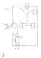
- Figure 1 is a simplified block diagram of an ultra miniature integrated cardiac pacemaker (100) in accordance with a first embodiment of this invention.
- the ultra miniature integrated cardiac pacemaker (100) in this embodiment is composed of a control unit (2) that outputs control signals, a heart stimulating means (3) that responds to the control signals and electrically stimulates the heart tissue, an electrocardiographic information detecting means (5) that detects the electrocardiographic information and outputs it to the control unit (2), a transmitting means (10) that modulates the control signals output from the control unit (2) and/or electrocardiographic information detected by the electrocardiographic information detecting means (5) and sends the information outside, a receiving means (9) that receives and demodulates the information sent from outside, and a power unit (4) that supplies the driving current.
- the heart stimulating means (3) responds to the control signal output from the control unit (2) and electrically stimulates the heart tissue.
- the heart stimulating means (3) as shown in the diagram is able to stimulate the heart tissue.
- the heart stimulating means (3) includes a stimulating unit (31) that responds to the control signals output from the control unit (2) and outputs heart stimulating pulses to stimulate the heart tissue, and two heart stimulating electrodes (32) that stimulate the heart tissue in response to the output pulses.
- the electrocardiographic information detecting means (5) detects the electrocardiographic information at the site where the ultra miniature integrated cardiac pacemaker is placed.
- the detected electrocardiographic information is output to the control unit (2).
- the electrocardiographic information detected by the electrocardiographic information detecting means (5) includes P wave information, QRS complex information, T wave information, or Q-T time, A-H time, H-V time (where A is atrial potential, H is His bundle potential, and V is ventricular potential).
- the electrocardiographic information detecting means (5) as shown in the diagram is composed of two electrocardiographic information recording electrodes (53) that detect the applied site electrocardiographic information at the placement site, an amplifying unit (51) that amplifies the electrocardiogram, and an A/D conversion (52) unit that converts the detected electrocardiographic information into digital signals.
- the electrocardiographic information detecting means (5) is designed such that the converted electrocardiographic information is output to the control unit (2).
- the transmitting means (10) is composed of a modulating unit (11) that inputs and modulates the control signals output from the control unit (2) and/or electrocardiographic information, and a transmitting unit (12) that sends the modulated control signals to the outside via carrier waves; by which the modulated control signals are sent to the outside (such as to other ultra miniature integrated cardiac pacemakers, not shown in the diagram).
- control signals and electrocardiographic information via carrier waves By transmitting control signals and electrocardiographic information via carrier waves to outside sites such as other cardiac pacemakers, it is possible, for example, to activate two or more cardiac pacemakers synchronously. Moreover, since carrier waves are used for transmission, there is no need for lead wires, and this method avoids imposing an extra burden on the user.
- the receiving means (9) is composed of a receiving unit (91) that receives information transmitted from the outside via carrier waves, and a demodulating unit (92) that demodulates the information received. It is designed such that the demodulated information is input into the control unit (2). Based on this information and/or electrocardiographic information, control signals are generated in the control unit (2) and output to the heart stimulating means (3).
- the information transmitted from the outside includes electrocardiographic information and control signals sent from other cardiac pacemakers.
- Possible modes of communication between pacemakers executed by the transmitting means (10) and receiving means (9) include, but are not limited to, spread spectrum communication using radio waves or ultrasound waves, and ultra wide band communication. There is no restriction on the mode of communication. Any method can be used as long as it provides reliable communication between pacemakers.
- the power unit (4) is designed to supply a power source necessary to drive the ultra miniature integrated cardiac pacemaker.
- a power unit (4) in general, it is possible to use a lithium battery or fuel cells.
- the power unit that supplies the electrical source is the largest component.
- a biological fuel cell is preferably used as the power unit (4).
- a biological fuel cell is used as the power unit
- biological fuels such as glucose and oxygen, which are necessary to drive the biological fuel cell, are available in constant supply inside the body.
- the volume of the power unit (4) depends only on the size of the electrodes, making it possible to miniaturize the volume of the power unit (4).
- metabolites and intermediate metabolic products of sugars e.g., glucose
- metabolites and intermediate metabolic products of sugars e.g., glucose
- e.g., glucose such as water, carbon dioxide and gluconolactone
- Biological fuel cells that use enzymes as catalysts can operate under mild conditions such as neutral pH and room temperature.
- a biological fuel cell used in this invention is the well-known conventional biological fuel cell that extracts electrons from oxidative reactions of biological fuels.
- This biological fuel cell uses sugars (such as glucose) and oxygen, both supplied by the body, as fuels, and utilizes enzymes as biological catalysts.
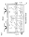
- Figure 2 is a schematic diagram illustrating the simplified structure of the biological fuel cell (40) as the power unit in the ultra miniature integrated cardiac pacemaker (100) of the first embodiment.
- the biological fuel cell (40) is composed of an anode (41) and a cathode (42).
- This biological fuel cell utilizes blood or body fluid as the electrolyte solution, and also utilizes sugars and oxygen in blood and body fluid as biological fuels. Therefore, the anode electrode (41a) and the cathode electrode (42a) are positioned so as to be in contact with blood or body fluid.
- the anode electrode (41a) and the cathode electrode (42a) are designed to be in contact with blood, and the heart stimulating electrode (32) and the electrocardiographic information recording electrode (53) are in contact with the myocardial tissue.
- the anode (41) is composed of an anode electrode (41a) and an immobile layer (41b) coating the surface of the anode electrode (41a).
- a gold electrode, etc. is preferably used as the anode electrode (41a).
- Oxidative enzymes of biological fuels and mediators necessary for the oxidation of biological fuels are immobilized on the surface of the anode electrode (41a).
- Carbohydrates are used as biological fuels.
- Examples of carbohydrates are monosaccharides such as glucose and fructose, disaccharides such as mannitol and sucrose, and pentoses such as xylose and arabinose.
- Glucose which can be supplied easily by the body, is preferably used as the fuel.
- Any oxidative enzymes that oxidize biological fuels can be used in the present invention.
- enzymes called oxidases and hydrogenases could be used.
- glucose is used as the biological fuel
- glucose oxidase and glucose dehydrogenase can be used.
- Glucose dehydrogenase is preferable.
- Any mediator that can transfer electrons released from the biological fuel to the anode electrode (41a) can be used in the present invention.
- Some examples include, but are not limited to, the so-called coenzymes such as flavin adenine dinucleotide phosphate, enzymes such as laccase, quinines such as pyrrolo-quinoline quinine, and osmium complex, as well as their combinations.
- the oxidative enzymes and mediators are immobilized on the surface of the anode electrode (41a) to form an immobile layer (41b).
- immobilization There is no restriction on the method of immobilization, and any method well known to immobilize enzymes onto an electrode surface can be used.
- a gold disc electrode can be used as the substrate, and aminoethane-thiol is adsorbed on the surface of the gold electrode to form a monomolecular film followed by modification of the amino groups.
- the method mixes the oxidative enzyme for biological fuel, the mediator and albumin in a beaker.
- glutaraldehyde is added to allow the enzymes and mediators to cross-link with glutaraldehyde and then the mixture is applied to the surface of the gold disc electrode.
- the immobile layer (41b) should preferably be designed such that the anode electrode (41a) does not come into contact with oxygen present in the body.
- the cathode (42) is composed of a cathode electrode (42a).
- cathode electrode (42a) is a platinum electrode.
- a catalyst to enhance a reaction involving reduction of oxygen is required on the cathode electrode (42a).
- the platinum itself can function as the catalyst.
- a coating (42b) on the surface of the cathode electrode which will prevent permeation of substances other than oxygen that react with the cathode electrode (42a), and at the same time allow permeation of oxygen and hydrogen ions.
- the biological fuel cell (40) does not have a container filled with electrolyte solution. Instead, the cathode electrode (41a) and the anode electrode (42a) are in contact with the blood or body fluid of the body. The blood and body fluid act as the electrolyte solution.
- biological fuel and oxygen are constantly supplied by the blood flow, and at the same time metabolic products are dissolved in blood and removed by the blood flow. The supply of biological fuel and oxygen as well as the removal of metabolic products are maintained constant through the mechanism of homeostasis.
- Biological fuel is dissolved in blood and body fluid and supplied to the anode (41) surface.
- the biological fuel supplied to the anode (41) surface is oxidized by the action of the biological fuel oxidative enzyme immobilized in the immobile layer (91b), producing carbon dioxide, hydrogen ion and intermediate metabolites, as well as electrons.
- Carbon dioxide, hydrogen ion and intermediate metabolites are dissolved in blood or body fluid to be excreted. Electrons are transferred to the anode electrode (41a) via mediators.
- the cathode (42) surface is supplied with oxygen and hydrogen ions dissolved in blood and body fluid, and these ions react in the presence of electrons transmitted from the anode electrode (41a) to the cathode electrode (42a), and form water. This reaction generates an electric current, which is used as the driving power source.
- control unit (2) Based on the program already saved in the memory (7) as well as on electrocardiographic information output from the electrocardiographic information detecting means (5) and information transmitted from the exterior, the control unit (2) generates control signals and outputs the signals into the heart stimulating means (3).
- control unit (2) is equipped with a stimulation timing determining means that decides the timing of stimulation to generate control signals, and a stimulation timing changing means that changes the timing of stimulation to generate control signals.
- this unit is programmed to generate control signals at stimulation timing at a predetermined frequency. It is also programmed to change the stimulation timing when certain conditions are fulfilled; for instance, in case intracardiac P wave information is detected within a given time interval.
- this invention can be equipped with a communication means (6).
- the communication means (6) communicates with an external programmer (8) installed external to the ultra miniature integrated cardiac pacemaker, and is used to change the pacing program saved in the memory (7).
- an external programmer (8) installed external to the ultra miniature integrated cardiac pacemaker, and is used to change the pacing program saved in the memory (7).
- the external programmer (8) and communication means (6) when a patient is implanted with multiple ultra miniature integrated cardiac pacemakers by setting different frequencies for the individual ultra miniature integrated cardiac pacemakers, for example, it is possible to change the pacing program for each ultra miniature integrated cardiac pacemaker. Also, by conducting spread spectrum communication or by giving each pacemaker an ID, it is possible to change the pacing program of each ultra miniature integrated cardiac pacemaker.
- the ultra miniature integrated cardiac pacemaker of the second embodiment (110) of the present invention will be explained.
- the difference between the ultra miniature integrated cardiac pacemaker in the second embodiment (110) and the aforementioned ultra miniature integrated cardiac pacemaker of the first embodiment (100) is that the former has no transmitting means (10) or receiving means (9).
- the ultra miniature integrated cardiac pacemaker of the second embodiment (110) can be used when there is no need to synchronize movements with other cardiac pacemakers.
- control unit (2) Based on the control program already saved in the memory (7) and on electrocardiographic information output from the electrocardiographic information detecting means (5), the control unit (2) generates control signals and outputs the signals to the heart stimulating means (3).
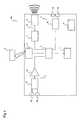
- FIG. 4 is a simplified block diagram of the ultra miniature integrated cardiac pacemaker in this embodiment (120).
- the difference between the ultra miniature integrated cardiac pacemaker in this embodiment (120) and the aforementioned ultra miniature integrated cardiac pacemaker of the first embodiment is that the former has no receiving means (9).
- the ultra miniature integrated cardiac pacemaker (120) By sending the control signals to the exterior (such as other cardiac pacemakers) via carrier waves, the ultra miniature integrated cardiac pacemaker (120) is able to synchronize and operate with, for instance, one or more other cardiac pacemakers.
- control unit (2) Based on the control program already saved in the memory (7) and electrocardiographic information output from the electrocardiographic information detecting means (5), the control unit (2) generates control signals and outputs the signals to the heart stimulating means (3).
- the ultra miniature integrated cardiac pacemaker of the fourth embodiment (130) of this invention will be explained.
- the difference between the ultra miniature integrated cardiac pacemaker in this embodiment (130) and the aforementioned ultra miniature integrated cardiac pacemaker in the first embodiment is that the former has no transmitting means (10) to send control signals and/or electrocardiographic information to the exterior.
- the ultra miniature integrated cardiac pacemaker (130) is able to synchronize and operate with other cardiac pacemakers.
- control unit (2) Based on the control program already saved in the memory (7), as well as electrocardiographic information output from the electrocardiographic information detecting means (5) and information transmitted from the exterior, the control unit (2) generates control signals and outputs the signals to the heart stimulating means (3).
- the electrocardiographic information recording electrodes (53) and the heart stimulating electrode (32) are shown as separate components. In reality, the electrocardiographic information recording electrode (53) and the heart stimulating electrode (32) may be shared.
- the receiving unit (91) and the transmitting unit (12) are shown as separate components; however, the receiving unit (91) and the transmitting unit (12) may also be shared.
- control unit (2) is able to generate control signals based on the biological data.
- the ultra miniature integrated cardiac pacemakers of the first four embodiments there is no particular restriction on the method of implanting the pacemaker in the heart and conventional methods for catheterization may be adopted. For instance, implantation may be done by attaching the ultra miniature integrated cardiac pacemaker to the tip of a catheter and inserting it into the predetermined position inside the heart, and then withdrawing only the catheter after fixing the pacemaker in the endocardium.
- the generator main body and the electrodes are integrated, thus obviating the need for lead wires. Therefore, the ultra miniature integrated cardiac pacemakers of the invention can be made of a size of only 2 to 3 mm in diameter. There is no need to make a wide incision in the chest wall to implant the generator main body.
- the present invention provides an ultra miniature integrated cardiac pacemaker which allows pacing of the heart without the need for the conventional lead wires that connect the electrodes with the pacemaker main body, and allow implantation in the heart by catheter manipulation only without incision of the chest wall to reduce burden on the patient.
Landscapes
- Health & Medical Sciences (AREA)
- Life Sciences & Earth Sciences (AREA)
- Engineering & Computer Science (AREA)
- Cardiology (AREA)
- Animal Behavior & Ethology (AREA)
- Radiology & Medical Imaging (AREA)
- Nuclear Medicine, Radiotherapy & Molecular Imaging (AREA)
- General Health & Medical Sciences (AREA)
- Public Health (AREA)
- Veterinary Medicine (AREA)
- Biomedical Technology (AREA)
- Heart & Thoracic Surgery (AREA)
- Chemical & Material Sciences (AREA)
- Biophysics (AREA)
- Physiology (AREA)
- Microbiology (AREA)
- Chemical Kinetics & Catalysis (AREA)
- Electrochemistry (AREA)
- General Chemical & Material Sciences (AREA)
- Manufacturing & Machinery (AREA)
- Sustainable Development (AREA)
- Biochemistry (AREA)
- Sustainable Energy (AREA)
- Molecular Biology (AREA)
- Electrotherapy Devices (AREA)
- Measurement And Recording Of Electrical Phenomena And Electrical Characteristics Of The Living Body (AREA)
- Compositions Of Oxide Ceramics (AREA)
- Inert Electrodes (AREA)
Abstract
Description
- The present invention concerns an ultra miniature integrated cardiac pacemaker and distributed cardiac pacing system. The invention provides an ultra miniature integrated cardiac pacemaker and distributed cardiac pacing system that allows pacing of the heart without the need for conventional lead wires that connect the electrodes and the main body of the pacemaker, and allows implantation by catheter manipulation without incising the chest wall, which avoids imposing an extra burden on the user.
- In this invention, "ultra miniature" refers to the minute size of the pacemaker to the extent that it can be attached to the tip of a catheter.
- A cardiac pacemaker is a device that controls the rhythm of the heart by delivering electrical impulses to the heart, and is indicated for use in patients with symptoms of bradyarrhythmia.
- A conventional cardiac pacemaker includes the main body of the cardiac pacemaker (generator), lead wires, and electrodes that transmit a stimulating pulse to the myocardium. The main body of the cardiac pacemaker and the electrodes are connected by lead wires. However, conventional pacemakers have the following problems.
- Since the main body of the cardiac pacemaker and the electrodes are connected by lead wires, cases of breaking of the lead wires have occurred. Breakage of the lead wires results in defective pacing. In addition, there have been also cases of venous obstruction by the lead wires.
- Moreover, during the early stages after implantation of the cardiac pacemaker, a shift in position of the electrodes may cause defective pacing. When a shift in position of the electrodes occurs, a second operation has to be performed, which adds extra strain for the patient.
- Furthermore, if there is a defective hermetic sealing structure at the junction between the cardiac pacemaker main body and the lead wires, this may lead to defective pacemaker movement. Problems with electrical safety have also occurred.
- In the Unexamined Japanese Patent Publication Heisei No.
5-245215 - However, even for this type of cardiac pacemaker, surgical implantation of the pacemaker cannot be avoided, and there have been cases in which skin necrosis occurred at the cardiac pacemaker implantation site.
- Also, in the above-mentioned cardiac pacemaker, although wireless communication is conducted between the pacemaker main body and the electrodes, there is no communication between the electrodes. Synchrony between the multiple electrodes being used is controller by the pacemaker main body.
- The present invention was developed in order to solve the above problems, and to provide an ultra miniature integrated cardiac pacemaker and distributed cardiac pacing system with the following features: the generator function of electric stimulus by the pacemaker main body is integrated with the electrodes, thus allowing pacing of the heart without the need for conventional lead wires connecting the electrodes and pacemaker main body. By integrating the control unit of the pacemaker main body and the electrodes, there is no need to implant the pacemaker main body, which avoids imposing an extra burden on the user.
-
EP 0443496 discloses an implantable heart pacemaker including means for monitoring electrical signals generated by the heart and for producing a corresponding electrocardiogram signal in order to stimulate the heart by stimulation means. -
GB 1422171 - The invention is set out in claim 1.
- The ultra miniature integrated cardiac pacemaker of the present invention requires no chest incision, and is implanted in the heart by attaching it to the tip of a catheter and extracting the catheter after implanting.
- In one embodiment, the pacemaker includes a control unit that outputs control signals, a heart stimulating means that responds to the control signal and electrically stimulates the heart tissue, an electrocardiographic information detecting means that detects the electrocardiographic information and outputs it to the control unit, and a power unit that supplies the driving power.
- The control unit outputs the control signals based on electrocardiographic information.
- The power unit is preferably a biological fuel cell that extracts electrons from oxidative reactions of biological fuels. The biological fuel cell is composed of an anode electrode and a cathode electrode. The anode electrode is coated with immobilized oxidative enzymes for biological fuels and mediators. The biological fuel cell uses blood and/or body fluid as an electrolyte solution and utilizes biological fuels and oxygen in blood and/or body fluid.
- In another embodiment of the present invention, an ultra miniature integrated cardiac pacemaker includes a control unit that outputs control signals, a heart stimulating means that responds to the control signal and electrically stimulates the heart tissue, an electrocardiographic information detecting means that detects the electrocardiographic information and outputs it to the control unit, a transmitting means that modulates the electrocardiographic information and control signals to be sent outside, and a power unit that supplies the driving power.
- The control unit outputs the control signals based on electrocardiographic information.
- The power unit is preferably a biological fuel cell that extracts electrons from oxidative reactions of biological fuels. The biological fuel cell is composed of an anode electrode and a cathode electrode. The anode electrode is coated with immobilized oxidative enzymes for biological fuels and mediators. The biological fuel cell uses blood and/or body fluid as an electrolyte solution and utilizes biological fuels and oxygen in blood and/or body fluid.
- In a third embodiment, an ultra miniature integrated cardiac pacemaker includes a control unit that outputs control signals, a heart stimulating means that responds to the control signal and electrically stimulates the heart tissue, an electrocardiographic information detecting means that detects the electrocardiographic information and outputs it to the control unit, a receiving means that receives and demodulates the information sent from outside, and a power unit that supplies the driving power. It is designed such that the information sent from outside is input into the control unit.
- The control unit outputs control signals based on information sent from outside and/or electrocardiographic information.
- The power unit is preferably a biological fuel cell that extracts electrons from oxidative reactions of biological fuels. The biological fuel cell is composed of an anode electrode and a cathode electrode. The anode electrode is coated with immobilized oxidative enzymes for biological fuels and mediators. The biological fuel cell uses blood and/or body fluid as an electrolyte solution and utilizes biological fuels and oxygen in blood and/or body fluid.
- In yet another embodiment, an ultra miniature integrated cardiac pacemaker includes a control unit that outputs control signals, a heart stimulating means that responds to the control signal and electrically stimulates the heart tissue, an electrocardiographic information detecting means that detects the electrocardiographic information and outputs it to the control unit, a transmitting means that modulates the electrocardiographic information and control signals to be sent outside, a receiving means that receives and demodulates the information sent from outside, and a power unit that supplies the driving current. It is designed such that the information sent from outside is input into the control unit.
- The control unit outputs control signals based on information sent from outside and/or electrocardiographic information.
- The power unit is preferably a biological fuel cell that extracts electrons from oxidative reactions of biological fuels. The biological fuel cell is composed of an anode electrode and a cathode electrode. The anode electrode is coated with immobilized oxidative enzymes for biological fuels and mediators. The biological fuel cell uses blood and/or body fluid as electrolyte solution and utilizes biological fuels and oxygen in blood and/or body fluid.
- Another embodiment discloses an ultra miniature integrated cardiac pacemaker placed in the atrial myocardium.
- The ultra miniature integrated cardiac pacemaker is equipped with a control unit that outputs control signals, a power unit that supplies the driving power, a heart stimulating means that responds to the control signals and electrically stimulates the atrial myocardium, and an electrocardiographic information detecting means that detects the electrocardiographic information including at least intracardiac P wave information.
- The power unit is preferably a biological fuel cell that extracts electrons from oxidative reactions of biological fuels. The biological fuel cell is composed of an anode electrode and a cathode electrode. The anode electrode is coated with immobilized oxidative enzymes for biological fuels and mediators. The biological fuel cell uses blood and/or body fluid as an electrolyte solution and utilizes biological fuels and oxygen in blood and/or body fluid.
- The control unit is equipped with a stimulation timing determining means that decides the timing of stimulation to generate control signals, and a stimulation timing changing means that changes the timing of stimulation to generate control signals. It is characterized by the ability to change the timing of stimulation to generate the control signal, in case intracardiac P wave information is detected within a preset time interval.
-
- Figure 1
- is a simplified block diagram of an ultra miniature integrated cardiac pacemaker in accordance with the first embodiment.
- Figure 2
- is a simplified block diagram of an ultra miniature integrated cardiac pacemaker in accordance with the first embodiment.
- Figure 3
- is a simplified block diagram of an ultra miniature integrated cardiac pacemaker in accordance with the second embodiment.
- Figure 4
- is a simplified block diagram of an ultra miniature integrated cardiac pacemaker in accordance with the third embodiment.
- Figure 5
- is a simplified block diagram of an ultra miniature integrated cardiac pacemaker in accordance with the fourth embodiment.
- Figure 6
- is a schematic diagram illustrating a first application of the ultra miniature integrated cardiac pacemaker in accordance with the present invention (the first distributed cardiac pacing system).
- Figure 7
- is a schematic diagram illustrating a second application of the ultra miniature integrated cardiac pacemaker in accordance with the present invention (the second distributed cardiac pacing system).
- Figure 8
- is a block diagram illustrating an outline of the electrocardiographic information detection device.
- Figure 9
- is a schematic diagram illustrating a third application of the ultra miniature integrated cardiac pacemaker in accordance with the present invention (the third distributed cardiac pacing system).
- Figure 10
- is a schematic diagram illustrating a fourth application of the ultra miniature integrated cardiac pacemaker in accordance with the present invention (the fourth distributed cardiac pacing system).
- The present invention is described in detail below while referring to the figures.
Figure 1 is a simplified block diagram of an ultra miniature integrated cardiac pacemaker (100) in accordance with a first embodiment of this invention. - The ultra miniature integrated cardiac pacemaker (100) in this embodiment is composed of a control unit (2) that outputs control signals, a heart stimulating means (3) that responds to the control signals and electrically stimulates the heart tissue, an electrocardiographic information detecting means (5) that detects the electrocardiographic information and outputs it to the control unit (2), a transmitting means (10) that modulates the control signals output from the control unit (2) and/or electrocardiographic information detected by the electrocardiographic information detecting means (5) and sends the information outside, a receiving means (9) that receives and demodulates the information sent from outside, and a power unit (4) that supplies the driving current.
- The heart stimulating means (3) responds to the control signal output from the control unit (2) and electrically stimulates the heart tissue. The heart stimulating means (3) as shown in the diagram is able to stimulate the heart tissue. The heart stimulating means (3) includes a stimulating unit (31) that responds to the control signals output from the control unit (2) and outputs heart stimulating pulses to stimulate the heart tissue, and two heart stimulating electrodes (32) that stimulate the heart tissue in response to the output pulses.
- The electrocardiographic information detecting means (5) detects the electrocardiographic information at the site where the ultra miniature integrated cardiac pacemaker is placed. The detected electrocardiographic information is output to the control unit (2). The electrocardiographic information detected by the electrocardiographic information detecting means (5) includes P wave information, QRS complex information, T wave information, or Q-T time, A-H time, H-V time (where A is atrial potential, H is His bundle potential, and V is ventricular potential).
- The electrocardiographic information detecting means (5) as shown in the diagram is composed of two electrocardiographic information recording electrodes (53) that detect the applied site electrocardiographic information at the placement site, an amplifying unit (51) that amplifies the electrocardiogram, and an A/D conversion (52) unit that converts the detected electrocardiographic information into digital signals. The electrocardiographic information detecting means (5) is designed such that the converted electrocardiographic information is output to the control unit (2).
- The transmitting means (10) is composed of a modulating unit (11) that inputs and modulates the control signals output from the control unit (2) and/or electrocardiographic information, and a transmitting unit (12) that sends the modulated control signals to the outside via carrier waves; by which the modulated control signals are sent to the outside (such as to other ultra miniature integrated cardiac pacemakers, not shown in the diagram).
- By transmitting control signals and electrocardiographic information via carrier waves to outside sites such as other cardiac pacemakers, it is possible, for example, to activate two or more cardiac pacemakers synchronously. Moreover, since carrier waves are used for transmission, there is no need for lead wires, and this method avoids imposing an extra burden on the user.
- The receiving means (9) is composed of a receiving unit (91) that receives information transmitted from the outside via carrier waves, and a demodulating unit (92) that demodulates the information received. It is designed such that the demodulated information is input into the control unit (2). Based on this information and/or electrocardiographic information, control signals are generated in the control unit (2) and output to the heart stimulating means (3).
- The information transmitted from the outside includes electrocardiographic information and control signals sent from other cardiac pacemakers.
- By equipping the receiving means (9) that receives information from, for instance, other cardiac pacemakers, it is possible to activate the cardiac pacemaker synchronously with other cardiac pacemakers. Moreover, since there is no need for lead wires, this method avoids imposing extra burden on the user.
- Possible modes of communication between pacemakers executed by the transmitting means (10) and receiving means (9) include, but are not limited to, spread spectrum communication using radio waves or ultrasound waves, and ultra wide band communication. There is no restriction on the mode of communication. Any method can be used as long as it provides reliable communication between pacemakers.
- The power unit (4) is designed to supply a power source necessary to drive the ultra miniature integrated cardiac pacemaker. As a power unit (4), in general, it is possible to use a lithium battery or fuel cells. However, in the conventional cardiac pacemakers, the power unit that supplies the electrical source is the largest component. To ultra-miniaturize the cardiac pacemaker, it is necessary to miniaturize the power unit. For the ultra miniature integrated cardiac pacemaker (100) according to the present invention, a biological fuel cell is preferably used as the power unit (4).
- If a biological fuel cell is used as the power unit, biological fuels such as glucose and oxygen, which are necessary to drive the biological fuel cell, are available in constant supply inside the body. The volume of the power unit (4) depends only on the size of the electrodes, making it possible to miniaturize the volume of the power unit (4). Moreover, metabolites and intermediate metabolic products of sugars (e.g., glucose), such as water, carbon dioxide and gluconolactone, are safe for the human body and they are rapidly removed from the vicinity of the electrodes by blood flow. Biological fuel cells that use enzymes as catalysts can operate under mild conditions such as neutral pH and room temperature.
- One example of a biological fuel cell used in this invention is the well-known conventional biological fuel cell that extracts electrons from oxidative reactions of biological fuels. This biological fuel cell uses sugars (such as glucose) and oxygen, both supplied by the body, as fuels, and utilizes enzymes as biological catalysts.
- An example of the composition of the preferable biological fuel cell (40) for this invention will be explained by referring to the diagram.
Figure 2 is a schematic diagram illustrating the simplified structure of the biological fuel cell (40) as the power unit in the ultra miniature integrated cardiac pacemaker (100) of the first embodiment. - The biological fuel cell (40) is composed of an anode (41) and a cathode (42). This biological fuel cell utilizes blood or body fluid as the electrolyte solution, and also utilizes sugars and oxygen in blood and body fluid as biological fuels. Therefore, the anode electrode (41a) and the cathode electrode (42a) are positioned so as to be in contact with blood or body fluid. In
Figure 2 , the anode electrode (41a) and the cathode electrode (42a) are designed to be in contact with blood, and the heart stimulating electrode (32) and the electrocardiographic information recording electrode (53) are in contact with the myocardial tissue. - The anode (41) is composed of an anode electrode (41a) and an immobile layer (41b) coating the surface of the anode electrode (41a). A gold electrode, etc. is preferably used as the anode electrode (41a).
- Oxidative enzymes of biological fuels and mediators necessary for the oxidation of biological fuels are immobilized on the surface of the anode electrode (41a).
- Carbohydrates are used as biological fuels. Examples of carbohydrates are monosaccharides such as glucose and fructose, disaccharides such as mannitol and sucrose, and pentoses such as xylose and arabinose. Glucose, which can be supplied easily by the body, is preferably used as the fuel.
- Any oxidative enzymes that oxidize biological fuels can be used in the present invention. For example, enzymes called oxidases and hydrogenases could be used. If glucose is used as the biological fuel, glucose oxidase and glucose dehydrogenase can be used. Glucose dehydrogenase is preferable.
- Any mediator that can transfer electrons released from the biological fuel to the anode electrode (41a) can be used in the present invention. Some examples include, but are not limited to, the so-called coenzymes such as flavin adenine dinucleotide phosphate, enzymes such as laccase, quinines such as pyrrolo-quinoline quinine, and osmium complex, as well as their combinations.
- The oxidative enzymes and mediators are immobilized on the surface of the anode electrode (41a) to form an immobile layer (41b). There is no restriction on the method of immobilization, and any method well known to immobilize enzymes onto an electrode surface can be used. For example, a gold disc electrode can be used as the substrate, and aminoethane-thiol is adsorbed on the surface of the gold electrode to form a monomolecular film followed by modification of the amino groups. After that, the method mixes the oxidative enzyme for biological fuel, the mediator and albumin in a beaker. Then glutaraldehyde is added to allow the enzymes and mediators to cross-link with glutaraldehyde and then the mixture is applied to the surface of the gold disc electrode.
- To ensure that the reaction takes place efficiently at the anode, the immobile layer (41b) should preferably be designed such that the anode electrode (41a) does not come into contact with oxygen present in the body.
- The cathode (42) is composed of a cathode electrode (42a).
- An example of the cathode electrode (42a) is a platinum electrode. A catalyst to enhance a reaction involving reduction of oxygen is required on the cathode electrode (42a). The platinum itself can function as the catalyst.
- To ensure that the reaction takes place efficiently at the cathode, it is desirable to form a coating (42b) on the surface of the cathode electrode, which will prevent permeation of substances other than oxygen that react with the cathode electrode (42a), and at the same time allow permeation of oxygen and hydrogen ions.
- The biological fuel cell (40) does not have a container filled with electrolyte solution. Instead, the cathode electrode (41a) and the anode electrode (42a) are in contact with the blood or body fluid of the body. The blood and body fluid act as the electrolyte solution. In the electrolyte solution, biological fuel and oxygen are constantly supplied by the blood flow, and at the same time metabolic products are dissolved in blood and removed by the blood flow. The supply of biological fuel and oxygen as well as the removal of metabolic products are maintained constant through the mechanism of homeostasis.
- Next, the action of the biological fuel cell (40) will be discussed.
- Biological fuel is dissolved in blood and body fluid and supplied to the anode (41) surface. The biological fuel supplied to the anode (41) surface is oxidized by the action of the biological fuel oxidative enzyme immobilized in the immobile layer (91b), producing carbon dioxide, hydrogen ion and intermediate metabolites, as well as electrons. Carbon dioxide, hydrogen ion and intermediate metabolites are dissolved in blood or body fluid to be excreted. Electrons are transferred to the anode electrode (41a) via mediators.
- The cathode (42) surface is supplied with oxygen and hydrogen ions dissolved in blood and body fluid, and these ions react in the presence of electrons transmitted from the anode electrode (41a) to the cathode electrode (42a), and form water. This reaction generates an electric current, which is used as the driving power source.
- Based on the program already saved in the memory (7) as well as on electrocardiographic information output from the electrocardiographic information detecting means (5) and information transmitted from the exterior, the control unit (2) generates control signals and outputs the signals into the heart stimulating means (3).
- For instance, the control unit (2) is equipped with a stimulation timing determining means that decides the timing of stimulation to generate control signals, and a stimulation timing changing means that changes the timing of stimulation to generate control signals. Usually this unit is programmed to generate control signals at stimulation timing at a predetermined frequency. It is also programmed to change the stimulation timing when certain conditions are fulfilled; for instance, in case intracardiac P wave information is detected within a given time interval.
- Furthermore, this invention can be equipped with a communication means (6). The communication means (6) communicates with an external programmer (8) installed external to the ultra miniature integrated cardiac pacemaker, and is used to change the pacing program saved in the memory (7). By this means, even after implantation of the ultra miniature integrated cardiac pacemaker in the patient, it is possible to use the external programmer (8) to change the pacing program saved in the memory (7) as appropriate for the particular patient.
- For communication between the external programmer (8) and communication means (6) when a patient is implanted with multiple ultra miniature integrated cardiac pacemakers, by setting different frequencies for the individual ultra miniature integrated cardiac pacemakers, for example, it is possible to change the pacing program for each ultra miniature integrated cardiac pacemaker. Also, by conducting spread spectrum communication or by giving each pacemaker an ID, it is possible to change the pacing program of each ultra miniature integrated cardiac pacemaker.
- Next, the ultra miniature integrated cardiac pacemaker of the second embodiment (110) of the present invention will be explained. The difference between the ultra miniature integrated cardiac pacemaker in the second embodiment (110) and the aforementioned ultra miniature integrated cardiac pacemaker of the first embodiment (100) is that the former has no transmitting means (10) or receiving means (9).
- The ultra miniature integrated cardiac pacemaker of the second embodiment (110) can be used when there is no need to synchronize movements with other cardiac pacemakers.
- Based on the control program already saved in the memory (7) and on electrocardiographic information output from the electrocardiographic information detecting means (5), the control unit (2) generates control signals and outputs the signals to the heart stimulating means (3).
- The other components are the same as those in the aforementioned ultra miniature integrated cardiac pacemaker of the first embodiment (100), therefore explanations are omitted. In
Figure 3 , the same numbers are assigned to components identical to those in the first embodiment (100) as shown inFigure 1 . - Next, the ultra miniature integrated cardiac pacemaker of the third embodiment (120) of this invention will be explained.
Figure 4 is a simplified block diagram of the ultra miniature integrated cardiac pacemaker in this embodiment (120). The difference between the ultra miniature integrated cardiac pacemaker in this embodiment (120) and the aforementioned ultra miniature integrated cardiac pacemaker of the first embodiment is that the former has no receiving means (9). - By sending the control signals to the exterior (such as other cardiac pacemakers) via carrier waves, the ultra miniature integrated cardiac pacemaker (120) is able to synchronize and operate with, for instance, one or more other cardiac pacemakers.
- Based on the control program already saved in the memory (7) and electrocardiographic information output from the electrocardiographic information detecting means (5), the control unit (2) generates control signals and outputs the signals to the heart stimulating means (3).
- The other components are the same as those in the aforementioned ultra miniature integrated cardiac pacemaker of the first embodiment, therefore explanations are omitted. In
Figure 4 , the same numbers are assigned to components identical to those in the ultra miniature integrated cardiac pacemaker in accordance with the first and second embodiments shown inFigures 1 and3 . - Next, the ultra miniature integrated cardiac pacemaker of the fourth embodiment (130) of this invention will be explained. The difference between the ultra miniature integrated cardiac pacemaker in this embodiment (130) and the aforementioned ultra miniature integrated cardiac pacemaker in the first embodiment is that the former has no transmitting means (10) to send control signals and/or electrocardiographic information to the exterior.
- Through the receiving means (9) that receives information from the exterior, for example, from other cardiac pacemakers, the ultra miniature integrated cardiac pacemaker (130) is able to synchronize and operate with other cardiac pacemakers.
- Based on the control program already saved in the memory (7), as well as electrocardiographic information output from the electrocardiographic information detecting means (5) and information transmitted from the exterior, the control unit (2) generates control signals and outputs the signals to the heart stimulating means (3).
- The other components are the same as those in the aforementioned ultra miniature integrated cardiac pacemaker of the first embodiment, therefore explanations are omitted. In
Figure 5 , the same numbers are assigned to components identical to those in the ultra miniature integrated cardiac pacemakers in accordance with the first three embodiments shown inFigures 1 ,3 and4 . - In the ultra miniature integrated cardiac pacemakers of the first four embodiments, the electrocardiographic information recording electrodes (53) and the heart stimulating electrode (32) are shown as separate components. In reality, the electrocardiographic information recording electrode (53) and the heart stimulating electrode (32) may be shared.
- Moreover, the receiving unit (91) and the transmitting unit (12) are shown as separate components; however, the receiving unit (91) and the transmitting unit (12) may also be shared.
- Furthermore, by installing in the patient a sensor that measures body temperature and blood pressure and outputting the biological information obtained from these sensors to the control unit (2) of the ultra miniature integrated cardiac pacemakers of the first four embodiments, the control unit (2) is able to generate control signals based on the biological data.
- In addition, for the ultra miniature integrated cardiac pacemakers of the first four embodiments, there is no particular restriction on the method of implanting the pacemaker in the heart and conventional methods for catheterization may be adopted. For instance, implantation may be done by attaching the ultra miniature integrated cardiac pacemaker to the tip of a catheter and inserting it into the predetermined position inside the heart, and then withdrawing only the catheter after fixing the pacemaker in the endocardium. In the ultra miniature integrated cardiac pacemakers of the invention, the generator main body and the electrodes are integrated, thus obviating the need for lead wires. Therefore, the ultra miniature integrated cardiac pacemakers of the invention can be made of a size of only 2 to 3 mm in diameter. There is no need to make a wide incision in the chest wall to implant the generator main body.
- The present invention provides an ultra miniature integrated cardiac pacemaker which allows pacing of the heart without the need for the conventional lead wires that connect the electrodes with the pacemaker main body, and allow implantation in the heart by catheter manipulation only without incision of the chest wall to reduce burden on the patient.
- Accordingly, it is to be understood that the embodiments of the invention herein described are merely illustrative of the application of the principles of the invention. Reference herein to details of the illustrated embodiments is not intended to limit the scope of the claims, which themselves recite those features regarded as essential to the invention.
Claims (5)
- An ultra miniature integrated cardiac pacemaker (100) requiring no chest incision, which can be implanted in a heart by attaching the pacemaker to a tip of a catheter and extracting the catheter after implanting, comprising:a) a control unit (2) that outputs at least one control signal,b) a heart stimulating means (3) that responds to the control signal and electrically stimulates heart tissue,c) an electrocardiographic information detecting means (5) that detects a plurality of electrocardiographic information and outputs the electrocardiographic information to the control unit (2), andd) a power unit (4) that supplies power to the pacemaker (100),wherein the control unit (2) outputs the control signal based on the electrocardiographic information, characterized in that the power unit (4) is a biological fuel cell (40) to extract electrons from oxidative reactions of biological fuels comprising a cathode electrode (42) and an anode electrode (41) coated with immobilized oxidative enzymes for biological fuels and mediators, and the biological fuel cell (40) uses blood and/or body fluid as an electrolyte solution and utilizes biological fuels and oxygen in blood and/or body fluid.
- An ultra miniature integrated cardiac pacemaker (100) according to Claim 1 comprising a transmitting means (10) that modulates the electrocardiographic information and the control signal to be sent outside.
- An ultra miniature integrated cardiac pacemaker (100) according to Claim 1 comprising a receiving means (9) that demodulates information transmitted from outside,
characterized in that information sent from the outside is input into the control unit(2), which outputs the control signal based on information sent from outside and/or the own electrocardiographic information. - An ultra miniature integrated cardiac pacemaker (100) according to Claim 1 comprising, (a) a transmitting means (10) that modulates the electrocardiographic information and control signal to be sent outside, (b) a receiving means (9) that demodulates information transmitted from outside,
characterized in that the information sent from outside is input into the control unit (2), which outputs the control signal based on the information sent from outside and/or electrocardiographic information. - An ultra miniature integrated cardiac pacemaker (100) according to Claim 1 placed in the atrial myocardium,
characterized in that the heart stimulating means (3) stimulates the atrial myocardium by responding to the control signal when intracardiac P wave information is not detected within a given time, and suppresses generation of the control signal when intracardiac P wave information is detected within a given time.
Priority Applications (1)
| Application Number | Priority Date | Filing Date | Title |
|---|---|---|---|
| EP08022222A EP2047887B1 (en) | 2002-08-05 | 2003-08-04 | Distributed cardiac pacing system |
Applications Claiming Priority (3)
| Application Number | Priority Date | Filing Date | Title |
|---|---|---|---|
| PCT/JP2002/007972 WO2004012810A1 (en) | 2002-08-05 | 2002-08-05 | Subminiature integrated heart pace maker and dispersed heart pacing system |
| JP2002007972 | 2002-08-05 | ||
| PCT/JP2003/009886 WO2004012811A1 (en) | 2002-08-05 | 2003-08-04 | Micro integrated cardiac pacemaker and distributed cardiac pacing system |
Related Child Applications (1)
| Application Number | Title | Priority Date | Filing Date |
|---|---|---|---|
| EP08022222A Division EP2047887B1 (en) | 2002-08-05 | 2003-08-04 | Distributed cardiac pacing system |
Publications (3)
| Publication Number | Publication Date |
|---|---|
| EP1541191A1 EP1541191A1 (en) | 2005-06-15 |
| EP1541191A4 EP1541191A4 (en) | 2007-09-05 |
| EP1541191B1 true EP1541191B1 (en) | 2009-11-11 |
Family
ID=31217261
Family Applications (2)
| Application Number | Title | Priority Date | Filing Date |
|---|---|---|---|
| EP03766728A Expired - Lifetime EP1541191B1 (en) | 2002-08-05 | 2003-08-04 | Micro integrated cardiac pacemaker |
| EP08022222A Expired - Lifetime EP2047887B1 (en) | 2002-08-05 | 2003-08-04 | Distributed cardiac pacing system |
Family Applications After (1)
| Application Number | Title | Priority Date | Filing Date |
|---|---|---|---|
| EP08022222A Expired - Lifetime EP2047887B1 (en) | 2002-08-05 | 2003-08-04 | Distributed cardiac pacing system |
Country Status (11)
| Country | Link |
|---|---|
| US (2) | US8027729B2 (en) |
| EP (2) | EP1541191B1 (en) |
| JP (1) | JP4189442B2 (en) |
| KR (1) | KR100657361B1 (en) |
| CN (1) | CN100438940C (en) |
| AT (1) | ATE447999T1 (en) |
| AU (2) | AU2002323811A1 (en) |
| DE (1) | DE60330024D1 (en) |
| IL (1) | IL166572A (en) |
| RU (1) | RU2297854C2 (en) |
| WO (2) | WO2004012810A1 (en) |
Cited By (2)
| Publication number | Priority date | Publication date | Assignee | Title |
|---|---|---|---|---|
| US9492671B2 (en) | 2014-05-06 | 2016-11-15 | Medtronic, Inc. | Acoustically triggered therapy delivery |
| US9511233B2 (en) | 2013-11-21 | 2016-12-06 | Medtronic, Inc. | Systems and methods for leadless cardiac resynchronization therapy |
Families Citing this family (157)
| Publication number | Priority date | Publication date | Assignee | Title |
|---|---|---|---|---|
| US7260369B2 (en) * | 2005-08-03 | 2007-08-21 | Kamilo Feher | Location finder, tracker, communication and remote control system |
| CA2568064A1 (en) * | 2004-06-01 | 2005-12-15 | Remon Medical Technologies Ltd | System for evaluating heart performance |
| CA2583404A1 (en) | 2004-10-20 | 2006-04-27 | Boston Scientific Limited | Leadless cardiac stimulation systems |
| US7532933B2 (en) * | 2004-10-20 | 2009-05-12 | Boston Scientific Scimed, Inc. | Leadless cardiac stimulation systems |
| US8818504B2 (en) * | 2004-12-16 | 2014-08-26 | Cardiac Pacemakers Inc | Leadless cardiac stimulation device employing distributed logic |
| US7962208B2 (en) | 2005-04-25 | 2011-06-14 | Cardiac Pacemakers, Inc. | Method and apparatus for pacing during revascularization |
| US8391990B2 (en) | 2005-05-18 | 2013-03-05 | Cardiac Pacemakers, Inc. | Modular antitachyarrhythmia therapy system |
| EP2471450A1 (en) | 2005-10-14 | 2012-07-04 | Nanostim, Inc. | Leadless cardiac pacemaker and system |
| US9168383B2 (en) | 2005-10-14 | 2015-10-27 | Pacesetter, Inc. | Leadless cardiac pacemaker with conducted communication |
| EP1957147B1 (en) | 2005-12-09 | 2010-12-29 | Boston Scientific Scimed, Inc. | Cardiac stimulation system |
| WO2007068284A1 (en) * | 2005-12-12 | 2007-06-21 | Synergio Ag | Intra cardiac device, system and methods |
| US7885710B2 (en) | 2005-12-23 | 2011-02-08 | Cardiac Pacemakers, Inc. | Method and apparatus for tissue protection against ischemia using remote conditioning |
| US7519424B2 (en) * | 2006-01-30 | 2009-04-14 | Medtronic, Inc. | Intravascular medical device |
| US7616992B2 (en) * | 2006-01-30 | 2009-11-10 | Medtronic, Inc. | Intravascular medical device |
| US7627376B2 (en) * | 2006-01-30 | 2009-12-01 | Medtronic, Inc. | Intravascular medical device |
| US20070233187A1 (en) * | 2006-04-04 | 2007-10-04 | Medtronic Vascular, Inc. | Self-closing medical staple |
| ATE551747T1 (en) * | 2006-05-05 | 2012-04-15 | Spencer J G Epps | IMPLANTABLE GALAVANIC ELEMENT |
| US8290600B2 (en) | 2006-07-21 | 2012-10-16 | Boston Scientific Scimed, Inc. | Electrical stimulation of body tissue using interconnected electrode assemblies |
| US7840281B2 (en) | 2006-07-21 | 2010-11-23 | Boston Scientific Scimed, Inc. | Delivery of cardiac stimulation devices |
| US20080071315A1 (en) * | 2006-08-31 | 2008-03-20 | Tamara Colette Baynham | Integrated catheter and pulse generator systems and methods |
| US8644934B2 (en) | 2006-09-13 | 2014-02-04 | Boston Scientific Scimed Inc. | Cardiac stimulation using leadless electrode assemblies |
| WO2008107838A1 (en) * | 2007-03-07 | 2008-09-12 | Koninklijke Philips Electronics N.V. | Apparatus and method for applying energy within an object |
| WO2009099550A1 (en) | 2008-02-07 | 2009-08-13 | Cardiac Pacemakers, Inc. | Wireless tissue electrostimulation |
| US8639357B2 (en) | 2008-06-19 | 2014-01-28 | Cardiac Pacemakers, Inc. | Pacing catheter with stent electrode |
| US8244352B2 (en) | 2008-06-19 | 2012-08-14 | Cardiac Pacemakers, Inc. | Pacing catheter releasing conductive liquid |
| US9037235B2 (en) | 2008-06-19 | 2015-05-19 | Cardiac Pacemakers, Inc. | Pacing catheter with expandable distal end |
| US9409012B2 (en) | 2008-06-19 | 2016-08-09 | Cardiac Pacemakers, Inc. | Pacemaker integrated with vascular intervention catheter |
| US8457738B2 (en) | 2008-06-19 | 2013-06-04 | Cardiac Pacemakers, Inc. | Pacing catheter for access to multiple vessels |
| US8170661B2 (en) * | 2008-07-01 | 2012-05-01 | Cardiac Pacemakers, Inc. | Pacing system controller integrated into indeflator |
| US9248301B2 (en) * | 2008-07-29 | 2016-02-02 | Koninklijke Philips N.V. | System and method for communicating information between implantable devices |
| GB0817041D0 (en) * | 2008-09-17 | 2008-10-22 | Smith & Nephew | Power generation |
| GB2464148A (en) * | 2008-09-23 | 2010-04-14 | Richard Terrance Pinder | A road and railway based piezo electrical generator |
| WO2010088687A1 (en) | 2009-02-02 | 2010-08-05 | Nanostim, Inc. | Leadless cardiac pacemaker with secondary fixation capability |
| CN102470240B (en) * | 2009-07-24 | 2015-09-09 | 沙皮恩斯脑部刺激控制有限公司 | For the armarium of electricity irritation |
| JPWO2011046006A1 (en) | 2009-10-16 | 2013-03-04 | オリンパス株式会社 | Fuel cell, battery, and electrode for fuel cell |
| DE202010010220U1 (en) * | 2010-07-13 | 2010-10-14 | Osypka, Peter, Dr.-Ing. | Central control unit of implants |
| CN102402310A (en) * | 2010-09-15 | 2012-04-04 | 蒋霞 | Gesture mouse |
| JP2013539713A (en) | 2010-10-12 | 2013-10-28 | ナノスティム・インコーポレイテッド | Temperature sensor for leadless cardiac pacemakers |
| US9060692B2 (en) | 2010-10-12 | 2015-06-23 | Pacesetter, Inc. | Temperature sensor for a leadless cardiac pacemaker |
| JP2013540022A (en) | 2010-10-13 | 2013-10-31 | ナノスティム・インコーポレイテッド | Leadless cardiac pacemaker with screw anti-rotation element |
| EP2651502B1 (en) | 2010-12-13 | 2016-11-09 | Pacesetter, Inc. | Pacemaker retrieval systems |
| WO2012088118A1 (en) | 2010-12-20 | 2012-06-28 | Nanostim, Inc. | Leadless pacemaker with radial fixation mechanism |
| US9775982B2 (en) | 2010-12-29 | 2017-10-03 | Medtronic, Inc. | Implantable medical device fixation |
| EP2773416B1 (en) | 2011-11-04 | 2019-04-24 | Pacesetter, Inc. | Leadless cardiac pacemaker with integral battery and redundant welds |
| WO2014005135A1 (en) * | 2012-06-29 | 2014-01-03 | The Johns Hopkins University | Device and method for cardiac pacing and defibrillation |
| WO2014022661A1 (en) | 2012-08-01 | 2014-02-06 | Nanostim, Inc. | Biostimulator circuit with flying cell |
| US9454158B2 (en) | 2013-03-15 | 2016-09-27 | Bhushan Somani | Real time diagnostics for flow controller systems and methods |
| US10532203B2 (en) | 2013-05-06 | 2020-01-14 | Medtronic, Inc. | Substernal electrical stimulation system |
| US10471267B2 (en) | 2013-05-06 | 2019-11-12 | Medtronic, Inc. | Implantable cardioverter-defibrillator (ICD) system including substernal lead |
| US9717923B2 (en) | 2013-05-06 | 2017-08-01 | Medtronic, Inc. | Implantable medical device system having implantable cardioverter-defibrillator (ICD) system and substernal leadless pacing device |
| US10556117B2 (en) | 2013-05-06 | 2020-02-11 | Medtronic, Inc. | Implantable cardioverter-defibrillator (ICD) system including substernal pacing lead |
| WO2015106015A1 (en) | 2014-01-10 | 2015-07-16 | Cardiac Pacemakers, Inc. | Systems and methods for detecting cardiac arrhythmias |
| ES2661718T3 (en) | 2014-01-10 | 2018-04-03 | Cardiac Pacemakers, Inc. | Methods and systems to improve communication between medical devices |
| EP3104934A1 (en) * | 2014-02-10 | 2016-12-21 | Cardiac Pacemakers, Inc. | Multi-chamber leadless pacemaker system with inter-device communication |
| US9623251B2 (en) * | 2014-02-10 | 2017-04-18 | Cardiac Pacemakers, Inc. | Multi-chamber leadless pacemaker system with inter-device communication |
| US9669224B2 (en) | 2014-05-06 | 2017-06-06 | Medtronic, Inc. | Triggered pacing system |
| US9656091B2 (en) * | 2014-07-11 | 2017-05-23 | Cardiac Pacemakers, Inc. | Power saving communication for medical devices |
| US10674928B2 (en) | 2014-07-17 | 2020-06-09 | Medtronic, Inc. | Leadless pacing system including sensing extension |
| US9399140B2 (en) | 2014-07-25 | 2016-07-26 | Medtronic, Inc. | Atrial contraction detection by a ventricular leadless pacing device for atrio-synchronous ventricular pacing |
| US9808631B2 (en) | 2014-08-06 | 2017-11-07 | Cardiac Pacemakers, Inc. | Communication between a plurality of medical devices using time delays between communication pulses to distinguish between symbols |
| US9757570B2 (en) | 2014-08-06 | 2017-09-12 | Cardiac Pacemakers, Inc. | Communications in a medical device system |
| US9694189B2 (en) | 2014-08-06 | 2017-07-04 | Cardiac Pacemakers, Inc. | Method and apparatus for communicating between medical devices |
| CN107073275B (en) | 2014-08-28 | 2020-09-01 | 心脏起搏器股份公司 | Medical device with triggered blanking period |
| US9636512B2 (en) | 2014-11-05 | 2017-05-02 | Medtronic, Inc. | Implantable cardioverter-defibrillator (ICD) system having multiple common polarity extravascular defibrillation electrodes |
| US9724519B2 (en) | 2014-11-11 | 2017-08-08 | Medtronic, Inc. | Ventricular leadless pacing device mode switching |
| US9492669B2 (en) | 2014-11-11 | 2016-11-15 | Medtronic, Inc. | Mode switching by a ventricular leadless pacing device |
| US9623234B2 (en) | 2014-11-11 | 2017-04-18 | Medtronic, Inc. | Leadless pacing device implantation |
| US9492668B2 (en) | 2014-11-11 | 2016-11-15 | Medtronic, Inc. | Mode switching by a ventricular leadless pacing device |
| US9289612B1 (en) | 2014-12-11 | 2016-03-22 | Medtronic Inc. | Coordination of ventricular pacing in a leadless pacing system |
| ES2713231T3 (en) | 2015-02-06 | 2019-05-20 | Cardiac Pacemakers Inc | Systems for the safe supply of electrical stimulation therapy |
| JP6510660B2 (en) | 2015-02-06 | 2019-05-08 | カーディアック ペースメイカーズ, インコーポレイテッド | System and method for treating cardiac arrhythmias |
| WO2016130477A2 (en) | 2015-02-09 | 2016-08-18 | Cardiac Pacemakers, Inc. | Implantable medical device with radiopaque id tag |
| EP3265172B1 (en) | 2015-03-04 | 2018-12-19 | Cardiac Pacemakers, Inc. | Systems for treating cardiac arrhythmias |
| CN107427222B (en) | 2015-03-18 | 2021-02-09 | 心脏起搏器股份公司 | Communication in a medical device system using link quality assessment |
| US10050700B2 (en) | 2015-03-18 | 2018-08-14 | Cardiac Pacemakers, Inc. | Communications in a medical device system with temporal optimization |
| EP3337558B1 (en) | 2015-08-20 | 2025-05-28 | Cardiac Pacemakers, Inc. | Methods for communication between medical devices |
| WO2017031347A1 (en) | 2015-08-20 | 2017-02-23 | Cardiac Pacemakers, Inc. | Systems and methods for communication between medical devices |
| US9956414B2 (en) | 2015-08-27 | 2018-05-01 | Cardiac Pacemakers, Inc. | Temporal configuration of a motion sensor in an implantable medical device |
| US9968787B2 (en) | 2015-08-27 | 2018-05-15 | Cardiac Pacemakers, Inc. | Spatial configuration of a motion sensor in an implantable medical device |
| US10159842B2 (en) | 2015-08-28 | 2018-12-25 | Cardiac Pacemakers, Inc. | System and method for detecting tamponade |
| CN108136189B (en) | 2015-08-28 | 2021-10-15 | 心脏起搏器股份公司 | System for Behavioral Response Signal Detection and Therapeutic Delivery |
| US10226631B2 (en) | 2015-08-28 | 2019-03-12 | Cardiac Pacemakers, Inc. | Systems and methods for infarct detection |
| US10092760B2 (en) | 2015-09-11 | 2018-10-09 | Cardiac Pacemakers, Inc. | Arrhythmia detection and confirmation |
| US10065041B2 (en) | 2015-10-08 | 2018-09-04 | Cardiac Pacemakers, Inc. | Devices and methods for adjusting pacing rates in an implantable medical device |
| US9855430B2 (en) * | 2015-10-29 | 2018-01-02 | Medtronic, Inc. | Far-field P-wave sensing in near real-time for timing delivery of pacng therapy in a cardiac medical device and medical device system |
| WO2017106693A1 (en) | 2015-12-17 | 2017-06-22 | Cardiac Pacemakers, Inc. | Conducted communication in a medical device system |
| US10905886B2 (en) | 2015-12-28 | 2021-02-02 | Cardiac Pacemakers, Inc. | Implantable medical device for deployment across the atrioventricular septum |
| US10583303B2 (en) | 2016-01-19 | 2020-03-10 | Cardiac Pacemakers, Inc. | Devices and methods for wirelessly recharging a rechargeable battery of an implantable medical device |
| US10350423B2 (en) | 2016-02-04 | 2019-07-16 | Cardiac Pacemakers, Inc. | Delivery system with force sensor for leadless cardiac device |
| US9731138B1 (en) | 2016-02-17 | 2017-08-15 | Medtronic, Inc. | System and method for cardiac pacing |
| WO2017173275A1 (en) | 2016-03-31 | 2017-10-05 | Cardiac Pacemakers, Inc. | Implantable medical device with rechargeable battery |
| US9802055B2 (en) | 2016-04-04 | 2017-10-31 | Medtronic, Inc. | Ultrasound powered pulse delivery device |
| US10668294B2 (en) | 2016-05-10 | 2020-06-02 | Cardiac Pacemakers, Inc. | Leadless cardiac pacemaker configured for over the wire delivery |
| US10328272B2 (en) | 2016-05-10 | 2019-06-25 | Cardiac Pacemakers, Inc. | Retrievability for implantable medical devices |
| EP3474945B1 (en) | 2016-06-27 | 2022-12-28 | Cardiac Pacemakers, Inc. | Cardiac therapy system using subcutaneously sensed p-waves for resynchronization pacing management |
| RU2618445C1 (en) * | 2016-06-28 | 2017-05-03 | Государственное бюджетное образовательное учреждение высшего профессионального образования "Нижегородская государственная медицинская академия" Министерства Здравоохранения Российской Федерации (ГБОУ ВПО НижГМА Минздрава России) | Method of pacemaker implantation for permanent cardiac pacing |
| US11207527B2 (en) | 2016-07-06 | 2021-12-28 | Cardiac Pacemakers, Inc. | Method and system for determining an atrial contraction timing fiducial in a leadless cardiac pacemaker system |
| US10426962B2 (en) | 2016-07-07 | 2019-10-01 | Cardiac Pacemakers, Inc. | Leadless pacemaker using pressure measurements for pacing capture verification |
| EP3487579B1 (en) | 2016-07-20 | 2020-11-25 | Cardiac Pacemakers, Inc. | System for utilizing an atrial contraction timing fiducial in a leadless cardiac pacemaker system |
| EP3500342B1 (en) | 2016-08-19 | 2020-05-13 | Cardiac Pacemakers, Inc. | Trans-septal implantable medical device |
| US10780278B2 (en) | 2016-08-24 | 2020-09-22 | Cardiac Pacemakers, Inc. | Integrated multi-device cardiac resynchronization therapy using P-wave to pace timing |
| EP3503970B1 (en) | 2016-08-24 | 2023-01-04 | Cardiac Pacemakers, Inc. | Cardiac resynchronization using fusion promotion for timing management |
| US10758737B2 (en) | 2016-09-21 | 2020-09-01 | Cardiac Pacemakers, Inc. | Using sensor data from an intracardially implanted medical device to influence operation of an extracardially implantable cardioverter |
| US10905889B2 (en) | 2016-09-21 | 2021-02-02 | Cardiac Pacemakers, Inc. | Leadless stimulation device with a housing that houses internal components of the leadless stimulation device and functions as the battery case and a terminal of an internal battery |
| US10994145B2 (en) | 2016-09-21 | 2021-05-04 | Cardiac Pacemakers, Inc. | Implantable cardiac monitor |
| WO2018081275A1 (en) | 2016-10-27 | 2018-05-03 | Cardiac Pacemakers, Inc. | Multi-device cardiac resynchronization therapy with timing enhancements |
| WO2018081133A1 (en) | 2016-10-27 | 2018-05-03 | Cardiac Pacemakers, Inc. | Implantable medical device having a sense channel with performance adjustment |
| US10758724B2 (en) | 2016-10-27 | 2020-09-01 | Cardiac Pacemakers, Inc. | Implantable medical device delivery system with integrated sensor |
| US10434314B2 (en) | 2016-10-27 | 2019-10-08 | Cardiac Pacemakers, Inc. | Use of a separate device in managing the pace pulse energy of a cardiac pacemaker |
| CN109890458B (en) | 2016-10-27 | 2023-08-11 | 心脏起搏器股份公司 | Implantable medical device with pressure sensor |
| US10413733B2 (en) | 2016-10-27 | 2019-09-17 | Cardiac Pacemakers, Inc. | Implantable medical device with gyroscope |
| JP6843235B2 (en) | 2016-10-31 | 2021-03-17 | カーディアック ペースメイカーズ, インコーポレイテッド | Systems and methods for activity level pacing |
| EP3532157B1 (en) | 2016-10-31 | 2020-08-26 | Cardiac Pacemakers, Inc. | Systems for activity level pacing |
| US10583301B2 (en) | 2016-11-08 | 2020-03-10 | Cardiac Pacemakers, Inc. | Implantable medical device for atrial deployment |
| US10632313B2 (en) | 2016-11-09 | 2020-04-28 | Cardiac Pacemakers, Inc. | Systems, devices, and methods for setting cardiac pacing pulse parameters for a cardiac pacing device |
| CN109963618B (en) | 2016-11-21 | 2023-07-04 | 心脏起搏器股份公司 | Leadless cardiac pacemaker with multi-mode communication |
| US10894163B2 (en) | 2016-11-21 | 2021-01-19 | Cardiac Pacemakers, Inc. | LCP based predictive timing for cardiac resynchronization |
| EP3541472B1 (en) | 2016-11-21 | 2023-06-07 | Cardiac Pacemakers, Inc. | Implantable medical device with a magnetically permeable housing and an inductive coil disposed about the housing |
| US10881869B2 (en) | 2016-11-21 | 2021-01-05 | Cardiac Pacemakers, Inc. | Wireless re-charge of an implantable medical device |
| US10639486B2 (en) | 2016-11-21 | 2020-05-05 | Cardiac Pacemakers, Inc. | Implantable medical device with recharge coil |
| US11207532B2 (en) | 2017-01-04 | 2021-12-28 | Cardiac Pacemakers, Inc. | Dynamic sensing updates using postural input in a multiple device cardiac rhythm management system |
| EP3573709A1 (en) | 2017-01-26 | 2019-12-04 | Cardiac Pacemakers, Inc. | Leadless device with overmolded components |
| WO2018140797A1 (en) | 2017-01-26 | 2018-08-02 | Cardiac Pacemakers, Inc. | Leadless implantable device with detachable fixation |
| CN110225778B (en) | 2017-01-26 | 2023-06-13 | 心脏起搏器股份公司 | In vivo device communication with redundant message transmission |
| US10983537B2 (en) | 2017-02-27 | 2021-04-20 | Flow Devices And Systems Inc. | Systems and methods for flow sensor back pressure adjustment for mass flow controller |
| US10905872B2 (en) | 2017-04-03 | 2021-02-02 | Cardiac Pacemakers, Inc. | Implantable medical device with a movable electrode biased toward an extended position |
| WO2018187121A1 (en) | 2017-04-03 | 2018-10-11 | Cardiac Pacemakers, Inc. | Cardiac pacemaker with pacing pulse energy adjustment based on sensed heart rate |
| WO2018229716A1 (en) * | 2017-06-16 | 2018-12-20 | Palti Yoram Prof | Secure intra-cardiac pacemakers |
| RU2679041C1 (en) * | 2017-08-01 | 2019-02-05 | Федеральное государственное бюджетное научное учреждение "Томский национальный исследовательский медицинский центр Российской академии наук" (Томский НИМЦ) | Method for determining area for implanting defibrillating electrode in patients with ischemic heart disease |
| EP3668592B1 (en) | 2017-08-18 | 2021-11-17 | Cardiac Pacemakers, Inc. | Implantable medical device with pressure sensor |
| WO2019036568A1 (en) | 2017-08-18 | 2019-02-21 | Cardiac Pacemakers, Inc. | Implantable medical device with a flux concentrator and a receiving coil disposed about the flux concentrator |
| WO2019060302A1 (en) | 2017-09-20 | 2019-03-28 | Cardiac Pacemakers, Inc. | Implantable medical device with multiple modes of operation |
| US11185703B2 (en) | 2017-11-07 | 2021-11-30 | Cardiac Pacemakers, Inc. | Leadless cardiac pacemaker for bundle of his pacing |
| WO2019108482A1 (en) | 2017-12-01 | 2019-06-06 | Cardiac Pacemakers, Inc. | Methods and systems for detecting atrial contraction timing fiducials and determining a cardiac interval from a ventricularly implanted leadless cardiac pacemaker |
| US11260216B2 (en) | 2017-12-01 | 2022-03-01 | Cardiac Pacemakers, Inc. | Methods and systems for detecting atrial contraction timing fiducials during ventricular filling from a ventricularly implanted leadless cardiac pacemaker |
| US11813463B2 (en) | 2017-12-01 | 2023-11-14 | Cardiac Pacemakers, Inc. | Leadless cardiac pacemaker with reversionary behavior |
| EP3717059B1 (en) | 2017-12-01 | 2024-11-20 | Cardiac Pacemakers, Inc. | Systems for detecting atrial contraction timing fiducials within a search window from a ventricularly implanted leadless cardiac pacemaker |
| EP3735293B1 (en) | 2018-01-04 | 2022-03-09 | Cardiac Pacemakers, Inc. | Dual chamber pacing without beat-to-beat communication |
| US11529523B2 (en) | 2018-01-04 | 2022-12-20 | Cardiac Pacemakers, Inc. | Handheld bridge device for providing a communication bridge between an implanted medical device and a smartphone |
| JP2021518192A (en) | 2018-03-23 | 2021-08-02 | メドトロニック,インコーポレイテッド | VfA cardiac resynchronization therapy |
| US11058880B2 (en) | 2018-03-23 | 2021-07-13 | Medtronic, Inc. | VFA cardiac therapy for tachycardia |
| WO2019183507A1 (en) | 2018-03-23 | 2019-09-26 | Medtronic, Inc. | Av synchronous vfa cardiac therapy |
| US10596383B2 (en) | 2018-04-03 | 2020-03-24 | Medtronic, Inc. | Feature based sensing for leadless pacing therapy |
| RU185257U1 (en) * | 2018-08-06 | 2018-11-28 | Василий Викторович Дьяконов | Detachable suit block for electromyostimulation |
| US11235161B2 (en) | 2018-09-26 | 2022-02-01 | Medtronic, Inc. | Capture in ventricle-from-atrium cardiac therapy |
| US11951313B2 (en) | 2018-11-17 | 2024-04-09 | Medtronic, Inc. | VFA delivery systems and methods |
| US12296177B2 (en) | 2018-12-21 | 2025-05-13 | Medtronic, Inc. | Delivery systems and methods for left ventricular pacing |
| US11679265B2 (en) | 2019-02-14 | 2023-06-20 | Medtronic, Inc. | Lead-in-lead systems and methods for cardiac therapy |
| US11697025B2 (en) | 2019-03-29 | 2023-07-11 | Medtronic, Inc. | Cardiac conduction system capture |
| US11213676B2 (en) | 2019-04-01 | 2022-01-04 | Medtronic, Inc. | Delivery systems for VfA cardiac therapy |
| US11712188B2 (en) | 2019-05-07 | 2023-08-01 | Medtronic, Inc. | Posterior left bundle branch engagement |
| US11305127B2 (en) | 2019-08-26 | 2022-04-19 | Medtronic Inc. | VfA delivery and implant region detection |
| US11813466B2 (en) | 2020-01-27 | 2023-11-14 | Medtronic, Inc. | Atrioventricular nodal stimulation |
| US12543992B2 (en) | 2020-03-30 | 2026-02-10 | Medtronic, Inc. | Pacing efficacy determination using a representative morphology of external cardiac signals |
| US11911168B2 (en) | 2020-04-03 | 2024-02-27 | Medtronic, Inc. | Cardiac conduction system therapy benefit determination |
| US12465770B2 (en) | 2020-07-31 | 2025-11-11 | Medtronic, Inc. | Coronary sinus conduction system pacing and delivery |
| US11813464B2 (en) | 2020-07-31 | 2023-11-14 | Medtronic, Inc. | Cardiac conduction system evaluation |
Family Cites Families (11)
| Publication number | Priority date | Publication date | Assignee | Title |
|---|---|---|---|---|
| US3943936A (en) * | 1970-09-21 | 1976-03-16 | Rasor Associates, Inc. | Self powered pacers and stimulators |
| DE2200054C3 (en) * | 1972-01-03 | 1978-09-14 | Siemens Ag, 1000 Berlin Und 8000 Muenchen | Implantable biofuel cell |
| JPS62275471A (en) * | 1986-05-09 | 1987-11-30 | 斎藤 義明 | Heart pacemaker |
| US4905696A (en) * | 1987-10-07 | 1990-03-06 | Siemens Aktiengesellschaft | Method and apparatus for P-synchronously stimulating the heart of a patient |
| SU1673137A1 (en) * | 1988-02-11 | 1991-08-30 | Ленинградский Институт Усовершенствования Врачей-Экспертов | Electrocardiostimulator |
| US5058581A (en) * | 1990-02-20 | 1991-10-22 | Siemens-Pacesetter, Inc. | Telemetry apparatus and method for implantable tissue stimulator |
| US5097832A (en) * | 1990-03-09 | 1992-03-24 | Siemens-Pacesetter, Inc. | System and method for preventing false pacemaker pvc response |
| JPH05245215A (en) * | 1992-03-03 | 1993-09-24 | Terumo Corp | Heart pace maker |
| US5270128A (en) * | 1992-04-03 | 1993-12-14 | Eveready Battery Company, Inc. | Air assisted alkaline cell |
| US6141586A (en) * | 1996-08-19 | 2000-10-31 | Mower Family Chf Treatment Irrevocable Trust | Method and apparatus to allow cyclic pacing at an average rate just above the intrinsic heart rate so as to maximize inotropic pacing effects at minimal heart rates |
| US6294281B1 (en) * | 1998-06-17 | 2001-09-25 | Therasense, Inc. | Biological fuel cell and method |
-
2002
- 2002-08-05 WO PCT/JP2002/007972 patent/WO2004012810A1/en not_active Ceased
- 2002-08-05 AU AU2002323811A patent/AU2002323811A1/en not_active Abandoned
-
2003
- 2003-08-04 RU RU2005102480/14A patent/RU2297854C2/en not_active IP Right Cessation
- 2003-08-04 AT AT03766728T patent/ATE447999T1/en not_active IP Right Cessation
- 2003-08-04 JP JP2004525832A patent/JP4189442B2/en not_active Expired - Fee Related
- 2003-08-04 WO PCT/JP2003/009886 patent/WO2004012811A1/en not_active Ceased
- 2003-08-04 CN CNB038186195A patent/CN100438940C/en not_active Expired - Fee Related
- 2003-08-04 EP EP03766728A patent/EP1541191B1/en not_active Expired - Lifetime
- 2003-08-04 AU AU2003252379A patent/AU2003252379A1/en not_active Abandoned
- 2003-08-04 US US10/523,538 patent/US8027729B2/en not_active Expired - Fee Related
- 2003-08-04 EP EP08022222A patent/EP2047887B1/en not_active Expired - Lifetime
- 2003-08-04 DE DE60330024T patent/DE60330024D1/en not_active Expired - Lifetime
- 2003-08-04 KR KR1020057002060A patent/KR100657361B1/en not_active Expired - Fee Related
-
2005
- 2005-01-23 IL IL166572A patent/IL166572A/en not_active IP Right Cessation
-
2008
- 2008-04-15 US US12/103,011 patent/US8000791B2/en not_active Expired - Fee Related
Cited By (2)
| Publication number | Priority date | Publication date | Assignee | Title |
|---|---|---|---|---|
| US9511233B2 (en) | 2013-11-21 | 2016-12-06 | Medtronic, Inc. | Systems and methods for leadless cardiac resynchronization therapy |
| US9492671B2 (en) | 2014-05-06 | 2016-11-15 | Medtronic, Inc. | Acoustically triggered therapy delivery |
Also Published As
| Publication number | Publication date |
|---|---|
| AU2003252379A1 (en) | 2004-02-23 |
| JP4189442B2 (en) | 2008-12-03 |
| WO2004012811A1 (en) | 2004-02-12 |
| EP2047887A1 (en) | 2009-04-15 |
| US20080319502A1 (en) | 2008-12-25 |
| KR20050062523A (en) | 2005-06-23 |
| US8027729B2 (en) | 2011-09-27 |
| CN100438940C (en) | 2008-12-03 |
| EP1541191A1 (en) | 2005-06-15 |
| US20050288717A1 (en) | 2005-12-29 |
| EP1541191A4 (en) | 2007-09-05 |
| KR100657361B1 (en) | 2006-12-14 |
| JPWO2004012811A1 (en) | 2007-08-23 |
| US8000791B2 (en) | 2011-08-16 |
| RU2005102480A (en) | 2005-08-10 |
| IL166572A (en) | 2010-05-31 |
| IL166572A0 (en) | 2006-01-15 |
| CN1674958A (en) | 2005-09-28 |
| RU2297854C2 (en) | 2007-04-27 |
| DE60330024D1 (en) | 2009-12-24 |
| WO2004012810A1 (en) | 2004-02-12 |
| ATE447999T1 (en) | 2009-11-15 |
| AU2002323811A1 (en) | 2004-02-23 |
| EP2047887B1 (en) | 2011-04-13 |
Similar Documents
| Publication | Publication Date | Title |
|---|---|---|
| EP1541191B1 (en) | Micro integrated cardiac pacemaker | |
| EP1596935B1 (en) | Method, device and system for communicating with medical devices | |
| EP1968698B1 (en) | Intra cardiac device | |
| EP1331878B1 (en) | Subcutaneous electrode for sensing electrical signals of the heart | |
| EP1123132B1 (en) | Circuit for implantable dual sensor medical electrical lead | |
| US12144580B2 (en) | System and method for managing Bluetooth Low Energy advertising | |
| JP2001506870A (en) | Cardiac output controller | |
| Shi et al. | Implantable bioelectronic devices for photoelectrochemical and electrochemical modulation of cells and tissues | |
| CN117679634A (en) | Implanted electrode and electrical stimulation system | |
| US9555254B2 (en) | Implantable medical device with communication by way of physical connector, system and method therefore | |
| CN110124197A (en) | A kind of power supply of biological fuel cell without conducting wire pacemaker | |
| CN117563133A (en) | A non-invasive transcutaneous vagus nerve stimulator and its use method | |
| Linford et al. | Medical applications of solid state ionics | |
| EP4347002B1 (en) | Communication system for intra-body communication | |
| CN113013459A (en) | Implantable vital energy source power generation system with high biocompatibility | |
| Yin et al. | Recent Advances in Glucose Fuel Cells for Biomedical Applications | |
| WO2025093261A1 (en) | Assembly set for providing an implantable medical device | |
| SHANG | Possible Roles of Enzymes in Development of |
Legal Events
| Date | Code | Title | Description |
|---|---|---|---|
| PUAI | Public reference made under article 153(3) epc to a published international application that has entered the european phase |
Free format text: ORIGINAL CODE: 0009012 |
|
| 17P | Request for examination filed |
Effective date: 20050204 |
|
| AK | Designated contracting states |
Kind code of ref document: A1 Designated state(s): AT BE BG CH CY CZ DE DK EE ES FI FR GB GR HU IE IT LI LU MC NL PT RO SE SI SK TR |
|
| AX | Request for extension of the european patent |
Extension state: AL LT LV MK |
|
| RAP1 | Party data changed (applicant data changed or rights of an application transferred) |
Owner name: FUJIKIN INCORPORATED Owner name: JAPAN AS REPRESENTED BY PRESIDENT OF NATIONALCARDI |
|
| DAX | Request for extension of the european patent (deleted) | ||
| RIN1 | Information on inventor provided before grant (corrected) |
Inventor name: INAGAKI, MASASHI Inventor name: SUGIMACHI, MASARU Inventor name: SUNAGAWA, KENJI |
|
| A4 | Supplementary search report drawn up and despatched |
Effective date: 20070803 |
|
| RIC1 | Information provided on ipc code assigned before grant |
Ipc: A61N 1/365 20060101ALI20070730BHEP Ipc: A61N 1/372 20060101ALI20070730BHEP Ipc: H01M 8/08 20060101ALI20070730BHEP Ipc: H01M 8/18 20060101ALI20070730BHEP Ipc: A61N 1/36 20060101AFI20040226BHEP |
|
| 17Q | First examination report despatched |
Effective date: 20080807 |
|
| RTI1 | Title (correction) |
Free format text: MICRO INTEGRATED CARDIAC PACEMAKER |
|
| GRAP | Despatch of communication of intention to grant a patent |
Free format text: ORIGINAL CODE: EPIDOSNIGR1 |
|
| GRAS | Grant fee paid |
Free format text: ORIGINAL CODE: EPIDOSNIGR3 |
|
| GRAA | (expected) grant |
Free format text: ORIGINAL CODE: 0009210 |
|
| AK | Designated contracting states |
Kind code of ref document: B1 Designated state(s): AT BE BG CH CY CZ DE DK EE ES FI FR GB GR HU IE IT LI LU MC NL PT RO SE SI SK TR |
|
| REG | Reference to a national code |
Ref country code: GB Ref legal event code: FG4D |
|
| REG | Reference to a national code |
Ref country code: CH Ref legal event code: EP |
|
| REG | Reference to a national code |
Ref country code: IE Ref legal event code: FG4D |
|
| REF | Corresponds to: |
Ref document number: 60330024 Country of ref document: DE Date of ref document: 20091224 Kind code of ref document: P |
|
| REG | Reference to a national code |
Ref country code: SE Ref legal event code: TRGR |
|
| PG25 | Lapsed in a contracting state [announced via postgrant information from national office to epo] |
Ref country code: PT Free format text: LAPSE BECAUSE OF FAILURE TO SUBMIT A TRANSLATION OF THE DESCRIPTION OR TO PAY THE FEE WITHIN THE PRESCRIBED TIME-LIMIT Effective date: 20100311 Ref country code: FI Free format text: LAPSE BECAUSE OF FAILURE TO SUBMIT A TRANSLATION OF THE DESCRIPTION OR TO PAY THE FEE WITHIN THE PRESCRIBED TIME-LIMIT Effective date: 20091111 Ref country code: ES Free format text: LAPSE BECAUSE OF FAILURE TO SUBMIT A TRANSLATION OF THE DESCRIPTION OR TO PAY THE FEE WITHIN THE PRESCRIBED TIME-LIMIT Effective date: 20100222 |
|
| PG25 | Lapsed in a contracting state [announced via postgrant information from national office to epo] |
Ref country code: SI Free format text: LAPSE BECAUSE OF FAILURE TO SUBMIT A TRANSLATION OF THE DESCRIPTION OR TO PAY THE FEE WITHIN THE PRESCRIBED TIME-LIMIT Effective date: 20091111 Ref country code: CY Free format text: LAPSE BECAUSE OF FAILURE TO SUBMIT A TRANSLATION OF THE DESCRIPTION OR TO PAY THE FEE WITHIN THE PRESCRIBED TIME-LIMIT Effective date: 20091111 |
|
| PG25 | Lapsed in a contracting state [announced via postgrant information from national office to epo] |
Ref country code: AT Free format text: LAPSE BECAUSE OF FAILURE TO SUBMIT A TRANSLATION OF THE DESCRIPTION OR TO PAY THE FEE WITHIN THE PRESCRIBED TIME-LIMIT Effective date: 20091111 Ref country code: BE Free format text: LAPSE BECAUSE OF FAILURE TO SUBMIT A TRANSLATION OF THE DESCRIPTION OR TO PAY THE FEE WITHIN THE PRESCRIBED TIME-LIMIT Effective date: 20091111 |
|
| PG25 | Lapsed in a contracting state [announced via postgrant information from national office to epo] |
Ref country code: RO Free format text: LAPSE BECAUSE OF FAILURE TO SUBMIT A TRANSLATION OF THE DESCRIPTION OR TO PAY THE FEE WITHIN THE PRESCRIBED TIME-LIMIT Effective date: 20091111 Ref country code: EE Free format text: LAPSE BECAUSE OF FAILURE TO SUBMIT A TRANSLATION OF THE DESCRIPTION OR TO PAY THE FEE WITHIN THE PRESCRIBED TIME-LIMIT Effective date: 20091111 Ref country code: BG Free format text: LAPSE BECAUSE OF FAILURE TO SUBMIT A TRANSLATION OF THE DESCRIPTION OR TO PAY THE FEE WITHIN THE PRESCRIBED TIME-LIMIT Effective date: 20100211 Ref country code: DK Free format text: LAPSE BECAUSE OF FAILURE TO SUBMIT A TRANSLATION OF THE DESCRIPTION OR TO PAY THE FEE WITHIN THE PRESCRIBED TIME-LIMIT Effective date: 20091111 |
|
| PG25 | Lapsed in a contracting state [announced via postgrant information from national office to epo] |
Ref country code: CZ Free format text: LAPSE BECAUSE OF FAILURE TO SUBMIT A TRANSLATION OF THE DESCRIPTION OR TO PAY THE FEE WITHIN THE PRESCRIBED TIME-LIMIT Effective date: 20091111 Ref country code: SK Free format text: LAPSE BECAUSE OF FAILURE TO SUBMIT A TRANSLATION OF THE DESCRIPTION OR TO PAY THE FEE WITHIN THE PRESCRIBED TIME-LIMIT Effective date: 20091111 |
|
| PLBE | No opposition filed within time limit |
Free format text: ORIGINAL CODE: 0009261 |
|
| STAA | Information on the status of an ep patent application or granted ep patent |
Free format text: STATUS: NO OPPOSITION FILED WITHIN TIME LIMIT |
|
| 26N | No opposition filed |
Effective date: 20100812 |
|
| PG25 | Lapsed in a contracting state [announced via postgrant information from national office to epo] |
Ref country code: GR Free format text: LAPSE BECAUSE OF FAILURE TO SUBMIT A TRANSLATION OF THE DESCRIPTION OR TO PAY THE FEE WITHIN THE PRESCRIBED TIME-LIMIT Effective date: 20100212 |
|
| PG25 | Lapsed in a contracting state [announced via postgrant information from national office to epo] |
Ref country code: MC Free format text: LAPSE BECAUSE OF NON-PAYMENT OF DUE FEES Effective date: 20100831 |
|
| REG | Reference to a national code |
Ref country code: CH Ref legal event code: PL |
|
| PG25 | Lapsed in a contracting state [announced via postgrant information from national office to epo] |
Ref country code: LI Free format text: LAPSE BECAUSE OF NON-PAYMENT OF DUE FEES Effective date: 20100831 Ref country code: CH Free format text: LAPSE BECAUSE OF NON-PAYMENT OF DUE FEES Effective date: 20100831 |
|
| PG25 | Lapsed in a contracting state [announced via postgrant information from national office to epo] |
Ref country code: IE Free format text: LAPSE BECAUSE OF NON-PAYMENT OF DUE FEES Effective date: 20100804 |
|
| PG25 | Lapsed in a contracting state [announced via postgrant information from national office to epo] |
Ref country code: LU Free format text: LAPSE BECAUSE OF NON-PAYMENT OF DUE FEES Effective date: 20100804 Ref country code: HU Free format text: LAPSE BECAUSE OF FAILURE TO SUBMIT A TRANSLATION OF THE DESCRIPTION OR TO PAY THE FEE WITHIN THE PRESCRIBED TIME-LIMIT Effective date: 20100512 |
|
| PG25 | Lapsed in a contracting state [announced via postgrant information from national office to epo] |
Ref country code: TR Free format text: LAPSE BECAUSE OF FAILURE TO SUBMIT A TRANSLATION OF THE DESCRIPTION OR TO PAY THE FEE WITHIN THE PRESCRIBED TIME-LIMIT Effective date: 20091111 |
|
| PGFP | Annual fee paid to national office [announced via postgrant information from national office to epo] |
Ref country code: NL Payment date: 20140731 Year of fee payment: 12 |
|
| PGFP | Annual fee paid to national office [announced via postgrant information from national office to epo] |
Ref country code: GB Payment date: 20140704 Year of fee payment: 12 Ref country code: FR Payment date: 20140710 Year of fee payment: 12 Ref country code: SE Payment date: 20140819 Year of fee payment: 12 |
|
| PGFP | Annual fee paid to national office [announced via postgrant information from national office to epo] |
Ref country code: IT Payment date: 20140730 Year of fee payment: 12 |
|
| REG | Reference to a national code |
Ref country code: SE Ref legal event code: EUG |
|
| GBPC | Gb: european patent ceased through non-payment of renewal fee |
Effective date: 20150804 |
|
| PG25 | Lapsed in a contracting state [announced via postgrant information from national office to epo] |
Ref country code: IT Free format text: LAPSE BECAUSE OF NON-PAYMENT OF DUE FEES Effective date: 20150804 |
|
| REG | Reference to a national code |
Ref country code: NL Ref legal event code: MM Effective date: 20150901 |
|
| PG25 | Lapsed in a contracting state [announced via postgrant information from national office to epo] |
Ref country code: SE Free format text: LAPSE BECAUSE OF NON-PAYMENT OF DUE FEES Effective date: 20150805 |
|
| REG | Reference to a national code |
Ref country code: FR Ref legal event code: ST Effective date: 20160429 |
|
| PG25 | Lapsed in a contracting state [announced via postgrant information from national office to epo] |
Ref country code: NL Free format text: LAPSE BECAUSE OF NON-PAYMENT OF DUE FEES Effective date: 20150901 |
|
| PG25 | Lapsed in a contracting state [announced via postgrant information from national office to epo] |
Ref country code: GB Free format text: LAPSE BECAUSE OF NON-PAYMENT OF DUE FEES Effective date: 20150804 |
|
| PG25 | Lapsed in a contracting state [announced via postgrant information from national office to epo] |
Ref country code: FR Free format text: LAPSE BECAUSE OF NON-PAYMENT OF DUE FEES Effective date: 20150831 |
|
| PGFP | Annual fee paid to national office [announced via postgrant information from national office to epo] |
Ref country code: DE Payment date: 20190903 Year of fee payment: 17 |
|
| REG | Reference to a national code |
Ref country code: DE Ref legal event code: R119 Ref document number: 60330024 Country of ref document: DE |
|
| PG25 | Lapsed in a contracting state [announced via postgrant information from national office to epo] |
Ref country code: DE Free format text: LAPSE BECAUSE OF NON-PAYMENT OF DUE FEES Effective date: 20210302 |