EP1541014A1 - Methode zur Herstellung von Tropfenbewässerungsrohren - Google Patents
Methode zur Herstellung von Tropfenbewässerungsrohren Download PDFInfo
- Publication number
- EP1541014A1 EP1541014A1 EP04029032A EP04029032A EP1541014A1 EP 1541014 A1 EP1541014 A1 EP 1541014A1 EP 04029032 A EP04029032 A EP 04029032A EP 04029032 A EP04029032 A EP 04029032A EP 1541014 A1 EP1541014 A1 EP 1541014A1
- Authority
- EP
- European Patent Office
- Prior art keywords
- pipe
- drippers
- dripper
- collection chamber
- wall
- Prior art date
- Legal status (The legal status is an assumption and is not a legal conclusion. Google has not performed a legal analysis and makes no representation as to the accuracy of the status listed.)
- Granted
Links
- 230000002262 irrigation Effects 0.000 title claims abstract description 37
- 238000003973 irrigation Methods 0.000 title claims abstract description 37
- 238000004519 manufacturing process Methods 0.000 title claims description 16
- 238000005520 cutting process Methods 0.000 claims description 38
- 238000001125 extrusion Methods 0.000 claims description 14
- 238000009434 installation Methods 0.000 claims description 14
- 238000000034 method Methods 0.000 claims description 12
- 239000000463 material Substances 0.000 claims description 7
- 238000001816 cooling Methods 0.000 claims description 5
- 239000007788 liquid Substances 0.000 claims description 5
- 238000004891 communication Methods 0.000 claims description 4
- 238000005452 bending Methods 0.000 claims description 3
- 238000005553 drilling Methods 0.000 description 16
- 239000012530 fluid Substances 0.000 description 7
- 239000004033 plastic Substances 0.000 description 5
- 229920003023 plastic Polymers 0.000 description 5
- XLYOFNOQVPJJNP-UHFFFAOYSA-N water Substances O XLYOFNOQVPJJNP-UHFFFAOYSA-N 0.000 description 5
- 238000003466 welding Methods 0.000 description 5
- 239000004698 Polyethylene Substances 0.000 description 4
- 238000001514 detection method Methods 0.000 description 4
- -1 polyethylene Polymers 0.000 description 4
- 229920000573 polyethylene Polymers 0.000 description 4
- 238000002844 melting Methods 0.000 description 3
- 230000008018 melting Effects 0.000 description 3
- 238000006073 displacement reaction Methods 0.000 description 2
- 229920000642 polymer Polymers 0.000 description 2
- 241000196324 Embryophyta Species 0.000 description 1
- 235000016623 Fragaria vesca Nutrition 0.000 description 1
- 240000009088 Fragaria x ananassa Species 0.000 description 1
- 235000011363 Fragaria x ananassa Nutrition 0.000 description 1
- 238000004026 adhesive bonding Methods 0.000 description 1
- 230000008030 elimination Effects 0.000 description 1
- 238000003379 elimination reaction Methods 0.000 description 1
- 235000021183 entrée Nutrition 0.000 description 1
- 239000003292 glue Substances 0.000 description 1
- 238000002347 injection Methods 0.000 description 1
- 239000007924 injection Substances 0.000 description 1
- 238000012423 maintenance Methods 0.000 description 1
- 239000000155 melt Substances 0.000 description 1
- 239000002184 metal Substances 0.000 description 1
- 239000000203 mixture Substances 0.000 description 1
- 238000012986 modification Methods 0.000 description 1
- 230000004048 modification Effects 0.000 description 1
- 238000000465 moulding Methods 0.000 description 1
- 210000000056 organ Anatomy 0.000 description 1
- 235000011837 pasties Nutrition 0.000 description 1
- 230000035515 penetration Effects 0.000 description 1
- 239000002689 soil Substances 0.000 description 1
- 230000001360 synchronised effect Effects 0.000 description 1
- 238000012549 training Methods 0.000 description 1
- 238000004804 winding Methods 0.000 description 1
Images


Classifications
-
- A—HUMAN NECESSITIES
- A01—AGRICULTURE; FORESTRY; ANIMAL HUSBANDRY; HUNTING; TRAPPING; FISHING
- A01G—HORTICULTURE; CULTIVATION OF VEGETABLES, FLOWERS, RICE, FRUIT, VINES, HOPS OR SEAWEED; FORESTRY; WATERING
- A01G25/00—Watering gardens, fields, sports grounds or the like
- A01G25/02—Watering arrangements located above the soil which make use of perforated pipe-lines or pipe-lines with dispensing fittings, e.g. for drip irrigation
- A01G25/026—Apparatus or processes for fitting the drippers to the hoses or the pipes
-
- B—PERFORMING OPERATIONS; TRANSPORTING
- B29—WORKING OF PLASTICS; WORKING OF SUBSTANCES IN A PLASTIC STATE IN GENERAL
- B29C—SHAPING OR JOINING OF PLASTICS; SHAPING OF MATERIAL IN A PLASTIC STATE, NOT OTHERWISE PROVIDED FOR; AFTER-TREATMENT OF THE SHAPED PRODUCTS, e.g. REPAIRING
- B29C48/00—Extrusion moulding, i.e. expressing the moulding material through a die or nozzle which imparts the desired form; Apparatus therefor
- B29C48/001—Combinations of extrusion moulding with other shaping operations
-
- B—PERFORMING OPERATIONS; TRANSPORTING
- B29—WORKING OF PLASTICS; WORKING OF SUBSTANCES IN A PLASTIC STATE IN GENERAL
- B29C—SHAPING OR JOINING OF PLASTICS; SHAPING OF MATERIAL IN A PLASTIC STATE, NOT OTHERWISE PROVIDED FOR; AFTER-TREATMENT OF THE SHAPED PRODUCTS, e.g. REPAIRING
- B29C48/00—Extrusion moulding, i.e. expressing the moulding material through a die or nozzle which imparts the desired form; Apparatus therefor
- B29C48/03—Extrusion moulding, i.e. expressing the moulding material through a die or nozzle which imparts the desired form; Apparatus therefor characterised by the shape of the extruded material at extrusion
- B29C48/09—Articles with cross-sections having partially or fully enclosed cavities, e.g. pipes or channels
- B29C48/10—Articles with cross-sections having partially or fully enclosed cavities, e.g. pipes or channels flexible, e.g. blown foils
-
- B—PERFORMING OPERATIONS; TRANSPORTING
- B29—WORKING OF PLASTICS; WORKING OF SUBSTANCES IN A PLASTIC STATE IN GENERAL
- B29C—SHAPING OR JOINING OF PLASTICS; SHAPING OF MATERIAL IN A PLASTIC STATE, NOT OTHERWISE PROVIDED FOR; AFTER-TREATMENT OF THE SHAPED PRODUCTS, e.g. REPAIRING
- B29C48/00—Extrusion moulding, i.e. expressing the moulding material through a die or nozzle which imparts the desired form; Apparatus therefor
- B29C48/15—Extrusion moulding, i.e. expressing the moulding material through a die or nozzle which imparts the desired form; Apparatus therefor incorporating preformed parts or layers, e.g. extrusion moulding around inserts
- B29C48/157—Coating linked inserts, e.g. chains
-
- B—PERFORMING OPERATIONS; TRANSPORTING
- B29—WORKING OF PLASTICS; WORKING OF SUBSTANCES IN A PLASTIC STATE IN GENERAL
- B29C—SHAPING OR JOINING OF PLASTICS; SHAPING OF MATERIAL IN A PLASTIC STATE, NOT OTHERWISE PROVIDED FOR; AFTER-TREATMENT OF THE SHAPED PRODUCTS, e.g. REPAIRING
- B29C48/00—Extrusion moulding, i.e. expressing the moulding material through a die or nozzle which imparts the desired form; Apparatus therefor
- B29C48/25—Component parts, details or accessories; Auxiliary operations
- B29C48/88—Thermal treatment of the stream of extruded material, e.g. cooling
- B29C48/90—Thermal treatment of the stream of extruded material, e.g. cooling with calibration or sizing, i.e. combined with fixing or setting of the final dimensions of the extruded article
- B29C48/908—Thermal treatment of the stream of extruded material, e.g. cooling with calibration or sizing, i.e. combined with fixing or setting of the final dimensions of the extruded article characterised by calibrator surface, e.g. structure or holes for lubrication, cooling or venting
-
- B—PERFORMING OPERATIONS; TRANSPORTING
- B29—WORKING OF PLASTICS; WORKING OF SUBSTANCES IN A PLASTIC STATE IN GENERAL
- B29C—SHAPING OR JOINING OF PLASTICS; SHAPING OF MATERIAL IN A PLASTIC STATE, NOT OTHERWISE PROVIDED FOR; AFTER-TREATMENT OF THE SHAPED PRODUCTS, e.g. REPAIRING
- B29C48/00—Extrusion moulding, i.e. expressing the moulding material through a die or nozzle which imparts the desired form; Apparatus therefor
- B29C48/25—Component parts, details or accessories; Auxiliary operations
- B29C48/88—Thermal treatment of the stream of extruded material, e.g. cooling
- B29C48/919—Thermal treatment of the stream of extruded material, e.g. cooling using a bath, e.g. extruding into an open bath to coagulate or cool the material
-
- B—PERFORMING OPERATIONS; TRANSPORTING
- B29—WORKING OF PLASTICS; WORKING OF SUBSTANCES IN A PLASTIC STATE IN GENERAL
- B29C—SHAPING OR JOINING OF PLASTICS; SHAPING OF MATERIAL IN A PLASTIC STATE, NOT OTHERWISE PROVIDED FOR; AFTER-TREATMENT OF THE SHAPED PRODUCTS, e.g. REPAIRING
- B29C48/00—Extrusion moulding, i.e. expressing the moulding material through a die or nozzle which imparts the desired form; Apparatus therefor
- B29C48/001—Combinations of extrusion moulding with other shaping operations
- B29C48/0018—Combinations of extrusion moulding with other shaping operations combined with shaping by orienting, stretching or shrinking, e.g. film blowing
-
- B—PERFORMING OPERATIONS; TRANSPORTING
- B29—WORKING OF PLASTICS; WORKING OF SUBSTANCES IN A PLASTIC STATE IN GENERAL
- B29C—SHAPING OR JOINING OF PLASTICS; SHAPING OF MATERIAL IN A PLASTIC STATE, NOT OTHERWISE PROVIDED FOR; AFTER-TREATMENT OF THE SHAPED PRODUCTS, e.g. REPAIRING
- B29C48/00—Extrusion moulding, i.e. expressing the moulding material through a die or nozzle which imparts the desired form; Apparatus therefor
- B29C48/03—Extrusion moulding, i.e. expressing the moulding material through a die or nozzle which imparts the desired form; Apparatus therefor characterised by the shape of the extruded material at extrusion
- B29C48/09—Articles with cross-sections having partially or fully enclosed cavities, e.g. pipes or channels
-
- B—PERFORMING OPERATIONS; TRANSPORTING
- B29—WORKING OF PLASTICS; WORKING OF SUBSTANCES IN A PLASTIC STATE IN GENERAL
- B29C—SHAPING OR JOINING OF PLASTICS; SHAPING OF MATERIAL IN A PLASTIC STATE, NOT OTHERWISE PROVIDED FOR; AFTER-TREATMENT OF THE SHAPED PRODUCTS, e.g. REPAIRING
- B29C48/00—Extrusion moulding, i.e. expressing the moulding material through a die or nozzle which imparts the desired form; Apparatus therefor
- B29C48/25—Component parts, details or accessories; Auxiliary operations
- B29C48/355—Conveyors for extruded articles
-
- B—PERFORMING OPERATIONS; TRANSPORTING
- B29—WORKING OF PLASTICS; WORKING OF SUBSTANCES IN A PLASTIC STATE IN GENERAL
- B29C—SHAPING OR JOINING OF PLASTICS; SHAPING OF MATERIAL IN A PLASTIC STATE, NOT OTHERWISE PROVIDED FOR; AFTER-TREATMENT OF THE SHAPED PRODUCTS, e.g. REPAIRING
- B29C48/00—Extrusion moulding, i.e. expressing the moulding material through a die or nozzle which imparts the desired form; Apparatus therefor
- B29C48/25—Component parts, details or accessories; Auxiliary operations
- B29C48/88—Thermal treatment of the stream of extruded material, e.g. cooling
- B29C48/90—Thermal treatment of the stream of extruded material, e.g. cooling with calibration or sizing, i.e. combined with fixing or setting of the final dimensions of the extruded article
- B29C48/901—Thermal treatment of the stream of extruded material, e.g. cooling with calibration or sizing, i.e. combined with fixing or setting of the final dimensions of the extruded article of hollow bodies
-
- Y—GENERAL TAGGING OF NEW TECHNOLOGICAL DEVELOPMENTS; GENERAL TAGGING OF CROSS-SECTIONAL TECHNOLOGIES SPANNING OVER SEVERAL SECTIONS OF THE IPC; TECHNICAL SUBJECTS COVERED BY FORMER USPC CROSS-REFERENCE ART COLLECTIONS [XRACs] AND DIGESTS
- Y02—TECHNOLOGIES OR APPLICATIONS FOR MITIGATION OR ADAPTATION AGAINST CLIMATE CHANGE
- Y02A—TECHNOLOGIES FOR ADAPTATION TO CLIMATE CHANGE
- Y02A40/00—Adaptation technologies in agriculture, forestry, livestock or agroalimentary production
- Y02A40/10—Adaptation technologies in agriculture, forestry, livestock or agroalimentary production in agriculture
- Y02A40/22—Improving land use; Improving water use or availability; Controlling erosion
Definitions
- the present invention relates to a method of manufacturing pipes drip irrigation.
- pipes for certain irrigations, so-called pipes “drip”. These are pipes whose wall is pierced, at intervals fixed at in advance, by holes of small diameters, through which the water flows in the soil.
- a flow limiter is provided, commonly called “dripper”, which consists of a piece of plastic material, which is stuck on the inner wall of the pipe. This piece shows, on the side facing the inner wall of the pipe, a recessed portion, which forms a collection chamber.
- This collection chamber is connected to the interior of the pipe by a conduit to calculated pressure losses, for example a labyrinth duct.
- This labyrinth consists of a groove prepared in advance on the face of the dripper which is intended to be turned towards the inner face of the pipe.
- Polymer seen polyethylene in general, is sent to an extruder and it produces, continuously, and via a forming head, a tube in the dimensions required. As soon as the tube, still hot, comes out of the extrusion head, a dripper, brought through the extrusion head, is pressed against the inner wall of the tube and glue against it by melting locally.
- Drilling an opening in the pipe is then performed by means conventional and mechanical (drill and drill).
- Drilling takes a while. Since the pipe is moving during this time, the drilling system must, during the drilling time, follow the pipe with the speed of it. This results in complicated and expensive equipment.
- drilling is an operation where removes material, either in the form of a washer corresponding to the hole, or under chip shape. Evacuation of this material can not be 100% assured, hence frequent stops of production.
- a polymer more precisely the polyethylene used for these pipes, is more difficult to pierce than, for example, example, a metal: polyethylene melts easily under the heat created by the friction of the drill and "freezes" on the tool which, then, no longer cuts.
- this mechanical drilling hardly allows to exceed a rate of 200 holes per minute, which also limits the speed of obtaining pipes, typically at about 80 meters / minute.
- the present invention therefore has the main purpose of suppressing or at least to reduce these disadvantages, and to provide a simple drilling system that allows in particular to obtain high rates during the production of irrigation pipes of the "drip" type.
- the subject of the invention is a dripper for a drip irrigation pipe comprising a body having an outer face intended to come into contact with the inner wall of the pipe and an inner face facing the inside of the pipe, and wherein said outer face has an open collection chamber towards the inner wall of the pipe to communicate with an orifice of discharge in said wall of the pipe, said dripper further comprising flow means provided in said body to form a passage in which a liquid can flow, in particular with a predetermined low flow, between said face inside and said collection chamber, this dripper being characterized in that the collection chamber comprises a projecting member protruding beyond said face exterior.
- drippers makes it possible to increase the rate of manufacture of the pipes compared to the prior art in the to overcome the limitations of detection and drilling by drill or laser, which result from the speed of movement of the pipe. In other words, it is no longer necessary to provide means piercing device to accompany the pipe at its scroll speed to achieve drilling.
- the invention also relates to a drip irrigation pipe having a plurality of discharge ports spaced apart from each other along its length as well as a plurality of drippers as defined above, said drippers being attached to the inner wall of said pipe so that the chamber of collecting each dripper is opposite a discharge port.
- the edge of each discharge port comes into contact with the protruding member of the dripper with which it is associated to form with the latter a valve device in which the valve is formed by the pipe portion extending to the periphery of the discharge orifice and which is resiliently supported on the projecting member to close this orifice when no liquid flows in the pipe.
- this edge can deviate from the protruding member and leave a passage for the fluid when a fluid under pressure flows in the pipe.
- the subject of the invention is also a method of manufacture of drip irrigation pipes according to claim 8.
- the subject of the invention is an installation extrusion equipment for the manufacture of drip irrigation pipes in accordance with the claim 13.
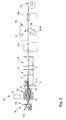
- FIG. 1 shows a garden hose 1, made of plastic, for example polyethylene, which has, at regular intervals, holes or discharge ports 2, through which water can flow to water plants (not shown). At around the holes 2 are placed inside the pipe, and thus not visible since the outside, drippers 4 whose structure is explained with the help of Figure 2.
- plastic for example polyethylene
- the dripper is a piece of plastic material, in principle composition than that of pipe 1, although this is not mandatory.
- the dripper 4 generally has an elongate parallelepiped shaped body, with a "outer" surface 5, which has a curved shape in cross-section corresponding to the curvature of the inner wall of the pipe 1.
- a collection chamber 6 located in the example represented substantially in an extreme part and which does not reach the opposite face 7 of the dripper.
- a channel 8 forming a labyrinth which connects the collection chamber 6 to a passage 9, located at another end of the dripper 4, which passes through the dripper, to lead to the opposite face, or internal 7 of the dripper.
- the passage 9 and the channel 8 thus form flow means in which a liquid can flow with a low flow rate predetermined between the inner face 7 and the collection chamber 6.
- the dripper 4 is welded, or preferably heat-welded, by all its outer surface 5, on the inside of the pipe 1.
- the water contained inside the tube 1 flows outwards in passing through the passages 9, the channel 8, the collection chamber 6 and the holes 2.
- the dripper 4 according to the invention also comprises a protruding member 10 protruding beyond the outer surface 5 from the bottom 12 of the chamber of
- the protruding member 10 has the shape of a trunk of cone and comes from matter with the dripper.
- the projecting member 10 is moreover made of the same material as the body of the dripper 4.
- the dripper according to the invention can therefore be typically obtained by conventional molding techniques. injection.
- the protruding member 10 could have any other shape when it protrudes above the outer face 5 of the taster. It could also be envisaged that the salient organ not extend directly from the bottom of the collection chamber but a side wall of this room, being always understood to be in such a form that it includes a portion that extends above the outer face 5. According to a variant of embodiment, the protruding member 10 could be returned to the collection chamber 6 and fixed in the latter by any appropriate means such as gluing, welding or similar.
- the protruding height of the protruding member 10 above the surface outer 5 will depend on the thickness of the wall of the pipe on which the dripper must be soldered.
- the projecting member 10 extends between about 2 and 5 mm at above the outer face 5 for pipes having a wall thickness of the order from 0.1 to 1 mm and from 4 to 8 mm for pipes with a wall thickness of the order of 1 to 2 mm.
- the protruding member 10 comprises a free end preferably having a rounded shape.
- the apparatus of manufacture of the tube 1 comprises an extrusion station 20, comprising a chamber of melting 21 of the plastic material, which feeds an assembly 22 provided with a die 23, inside which is provided a conical mandrel 24 arranged in such a way that out of the die a tubular blank 25.
- the blank 25 is pulled by pulling stations 26a, 26b, moving to through a calibration station 27 and cooling chambers 28 and through a PD cutting station which will be described in more detail below. Beyond the post pull 26b, the pipe is wound on a drum 29.
- the mandrel 24 has a passage axial inside which is disposed a guide support 30 comprising a path guide 30a whose free end 30b extends to the inside of the calibrator 27a of calibration station 27.
- the guide support 30 receives drippers 4 from a feeding device 31.
- the dimensions of the guide piece 30 are calculated so that, at this point, the pipe blank 25, whose diameter is reduced by the calibrator 27a, comes into contact with the dripper 4 at the moment when it is still pasty, which ensures the thermo-welding the upper face 5 of the dripper against the inner wall of the blank.
- the calibrator 27a is associated with a pressure roller 34 adjustable in height and rotating at a speed synchronized with the speed of scrolling of the pipe.
- roller 34 presses the pipe and the drippers 4 against the path of guidance 30a.
- pressure roller 34 may also comprise a lining 34a flexible on its surface of contact in order to marry as best as possible the shape that the face 5 of the dripper to the pipe and in particular the shape of the protruding member 10.
- the pipe 1 has on its outer surface and the right of each dripper a protrusion P caused by the crushing of the wall of the pipe on the protruding member 10 and extending above the surface of the outer wall of the pipe.
- the pipe 1 thus shaped enters the PD cutting station, via the first traction station 26a and then leaves to enter the second traction station 26b.
- the speeds of advance of these Traction stations are chosen so that the pipe is sufficiently tight so that it flats optimally in the PD cutting station which will be described below.
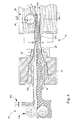
- the pipe 1 enters the cutting station in the direction of the arrow F by passing on a drum 36 and on return pulleys 38, 40 in order to make it pass in front of a cutting tool 42.
- FIGS. 7 to 10 shown in Figure 8 in section the configuration of a section of pipe 1 comprising a dripper 4 just before the entry of the pipe into the PD cutting station. It can be seen that the pipe 1 is flattened and has a hump at the spot of the dripper 4 as well as a protuberance P at the right of the collection chamber 6, the protuberance being caused by the protruding member 10.
- the drum 36 and the pulleys 38, 40 are rotatably mounted on a frame 44 of the cutting station.
- the drum 36 has a cylindrical surface 36a having a width corresponding substantially to several widths of the pipe in its flattened configuration. Note in this connection that this surface 36a can be coated a non-slip layer, for example rubber, to improve the training of the pipe and its maintenance in tension on the drum 36.
- the pipe arrives in an anterior region of the drum 36 on which it winds partially, then is directed to the pulley 38. Since this last the pipe is to again biased towards the drum 36 on which it winds partially in a middle region of the latter.
- the pipe is then redirected to the pulley 40 and since it is again directed obliquely towards the drum 36 on which it partially wraps in a posterior region, from which it leaves the cutting station pulled by the second traction station 26b.
- the drum 26 and the pulleys 38, 40 are rotatably mounted on their respective axes and are consequently driven by the traction stations 26a, 26b. This arrangement allows to reach an optimal tension of the pipe 1 in this position without however lengthening the pipe.
- the cutting tool 42 is a tool rotating rotatably mounted on the frame 44 and whose axis of rotation extends parallel to the axis of rotation A of the drum 36 and substantially aligned with this axis A.
- the tool 42 is typically a cutter whose cutting width is substantially greater than the width of the pipe in its flattened configuration. This tool extends over the cylindrical surface 36a of the drum 36 on the running path of the pipe 1 and at a height H determined from the surface 36a (FIGS. 9a and 9b).
- the cutting tool 42 extends above the middle winding region of the pipe 1 to a sufficient distance from the surface 36a so that the cutting edges of the tool 42 meet the running path of the protuberances P and head them without risking to damage the pipe at the location of the drippers.
- the tool 42 is mounted on the frame so as to be adjustable in height above the surface 36a. It should also be noted that the meaning of rotation R of the rotary tool 42 is such that the cutting direction of the tool is opposite to the direction of movement of the pipe 1.
- the surface 36a forms a cylindrical bearing surface for the pipe 1 for bending the pipe 1 and the dripper 4 at the time of the cutting operation of the protuberances.
- This bending has the advantage of accentuating the projection of the protuberances P and thus of facilitating the cutting operation thereof.
- the tool 42 cuts the upper part of the body protruding which is above the outer face 5 of the dripper 4 and a wall portion of the pipe 1 which covers this member 10.
- the collection chambers 6 are placed in communication with the outside by discharge ports 2 created by elimination of the sections of the pipe covering the projecting members.
- the edge of each discharge port 2 builds, given the elastic nature of the wall of the pipe, on the body of the protruding member 10 of the drippers 4.
- the fluid pressure pushes the edge each orifice 2 of the projecting member 10 and opens a passage for the fluid.
- the edge of each orifice 2 in conjunction with the truncated projecting member 10 thus forms a device flapper allowing in particular to prevent dirt from entering the room collection.
- FIGS. 11a and 11b show a variant embodiment of the cutting of the installation according to the invention in which the elements already described in connection with the preceding figures are designated by the same references digital.
- the cutting tool 42 is formed of a fixed blade whose cutting edge is arranged on the running path of the protuberances P.
- FIGS. 12 and 13 show an alternative embodiment of a pipe irrigation system according to the invention in which the elements already described in connection with the previous figures are designated by the same reference numerals.
- the drippers 4 are not more realized in unitary form, but are connected to each other by their body which is made in one piece in the form of a continuous strip.
- the band includes therefore on its outer surface and at regular intervals a plurality of collection chambers respectively connected to a labyrinth cut into said outer surface and in communication with the inner face of the strip.
- the plurality of drippers thus has a band-shaped common body which can be conveyed, for example from a spool, onto the support guide and brought in contact with the inside of the pipe in the calibrator to achieve the welding or thermo-welding outer surface of the strip to the inside of the pipe as is the case for the welding of unit drippers.
Landscapes
- Engineering & Computer Science (AREA)
- Mechanical Engineering (AREA)
- Life Sciences & Earth Sciences (AREA)
- Physics & Mathematics (AREA)
- Thermal Sciences (AREA)
- Soil Sciences (AREA)
- Water Supply & Treatment (AREA)
- Environmental Sciences (AREA)
- Extrusion Moulding Of Plastics Or The Like (AREA)
- Rigid Pipes And Flexible Pipes (AREA)
Priority Applications (1)
| Application Number | Priority Date | Filing Date | Title |
|---|---|---|---|
| EP04029032A EP1541014B1 (de) | 2003-12-12 | 2004-12-08 | Methode zur Herstellung von Tropfenbewässerungsrohren |
Applications Claiming Priority (3)
| Application Number | Priority Date | Filing Date | Title |
|---|---|---|---|
| EP03028492A EP1541013A1 (de) | 2003-12-12 | 2003-12-12 | Methode zur Herstellung von Tropfenbewässerungsrohren |
| EP03028492 | 2003-12-12 | ||
| EP04029032A EP1541014B1 (de) | 2003-12-12 | 2004-12-08 | Methode zur Herstellung von Tropfenbewässerungsrohren |
Publications (2)
| Publication Number | Publication Date |
|---|---|
| EP1541014A1 true EP1541014A1 (de) | 2005-06-15 |
| EP1541014B1 EP1541014B1 (de) | 2010-02-24 |
Family
ID=34524717
Family Applications (1)
| Application Number | Title | Priority Date | Filing Date |
|---|---|---|---|
| EP04029032A Expired - Lifetime EP1541014B1 (de) | 2003-12-12 | 2004-12-08 | Methode zur Herstellung von Tropfenbewässerungsrohren |
Country Status (1)
| Country | Link |
|---|---|
| EP (1) | EP1541014B1 (de) |
Cited By (8)
| Publication number | Priority date | Publication date | Assignee | Title |
|---|---|---|---|---|
| ES2310952A1 (es) * | 2005-02-23 | 2009-01-16 | Netafim (A.C.S.) Ltd. | Rociador y tuberia de irrigacion. |
| EP2227942A1 (de) * | 2009-03-10 | 2010-09-15 | THE Thomas Machines S.A. | Vorrichtung zur Herstellung eines Tropfbewässerungsrohres |
| WO2012038766A2 (en) | 2010-09-20 | 2012-03-29 | Emmanuil Dermitzakis | Emitter and method for opening water outlet openings |
| WO2012120317A2 (en) | 2011-03-10 | 2012-09-13 | Emmanuil Dermitzakis | Lateral union base for receiving water from an irrigation pipe |
| WO2013030606A2 (en) | 2011-08-29 | 2013-03-07 | Emmanuil Dermitzakis | Method for the production of an irrigation pipe |
| WO2016059441A2 (en) | 2014-10-13 | 2016-04-21 | Emmanuil Dermitzakis | Hybrid emitter and method of integrating emitters and accessories within irrigation pipe |
| CN104488666B (zh) * | 2014-12-30 | 2016-09-28 | 苏芳 | 一种专用迷宫条、薄壁滴灌管/带及其加工方法 |
| CN120962979A (zh) * | 2025-10-23 | 2025-11-18 | 大禹节水集团股份有限公司 | 一种外镶贴片式滴灌带的生产装置 |
Citations (3)
| Publication number | Priority date | Publication date | Assignee | Title |
|---|---|---|---|---|
| EP0344605A2 (de) | 1988-05-30 | 1989-12-06 | Hydro-Plan Engineering Ltd. | Verfahren und Anlage zur Herstellung einer Tropfen-Bewässerungsleitung |
| WO1992005689A1 (de) * | 1990-10-03 | 1992-04-16 | Emmanuil Dermitzakis | Bewässerungsrohr mit innengeschweissten tropfelementen und methode zu seiner herstellung |
| EP0715926A1 (de) | 1994-12-07 | 1996-06-12 | E. Kertscher S.A. | Verfahren zur Herstellung von Rohren zur tropfenweisen Bewässerung |
-
2004
- 2004-12-08 EP EP04029032A patent/EP1541014B1/de not_active Expired - Lifetime
Patent Citations (3)
| Publication number | Priority date | Publication date | Assignee | Title |
|---|---|---|---|---|
| EP0344605A2 (de) | 1988-05-30 | 1989-12-06 | Hydro-Plan Engineering Ltd. | Verfahren und Anlage zur Herstellung einer Tropfen-Bewässerungsleitung |
| WO1992005689A1 (de) * | 1990-10-03 | 1992-04-16 | Emmanuil Dermitzakis | Bewässerungsrohr mit innengeschweissten tropfelementen und methode zu seiner herstellung |
| EP0715926A1 (de) | 1994-12-07 | 1996-06-12 | E. Kertscher S.A. | Verfahren zur Herstellung von Rohren zur tropfenweisen Bewässerung |
Cited By (13)
| Publication number | Priority date | Publication date | Assignee | Title |
|---|---|---|---|---|
| ES2310952B2 (es) * | 2005-02-23 | 2010-02-09 | Netafim Ltd. | Rociador y tuberia de irrigacion. |
| US7681805B2 (en) | 2005-02-23 | 2010-03-23 | Netafim, Ltd. | Irrigation dripper and pipe |
| ES2310952A1 (es) * | 2005-02-23 | 2009-01-16 | Netafim (A.C.S.) Ltd. | Rociador y tuberia de irrigacion. |
| US8475617B2 (en) | 2009-03-10 | 2013-07-02 | The Machines Yvonand Sa | Device for production of drip irrigation tubes |
| EP2227942A1 (de) * | 2009-03-10 | 2010-09-15 | THE Thomas Machines S.A. | Vorrichtung zur Herstellung eines Tropfbewässerungsrohres |
| US9433157B2 (en) | 2010-09-20 | 2016-09-06 | Emmanuil Dermitzakis | Emitter and method for opening water outlet openings |
| WO2012038766A2 (en) | 2010-09-20 | 2012-03-29 | Emmanuil Dermitzakis | Emitter and method for opening water outlet openings |
| WO2012120317A2 (en) | 2011-03-10 | 2012-09-13 | Emmanuil Dermitzakis | Lateral union base for receiving water from an irrigation pipe |
| WO2013030606A2 (en) | 2011-08-29 | 2013-03-07 | Emmanuil Dermitzakis | Method for the production of an irrigation pipe |
| WO2016059441A2 (en) | 2014-10-13 | 2016-04-21 | Emmanuil Dermitzakis | Hybrid emitter and method of integrating emitters and accessories within irrigation pipe |
| CN104488666B (zh) * | 2014-12-30 | 2016-09-28 | 苏芳 | 一种专用迷宫条、薄壁滴灌管/带及其加工方法 |
| CN120962979A (zh) * | 2025-10-23 | 2025-11-18 | 大禹节水集团股份有限公司 | 一种外镶贴片式滴灌带的生产装置 |
| CN120962979B (zh) * | 2025-10-23 | 2026-01-23 | 大禹节水集团股份有限公司 | 一种外镶贴片式滴灌带的生产装置 |
Also Published As
| Publication number | Publication date |
|---|---|
| EP1541014B1 (de) | 2010-02-24 |
Similar Documents
| Publication | Publication Date | Title |
|---|---|---|
| EP1541013A1 (de) | Methode zur Herstellung von Tropfenbewässerungsrohren | |
| EP1817955B2 (de) | Anlage und Verfahren zur Herstellung von Röhren zur tropfenweisen Bewässerung | |
| EP0715926B1 (de) | Verfahren zur Herstellung von Rohren zur tropfenweisen Bewässerung | |
| EP0970602B1 (de) | Verfahren zur Herstellung eines Tropfbewässerungsschlauches und Produktionslinie zu seiner Durchführung | |
| EP0872172B1 (de) | Verfahren zum Herstellen eines Tropfbewässerungsschlauches und Tropfer zum Verwenden in einem derartigen Schlauch | |
| EP1268158B1 (de) | Verfahren und fertigungsstrasse zur kontinuierlichen herstellung von biaxial-gereckten kunststoffrohren | |
| EP0242327A2 (de) | Verfahren zur Herstellung eines Schlauches zur Tropfbewässerung und durch dieses Verfahren hergestellter Bewässerungsschlauch | |
| EP1701147A1 (de) | Vorrichtung zur Herstellung von Schläuchen und entsprechendes Verfahren zur Fehlerermittlung | |
| FR2609932A1 (fr) | Procede et dispositif pour l'extrusion de tubes en matiere plastique avec formation des extremites en forme de manchon | |
| FR2479663A1 (fr) | Procede pour fabriquer un filtre unitaire pour cigarettes et dispositif pour la mise en oeuvre de ce procede | |
| EP1541014B1 (de) | Methode zur Herstellung von Tropfenbewässerungsrohren | |
| FR2770487A1 (fr) | Machine de formation, remplissage et fermeture automatique de sacs, a profiles de fermeture transversaux | |
| EP1905570A1 (de) | Verfahren und Vorrichtung zum internen Schweissen von Kunststoffrohren | |
| FR2547766A1 (fr) | Procede et appareil de fabrication de tubes ondules | |
| FR2467161A1 (fr) | Dispositif de guidage de bande destine en particulier aux machines de fabrication de cigarettes | |
| FR2655947A1 (fr) | Dispositif pour l'application de bandes a des paquets sensiblement parallelepipediques. | |
| CH416072A (fr) | Procédé de fabrication d'un tube flexible en matière thermoplastique armée de longuer indéfinie, et appareil pour la mise en oeuvre de ce procédé | |
| FR2489096A1 (fr) | Procede et appareil de mise en forme d'une pate, et mecanisme d'alimentation, dispositif de separation et dispositif de decoupe pour un tel appareil | |
| EP1239724A1 (de) | Verfahren zur gleichzeitigen herstellung von zumindest zwei tropfbewässerungsschläuchen | |
| EP1339274B1 (de) | Herstellungslinie für einen tropfbewässerungsschlauch und verfahren zur benutzung dieser linie | |
| EP1602273B1 (de) | Vorrichtung zur Herstellung von Bewässerungsrohren zur Tropfbewässerung | |
| EP1600406B1 (de) | Anlage zum Herstellen von Tropfbewässerungsschläuchen | |
| FR2806957A1 (fr) | Procede et ligne pour fabriquer en continu des tubes en matiere plastique avec etirage bi-axial, et tube en matiere plastique obtenu | |
| FR2656290A1 (fr) | Dispositif de separation et d'evacuation de chutes decoupees dans une bande de materiau. | |
| FR2880329A1 (fr) | Procede et dispositif de raccordement de deux gaines tubulaires aplaties dans une machine de pose de manchons sur des objets en defilement |
Legal Events
| Date | Code | Title | Description |
|---|---|---|---|
| PUAI | Public reference made under article 153(3) epc to a published international application that has entered the european phase |
Free format text: ORIGINAL CODE: 0009012 |
|
| AK | Designated contracting states |
Kind code of ref document: A1 Designated state(s): AT BE BG CH CY CZ DE DK EE ES FI FR GB GR HU IE IS IT LI LT LU MC NL PL PT RO SE SI SK TR |
|
| AX | Request for extension of the european patent |
Extension state: AL BA HR LV MK YU |
|
| 17P | Request for examination filed |
Effective date: 20051215 |
|
| AKX | Designation fees paid |
Designated state(s): AT BE BG CH CY CZ DE DK EE ES FI FR GB GR HU IE IS IT LI LT LU MC NL PL PT RO SE SI SK TR |
|
| GRAP | Despatch of communication of intention to grant a patent |
Free format text: ORIGINAL CODE: EPIDOSNIGR1 |
|
| GRAS | Grant fee paid |
Free format text: ORIGINAL CODE: EPIDOSNIGR3 |
|
| GRAC | Information related to communication of intention to grant a patent modified |
Free format text: ORIGINAL CODE: EPIDOSCIGR1 |
|
| GRAL | Information related to payment of fee for publishing/printing deleted |
Free format text: ORIGINAL CODE: EPIDOSDIGR3 |
|
| GRAS | Grant fee paid |
Free format text: ORIGINAL CODE: EPIDOSNIGR3 |
|
| GRAA | (expected) grant |
Free format text: ORIGINAL CODE: 0009210 |
|
| AK | Designated contracting states |
Kind code of ref document: B1 Designated state(s): AT BE BG CH CY CZ DE DK EE ES FI FR GB GR HU IE IS IT LI LT LU MC NL PL PT RO SE SI SK TR |
|
| REG | Reference to a national code |
Ref country code: GB Ref legal event code: FG4D Free format text: NOT ENGLISH |
|
| REG | Reference to a national code |
Ref country code: CH Ref legal event code: EP |
|
| REG | Reference to a national code |
Ref country code: IE Ref legal event code: FG4D Free format text: LANGUAGE OF EP DOCUMENT: FRENCH |
|
| REF | Corresponds to: |
Ref document number: 602004025662 Country of ref document: DE Date of ref document: 20100408 Kind code of ref document: P |
|
| RAP2 | Party data changed (patent owner data changed or rights of a patent transferred) |
Owner name: THE MACHINES YVONAND SA |
|
| REG | Reference to a national code |
Ref country code: CH Ref legal event code: NV Representative=s name: ICB INGENIEURS CONSEILS EN BREVETS SA |
|
| REG | Reference to a national code |
Ref country code: GR Ref legal event code: EP Ref document number: 20100401177 Country of ref document: GR |
|
| REG | Reference to a national code |
Ref country code: ES Ref legal event code: FG2A Ref document number: 2341243 Country of ref document: ES Kind code of ref document: T3 |
|
| REG | Reference to a national code |
Ref country code: NL Ref legal event code: VDEP Effective date: 20100224 |
|
| LTIE | Lt: invalidation of european patent or patent extension |
Effective date: 20100224 |
|
| PG25 | Lapsed in a contracting state [announced via postgrant information from national office to epo] |
Ref country code: LT Free format text: LAPSE BECAUSE OF FAILURE TO SUBMIT A TRANSLATION OF THE DESCRIPTION OR TO PAY THE FEE WITHIN THE PRESCRIBED TIME-LIMIT Effective date: 20100224 Ref country code: IS Free format text: LAPSE BECAUSE OF FAILURE TO SUBMIT A TRANSLATION OF THE DESCRIPTION OR TO PAY THE FEE WITHIN THE PRESCRIBED TIME-LIMIT Effective date: 20100624 Ref country code: PT Free format text: LAPSE BECAUSE OF FAILURE TO SUBMIT A TRANSLATION OF THE DESCRIPTION OR TO PAY THE FEE WITHIN THE PRESCRIBED TIME-LIMIT Effective date: 20100625 |
|
| REG | Reference to a national code |
Ref country code: FR Ref legal event code: CA Ref country code: FR Ref legal event code: CD |
|
| PG25 | Lapsed in a contracting state [announced via postgrant information from national office to epo] |
Ref country code: FI Free format text: LAPSE BECAUSE OF FAILURE TO SUBMIT A TRANSLATION OF THE DESCRIPTION OR TO PAY THE FEE WITHIN THE PRESCRIBED TIME-LIMIT Effective date: 20100224 Ref country code: SI Free format text: LAPSE BECAUSE OF FAILURE TO SUBMIT A TRANSLATION OF THE DESCRIPTION OR TO PAY THE FEE WITHIN THE PRESCRIBED TIME-LIMIT Effective date: 20100224 Ref country code: PL Free format text: LAPSE BECAUSE OF FAILURE TO SUBMIT A TRANSLATION OF THE DESCRIPTION OR TO PAY THE FEE WITHIN THE PRESCRIBED TIME-LIMIT Effective date: 20100224 |
|
| REG | Reference to a national code |
Ref country code: IE Ref legal event code: FD4D |
|
| PG25 | Lapsed in a contracting state [announced via postgrant information from national office to epo] |
Ref country code: IE Free format text: LAPSE BECAUSE OF FAILURE TO SUBMIT A TRANSLATION OF THE DESCRIPTION OR TO PAY THE FEE WITHIN THE PRESCRIBED TIME-LIMIT Effective date: 20100224 Ref country code: SE Free format text: LAPSE BECAUSE OF FAILURE TO SUBMIT A TRANSLATION OF THE DESCRIPTION OR TO PAY THE FEE WITHIN THE PRESCRIBED TIME-LIMIT Effective date: 20100224 Ref country code: RO Free format text: LAPSE BECAUSE OF FAILURE TO SUBMIT A TRANSLATION OF THE DESCRIPTION OR TO PAY THE FEE WITHIN THE PRESCRIBED TIME-LIMIT Effective date: 20100224 Ref country code: NL Free format text: LAPSE BECAUSE OF FAILURE TO SUBMIT A TRANSLATION OF THE DESCRIPTION OR TO PAY THE FEE WITHIN THE PRESCRIBED TIME-LIMIT Effective date: 20100224 Ref country code: EE Free format text: LAPSE BECAUSE OF FAILURE TO SUBMIT A TRANSLATION OF THE DESCRIPTION OR TO PAY THE FEE WITHIN THE PRESCRIBED TIME-LIMIT Effective date: 20100224 |
|
| PG25 | Lapsed in a contracting state [announced via postgrant information from national office to epo] |
Ref country code: BG Free format text: LAPSE BECAUSE OF FAILURE TO SUBMIT A TRANSLATION OF THE DESCRIPTION OR TO PAY THE FEE WITHIN THE PRESCRIBED TIME-LIMIT Effective date: 20100524 Ref country code: CZ Free format text: LAPSE BECAUSE OF FAILURE TO SUBMIT A TRANSLATION OF THE DESCRIPTION OR TO PAY THE FEE WITHIN THE PRESCRIBED TIME-LIMIT Effective date: 20100224 Ref country code: SK Free format text: LAPSE BECAUSE OF FAILURE TO SUBMIT A TRANSLATION OF THE DESCRIPTION OR TO PAY THE FEE WITHIN THE PRESCRIBED TIME-LIMIT Effective date: 20100224 |
|
| PLBE | No opposition filed within time limit |
Free format text: ORIGINAL CODE: 0009261 |
|
| STAA | Information on the status of an ep patent application or granted ep patent |
Free format text: STATUS: NO OPPOSITION FILED WITHIN TIME LIMIT |
|
| PG25 | Lapsed in a contracting state [announced via postgrant information from national office to epo] |
Ref country code: DK Free format text: LAPSE BECAUSE OF FAILURE TO SUBMIT A TRANSLATION OF THE DESCRIPTION OR TO PAY THE FEE WITHIN THE PRESCRIBED TIME-LIMIT Effective date: 20100224 |
|
| 26N | No opposition filed |
Effective date: 20101125 |
|
| BERE | Be: lapsed |
Owner name: THE THOMAS MACHINES S.A Effective date: 20101231 |
|
| PG25 | Lapsed in a contracting state [announced via postgrant information from national office to epo] |
Ref country code: MC Free format text: LAPSE BECAUSE OF NON-PAYMENT OF DUE FEES Effective date: 20101231 |
|
| GBPC | Gb: european patent ceased through non-payment of renewal fee |
Effective date: 20101208 |
|
| PG25 | Lapsed in a contracting state [announced via postgrant information from national office to epo] |
Ref country code: CY Free format text: LAPSE BECAUSE OF NON-PAYMENT OF DUE FEES Effective date: 20101208 |
|
| REG | Reference to a national code |
Ref country code: FR Ref legal event code: ST Effective date: 20110831 |
|
| PG25 | Lapsed in a contracting state [announced via postgrant information from national office to epo] |
Ref country code: BE Free format text: LAPSE BECAUSE OF NON-PAYMENT OF DUE FEES Effective date: 20101231 |
|
| PG25 | Lapsed in a contracting state [announced via postgrant information from national office to epo] |
Ref country code: FR Free format text: LAPSE BECAUSE OF NON-PAYMENT OF DUE FEES Effective date: 20110103 |
|
| REG | Reference to a national code |
Ref country code: DE Ref legal event code: R119 Ref document number: 602004025662 Country of ref document: DE Effective date: 20110701 |
|
| PG25 | Lapsed in a contracting state [announced via postgrant information from national office to epo] |
Ref country code: GB Free format text: LAPSE BECAUSE OF NON-PAYMENT OF DUE FEES Effective date: 20101208 Ref country code: DE Free format text: LAPSE BECAUSE OF NON-PAYMENT OF DUE FEES Effective date: 20110701 Ref country code: GR Free format text: LAPSE BECAUSE OF NON-PAYMENT OF DUE FEES Effective date: 20110704 |
|
| PG25 | Lapsed in a contracting state [announced via postgrant information from national office to epo] |
Ref country code: IT Free format text: LAPSE BECAUSE OF NON-PAYMENT OF DUE FEES Effective date: 20101208 |
|
| REG | Reference to a national code |
Ref country code: ES Ref legal event code: FD2A Effective date: 20120206 |
|
| PG25 | Lapsed in a contracting state [announced via postgrant information from national office to epo] |
Ref country code: ES Free format text: LAPSE BECAUSE OF NON-PAYMENT OF DUE FEES Effective date: 20101209 |
|
| PG25 | Lapsed in a contracting state [announced via postgrant information from national office to epo] |
Ref country code: HU Free format text: LAPSE BECAUSE OF FAILURE TO SUBMIT A TRANSLATION OF THE DESCRIPTION OR TO PAY THE FEE WITHIN THE PRESCRIBED TIME-LIMIT Effective date: 20100825 Ref country code: LU Free format text: LAPSE BECAUSE OF NON-PAYMENT OF DUE FEES Effective date: 20101208 |
|
| PG25 | Lapsed in a contracting state [announced via postgrant information from national office to epo] |
Ref country code: TR Free format text: LAPSE BECAUSE OF FAILURE TO SUBMIT A TRANSLATION OF THE DESCRIPTION OR TO PAY THE FEE WITHIN THE PRESCRIBED TIME-LIMIT Effective date: 20100224 |
|
| PGFP | Annual fee paid to national office [announced via postgrant information from national office to epo] |
Ref country code: AT Payment date: 20181121 Year of fee payment: 15 |
|
| PGFP | Annual fee paid to national office [announced via postgrant information from national office to epo] |
Ref country code: CH Payment date: 20181126 Year of fee payment: 15 |
|
| REG | Reference to a national code |
Ref country code: CH Ref legal event code: PL |
|
| REG | Reference to a national code |
Ref country code: AT Ref legal event code: MM01 Ref document number: 458401 Country of ref document: AT Kind code of ref document: T Effective date: 20191208 |
|
| PG25 | Lapsed in a contracting state [announced via postgrant information from national office to epo] |
Ref country code: AT Free format text: LAPSE BECAUSE OF NON-PAYMENT OF DUE FEES Effective date: 20191208 Ref country code: LI Free format text: LAPSE BECAUSE OF NON-PAYMENT OF DUE FEES Effective date: 20191231 Ref country code: CH Free format text: LAPSE BECAUSE OF NON-PAYMENT OF DUE FEES Effective date: 20191231 |