EP1540950B1 - Trick mode using dummy bidirectional predictive pictures - Google Patents
Trick mode using dummy bidirectional predictive pictures Download PDFInfo
- Publication number
- EP1540950B1 EP1540950B1 EP03764390A EP03764390A EP1540950B1 EP 1540950 B1 EP1540950 B1 EP 1540950B1 EP 03764390 A EP03764390 A EP 03764390A EP 03764390 A EP03764390 A EP 03764390A EP 1540950 B1 EP1540950 B1 EP 1540950B1
- Authority
- EP
- European Patent Office
- Prior art keywords
- video signal
- picture
- pictures
- progressively scanned
- scanned original
- Prior art date
- Legal status (The legal status is an assumption and is not a legal conclusion. Google has not performed a legal analysis and makes no representation as to the accuracy of the status listed.)
- Expired - Lifetime
Links
- 230000002457 bidirectional effect Effects 0.000 title claims abstract description 26
- 238000000034 method Methods 0.000 claims abstract description 21
- 238000012544 monitoring process Methods 0.000 claims abstract description 4
- 230000002123 temporal effect Effects 0.000 claims description 34
- 238000003780 insertion Methods 0.000 claims description 8
- 230000037431 insertion Effects 0.000 claims description 8
- 230000011664 signaling Effects 0.000 claims 2
- 230000005540 biological transmission Effects 0.000 description 8
- 238000006243 chemical reaction Methods 0.000 description 2
- 238000013500 data storage Methods 0.000 description 2
- 238000010586 diagram Methods 0.000 description 2
- 230000003287 optical effect Effects 0.000 description 2
- 102100037812 Medium-wave-sensitive opsin 1 Human genes 0.000 description 1
- 230000001154 acute effect Effects 0.000 description 1
- 238000011161 development Methods 0.000 description 1
- 230000018109 developmental process Effects 0.000 description 1
- 238000012986 modification Methods 0.000 description 1
- 230000004048 modification Effects 0.000 description 1
- 230000005236 sound signal Effects 0.000 description 1
- 239000013598 vector Substances 0.000 description 1
Images
Classifications
-
- H—ELECTRICITY
- H04—ELECTRIC COMMUNICATION TECHNIQUE
- H04N—PICTORIAL COMMUNICATION, e.g. TELEVISION
- H04N5/00—Details of television systems
- H04N5/76—Television signal recording
- H04N5/78—Television signal recording using magnetic recording
- H04N5/782—Television signal recording using magnetic recording on tape
- H04N5/783—Adaptations for reproducing at a rate different from the recording rate
-
- H—ELECTRICITY
- H04—ELECTRIC COMMUNICATION TECHNIQUE
- H04N—PICTORIAL COMMUNICATION, e.g. TELEVISION
- H04N5/00—Details of television systems
- H04N5/76—Television signal recording
- H04N5/91—Television signal processing therefor
- H04N5/93—Regeneration of the television signal or of selected parts thereof
-
- H—ELECTRICITY
- H04—ELECTRIC COMMUNICATION TECHNIQUE
- H04N—PICTORIAL COMMUNICATION, e.g. TELEVISION
- H04N19/00—Methods or arrangements for coding, decoding, compressing or decompressing digital video signals
- H04N19/50—Methods or arrangements for coding, decoding, compressing or decompressing digital video signals using predictive coding
- H04N19/503—Methods or arrangements for coding, decoding, compressing or decompressing digital video signals using predictive coding involving temporal prediction
- H04N19/51—Motion estimation or motion compensation
-
- H—ELECTRICITY
- H04—ELECTRIC COMMUNICATION TECHNIQUE
- H04N—PICTORIAL COMMUNICATION, e.g. TELEVISION
- H04N5/00—Details of television systems
- H04N5/76—Television signal recording
- H04N5/765—Interface circuits between an apparatus for recording and another apparatus
- H04N5/775—Interface circuits between an apparatus for recording and another apparatus between a recording apparatus and a television receiver
-
- H—ELECTRICITY
- H04—ELECTRIC COMMUNICATION TECHNIQUE
- H04N—PICTORIAL COMMUNICATION, e.g. TELEVISION
- H04N5/00—Details of television systems
- H04N5/76—Television signal recording
- H04N5/91—Television signal processing therefor
-
- H—ELECTRICITY
- H04—ELECTRIC COMMUNICATION TECHNIQUE
- H04N—PICTORIAL COMMUNICATION, e.g. TELEVISION
- H04N9/00—Details of colour television systems
- H04N9/79—Processing of colour television signals in connection with recording
- H04N9/80—Transformation of the television signal for recording, e.g. modulation, frequency changing; Inverse transformation for playback
- H04N9/804—Transformation of the television signal for recording, e.g. modulation, frequency changing; Inverse transformation for playback involving pulse code modulation of the colour picture signal components
- H04N9/8042—Transformation of the television signal for recording, e.g. modulation, frequency changing; Inverse transformation for playback involving pulse code modulation of the colour picture signal components involving data reduction
Definitions
- Document US 2002/0016970 A1 discloses a data distribution system including a server apparatus and a decoding terminal.
- the access unit information of data to be transmitted is read from a data storage unit in accordance with a trick play request.
- the access unit information is converted for a trick play in a data conversion unit.
- This unit determines, based on the picture type included in the access unit information, the number of repeat pictures which must be inserted in order to maintain the presentation order of the access unit.
- the data size of the repeat pictures can be uniquely determined based on delay values of different access units and the input rate of the video data.
- a dummy B picture is a picture that can be predicted from certain pictures and whose motion vectors and discrete cosine transform (DCT) coefficients are set to zero. As such, a dummy B picture contains very little information.
- a dummy B picture's primary purpose is to duplicate or repeat the picture from which it was predicted using very few bits.
- a dummy B picture is suitable for replacing certain original pictures when those original pictures are to be repeated in the trick mode video signal.
- the dummy B pictures can replace one or more of the repeated original pictures such that the dummy B pictures can be transmitted to a remote decoder rather than certain repeated original pictures. This insertion and replacement step may be helpful in keeping a bit rate of the trick mode video signal stream at a manageable level, as such video signals tend to be elevated because numerous original pictures, particularly those with a large number of bits, are likely to be repeated during the trick mode command.
Landscapes
- Engineering & Computer Science (AREA)
- Multimedia (AREA)
- Signal Processing (AREA)
- Television Signal Processing For Recording (AREA)
- Compression Or Coding Systems Of Tv Signals (AREA)
Abstract
Description
- The inventive arrangements relate generally to video systems and more particularly to video systems that record or replay digitally encoded video sequences.
- Digital television (DTV) and high-definition television (HDTV) are gaining popularity in today's consumer electronics marketplace. Many purchasers of these types of television products often buy digital video recorders or players, such as digital video disc (DVD) recorders or players, for purposes of viewing prerecorded programming or recording their favorite programs. Notably, the combination of a DTV (or an HDTV) and a digital video recorder or player can be an integral part of a home theater entertainment system.
- A digital video recorder or player typically contains a Moving Pictures Expert Group (MPEG) decoder to decode the digitally encoded multimedia data that is stored on the discs that the recorder or player plays. If the digital video recorder or player is connected to a conventional (non-DTV or non-HDTV) television display device, the digitally encoded signal will be decoded by the digital video recorder or player's MPEG decoder before being displayed on the conventional television display. Significantly, however, many DTV's contain their own MPEG decoders, as the MPEG decoder in the majority of digital video recorders or players cannot handle the stringent requirements for decoding video signals for such televisions receivers As such, if a digital video recorder or player is connected to a DTV, the video signal read from the disc is remotely decoded by the DTV's decoder. This configuration can be referred to as a remote decoder arrangement.
- There is, however, an important disadvantage to decoding digitally encoded signals with a remote DTV decoder. Namely, it is very difficult to perform trick modes in this type of arrangement. A trick mode can be any playback of a video or audio signal at any speed other than normal speed or in other than a forward direction. Oftentimes, a trick mode involves repeating a number of pictures in a video signal such as during a slow motion trick mode. However, since the bandwidth between the digital video recorder or player and the digital television display can be limited, repeating pictures in the signal being fed to the display may cause the signal to exceed the maximum bit rate limit of the transmission channel. The problem is even more acute if the pictures are intra (I) pictures or predictive (P) pictures, since these pictures are generally encoded with more bits. Thus, a need exists for a method and system for performing a trick mode in a remote decoder arrangement without exceeding a maximum bit rate limit and without increasing system costs or complexity.
- Document
US 2002/0016970 A1 discloses a data distribution system including a server apparatus and a decoding terminal. In the server apparatus, the access unit information of data to be transmitted is read from a data storage unit in accordance with a trick play request. The access unit information is converted for a trick play in a data conversion unit. This unit determines, based on the picture type included in the access unit information, the number of repeat pictures which must be inserted in order to maintain the presentation order of the access unit. The data size of the repeat pictures can be uniquely determined based on delay values of different access units and the input rate of the video data. - Furthermore, document
WO 97/19559 A1 - Document
US 2002/0016970 A1 discloses a data distribution system including a server apparatus and a decoding terminal. In the server apparatus, the access unit information of data to be transmitted is read from a data storage unit in accordance with a trick play request. The access unit information is converted for a trick play in a data conversion unit. This unit determines, based on the picture type included in the access unit information, the number of repeat pictures which must be inserted in order to maintain the presentation order of the access unit. The data size of the repeat pictures can be uniquely determined based on delay values of different access units and the input rate of the video data. - Furthermore, document
WO 97/19559 A1 - The present invention concerns a method according to claim 1. Additionally, the present invention concerns a system according to claim 8. Further developments of the present invention are defined in the subclaims.
- The display indicator can be a temporal reference field. In addition, each temporal reference field can have an integer value, and the step of selectively modifying the temporal reference field of at least a portion of the plurality of original pictures can include the step of incrementally increasing by one the integer value of the temporal reference field each time an original picture is repeated and each time a dummy bidirectional predictive picture is substituted for at least one of the repeated original pictures in the video signal.
- In one arrangement, the dummy bidirectional predictive picture can be predicted from a reference picture. Further, the reference picture can be an intra picture or a predictive picture. In another arrangement, at least a portion of the trick mode video signal can be decoded by a remote decoder.
-
-
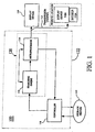
FIGURE 1 is a block diagram of a system that can perform a trick mode using dummy bidirectional predictive pictures in accordance with the inventive arrangements herein. -
FIGURE 2 is a flow chart that illustrates an operation of performing a trick mode using dummy bidirectional predictive pictures in accordance with the inventive arrangements. -
FIGURE 3 is a flow chart that illustrates an alternative operation of performing a trick mode using dummy bidirectional predictive pictures in accordance with the inventive arrangements. - A
system 100 for implementing the various advanced operating features in accordance with the inventive arrangements is shown in block diagram form inFIGURE 1 . The invention, however, is not limited to the particular system illustrated inFIGURE 1 , as the invention can be practiced with any other system capable of receiving a digitally encoded signal and transferring that signal to a display device. In addition, thesystem 100 is not limited to reading data from or writing data to any particular type of storage medium, as any storage medium capable of storing digitally encoded data can be used with thesystem 100. - The
system 100 can include acontroller 110 for reading data from and writing data to astorage medium 112. Thesystem 100 can also have asearching engine 114, amicroprocessor 116 and adisplay device 118. Thesearching engine 114 can contain suitable software and circuitry for locating one or more particular types of pictures in a video signal representative stream read from thestorage medium 112. Control and data interfaces can also be provided for permitting themicroprocessor 116 to control the operation of thecontroller 110 and thesearching engine 114. Suitable software or firmware can be provided in memory for the conventional operations performed by themicroprocessor 116. Further, program routines can be provided for themicroprocessor 116 in accordance with the inventive arrangements. - It should be understood that all or portions of the
searching engine 114 and themicroprocessor 116 can be avideo processor 120 within contemplation of the present invention. Further, all or portions of thecontroller 110, thesearching engine 114 and themicroprocessor 116 can be abitstream source 122 within contemplation of the present invention. In one arrangement, adisplay device 118A can contain its own decoder119A for decoding all or a portion of any video signal read from thestorage medium 112 and processed by thebitstream source 122. In this particular arrangement, a decoder (not shown) in thebitstream source 122 typically does not decode the video signal read from thestorage medium 112. In this particular embodiment atransmission channel 117 supplies the processed bitstream to displaydevice 118A and decoder119A and can be referred to as a remote decoder arrangement. It should be noted, however, that the invention is not limited to this arrangement, as the invention can be practiced in other suitable systems. - In operation, the
controller 110 can read a video signal containing a plurality of progressively scanned original pictures from thestorage medium 112. For convenience, the phrase "progressively scanned original pictures" will be shortened to "original pictures" throughout the application. In one arrangement, if themicroprocessor 116 receives a trick mode command such as a slow motion or freeze command, then themicroprocessor 116 can selectively repeat at least one of the original pictures to convert the video signal to a trick mode video signal. Thus, the trick mode video signal can contain the original pictures as well as duplicates of certain original pictures, or repeated original pictures. - In addition, during the trick mode command, the
microprocessor 116, can signal the searchingengine 114 to locate one or more suitable original pictures in the trick mode video signal. Once a suitable original picture is located, the searchingengine 114 can signal themicroprocessor 116, and themicroprocessor 116 can generate a corresponding dummy bidirectional predictive (B) picture. Themicroprocessor 116 can then selectively insert at least one of the corresponding dummy B pictures such that the dummy B picture is sent to thedisplay device 118. In this arrangement, the dummy B pictures can take the place of one or more of the repeated original pictures such that the dummy B picture is transmitted to thedisplay device 118 and displayed instead of a repeated original picture. It is understood, however, that in lieu of repeating pictures in addition to inserting dummy B pictures, themicroprocessor 116 can merely insert dummy B pictures into the video signal read from thestorage medium 112 to form a trick mode video signal. - In another aspect of the invention, the
microprocessor 116 can monitor the bit rate of the trick mode video signal. If the bit rate of the trick mode video signal exceeds a predetermined threshold, then themicroprocessor 116, in conjunction with the searchingengine 114, can perform the selectively inserting step discussed above in which at least one dummy B picture can be inserted in the trick mode video signal. - In another arrangement, the
microprocessor 116 can modify certain portions of information contained within one or more of the plurality of original pictures contained in the trick mode video signal to reflect an intended display order. This modification step can be performed whether original pictures are repeated or dummy B pictures are inserted in the video signal. The overall operation of the invention will be discussed in greater detail below. -
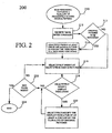
FIGURE 2 illustrates aflowchart 200 that demonstrates one way in which a trick mode using dummy B pictures can be performed. In one arrangement, the invention can be practiced in a remote decoder arrangement. For purposes of the invention, a remote decoder arrangement can be any system in which at least a portion of the pictures in a video signal can be decoded by a decoder that is external to and not under the control of a bitstream source that is providing the pictures to the decoder. As an example, the bitstream source can be an optical storage medium player or recorder, such as a digital video player or recorder, that reads multimedia data from an optical storage medium and transfers this data over a transmission channel to a digital television device, which contains its own decoder. It is understood, however, that the invention is not limited to this example or even a remote decoder arrangement, as the invention can be practiced in any other suitable system or arrangement. - At
step 210, a video signal containing a plurality of progressively scanned original pictures can be read. Atstep 212, a trick mode command can be received. For purposes of the invention, the trick mode command can be any command in which one or more of the original pictures are to be repeated including a pause or freeze command or a slow motion command. As shown atdecision block 213, it can be determined whether at least one of the original pictures is to be repeated. If so, then at least one of the original pictures can be selectively repeated, as shown atstep 214. This selective repetition converts the video signal to a trick mode video signal. - If the original pictures are not to be repeated, then the
flowchart 200 can continue atstep 216 where one or more dummy B pictures can be selectively inserted in the video signal to form a trick mode video signal. In one arrangement, the insertion of the dummy B pictures can form a slow motion trick mode video signal. In addition, if original pictures are repeated in accordance withstep 214, then one or more dummy B pictures can also be selectively inserted into the trick mode video signal containing the repeated original pictures. Thus, the trick mode video signal can contain repeated original pictures, dummy B pictures or a combination thereof. - A dummy B picture is a picture that can be predicted from certain pictures and whose motion vectors and discrete cosine transform (DCT) coefficients are set to zero. As such, a dummy B picture contains very little information. A dummy B picture's primary purpose is to duplicate or repeat the picture from which it was predicted using very few bits. Thus, a dummy B picture is suitable for replacing certain original pictures when those original pictures are to be repeated in the trick mode video signal. In one arrangement, the dummy B pictures can replace one or more of the repeated original pictures such that the dummy B pictures can be transmitted to a remote decoder rather than certain repeated original pictures. This insertion and replacement step may be helpful in keeping a bit rate of the trick mode video signal stream at a manageable level, as such video signals tend to be elevated because numerous original pictures, particularly those with a large number of bits, are likely to be repeated during the trick mode command.
- A picture from which a dummy B picture is predicted is commonly referred to as a reference picture, and a number of the original pictures can be reference pictures. The reference picture can be either an I picture or a P picture. Since pictures cannot be predicted from a B picture, it is unnecessary to replace the duplicates or repeats of an original picture if the original picture is a B picture. That is, if the original picture is a B picture, the repeated B pictures do not have to be replaced by dummy B pictures. Repeating B pictures, however, should not cause the bit rate of the trick mode video signal to exceed the maximum limit of the transmission channel, as B pictures typically contain relatively small amounts of encoded data.
- The following example illustrates how a dummy B picture can be inserted in a trick mode video signal. If a trick mode command such as a slow motion trick mode command is received, a predetermined number of original pictures in the video signal will be repeatedly sent to a display device thereby creating a trick mode video signal. This process of repeating pictures may cause the bit rate of the trick mode video signal to exceed the maximum bit rate of the transmission channel, especially if the trick mode is a very slow trick mode.
- For example, for a slow motion trick mode of 1/10 X (1X is normal playback speed), an I picture can be repeated nine times. Such repetition will substantially increase the bit rate of the transmission channel, as I pictures contain a relatively large amounts of encoded data. By inserting dummy B pictures in the trick mode video signal such that the dummy B pictures replace the repeated I pictures, the bit rate of the trick mode video signal can be lowered, as dummy B pictures contain far less encoded data in comparison to an I picture. It is understood, however, that the invention is not limited to this particular example, as the invention can be practiced with other suitable trick modes.
- In one arrangement, the dummy B pictures that are inserted in the trick mode video signal can be one-directional prediction pictures. A one-directional prediction picture is predicted from merely one picture, whereas a B picture is generally predicted from two separate pictures. Typically, the one-directional dummy B pictures can either be forward predicted dummy B pictures or backward predicted dummy B pictures. If the dummy B picture is a forward predicted dummy B picture, then the dummy B picture can be predicted from a reference picture that is before (in display order) the dummy B picture. In contrast, if the dummy B picture is a backward predicted dummy B picture, then the dummy B picture can be predicted from a reference picture that follows (in display order) the dummy B picture. Because they are predicted merely from one picture, one-directional prediction dummy B pictures can be suitable for repeating or duplicating pictures.
- In another embodiment, each of the plurality of original pictures can contain a display indicator. As determined at
decision block 218, if the display indicators of these pictures are to be selectively modified, then the display indicator of at least a portion of the plurality of original pictures can be selectively modified, as shown atstep 220. - Notably, modifying these display indicators can reflect an intended display order of the plurality of original pictures when an original picture is repeated and when a dummy B picture is inserted in the trick mode video signal. It is understood, however, that this process can be preformed irrespective of whether dummy B pictures are added during the trick mode. Thus, the step of modifying a display indicator can be performed during a conventional trick mode in which pictures are merely repeated and no dummy B pictures are inserted into the trick mode video signal. Referring back to the
flowchart 200, if the display indicators are not to be modified, then theflowchart 200 can continue atstep 222. - In one arrangement, the display indicator can be a temporal reference field. A temporal reference field is typically a ten bit field located in the picture header of digitally encoded pictures. Some decoders rely on the temporal reference field to determine when a particular picture in a video signal will be displayed relative to other pictures in the video signal. This field normally has an integer value. For example, a group of pictures (GOP) generally contains fifteen pictures. The temporal reference field of the first picture in the GOP, i.e., the picture immediately following the GOP header, can have an integer value of zero. The temporal reference field of the next picture to be displayed can have an integer value of one. Thus, the integer value of the temporal reference field for each subsequent picture to be displayed can be increased by one count.
- When an original picture is repeated or if a dummy B picture is inserted in the trick mode video signal, however, the display order according to the temporal reference fields of the original pictures is no longer valid. Accordingly, the integer value of the temporal reference fields of the original pictures that follow the inserted dummy B pictures or repeated original pictures can be modified to indicate a proper display order. For example, if the first picture in a GOP is sent to the display device and three corresponding dummy B pictures are sent as well (this is in accordance with a one-fourth slow motion playback), then the integer value of the temporal reference field of the original reference picture (assuming that it is the first picture in the GOP to be displayed) can be kept as zero, the temporal reference field of the first dummy B picture can be set to an integer value of one, the temporal reference field of the second dummy B picture can be set to an integer value of two and the temporal reference field of the third dummy B picture can be set to an integer value of three. In addition, the temporal reference field of the next original picture to be displayed can be modified from its original integer value of one to an integer value of four.
- This step of incrementally increasing the integer values of the temporal reference fields can continue until the trick mode is rescinded and the temporal reference field of the last picture in the last GOP affected by the trick mode is modified. Once the next GOP is reached, the integer value of the temporal reference field of the first display picture in the new GOP can be zero. Thus, each time a dummy B picture is inserted into the trick mode video signal and each time an original picture is repeated, the integer value of the temporal reference fields of each original picture following the inserted dummy B pictures and the repeated original pictures can be incrementally increased by one throughout the trick mode GOPs to reflect the intended display order.
- The integer value for the temporal reference field can have a maximum value of 1,023. If the integer values for the temporal reference fields of the pictures that make up a GOP (the original pictures plus the dummy B and/or repeated pictures) reach this value, then the temporal reference field can merely wrap around and begin again at zero. As an example, if a freeze trick mode is initiated and performed for an extended amount of time, the integer value of the dummy B pictures (or repeat pictures) will eventually reach 1,023. Once that occurs, the integer value for the temporal reference field of the next immediate dummy B or repeat picture to be displayed can be set to zero. Of course, it should be noted that the invention is not limited to the use of a temporal reference field, as any other suitable display indicator can be modified to reflect an intended display order in either of the embodiments discussed above. Also, the wrap around value is by no means limited to 1,023, as other suitable values can be used. Referring back to the
flowchart 200, once the display indicator has been selectively modified, the process can continue atstep 222. If the trick mode is to continue, then the trick mode can continue atstep 216. If not, the process can stop atstep 224. - Referring to
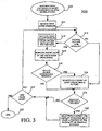
FIGURE 3 , aflowchart 300 represents an alternative to the trick mode discussed with respect toflowchart 200. As shown inflowchart 300, steps 310 - 314 are substantially similar to steps 210 - 214 offlowchart 200 and, accordingly, warrant no discussion here. The only difference is that if no pictures are to be repeated as determined atdecision block 313, then theflowchart 300 can continue atstep 324. Atstep 316, during the trick mode command, the bit rate of the trick mode video signal can be monitored. Monitoring the bit rate may be necessary during a trick mode because several pictures in the video signal may be repeated one or more times thereby resulting in an increased bit rate. In certain cases, this increased bit rate may exceed the maximum allowable bit rate for the transmission channel that is carrying the video signal. For purposes of the invention, this maximum allowable bit rate for the transmission channel can be referred to as a predetermined threshold. - At
decision block 318, it can be determined whether the bit rate of the trick mode video signal has exceeded this predetermined threshold. If the bit rate has not reached the predetermined threshold and the trick mode is to continue, then theflowchart 300 can continue atdecision block 326. Referring back to step 318, if the bit rate has exceeded the predetermined threshold, then dummy B pictures can be inserted in the trick mode video signal, as shown atstep 324. Also, the display indicators of at least a portion of the original pictures can be modified, as shown atsteps - The procedures shown in
steps flowchart 200. Thus, the insertion of dummy B pictures can occur based on the monitoring of the bit rate of the trick mode video signal and can be performed if this bit rate exceeds a predetermined threshold. Atstep 320, it can be determined whether the trick mode is to continue. If yes, then theflowchart 300 can resume atstep 313. If not, the process can end atstep 322. - Although the present invention has been described in conjunction with the embodiments disclosed herein, it should be understood that the foregoing description is intended to illustrate and not limit the scope of the invention as defined by the claims.
Claims (14)
- A method of performing a trick mode playback of a video signal, comprising:reading (210, 310) a video signal containing a plurality of progressively scanned original pictures wherein each of the progressively scanned original pictures contains a display indicator; receiving a trick mode command;characterised by the steps of:judging whether to repeat the insertion of at least one of the progressively scanned original pictures in the video signal; andif it is judged to repeat the insertion of at least one of the progressively scanned original pictures in the video signal,
inserting at least one of the progressively scanned original pictures in the video signal; and
modifying (220, 328) the display indicators of at least a portion of the plurality of the progressively scanned original pictures to reflect an intended display order;
transmitting the video signal with the inserted progressively scanned original pictures; monitoring the bit rate of the transmitted video signal; and
if the bit rate of the transmitted video signal exceeds a predetermined threshold:locating in the video signal one or more suitable progressively scanned original pictures;signalling that a suitable progressively scanned original picture has been located;generating dummy bidirectional predictive (B) pictures corresponding to the located one or more suitable progressively scanned original pictures;inserting at least one of said dummy bidirectional predictive (B) pictures in the video signal;modifying the display indicators of at least a portion of the plurality of the progressively scanned original pictures to reflect an intended display order;transmitting the video signal with at least one inserted dummy bidirectional predictive (B) picture for remote decoding; andif it is judged not to repeat the insertion of at least one of the progressively scanned original pictures in the video signal,
locating in the video signal one or more suitable progressively scanned original pictures;
signalling that a suitable progressively scanned original picture has been located;
generating a dummy bidirectional predictive (B) picture corresponding to the located one or more suitable progressively scanned original pictures;
inserting at least one of said dummy bidirectional predictive (B) pictures in the video signal;
transmitting the video signal with at least one inserted dummy bidirectional predictive picture (B) for remote decoding. - The method according to claim 1, wherein the display indicator is a temporal reference field.
- The method according to claim 2, wherein each temporal reference field has an integer value and the step of modifying the temporal reference field of at least a portion of the plurality of original pictures comprises the step of incrementally increasing by one the integer value of the temporal reference field each time an original picture is repeated and each time a dummy bidirectional predictive picture is inserted in the trick mode video signal.
- The method according to claim 1, wherein each dummy bidirectional predictive picture is predicted from a reference picture.
- The method according to claim 4, wherein the reference picture is an intra picture.
- The method according to claim 4, wherein the reference picture is a predictive picture.
- The method according to claim 1, wherein at least a portion of the trick mode video signal is decoded by a remote decoder.
- A system (100) including a controller (110) for reading data from and writing data to a storage medium (112), a searching engine (114) adapted to locating one or more particular types of pictures in a video signal representative stream read from the storage medium (112), a remote decoder (119A) for decoding received video data, a microprocessor (116) operable to control the operation of the controller and the searching engine for performing a trick mode playback of a video signal;
the controller (110) reads a video signal containing a plurality of progressively scanned original pictures wherein each of the progressively scanned original pictures contains a display indicator from the storage medium (112);
the microprocessor (116) receives a trick mode command;
characterised in that:if the microprocessor judges to repeat the insertion of at least one of the progressively scanned original pictures in the video signal,
the microprocessor inserts at least one of the progressively scanned original pictures in the video signal; and
modifies the display indicators of at least a portion of the plurality of the progressively scanned original pictures to reflect an intended display order; and
the microprocessor (116) transmits the video signal with the inserted progressively scanned original pictures to the remote decoder (119A) for decoding; and
monitors the bit rate of the transmitted video signal; and
if the bit rate of the transmitted video signal exceeds a predetermined threshold:the microprocessor (116) signals the searching engine (114) to locate in the video signal one or more suitable progressively scanned original pictures; andthe searching engine (114) signals the microprocessor (116) that a suitable progressively scanned original picture has been located;the microprocessor generates dummy bidirectional predictive (B) picture or pictures corresponding to the located one or more suitable progressively scanned original pictures; andthe microprocessor (116) inserts at least one of said dummy bidirectional predictive pictures in the video signal; andthe microprocessor (116) modifies the display indicators of at least a portion of the plurality of the progressively scanned original pictures to reflect an intended display order; andthe microprocessor (116) transmits the video signal with at least one inserted dummy bidirectional predictive (B) pictureto the remote decoder (119A) for decoding; andif the microprocessor judges not to repeat the insertion of at least one of the progressively scanned original pictures in the video signal,
the microprocessor (116) signals the searching engine (114) to locate in the video signal one or more suitable progressively scanned original pictures;
the searching engine (114) signals the microprocessor (116) that a suitable progressively scanned original picture has been located; the microprocessor generates a dummy bidirectional predictive (B) picture corresponding to the located one or more suitable progressively scanned original pictures;
the microprocessor (116) inserts at least one of said dummy bidirectional predictive (B) pictures in the video signal;
the microprocessor (116) transmits the video signal with at least one inserted dummy bidirectional predictive (B) picture to the remote decoder (119A) for decoding. - The system according to claim 8, wherein the display indicator is a temporal reference field.
- The system according to claim 9, wherein each temporal reference field has an integer value and the step of selectively modifying the temporal reference field of at least a portion of the plurality of original pictures comprises the step of incrementally increasing by one the integer value of the temporal reference field each time an original picture is repeated or when a dummy bidirectional predictive picture is inserted in the trick mode video signal.
- The system according to claim 8, wherein each dummy bidirectional predictive picture is predicted from a reference picture.
- The system according to claim 11, wherein the reference picture is an intra picture.
- The system according to claim 11, wherein the reference picture is a predictive picture.
- The system according to claim 8, further comprising a remote decoder (119A) for remotely decoding at least a portion of the trick mode video signal.
Applications Claiming Priority (3)
| Application Number | Priority Date | Filing Date | Title |
|---|---|---|---|
| US10/197,233 US7106945B2 (en) | 2002-07-16 | 2002-07-16 | Trick mode using dummy bidirectional predictive pictures |
| US197233 | 2002-07-16 | ||
| PCT/US2003/021372 WO2004008749A1 (en) | 2002-07-16 | 2003-07-09 | Trick mode using dummy bidirectional predictive pictures |
Publications (3)
| Publication Number | Publication Date |
|---|---|
| EP1540950A1 EP1540950A1 (en) | 2005-06-15 |
| EP1540950A4 EP1540950A4 (en) | 2009-05-06 |
| EP1540950B1 true EP1540950B1 (en) | 2011-05-18 |
Family
ID=30115124
Family Applications (1)
| Application Number | Title | Priority Date | Filing Date |
|---|---|---|---|
| EP03764390A Expired - Lifetime EP1540950B1 (en) | 2002-07-16 | 2003-07-09 | Trick mode using dummy bidirectional predictive pictures |
Country Status (10)
| Country | Link |
|---|---|
| US (1) | US7106945B2 (en) |
| EP (1) | EP1540950B1 (en) |
| JP (1) | JP4388474B2 (en) |
| KR (1) | KR100967312B1 (en) |
| CN (1) | CN100420292C (en) |
| AU (1) | AU2003247940A1 (en) |
| BR (2) | BR0312642A (en) |
| MX (1) | MXPA05000675A (en) |
| MY (1) | MY135047A (en) |
| WO (1) | WO2004008749A1 (en) |
Families Citing this family (1)
| Publication number | Priority date | Publication date | Assignee | Title |
|---|---|---|---|---|
| US20060098739A1 (en) * | 2004-11-09 | 2006-05-11 | Lsi Logic Corporation | Video frame encoder driven by repeat decisions |
Family Cites Families (9)
| Publication number | Priority date | Publication date | Assignee | Title |
|---|---|---|---|---|
| US5535008A (en) * | 1993-03-16 | 1996-07-09 | Victor Company Of Japan, Ltd. | Method for jump-reproducing video data of moving picture coded with high efficiency |
| US5867625A (en) * | 1994-10-20 | 1999-02-02 | Thomson Consumer Electronics, Inc. | Digital VCR with trick play steam derivation |
| JPH08140042A (en) * | 1994-11-07 | 1996-05-31 | Sony Corp | Image data reproducing apparatus and recording / reproducing apparatus |
| JP3484834B2 (en) * | 1995-07-28 | 2004-01-06 | ソニー株式会社 | Data encoding / decoding method and apparatus |
| US5956088A (en) | 1995-11-21 | 1999-09-21 | Imedia Corporation | Method and apparatus for modifying encoded digital video for improved channel utilization |
| US6445738B1 (en) * | 1996-04-25 | 2002-09-03 | Opentv, Inc. | System and method for creating trick play video streams from a compressed normal play video bitstream |
| US6219381B1 (en) * | 1997-05-26 | 2001-04-17 | Kabushiki Kaisha Toshiba | Image processing apparatus and method for realizing trick play |
| US6865747B1 (en) * | 1999-04-01 | 2005-03-08 | Digital Video Express, L.P. | High definition media storage structure and playback mechanism |
| JP4538908B2 (en) * | 2000-06-14 | 2010-09-08 | ソニー株式会社 | Data conversion apparatus and method |
-
2002
- 2002-07-16 US US10/197,233 patent/US7106945B2/en not_active Expired - Lifetime
-
2003
- 2003-07-09 WO PCT/US2003/021372 patent/WO2004008749A1/en not_active Ceased
- 2003-07-09 JP JP2004521569A patent/JP4388474B2/en not_active Expired - Fee Related
- 2003-07-09 AU AU2003247940A patent/AU2003247940A1/en not_active Abandoned
- 2003-07-09 BR BRPI0312642-0A patent/BR0312642A/en not_active IP Right Cessation
- 2003-07-09 KR KR1020057000786A patent/KR100967312B1/en not_active Expired - Fee Related
- 2003-07-09 CN CNB038170639A patent/CN100420292C/en not_active Expired - Fee Related
- 2003-07-09 BR BRPI0312642-0A patent/BRPI0312642B1/en unknown
- 2003-07-09 EP EP03764390A patent/EP1540950B1/en not_active Expired - Lifetime
- 2003-07-09 MX MXPA05000675A patent/MXPA05000675A/en active IP Right Grant
- 2003-07-15 MY MYPI20032630A patent/MY135047A/en unknown
Also Published As
| Publication number | Publication date |
|---|---|
| JP2005533436A (en) | 2005-11-04 |
| MY135047A (en) | 2008-01-31 |
| EP1540950A4 (en) | 2009-05-06 |
| AU2003247940A1 (en) | 2004-02-02 |
| BRPI0312642B1 (en) | 2018-06-05 |
| CN1669311A (en) | 2005-09-14 |
| MXPA05000675A (en) | 2005-03-31 |
| BR0312642A (en) | 2007-06-26 |
| WO2004008749A1 (en) | 2004-01-22 |
| KR100967312B1 (en) | 2010-07-07 |
| JP4388474B2 (en) | 2009-12-24 |
| EP1540950A1 (en) | 2005-06-15 |
| US20040013404A1 (en) | 2004-01-22 |
| KR20050028032A (en) | 2005-03-21 |
| US7106945B2 (en) | 2006-09-12 |
| CN100420292C (en) | 2008-09-17 |
Similar Documents
| Publication | Publication Date | Title |
|---|---|---|
| US20030159152A1 (en) | Fast motion trick mode using dummy bidirectional predictive pictures | |
| WO2003036971A1 (en) | Trick modes using non-progressive dummy bidirectional predictive pictures | |
| US7174086B2 (en) | Trick mode using dummy predictive pictures | |
| US7257312B2 (en) | Fast motion trick mode using dummy predictive pictures | |
| US6990287B2 (en) | Fast motion trick mode using dummy bidirectional predictive pictures | |
| US20030079228A1 (en) | Searching for frames to perform a trick mode | |
| EP1540950B1 (en) | Trick mode using dummy bidirectional predictive pictures | |
| US7756393B2 (en) | Frame advance and slide show trick modes | |
| EP1438848B1 (en) | Trick mode on bidirectional predictive frames |
Legal Events
| Date | Code | Title | Description |
|---|---|---|---|
| PUAI | Public reference made under article 153(3) epc to a published international application that has entered the european phase |
Free format text: ORIGINAL CODE: 0009012 |
|
| 17P | Request for examination filed |
Effective date: 20050204 |
|
| AK | Designated contracting states |
Kind code of ref document: A1 Designated state(s): AT BE BG CH CY CZ DE DK EE ES FI FR GB GR HU IE IT LI LU MC NL PT RO SE SI SK TR |
|
| AX | Request for extension of the european patent |
Extension state: AL LT LV MK |
|
| RAP1 | Party data changed (applicant data changed or rights of an application transferred) |
Owner name: THOMSON LICENSING |
|
| DAX | Request for extension of the european patent (deleted) | ||
| RBV | Designated contracting states (corrected) |
Designated state(s): DE FR GB IT |
|
| A4 | Supplementary search report drawn up and despatched |
Effective date: 20090403 |
|
| 17Q | First examination report despatched |
Effective date: 20091014 |
|
| RAP1 | Party data changed (applicant data changed or rights of an application transferred) |
Owner name: THOMSON LICENSING |
|
| GRAP | Despatch of communication of intention to grant a patent |
Free format text: ORIGINAL CODE: EPIDOSNIGR1 |
|
| GRAS | Grant fee paid |
Free format text: ORIGINAL CODE: EPIDOSNIGR3 |
|
| GRAA | (expected) grant |
Free format text: ORIGINAL CODE: 0009210 |
|
| AK | Designated contracting states |
Kind code of ref document: B1 Designated state(s): DE FR GB IT |
|
| REG | Reference to a national code |
Ref country code: GB Ref legal event code: FG4D |
|
| REG | Reference to a national code |
Ref country code: DE Ref legal event code: R096 Ref document number: 60337173 Country of ref document: DE Effective date: 20110630 |
|
| PLBE | No opposition filed within time limit |
Free format text: ORIGINAL CODE: 0009261 |
|
| STAA | Information on the status of an ep patent application or granted ep patent |
Free format text: STATUS: NO OPPOSITION FILED WITHIN TIME LIMIT |
|
| 26N | No opposition filed |
Effective date: 20120221 |
|
| REG | Reference to a national code |
Ref country code: DE Ref legal event code: R097 Ref document number: 60337173 Country of ref document: DE Effective date: 20120221 |
|
| REG | Reference to a national code |
Ref country code: FR Ref legal event code: PLFP Year of fee payment: 14 |
|
| REG | Reference to a national code |
Ref country code: FR Ref legal event code: PLFP Year of fee payment: 15 |
|
| REG | Reference to a national code |
Ref country code: DE Ref legal event code: R082 Ref document number: 60337173 Country of ref document: DE Representative=s name: DEHNS, DE Ref country code: DE Ref legal event code: R082 Ref document number: 60337173 Country of ref document: DE Representative=s name: HOFSTETTER, SCHURACK & PARTNER PATENT- UND REC, DE |
|
| REG | Reference to a national code |
Ref country code: FR Ref legal event code: PLFP Year of fee payment: 16 |
|
| REG | Reference to a national code |
Ref country code: DE Ref legal event code: R082 Ref document number: 60337173 Country of ref document: DE Representative=s name: DEHNS, DE Ref country code: DE Ref legal event code: R081 Ref document number: 60337173 Country of ref document: DE Owner name: INTERDIGITAL CE PATENT HOLDINGS SAS, FR Free format text: FORMER OWNER: THOMSON LICENSING, ISSY-LES-MOULINEAUX, FR |
|
| REG | Reference to a national code |
Ref country code: GB Ref legal event code: 732E Free format text: REGISTERED BETWEEN 20190926 AND 20191002 |
|
| PGFP | Annual fee paid to national office [announced via postgrant information from national office to epo] |
Ref country code: IT Payment date: 20190725 Year of fee payment: 17 Ref country code: FR Payment date: 20190725 Year of fee payment: 17 |
|
| PGFP | Annual fee paid to national office [announced via postgrant information from national office to epo] |
Ref country code: GB Payment date: 20190729 Year of fee payment: 17 |
|
| PGFP | Annual fee paid to national office [announced via postgrant information from national office to epo] |
Ref country code: DE Payment date: 20190930 Year of fee payment: 17 |
|
| REG | Reference to a national code |
Ref country code: DE Ref legal event code: R119 Ref document number: 60337173 Country of ref document: DE |
|
| GBPC | Gb: european patent ceased through non-payment of renewal fee |
Effective date: 20200709 |
|
| PG25 | Lapsed in a contracting state [announced via postgrant information from national office to epo] |
Ref country code: FR Free format text: LAPSE BECAUSE OF NON-PAYMENT OF DUE FEES Effective date: 20200731 Ref country code: GB Free format text: LAPSE BECAUSE OF NON-PAYMENT OF DUE FEES Effective date: 20200709 |
|
| PG25 | Lapsed in a contracting state [announced via postgrant information from national office to epo] |
Ref country code: DE Free format text: LAPSE BECAUSE OF NON-PAYMENT OF DUE FEES Effective date: 20210202 |
|
| PG25 | Lapsed in a contracting state [announced via postgrant information from national office to epo] |
Ref country code: IT Free format text: LAPSE BECAUSE OF NON-PAYMENT OF DUE FEES Effective date: 20200709 |