EP1540892B1 - Netzwerk und Verfahren zur Bereitstellung von Schicht-2 virtuellen privaten Netwerken auf Basis von vermittelten virtuellen Verbindungen - Google Patents
Netzwerk und Verfahren zur Bereitstellung von Schicht-2 virtuellen privaten Netwerken auf Basis von vermittelten virtuellen Verbindungen Download PDFInfo
- Publication number
- EP1540892B1 EP1540892B1 EP03747758A EP03747758A EP1540892B1 EP 1540892 B1 EP1540892 B1 EP 1540892B1 EP 03747758 A EP03747758 A EP 03747758A EP 03747758 A EP03747758 A EP 03747758A EP 1540892 B1 EP1540892 B1 EP 1540892B1
- Authority
- EP
- European Patent Office
- Prior art keywords
- elements
- subset
- network
- layer
- provider
- Prior art date
- Legal status (The legal status is an assumption and is not a legal conclusion. Google has not performed a legal analysis and makes no representation as to the accuracy of the status listed.)
- Expired - Lifetime
Links
- 238000000034 method Methods 0.000 title claims description 18
- 230000007246 mechanism Effects 0.000 claims description 32
- 230000011664 signaling Effects 0.000 claims description 17
- 238000013507 mapping Methods 0.000 claims description 11
- 230000007727 signaling mechanism Effects 0.000 claims description 10
- 101710104937 Non-specific acid phosphatase Proteins 0.000 claims 2
- 230000008901 benefit Effects 0.000 description 9
- 238000010586 diagram Methods 0.000 description 7
- 238000005516 engineering process Methods 0.000 description 3
- 230000006870 function Effects 0.000 description 3
- 238000012986 modification Methods 0.000 description 3
- 230000004048 modification Effects 0.000 description 3
- 230000003287 optical effect Effects 0.000 description 3
- 230000003116 impacting effect Effects 0.000 description 2
- 230000003068 static effect Effects 0.000 description 2
- ABEXEQSGABRUHS-UHFFFAOYSA-N 16-methylheptadecyl 16-methylheptadecanoate Chemical compound CC(C)CCCCCCCCCCCCCCCOC(=O)CCCCCCCCCCCCCCC(C)C ABEXEQSGABRUHS-UHFFFAOYSA-N 0.000 description 1
- DIDGPCDGNMIUNX-UUOKFMHZSA-N 2-amino-9-[(2r,3r,4s,5r)-5-(dihydroxyphosphinothioyloxymethyl)-3,4-dihydroxyoxolan-2-yl]-3h-purin-6-one Chemical compound C1=2NC(N)=NC(=O)C=2N=CN1[C@@H]1O[C@H](COP(O)(O)=S)[C@@H](O)[C@H]1O DIDGPCDGNMIUNX-UUOKFMHZSA-N 0.000 description 1
- 241000036569 Carp sprivivirus Species 0.000 description 1
- 241000764238 Isis Species 0.000 description 1
- 230000006978 adaptation Effects 0.000 description 1
- 238000004891 communication Methods 0.000 description 1
- 230000001419 dependent effect Effects 0.000 description 1
- 238000005417 image-selected in vivo spectroscopy Methods 0.000 description 1
- 238000012739 integrated shape imaging system Methods 0.000 description 1
- 238000002955 isolation Methods 0.000 description 1
- 230000007723 transport mechanism Effects 0.000 description 1
Images


Classifications
-
- H—ELECTRICITY
- H04—ELECTRIC COMMUNICATION TECHNIQUE
- H04L—TRANSMISSION OF DIGITAL INFORMATION, e.g. TELEGRAPHIC COMMUNICATION
- H04L12/00—Data switching networks
- H04L12/28—Data switching networks characterised by path configuration, e.g. LAN [Local Area Networks] or WAN [Wide Area Networks]
- H04L12/46—Interconnection of networks
- H04L12/4641—Virtual LANs, VLANs, e.g. virtual private networks [VPN]
- H04L12/4675—Dynamic sharing of VLAN information amongst network nodes
Definitions
- the present invention relates to a combination of switched Layer-2 Virtual Private Networks (VPNs) with a layer-3 VPN and is particularly concerned with flexible, on-demand switched MPLS/IP Layer-2 VPNs for Ethernet, ATM and Frame Relay SVCs while distributing customer routes through Layer-3 VPN mechanisms.
- VPNs Virtual Private Networks
- Ould-Brahim H et al. in an Internet draft article entitled "BGP/GMPLS Optical VPNs" (DRAFT-HENBRAHIM-BGPGMPLS-OVPN-01.TXT, published in July 2001), disclose a network and method for providing switched virtual circuit optical VPNs.
- a Virtual Private Network may be thought of as a private network constructed within a shared network infrastructure.
- these private networks are used by clients while the network infrastructure is supplied by providers.
- An object of the present invention is to provide an improved switched virtual circuit Layer-2 virtual private network arrangement combining Layer-3 VPNs technology with switched MPLS/IP L2VPNs for Ethernet, ATM and Frame Relay Circuits.
- a network for providing switched virtual circuit Layer-2 VPNs comprising: a set of elements interconnected by services; at least one first subset of said elements defining a private network (VPN A); at least one second subset of elements different from said first subset defining a provider network wherein at least two subgroups of said first subset of elements may be connected via said provider network; a provisioning mechanism used to define element membership In said first subset of elements; a plurality of customer ports maintained on said elements of said first subset of elements; a plurality of provider ports maintained on said second subset of elements, each of said plurality of provider ports connected by services to a customer port; a port information table at each element of said provider network having a provider port, said port information table containing mapping Information relating addresses of customer ports to addresses of provider ports; a signalling mechanism used to create Layer-2 connectivity between elements within said first subset of elements at the Layer-2 level across said second subset of elements; and a reachability distribution mechanism, used to
- Advantages of the present invention include real-time establishment of customer Layer-2 virtual circuits (VCs), and the ability to perform dynamic client reconfiguration via dynamic routing.
- Support for traffic engineering within the L2.5VPN service can be rendered without impacting traffic engineering on the provider network.
- L2.5VPN allows the ability to move one port of an L2.5VPN from one provider edge device (PE) to another and one provider to another without impacting the L2.5VPN and client network addressing.
- PE provider edge device
- a further advantage is that L2.5 dynamic bandwidth management supports Interworking to legacy Layer-2 VPNs.
- the invention further provides for the reachability distribution mechanism to use a Layer-3 VPN service.
- This Layer-3 VPN service could be one of piggybacking VPN routes onto the backbone Border Gateway Protocol, or alternatively that of using a virtual router redistribution scheme
- the Invention further provides for an auto-discovery mechanism for distributing said mapping Information to layer-2 port information tables of the provider network.
- This auto-discovery mechanism for distributing said mapping information uses Border Gateway Protocol in some instances.
- a method of organizing a network having a set of elements interconnected by services wherein at least one first subset of said elements defines a private network (VPN A) and at least one second subset of elements different from said first subset defines a provider network and wherein at least two subgroups of said first subset of elements may be connected via said provider network
- said method comprising: defining element membership in said first subset of elements via a provisioning mechanism; establishing a plurality of customer ports within said elements of said first subset of elements; establishing a plurality of provider ports within said second subset of elements, each of said plurality of provider ports connected by services to a customer port; establishing a port information table at each element of said provider network having a provider port, said port Information table containing mapping information relating addresses of customer ports to addresses of provider ports; receiving route information for said private network using a Layer 3 VPN service across said second subset of elements; establishing an Internet protocol-based control channel between a given element of said first sub
- FIG. 1 is a diagram of a generic network having a shared network infrastructure and Virtual Private Networks associated thereto;
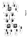
- FIG. 2 is a diagram of a network reference model including a plurality of customer edge devices, provider edge devices, and provider devices within the network;
- FIG. 3 is a diagram of the relation between Layer-2 datapath and network services provisioned by the service provider according to an embodiment of the invention
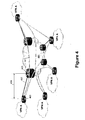
- FIG. 4 is a diagram of a L2.5VPN network according to an embodiment of the invention.
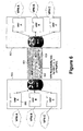
- FIG. 5 is a block diagram of SVC-L2.5VPN mechanisms according to an embodiment of the invention.
- FIG. 6 is a diagram of a L2.5VPN network depicting one version of Layer-3 reachability distribution according to an embodiment of the invention.
- FIG. 7 is a diagram of a L2.5VPN network depicting another version of Layer-3 reachability distribution according to an alternative embodiment of the invention.
- FIG. 1 there may be seen a generic network having a shared network infrastructure 100 with connected virtual private network sites 101.
- the VPN sites 101 make use of the network infrastructure 100 to interconnect physically remote sub-networks of particular VPNs.
- FIG. 2 there may be seen a network reference model showing a more detailed depiction of a network having a plurality of customer edge router/switches (CEs) 201, 202, 203, 204, 205, 206, 207, 208 and 209.
- the provider network has provider edge router/Layer-2 switches (PEs) 210, 212, and 214 as well as provider devices (P) 215, 216, 217, and 218 interior to the provider network.
- PEs provider edge router/Layer-2 switches
- P provider devices
- VPN A has a portion connected to CEs 201 and 202, and another portion connected to CE 206. Communication services between these remote portions of VPN A will be provided by the provider network. The same general situation obtains for VPN B, VPN C, and VPN D.
- the Switched Virtual Connection Layer-2.5 VPN (SVC-L2.5VPN) is a provider-based Layer-2 and Layer-3 VPN service that allows clients to request on-demand Layer-2 circuits while distributing customer routes through Layer-3 mechanisms.
- the SVC-L2.5VPN uses the mechanisms for SVC-L2VPN described in US Patent Application , hereby incorporated by reference, which are characterized by:
- Layer-2.5 VPN service combines both advantages of Layer-3 VPNs as described in RFC2547 and "switched" Layer-2 VPNs in that:
- the key objectives of Layer-2 use in L2.5VPNs includes:
- the client devices operate within the L2.5VPN space independently from the service provider network operations Subject to the defined constrained or restricted connectivity;
- Layer-2 switched model including such services as ATM, Frame Relay, Ethernet, Ethernet VLAN (PPP, HDLC, etc).
- the key objectives of Layer-3 use in L2.5VPNs includes:
- Layer-3 VPN constructs specifically distributing reachability using VPN distribution of VPN routes through the backbone BGP (as per RFC2547), or virtual router (VR) distribution of VPN routes;
- IP services for IP traffic if a L2.5VPN is provisioned to also provide a layer-3 VPN.
- a number of benefits for both client and provider are associated with SVC-L2.5VPNs as compared to legacy Layer-2 VPNs and SVC-L2VPNs.
- L2VPN addresses can be used for customer Layer-3 network
- the SVC-L2VPN circuit allowing the SVC-L2VPN circuit to be used as either a legacy Layer-2 circuit or as an MPLS LSP within the client network as needed;
- an L2.5VPN service can offer:
- L2.5VPN service with options to offer an Layer-3 VPN service (in addition to L2.5) on the same port if needed.
- Layer-2 VPN service (in addition to L2.5) consisting of:
- the Layer-3 advantages of a L2.5VPN service include:
- the PE devices manage customer routes for distribution only
- SP service provider
- the SP guarantees security and isolation of the VPNs between themselves and between the service provider's network(s) using a variety of options including that of legacy L2VPNs;
- the SP may offer per VPN basis extranet and internet access with an L2.5VPN.
- the SVC-L2.5VPN protocol requirements are as follows:
- MPLS signalling for example RSVP-TE with SVC-L2VPN extensions but not necessarily MPLS forwarding
- IP-based control channel for example, IP tunnelling
- the SVC-L2.5VPN Architecture Components may be summarized as follows:
- - Access is Layer-2 or Layer-3 VPNs
- Layer-2.5 VPN reachability distribution using a Layer-3 VPN service for distributing reachability, such as piggybacking VPN routes onto the backbone BGP as described in RFC2547, or by using a Virtual Router (VR) distribution scheme;
- a Layer-3 VPN service for distributing reachability, such as piggybacking VPN routes onto the backbone BGP as described in RFC2547, or by using a Virtual Router (VR) distribution scheme;
- VR Virtual Router
- Ports and links are logical constructs that uses (G)MPLS functions
- the SVC-L2.5VPN Building Blocks may be summarized as follows:
- L2PIT Layer-2 Port Information Table which maintains mapping between customer ports and provider ports (at the edges of the service provider network) provides local CEs with the information about other ports in the SVC-L2.5VPN, and is defined on a per SVC-L2.5VPN basis or for all the SVC-L23VPNs connected to PE;
- BGP-AD Layer-2 BGP based auto-discovery mechanism
- a reachability distribution mechanism which may be VPN distribution of VPN routes through the backbone BGP, or virtual router (VR) distribution of VPN routes.
- Customer site reachability may be determined either by:
- FIG. 3 there is depicted a representation of the relationship between a Customer Edge device 301 (CE), typically a router; the Layer-2 datapath 303; the private routes 305 defined separately from the datapath; the service provider network 307; and the provider provisioned Layer-2.5 VPN architecture layers 309.
- CE Customer Edge device
- Layer-2 datapath 303 the Layer-2 datapath 303
- private routes 305 defined separately from the datapath
- service provider network 307 the service provider network 307
- a L2.5VPN may be seen having a provider network with backbone 401, and provider edge device 403 (PE).
- PE provider edge device 403
- a customer edge device 405 (CE) connects via Layer-2/Layer-3 access 407 to the provider edge device 403.
- Between edge devices 403 and 405 run services 409 consisting of OSPF/RIP/BGP, and/or MPLS signalling for L2VPN.
- the Layer-2 Virtual circuit 411 connects remote sections of VPN A through the provider network.
- the reachability distribution is Layer-3 VPNs
- the datapath is Layer-2 VPNs.
- the CE 405 With L2.5VPNs with traffic engineering (L2.5VPN-TE), the CE 405 will form a forwarding adjacency out of that Switched Virtual Circuit (SVC) by advertising the SVC as a TE link into the same instance of ISIS/OSPF.
- SVC-L2VPN circuit can appear as an MPLS LSP to the CE 405 if the CE 405 is running MPLS.
- L2.5VPN provides for simplified provisioning in that:
- the customer could establish or terminate a Layer-2 connection between a pair of ports in its SVC-L2VPN without involving configuration or provisioning changes in any of the service provider equipment by using (G)MPLS signalling;
- the customer establishes a Layer-3 peering only with the attached PE.
- the SVC-L2.5VPN mechanisms are illustrated in FIG. 5 where the L2.5VPN 501 has two distinct operations: the Switched L2VPN operations 502, and the Layer-3 VPN operations 503.
- Subsumed under the Switched L2VPN operations 502 are the learning customer port information 504 and Port Information Table build out and Port Information distribution 506.
- Subsumed under the Layer-3 VPN operations 503 are the learning customer reachability information function 505 and the Layer-3 distribution phase function 507.
- Switched L2VPN Operations 502 can offer offline Traffic Engineering as an option. Switched L2VPN Operations 502 can also be accomplished by using GMPS based optical VPNs.
- Layer-3 VPN operations 503 are only for online Traffic Engineering, which is accomplished by Layer-3 VPNs mechanisms.
- FIG. 6 there is a depiction of a L2.5VPN with a reachability distribution scheme consisting of BGP updates through the backbone BGP.
- the backbone 601 connects a pair of Provider Edge devices 603, typically routers.
- a Virtual Router 605 connects to VPN A, while VPN Reachability Information 607 traverses backbone 601 via BGP updates 609. This is an illustration of the first of the Layer-3 reachability distribution methods.
- FIG. 7 illustrates a L2.5VPN with a Virtual Router reachability distribution.
- VPN A 701 connects to Provider Edge device 703, typically a router, which connects across the provider network to a second Provider Edge device 705.
- Virtual Routers 704 and 706 provide the virtual routing mechanism within the Provider Edge devices.
- Item 709 represents a routing instance, and items 711 show routing updates providing per VPN reachability information along tunnels 707 which run along the backbones 713 of the provider network. This is an illustration of the second of the alternate Layer-3 reachability distribution methods.
Landscapes
- Engineering & Computer Science (AREA)
- Computer Security & Cryptography (AREA)
- Computer Networks & Wireless Communication (AREA)
- Signal Processing (AREA)
- Data Exchanges In Wide-Area Networks (AREA)
- Telephonic Communication Services (AREA)
Claims (20)
- Netzwerk zur Bereitstellung von virtuellen Wählverbindungs-Schicht-2-VPNs, wobei das Netzwerk Folgendes umfasst:einen Satz von Elementen, die miteinander durch Dienste verbunden sind;wobei zumindest eine erste Teilmenge der Elemente ein privates Netzwerk (405, VPN A) definiert;
wobei zumindest eine zweite Teilmenge der Elemente, die von der ersten Teilmenge verschieden ist, ein Diensteanbieter-Netzwerk (401) definiert, wobei zumindest zwei Teilgruppen der ersten Teilmenge von Elementen über das Diensteanbieter-Netzwerk miteinander verbunden werden können;
ein Bereitstellungs-Mechanismus (309), der zur Definition einer Element-Mitgliedschaft in der ersten Teilmenge von Elementen verwendet wird;
eine Vielzahl von Kunden-Ports, die auf den Elementen der ersten Teilmenge von Elementen unterhalten werden;
eine Vielzahl von Diensteanbieter-Ports, die auf der zweiten Teilmenge von Elementen unterhalten werden, wobei jeder der Vielzahl von Diensteanbieter-Ports durch Dienste (407) mit einem Kunden-Port verbunden ist;
eine Pfad-Informations-Tabelle an jedem Element des Diensteanbieter-Netzwerkes, das einen Diensteanbieter-Port aufweist, wobei die Pfad-Informations-Tabelle Umsetzungs-Information enthält, die Adressen von Kunden-Ports zu Adressen von Diensteanbieter-Ports in Beziehung setzt;
einen Signalisierungs-Mechanismus (502), der zur Schaffung einer Schicht-2-Verbindungsmöglichkeit zwischen Elementen innerhalb der ersten Teilmenge von Elementen an der Schicht-2-Ebene über die zweite Teilmenge von Elementen hinweg verwendet wird; und
einen Erreichbarkeits-Verteilungs-Mechanismus (503), der zur Verteilung von Routen-Information für das private Netzwerk verwendet wird, wobei der Erreichbarkeits-Verteilungs-Mechanismus einen Schicht-3-VPN-Dienst verwendet; und
ein Internet-Protokoll basierter Steuerkanal zwischen einem vorgegebenen Element der ersten Teilmenge von Elementen und einem vorgegebenen Element der zweiten Teilmenge von Elementen. - Netzwerk zur Bereitstellung virtueller Wählverbindungs-Schicht-2-VPNs gemäß Anspruch 1, bei dem die Verwendung des Schicht-3-VPN-Dienstes die Verwendung eines Rand-Überleiteinrichtungs-Protokolls zur Verteilung der Routen-Information für das private Netzwerk beinhaltet.
- Netzwerk zur Bereitstellung von virtuellen Wählverbindungs-Schicht-2-VPNs nach Anspruch 1, bei dem die Verwendung des Schicht-3-VPN-Dienstes die Verwendung eines virtuellen Router-Neuverteilungs-Schemas zur Verteilung von Routen-Information für das private Netzwerk beinhaltet.
- Netzwerk zur Bereitstellung von virtuellen Wählverbindungs-Schicht-2-VPNs nach Anspruch 1, bei dem der Signalislerungs-Mechanismus (502) ein MPLS-Signalisierungs-Mechanismus ist.
- Netzwerk zur Bereitstellung von virtuellen Wählverbindungs-Schicht-2-VPNs nach Anspruch 1, das weiterhin einen Auto-Ermittlungs-Mechanismus zur Verteilung der Umsetzungs-Information an jedes genannte Element des Diensteanbieter-Netzwerkes umfasst.
- Netzwerk zur Bereitstellung von virtuellen Wählverbindungs-Schicht-2-VPNs nach Anspruch 5, bei dem der Auto-Ermittlungs-Mechanismus zur Verteilung der Umsetzungs-Information das Rand-Überleiteinrichtungs-Protokoll (BGP) verwendet.
- Netzwerk zur Bereitstellung von virtuellen Wählverbindungs-Schicht-2-VPNs nach Anspruch 1, bei dem der Bereitstellungs-Mechanismus (309) in Verbindung mit dem Signalisierungs-Mechanismus (502) betrieben wird, um die Element-Verbindungsmöglichkeit mit Elementen der ersten Teilmenge zu beschränken.
- Netzwerk zur Bereitstellung von virtuellen Wählverbindungs-Schicht-2-VPNs nach Anspruch 1, bei dem die Daten und Signalisierungsdienste IP-signalisierungsdienste haben.
- Netzwerk zur Bereitstellung von virtuellen Wählverbindungs-Schicht-2-VPNs nach Anspruch 1, bei dem die Kunden-Port-Adressen lediglich innerhalb der ersten Teilmenge von Elementen einzigartig sein müssen.
- Netzwerk zur Bereitstellung von virtuellen Wählverbindungs-Schicht-2-VPNs nach Anspruch 1, bei dem die Kunden-Port-Adressen und die Diensteanbieter-Port-Adressen ein Adresslerungs-Schema verwenden, das aus der Gruppe von IPv4, IPv6 und NSAP ausgewählt ist.
- Verfahren zur Organisation eines Netzwerkes mit einem Satz von Elementen, die durch Dienste miteinander verbunden sind, wobei zumindest eine erste Teilmenge der Elemente ein privates Netzwerk (405, VPN A) definiert, und zumindest eine zweite Teilmenge der Elemente, die von der ersten Teilmenge verschieden ist, ein Diensteanbieter-Netzwerk (401) definiert, und wobei zumindest zwei Teilgruppen der ersten Teilmenge von Elementen über das Diensteanbieter-Netzwerk miteinander verbunden werden können, wobei das Verfahren Folgendes umfasst:Definieren einer Element-Mitgliedschaft in der ersten Teilmenge von Elementen über einen Bereitstellungs-Mechanismus (309);Ausbilden einer Vielzahl von Kunden-Ports innerhalb von Elementen der ersten Teilmenge von Elementen;Ausbilden einer Vielzahl von Diensteanbieter-Ports innerhalb der zweiten Teilmenge von Elementen, wobei jeder der Vielzahl von Diensteanbieter-Ports durch Dienste (407) mit einem Kunden-Port verbunden ist;Ausbilden einer Port-Informations-Tabelle an jedem Element des Diensteanbieter-Netzwerkes, das einen Diensteanbieter-Port hat, wobei die Port-Informations-Tabelle Umsetzungs-Information enthält, die Adressen von Kunden-Ports zu Adressen von Dienstanbieter-Ports in Beziehung setzt;Empfangen von Routen-Information für das private Netzwerk unter Verwendung eines Schicht-3-VPN-Dienstes über die zweite Teilmenge von Elementen hinweg;Ausbilden eines Internet-Protokoll-basierten Steuerkanals zwischen einem vorgegebenen Element der ersten Teilmenge von Elementen und einem vorgegebenen Element der zweiten Teilmenge von Elementen; undSchaffen einer Schicht-2-Verbindungsmöglichkeit innerhalb der ersten Teilmenge von Elementen an der Schicht-2-Ebene über die zweite Teilmenge von Elementen hinweg über einen Signalisierungs-Mechanismus (502).
- Verfahren nach Anspruch 1, bei dem die Verwendung des Schicht-3-VPN-Dienstes die Verwendung des Rand-Überleiteinrichtung-Protokolls (BGP) zum Empfang von Routen-Information für das private Netzwerk beinhaltet.
- Verfahren nach Anspruch 12, bei dem die Verwendung des Schicht-3-VPN-Dienstes die Verwendung eines virtuellen Router-Neuverteilungs-Schemas zum Empfang von Routen-Information für das private Netzwerk beinhaltet.
- Verfahren nach Anspruch 11, das weiterhin den Schritt der Verteilung der Umsetzungs-Information an jedes Element des Diensteanbieter-Netzwerkes über einen Auto-Ermittlungs-Mechanismus umfasst.
- Verfahren nach Anspruch 14, bei dem der Auto-Ermittlungs-Mechanismus zur Verteilung der Umsetzungs-Information das Rand-Überleiteinrichtungs-Protokoll (BGP) verwendet.
- Verfahren nach Anspruch 11, das weiterhin den Schritt der Beschränkung der Element-Verbindungsfähigkeit mit Elementen der ersten Teilmenge über den Bereitstellungs-Mochanismus (309) umfasst, der in Verbindung mit dem Signalisierungs-Mechanismus (502) arbeitet.
- Verfahren nach Anspruch 11, bei dem der Signalisierungs-Mechanismus (502) ein MPLS-Signalisierungs-Mechanismus ist.
- Verfahren nach Anspruch 11, bei dem die Daten-und Signalisierungsdienste IP-Signalisierungsdienste haben.
- Verfahren nach Anspruch 11, bei dem die Kunden-Port-Adressen lediglich innerhalb der ersten Teilmenge von Elementen einzigartig sein müssen.
- Verfahren nach Anspruch 11, bei dem die Kunden-Port-Adressen und die Diensteanbieter-Port-Adressen ein Adressierungsschema verwenden, das aus der Gruppe von IPv4, lPv6 und NSAP ausgewählt ist.
Applications Claiming Priority (3)
| Application Number | Priority Date | Filing Date | Title |
|---|---|---|---|
| US40932502P | 2002-09-09 | 2002-09-09 | |
| US409325P | 2002-09-09 | ||
| PCT/CA2003/001380 WO2004023733A2 (en) | 2002-09-09 | 2003-09-09 | Combined layer-2 and layer-3 virtual private network |
Publications (2)
| Publication Number | Publication Date |
|---|---|
| EP1540892A2 EP1540892A2 (de) | 2005-06-15 |
| EP1540892B1 true EP1540892B1 (de) | 2007-12-19 |
Family
ID=31978743
Family Applications (1)
| Application Number | Title | Priority Date | Filing Date |
|---|---|---|---|
| EP03747758A Expired - Lifetime EP1540892B1 (de) | 2002-09-09 | 2003-09-09 | Netzwerk und Verfahren zur Bereitstellung von Schicht-2 virtuellen privaten Netwerken auf Basis von vermittelten virtuellen Verbindungen |
Country Status (5)
| Country | Link |
|---|---|
| US (1) | US7467215B2 (de) |
| EP (1) | EP1540892B1 (de) |
| AU (1) | AU2003266876A1 (de) |
| DE (1) | DE60318221T2 (de) |
| WO (1) | WO2004023733A2 (de) |
Families Citing this family (19)
| Publication number | Priority date | Publication date | Assignee | Title |
|---|---|---|---|---|
| CN1180582C (zh) * | 2001-06-21 | 2004-12-15 | 华为技术有限公司 | 多标签协议交换虚拟私有网配置管理系统及其划分方法 |
| WO2004023838A2 (en) * | 2002-09-09 | 2004-03-18 | Nortel Networks Limited | Svc-l2 vpns: flexible on-demand switched mpls/ip layer-2 vpns for ethernet svc, atm and frame relay |
| WO2004071033A1 (ja) * | 2003-02-03 | 2004-08-19 | Nippon Telegraph And Telephone Corporation | 光ネットワーク、光エッジルータ及びそのプログラム、カットスルー方法およびエッジルータ |
| US7447751B2 (en) | 2003-02-06 | 2008-11-04 | Hewlett-Packard Development Company, L.P. | Method for deploying a virtual private network |
| US7558877B1 (en) * | 2003-09-12 | 2009-07-07 | Nortel Networks Limited | Self-configuring method and apparatus for providing secure communication between members of a group |
| CN100359876C (zh) * | 2004-06-25 | 2008-01-02 | 信息产业部电信研究院 | Ip电信网系统中实现虚拟专网的方法 |
| US7318108B2 (en) * | 2004-12-22 | 2008-01-08 | Cisco Technology, Inc. | Method and apparatus providing prioritized convergence in border gateway protocol |
| US7797382B2 (en) * | 2005-12-02 | 2010-09-14 | Alcatel Lucent | Virtual private network publish-subscribe multicast service |
| CN1992670B (zh) * | 2005-12-30 | 2010-08-11 | 华为技术有限公司 | 一种以太网承载帧中继的方法 |
| US7688819B2 (en) * | 2006-03-06 | 2010-03-30 | Cisco Technology, Inc. | Faster routing protocol convergence using efficient message markup |
| US8724505B2 (en) * | 2006-09-01 | 2014-05-13 | Ciena Corporation | Flexible mechanism for supporting virtual private network services based on source-independent distributed advertisements |
| CN101110745A (zh) * | 2007-08-14 | 2008-01-23 | 华为技术有限公司 | 衔接二层网络和三层网络的方法、装置和系统 |
| US7908353B2 (en) * | 2008-04-11 | 2011-03-15 | International Business Machines Corporation | Managing overlapping address spaces |
| US8098663B2 (en) * | 2008-07-08 | 2012-01-17 | Cisco Technology, Inc. | Carrier's carrier without customer-edge-to-customer-edge border gateway protocol |
| CN102137173B (zh) | 2010-12-27 | 2014-09-03 | 华为技术有限公司 | 路由信息发布方法、设备及虚拟专用网系统 |
| CN103368764B (zh) * | 2012-04-10 | 2018-05-04 | 中兴通讯股份有限公司 | 一种虚拟网络的实现方法及网络管理系统 |
| US9143408B2 (en) | 2012-07-30 | 2015-09-22 | Hewlett-Packard Development Company, L.P. | Interprovider virtual private network path identification |
| CN103957160B (zh) * | 2014-05-12 | 2017-04-19 | 华为技术有限公司 | 一种发送报文的方法及设备 |
| US20180309594A1 (en) * | 2017-04-20 | 2018-10-25 | At&T Intellectual Property I, L.P. | Systems and Methods for Creating an Integrated Layer 2-Layer 3 Hybrid VPN Network |
Family Cites Families (12)
| Publication number | Priority date | Publication date | Assignee | Title |
|---|---|---|---|---|
| US7315554B2 (en) * | 2000-08-31 | 2008-01-01 | Verizon Communications Inc. | Simple peering in a transport network employing novel edge devices |
| US6912592B2 (en) * | 2001-01-05 | 2005-06-28 | Extreme Networks, Inc. | Method and system of aggregate multiple VLANs in a metropolitan area network |
| US7155518B2 (en) * | 2001-01-08 | 2006-12-26 | Interactive People Unplugged Ab | Extranet workgroup formation across multiple mobile virtual private networks |
| US7136374B1 (en) * | 2001-03-19 | 2006-11-14 | Juniper Networks, Inc. | Transport networks supporting virtual private networks, and configuring such networks |
| US20030200339A1 (en) * | 2001-07-02 | 2003-10-23 | Globespanvirata Incorporated | Communications system using rings architecture |
| US20030026271A1 (en) * | 2001-07-03 | 2003-02-06 | Erb Guy C. | L2/L3 network with LSP-enabled virtual routing |
| US7099944B1 (en) * | 2001-07-13 | 2006-08-29 | Bellsouth Intellectual Property Corporation | System and method for providing network and service access independent of an internet service provider |
| US7127523B2 (en) * | 2001-07-27 | 2006-10-24 | Corrigent Systems Ltd. | Spanning tree protocol traffic in a transparent LAN |
| JP3868815B2 (ja) * | 2002-01-10 | 2007-01-17 | 富士通株式会社 | 通信システム |
| CA2369201A1 (en) * | 2002-01-24 | 2003-07-24 | Alcatel Canada Inc. | System and method for providing maintenance of fabric links for a network element |
| KR100496984B1 (ko) * | 2002-08-21 | 2005-06-23 | 한국전자통신연구원 | 레이블 분배 프로토콜의 확장을 이용한 QoS지원 2계층가상 사설 망 양방향 터널 설정 및 구성정보 분배방법 |
| US7664123B2 (en) * | 2004-01-22 | 2010-02-16 | Nortel Networks Limited | Generalized virtual router |
-
2003
- 2003-09-09 WO PCT/CA2003/001380 patent/WO2004023733A2/en not_active Ceased
- 2003-09-09 DE DE60318221T patent/DE60318221T2/de not_active Expired - Lifetime
- 2003-09-09 EP EP03747758A patent/EP1540892B1/de not_active Expired - Lifetime
- 2003-09-09 AU AU2003266876A patent/AU2003266876A1/en not_active Abandoned
- 2003-09-09 US US10/657,939 patent/US7467215B2/en not_active Expired - Fee Related
Non-Patent Citations (1)
| Title |
|---|
| None * |
Also Published As
| Publication number | Publication date |
|---|---|
| WO2004023733A2 (en) | 2004-03-18 |
| AU2003266876A1 (en) | 2004-03-29 |
| US20040049597A1 (en) | 2004-03-11 |
| AU2003266876A8 (en) | 2004-03-29 |
| US7467215B2 (en) | 2008-12-16 |
| WO2004023733A3 (en) | 2004-04-29 |
| EP1540892A2 (de) | 2005-06-15 |
| DE60318221D1 (de) | 2008-01-31 |
| DE60318221T2 (de) | 2008-04-10 |
Similar Documents
| Publication | Publication Date | Title |
|---|---|---|
| EP1540892B1 (de) | Netzwerk und Verfahren zur Bereitstellung von Schicht-2 virtuellen privaten Netwerken auf Basis von vermittelten virtuellen Verbindungen | |
| US7532630B2 (en) | Generalized layer-2 VPNs | |
| US6789121B2 (en) | Method of providing a virtual private network service through a shared network, and provider edge device for such network | |
| EP1713197B1 (de) | Verfahren zum implementieren der virtuell geleasten leitung | |
| US6493349B1 (en) | Extended internet protocol virtual private network architectures | |
| US20040165600A1 (en) | Customer site bridged emulated LAN services via provider provisioned connections | |
| US20060182122A1 (en) | Inter-autonomous-system virtual private network with autodiscovery and connection signaling | |
| US20050190757A1 (en) | Interworking between Ethernet and non-Ethernet customer sites for VPLS | |
| Zhang et al. | An overview of virtual private network (VPN): IP VPN and optical VPN | |
| US7280534B2 (en) | Managed IP routing services for L2 overlay IP virtual private network (VPN) services | |
| US20150146573A1 (en) | Apparatus and method for layer-2 and layer-3 vpn discovery | |
| EP1540893B1 (de) | Netzwerk und Verfahren zur Bereitstellung von Schicht-2 virtuellen privaten Netwerken auf Basis von vermittelten virtuellen Verbindungen | |
| EP1702438B1 (de) | Vorrichtung und verfahren zum verteilen von schicht-2-vpn-informationen | |
| WO2003105521A2 (en) | Technique for implementing a virtual private optical switched transport network using virtual private optical/tdm cross-connect technology | |
| Badran | Service provider networking infrastructures with MPLS | |
| Joseph et al. | Network convergence: Ethernet applications and next generation packet transport architectures | |
| Tatipamula et al. | Implementation of IPv6 services over a GMPLS-based IP/optical network | |
| CN114205187A (zh) | 一种适用于OptionC跨域的MPLS-VPN的端到端路径计算方法及装置 | |
| Halimi et al. | Overview on mpls virtual private networks | |
| Rathore et al. | Site-to-site vpn technologies: A survey | |
| Sharma et al. | On the issues in implementing the peer model in integrated optical networks | |
| Nakagawa et al. | Direction of next generation internet exchanges | |
| Gleeson et al. | A Framework for Provider Provisioned Virtual Private Networks< draft-ietf-ppvpn-framework-01. txt | |
| Tatipamula et al. | Design Implementation of IPv6 services over GMPLS based IP/Optical Network |
Legal Events
| Date | Code | Title | Description |
|---|---|---|---|
| PUAI | Public reference made under article 153(3) epc to a published international application that has entered the european phase |
Free format text: ORIGINAL CODE: 0009012 |
|
| 17P | Request for examination filed |
Effective date: 20050411 |
|
| AK | Designated contracting states |
Kind code of ref document: A2 Designated state(s): AT BE BG CH CY CZ DE DK EE ES FI FR GB GR HU IE IT LI LU MC NL PT RO SE SI SK TR |
|
| AX | Request for extension of the european patent |
Extension state: AL LT LV MK |
|
| DAX | Request for extension of the european patent (deleted) | ||
| RBV | Designated contracting states (corrected) |
Designated state(s): DE FR GB |
|
| RTI1 | Title (correction) |
Free format text: NETWORK AND METHOD FOR PROVIDING SWITCHED VIRTUAL CIRCUIT LAYER-2 VIRTUAL PRIVATE NETWORKS |
|
| GRAP | Despatch of communication of intention to grant a patent |
Free format text: ORIGINAL CODE: EPIDOSNIGR1 |
|
| GRAS | Grant fee paid |
Free format text: ORIGINAL CODE: EPIDOSNIGR3 |
|
| GRAA | (expected) grant |
Free format text: ORIGINAL CODE: 0009210 |
|
| AK | Designated contracting states |
Kind code of ref document: B1 Designated state(s): DE FR GB |
|
| REG | Reference to a national code |
Ref country code: GB Ref legal event code: FG4D |
|
| REF | Corresponds to: |
Ref document number: 60318221 Country of ref document: DE Date of ref document: 20080131 Kind code of ref document: P |
|
| ET | Fr: translation filed | ||
| PLBE | No opposition filed within time limit |
Free format text: ORIGINAL CODE: 0009261 |
|
| STAA | Information on the status of an ep patent application or granted ep patent |
Free format text: STATUS: NO OPPOSITION FILED WITHIN TIME LIMIT |
|
| 26N | No opposition filed |
Effective date: 20080922 |
|
| PGFP | Annual fee paid to national office [announced via postgrant information from national office to epo] |
Ref country code: GB Payment date: 20140826 Year of fee payment: 12 Ref country code: FR Payment date: 20140825 Year of fee payment: 12 |
|
| PGFP | Annual fee paid to national office [announced via postgrant information from national office to epo] |
Ref country code: DE Payment date: 20140930 Year of fee payment: 12 |
|
| REG | Reference to a national code |
Ref country code: DE Ref legal event code: R119 Ref document number: 60318221 Country of ref document: DE |
|
| GBPC | Gb: european patent ceased through non-payment of renewal fee |
Effective date: 20150909 |
|
| REG | Reference to a national code |
Ref country code: FR Ref legal event code: ST Effective date: 20160531 |
|
| PG25 | Lapsed in a contracting state [announced via postgrant information from national office to epo] |
Ref country code: GB Free format text: LAPSE BECAUSE OF NON-PAYMENT OF DUE FEES Effective date: 20150909 Ref country code: DE Free format text: LAPSE BECAUSE OF NON-PAYMENT OF DUE FEES Effective date: 20160401 |
|
| PG25 | Lapsed in a contracting state [announced via postgrant information from national office to epo] |
Ref country code: FR Free format text: LAPSE BECAUSE OF NON-PAYMENT OF DUE FEES Effective date: 20150930 |